1
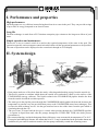
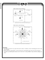
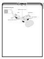
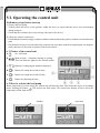
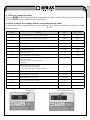
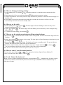
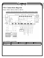
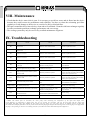
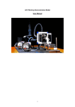
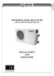
EN
SWIMMING POOL HEAT PUMP
(THP 55, THP 100, THP 120, THP 170)
INSTALLATION
AND
USER GUIDE
i
Read the instructions
EN
Contents
I.
II.
III.
IV.
V.
VI.
VII.
VIII.
IX.
Performance and properties ................................... 4
System design ........................................................ 4
Performance ........................................................... 5
Dimensions ............................................................ 6
Preparations for installation ................................... 6
Operating the control unit ...................................... 9
Connection diagram ............................................. 12
Maintenance ......................................................... 13
Troubleshooting ................................................... 13
Thank you for choosing our product and for your trust in our company. To ensure that you can fully enjoy
the product, please read these instructions carefully and strictly follow the user guide so as not to damage
the device and to avoid unnecessary injuries.
2
EN
I. Performance and properties
High performance
Our heat pumps are very efficient in transferring heat from air to water in the pool. They can provide savings
of up to 80% in energy compared to an electric heater.
Long life
The heat exchanger is made from a PVC/titanium composite pipe resistant to the long-term effects of pool
water.
Simple operation and maintenance
The device is easy to control: switch it on and set the required temperature of the water in the pool. The
system incorporates a microcomputer control unit which allows all the operational parameters to be specified.
The state of operation can be displayed on the control unit through an LCD display.
II. System design
colder air depleted
of energy
compressor
evaporator
pump
air flow
air flow
swimming pool cleaner
hot air
compressor
heat exchanger
swimming pool
ventilator
condenser
water heat exchanger
capillary tube
evaporator
(energy collector)
water outflow
water inlet
• Heat pumps make use of free heat from the sun by collecting and absorbing energy from the outside air.
• This device contains a ventilator which draws the outside air in and makes it flow over the surface of the
EVAPORATOR (energy collector). The liquid coolant in the EVAPORATOR pipeline absorbs the heat
from the outside air and the coolant vaporises.
• The warm gas in the pipeline passes through the COMPRESSOR which gathers the heat and increases the
temperature to generate very hot gas which then passes to the CONDENSER (water heat exchanger). This
is where the heat exchange occurs - the hot gas transfers heat to the colder water from the pool which is
circulating through the coil.
• The pool water is heated and the hot gas is cooled when passing through the CONDENSER pipeline
– it regains its liquid form and, after the passage through the CAPILLARY TUBE, the whole process
recommences.
• The current technology used in the heat pump allows efficient use even at an outside air temperature of 7 to 10 ºC.
For tropical and subtropical climates, this means that 26 to 32 ºC may be maintained in the pool under almost any
conditions all year round. In northern countries, the heat pump considerably extends the swimming season.
3
EN
III. Performance properties
Performance properties of a monoblock-type heat pump for swimming pools
Code
THP 55
THP 100
THP 120
THP 170
W
5500
9900
11800
17300
BTU
19000
34000
41300
59500
Heat input
W
1240
1940
2650
3670
Operating current for heating
A
5,5
9,6
13,3
18
1
1
Nominal heat output
Current supply
V/phase/Hz
220-240/1/50
Number of compressors
1
1
Scroll
Compressor
Number of ventilators
1
1
1
1
W
25
50
50
50
Ventilator speed
RPM
950
950
950
950
Noise
dB(A)
53
55
57
59
Mains pipe
mm
50
50
50
50
Water flow
m3/h
2-4
4-6
6-8
8-10
Decrease in water pressure
kpa
20
20
20
20
Coolant (R407C)
kg
0,8
1,3
1,3
2,1
935
1090
1090
1165
360
370
370
470
H
550
615
615
685
L
1060
1140
1140
1195
380
400
400
485
600
660
660
730
40
62
65
99
48
71
77
104
Input of ventilators
L
Net dimensions
Packaged dimensions
W
W
mm
mm
H
Weight
net
gross
kg
4
EN
IV. Dimensions
Dimensions of heat pumps (monoblock-type) for swimming pools
Model
THP 55
THP 100
THP 120
L
1000
1090
1090
W
360
370
370
H
550
612
612
E
81
84
84
F
200
270
270
Dimension
Unit: mm
Model
THP 170
Dimension
L
1165
W
470
H
685
A
440
B
760
F
325
G
81,5
Unit: mm
V. Preparations for installation
5.1 Selection of the installation position
• The heat pump has to be installed in a spacious and well ventilated place.
• Its position has to guarantee adequate free space for the exhaust (the location of the air inlet is shown
in the diagram on the next page).
• The heat pump has to be situated close to a drain or vent so as to make water discharge easier.
• The installation base or brace has to be firm enough to ensure smooth operation of the device.
• Make sure the device, when installed, is situated vertically, without any inclination.
• Do not install the device in places where there is contamination, corrosive gas or where dirt or fallen
leaves accumulate.
• The heat pump must not be installed in the vicinity of an inflammable or explosive environment or
near things that are a common cause of fire.
• Maintain the distances from obstacles as indicated with arrows in the picture below.
5
EN
Model with horizontal discharge
min. 1000 mm
air
inlet
air
inlet
min. 1000 mm from above
min.
1000 mm
min.
1000 mm
air
outlet
min. 2000 mm
Requirements for free space around the horizontal heat pump
Model with vertical discharge
more than 1000 mm
air
inlet
min. 1000 mm from above
min.
1000 mm
min.
1000 mm
air
inlet
air
inlet
air outlet
min. 2000 mm from above
Requirements for free space around the vertical heat pump
Warning:
• Do not put your hand or any object into the air outlet or ventilator, as this could damage the device and
cause an injury.
• In the event of any abnormalities, switch off the device immediately and contact an expert technician.
• If needed, you should place barriers next to the device to keep children away from the running heat
pump.
6
EN
5.2 Installation diagram
back pressure valve
filter
chlorinator
water pump
trap
back pressure valve
7
EN
VI. Operating the control unit
Preliminary steps before start-up
A) Inspect the heat pump
• Visually check the device or the pipeline within the device to ensure that the device was not damaged
during transport.
• Check that the ventilator does not touch any other part of the device.
B) Check the electric connections
• Check that the electricity supply complies with the technical data in this guide or on the device identification
plate.
• Check that the wiring is correctly and safely connected in accordance with the wiring diagram. An adequate
earth connection is necessary to protect from electric shocks.
6. 1 Picture of the control unit
A.
On / off button.
B.
Mode selector – automatic, heating or cooling.
There are indicator lights for the selected modes.
C.
or
Buttons for changing the numbers displayed.
D.
Button for setting the switch-on time.
E.
Button for setting the switch-off time.
F.
Button for adjusting the time.
6. 2 How to activate the heat pump
When connected to a power supply, the control unit will show the time. This means the device is in standby
mode. Pushing the button
will activate the heat pump. The control unit display will now show the
temperature of the input water.
Standby
Operation
8
EN
6. 3 How to change the mode
Press the
button to change the mode to automatic, heating or cooling. The appropriate indicator light
will be illuminated on the right side of the control unit.
6.4 How to check the settings and the current measured values
In the standby mode or operation mode, use the buttons
measured values
Parameter
or
to find the parameter 0-A and the current
Meaning
Range
Factory setting
0
Setting the return water temperature (cooling mode)
8-28ºC
12ºC
1
Setting the return water temperature (heating mode)
15-40ºC
40ºC
2
Defrosting cycle
30-90 min
45 min
3
Setting the pipeline temperature for the start of defrosting
0- –30ºC
-7ºC
4
Setting the pipeline temperature for the end of defrosting
2-30ºC
13ºC
5
Maximum defrosting time
1-12 min
8 min
6
Number of systems
1-2
1
7
Restart after electricity supply failure
0-1
1 (yes)
8
Type: only cooling 0/
heating and cooling 1/
heating and cooling + additional heating 2/
heating only 3
0-3
1
9
Different water pump operating mode
0 water pump works uninterruptedly
1 water pump works together with the heat pump
0-1
0
A
Setting the return water temperature (automatic mode)
8–60ºC
28ºC
B
Actual temperature of input water
-9 +90ºC
C
Actual temperature of output water
-9 +90ºC
D
Pipeline water temperature in system 1
-9 +90ºC
E
Pipeline water temperature in system 1 (only for a double system)
-9 +90ºC
F
Surrounding temperature
-9 +90ºC
Parameter 1
Current measured value
9
EN
6. 5 How to change parameter settings
1. In the standby mode, use buttons or to find the parameter 0-A and the current measured values
for B-F.
2. Simultaneously, for five seconds, press buttons and to activate parameter setting.
3. Change the parameter value until you hear a beep and until the parameter is indicated on the display as a
flashing value.
4. If no button is pressed on the control unit within five seconds, the electronics will save the data
automatically and will return to the standby mode.
6. 6 How to set the clock
1. In the standby mode, press button
. The hour digits will start flashing to show that they can be
changed using buttons or .
2. Again, press button
. The minute digits will start flashing to show that they can be changed using
or
buttons
.
3. To confirm the time setting, press button
.
6. 7 How to set the switch-on and switch-off time using the timer
a) Press button
to activate the timer switch-on time setting mode. The hour and minute digits will start
flashing.
b) Again, press button
to activate clock setting. The hour digits will start flashing to show that they can
be changed using buttons and .
c) Press button
to confirm the setting. The display will return to standby mode. The green indicator
light for the switch-on time of the timer will be illuminated.
d) To set the switch-off time of the timer, take the same steps. Instead of button
use button
.
The green indicator light for the switch-off time of the timer will be illuminated.
Note: You can set both the switch-on and switch-off times of the timer, or only one.
6. 8 How to cancel / reset the timer function
For activation, press button
or
. The appropriate indicator light will start flashing. To
cancel / reset the timer function, press button
.
6. 9 Lock / Unlock the keyboard
When you have finished setting the parameters, pressing buttons and simultaneously for three seconds
(until a beep is heard) will lock the keyboard. To unlock it, press these two buttons simultaneously for
other three seconds.
10
EN
VII. Connection diagram
Models: THP 55, THP 100, THP 120, THP 170
CONNECTION DIAGRAM FOR A SWIMMING POOL HEAT PUMP
four-way valve
ventilator pump
electric heating unit
blue
green / yellow
red
four-way valve
common
black
on
blue
sensor 1
sensor 2
sensor 3
1 exhaust temperature regulator
2 high-pressure sensor
low-pressure sensor
water pressure sensor
earth
common
blue
blue
green / yellow
black
blue
to electricity supply
surrounding pressure
green /
yellow
temperature of coil
blue
temperature of output water
red
blue
temperature of input water
red
control unit
connected by
cable
to water pump
electricity supply
Power conductor cross-sections
Code
THP 55
THP 100
THP 120
Cross-section
1,5 mm2
11
THP 170
EN
VIII. Maintenance
• Check that the device water inlet is open. It is necessary to avoid low water and air flows into the device
because they could worsen its performance and reliability. You have to clean the swimming pool filter
regularly to avoid damage to the device as a result of a dirty or blocked filter.
• The space around the device has to be dry, clean and well ventilated. Clean the side heat exchanger regularly
in order to maintain good heat exchange performance and save energy.
• The cooling system may only be serviced by certified maintenance engineers.
IX. Troubleshooting
CONTROL UNIT
FAULT
CAUSE
SOLUTION
PP 1
Input water temperature
Sensor fault
Broken or short-circuited sensor
Check or replace the sensor
PP 2
Output water temperature
Sensor fault
Broken or short-circuited sensor
Check or replace the sensor
PP 3
Fault in coil sensor 1
Broken or short-circuited sensor
Check or replace the sensor
PP 4
Fault in coil sensor 2
Broken or short-circuited sensor
Check or replace the sensor
PP 5
Fault in surrounding temperature sensor
Broken or short-circuited sensor
Check or replace the sensor
PP 6
The temperature of input and output water
is too high
Insufficient water output or too small
difference in water pressure
Check water output. Check that ventilation
is not blocked.
PP 7
Protection against freezing for cooling
Insufficient water output
Check water output. Check that ventilation
is not blocked.
EE 1
High pressure protection fault or system 1
protection fault
Defective protection of system 1
Check each place of system 1 protection,
remove the defect as stated in the fault table
on the system protection card
EE 2
High pressure protection fault or system 2
protection fault
Defective protection of system 2
Check each place of system 2 protection,
remove the defect as stated in the fault table
on the system protection card
EE 3
Fault in the water pressure sensor
Water circuit without water or with too little
water
Check water output. Make sure
the installation is not blocked.
Poor-quality or missing phase
(for a three-phase device)
Poor-quality or missing phase
Check power cable wiring.
EE 5*
PP6 fault occurs three times in 30 minutes
Insufficient water output or too small
difference in water pressure
Check water output. Check that installation
is not blocked.
EE 8
Fault in communication between the control
unit and electronics
Fault in connection between the control unit
connected with a cable and electronics
Check wiring.
Display empty
Display empty
Defrosting underway
* Notes: One minute after its activation, the water pump starts measuring the temperature of the input and output water.
If the difference in temperatures is higher than 13ºC for 10 seconds, the electronics will stop the heat pump and the control unit
will display fault PP6; after three minutes the heat pump will start again. If it stops three times in 30 minutes because of fault PP6,
the control unit will display fault EE5. It will be possible to start the heat pump again only after disconnecting and re-connecting the power supply. When
the pump is not operating or the device is in heating mode, the system does not monitor abnormal temperature differences.
12
EN
WARNING
• Before installation, check that the electricity supply complies with the technical conditions of your heat
pump. The details are specified on the plaque fitted to the device or in this guide.
• Install recommended electric protective devices in accordance with local regulations.
• The heat pump has to be earthed to protect you from electric shocks due to possible short circuits.
• This guide includes a wiring diagram.
• For safety reasons, do not make any unauthorised changes to the heat pump or carry out repairs to the
device without authorisation.
• Do not insert any objects into the pump when it is operating as they might touch the ventilator and
damage it or cause accidents (especially in the presence of children).
• Do not use the heat pump without a grille or protective plate as this could result in accidents or abnormal
operation of the device.
• If water gets into the device, immediately contact the supplier. The device may be used again only after
examination by our technicians.
• Unauthorized technicians may not adjust the sensors, valves or control units of the device.
Conditions of guarantee
The conditions of guarantee are governed by your supplier’s general conditions of trade and conditions of
guarantee.
Safe disposal of the product after its service life
After its service life is over, have the product disposed of ecologically by a specialized company.
Warranty claims and servicing
Warranty claims are governed by applicable consumer protection legislation. In the event a fault cannot be
rectified, please contact your supplier in writing.
Date................................................................
Supplier
13