1
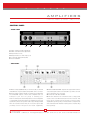
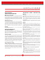
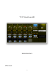
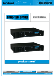
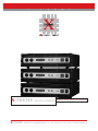
X
-
T
R
E
X-TREME Amplifiers
X-TREME
M
E
Stereo DSP Power Amplifiers
via Monti Urali, 31 - 42029 Reggio Emilia (Italy) • ph. +39 - 0522 - 557735 • fax +39 - 0522 - 393733 • e-mail: [email protected]
X
-
T
R
E
M
E
amplifiers
s t e r e o
D S P
p o w e r
a m p l i f i e r
FEATURE
• Integrated system;
• Electronic protections: short circuit/overload protection, overheating protection and direct current excursion protection;
• Network control;
• Power supply: RMS 2 x 1700W (4Ω) RMS 2 x 1000W (8Ω) XT3400
RMS 2 x 1300W (4Ω), RMS 2 x 850W (8Ω) XT2600
RMS 2 x 1000W (4Ω), RMS 2 x 650W (8Ω) XT2000
• Built-in 48-bit DSP processor and dynamic range up to 116dB, 48kHz sampling rate A/D, D/A;
• Low noise and lower distortion;
• Well-designed signal generator: sin wave and white noise;
• S/PDIF input/output (option);
• Matrix control, up to 255 units controlled by selecting address code;
• Save and recall all parameters via PC parallel port 3 band PEQ, limiter (threshold, attack time and release time adjusted),
delay (max 8ms), phase invert, input gain control;
• Two crossover: range, 20Hz-20kHz.
Crossover frequency adjusted. Slope: -6, - 12, -18, -24 and -48 dB butterworth or Linkwitz-Riley;
• 20 user memories available;
• THD+N: 0.08%@1kHz;
• Frequency response: 20Hz-20kHz;
• 2 x 20 LCD display with backlit.
2
X-TREME
via Monti Urali, 31 - 42029 Reggio Emilia (Italy) • ph. +39 - 0522 - 557735 • fax +39 - 0522 - 393733 • e-mail: [email protected]
X
-
T
R
E
M
E
amplifiers
s t e r e o
D S P
p o w e r
a m p l i f i e r
CONTROL PANEL
• FRONT PANEL
1
2
5
3
4
6
1. CHA: channel A volume adjustment;
2. CHB: channel B volume adjustment;
3. Input interface to PC;
4. Output interface to other unit pc port;
5. 2 x 20 LCD display with backlit;
6. Power: ON/OFF.
• REAR PANEL
3. Earthed ON/FLOATING. Separate the signal earth from the
chassis. Using this selector to break earth loops which can form
when several units are connected.
4. Power: AC 220V 10% 50-60Hz.
5. Air vents. Note: the fan of the DSP series cooling system
creates a flow of air with the direction from front to back. That
means the air is taken from the opening on the front and is
expelled through the opening on the back after cooling the heat
sinks and transformer. Attention must be paid to avoid blocking
these openings.
1. Balanced input (0dB/30 kΩ): for all the models, both CHA
and CHB have one pair of balanced input with cannon connector.
2. Power output: output should be connected to the loudspeaker.
The CHA/CHB outputs of DSP series amplifier have one
waterproof jack and one group of binding post.
Note: the rated power and the impedance load of loudspeaker
or loudspeaker system must match the amplifier (see technical
specification). Please use speaker cable only (normally provided
with one red and one black wire). Do not use the signal cable
(normally used for microphone and audio equipment).
3
X-TREME
via Monti Urali, 31 - 42029 Reggio Emilia (Italy) • ph. +39 - 0522 - 557735 • fax +39 - 0522 - 393733 • e-mail: [email protected]
X
-
T
R
E
M
E
amplifiers
s t e r e o
D S P
p o w e r
a m p l i f i e r
F. SETUP VOLUME PROTECT
Under the menu of load program, press the CHB button again
for about 3 seconds and then the LCD shows as follows:
OPERATION INSTRUCTION
OFF LINE MODE
Switch on the power, the system accesses the OFFLINE mode.
A. ADJUST THE VOLUME
Turn CHA/CHB button to adjust the input level of CHA/CHB.
Pressing the CHB button for 1 second, both channels will be
muted.
B. SETUP THE AMPLIFIER ID
Press CHA button for about 3 seconds, the LCD shows as
follows:
SETUP AMPLIFIER ID
DEVICE NO.#1
VOLUME MUTE PROTECT
AUTO MUTE: ON
Turn the CHB button to switch on/off AUTO MUTE. Then, press
the CHB button again to save the setting.
AUTO MUTE: ON. When the power is on, the volume of CHA/CHB
is MUTE automatically.
AUTO MUTE: OFF. When the power is on, the volume of
CHA/CHB comes to the setting when power was off last time.
Amplifier ID
Then, turn CHA to change the amplifier ID from 1 to 255.
Press CHA button again and save the setting.
C. NOISE GATE SETUP
G. SETUP GAIN LINK
Under the menu SETUP AMPLIFIER ID, press the CHA button
again for about 3 seconds and then the LCD shows as follows:
Under the menu of load program, press the CHB button two
times again for about 3 seconds and then the LCD shows as
follows:
NOISE GATE SETUP
ON
GAIN LINK SETUP
ON
Turn the CHA button to switch on/off the noise gate. Then, press
the CHA button again to save the setting.
NOISE GATE: ON.
It insert a noise gate on the output of CHA/CHB automatically.
NOISE GATE: OFF. The noise gate is not inserted.
Turn the CHB button to switch on/off gain link. Then, press the
CHB button again to save the setting.
GAIN LINK: ON. the volume of CHA/CHB is linked.
GAIN LINK: OFF. the volume of CHA/CHB is independent.
D. SUB ADDRESS
Under the menu NOISE GATE SETUP, press the CHA button
again for about 3 seconds and then the LCD shows as follows:
H. SECURITY SETUP
FIRMWARE: DSP VS_1.0
SUB ADDRESS: 423
Under the menu of load program, press the CHB button three
times again for about 3 seconds and then the LCD shows as
follows:
Turn the CHA button to change the Sub Address number.
Then, press the CHA button again to save the setting.
SECURITY SETUP
E. LOAD PROGRAM
Then, press the CHB button again to enter the security password
to lock all the functions of the DSP amplifier.
Press the CHB button for about 3 seconds, the LCD shows as follows:
LOAD PROGRAM P: 11
NO PEQ+XOVER+DELAY
Program Number
Program Name
NOTE:
1. Among 21 programs, No.21 is not used under the online
mode without PEQ, XOVER and DELAY. The other 20 programs
can be saved and recalled on the online mode.
2. The volume is mute automatically after every LOAD PROGRAM.
3. When the system switches from the online mode to the offline,
the system can load the program that is saved under the online
mode. At the same time, the volume is automatically mute.
Then, turn CHA to select one program (1-21).
Press CHB button again, save the setting and load the selected
program. At the same time, the LCD shows:
LOADING ...
Several seconds later, the LOADING is finished and the system
return the menu.
4
X-TREME
via Monti Urali, 31 - 42029 Reggio Emilia (Italy) • ph. +39 - 0522 - 557735 • fax +39 - 0522 - 393733 • e-mail: [email protected]
X
-
T
R
E
M
E
amplifiers
s t e r e o
ONLINE MODE
A. Connect the amplifier to PC with the supplied cable: insert
D S P
p o w e r
a m p l i f i e r
PC SOFTWARE
one end of cable into serial port of PC and the other end into
the PC REMOTE in the front panel of amplifier. Start DSP6_48dB
interface software.
B. CONNECTION. Click the Tools button and then click
MENU COMMAND
Connect.
File menu
New: create a new File.
Open: opens an existing File to set.
Save: save current setting to Disk File.
Memory: opens DSP6 Memory precinct management menu
Select one device number(1-255). If this number is the same as
the amplifier ID, the LCD shows as follows:
CONNECT SUCCESSFUL
PC_CONTROL DEVICE
At that time, the system can be tested by DSP6 software. All
the functions under the offline mode are not valid.
Mode menu
C. DISCONNECT. Click Debug button and then click Disconnect,
Stereo: stereo mode, the input and output of left and right
channel is independent.
Bridge: bridge mode, the output phase of left and right channel
is reverse.
Mono: mono mode, the output phase of left and right channel
is same.
the LCD shows as follows:
CONNECT CANCEL
MCU_CONTROL DEVICE
Test menu
Then the software testing is not valid. The system return the
offline mode. Regarding the operation of DSP6 software, please
refer to the online help of it.
Sine wave: sine wave Test.
Noise: white noise Test.
5
X-TREME
via Monti Urali, 31 - 42029 Reggio Emilia (Italy) • ph. +39 - 0522 - 557735 • fax +39 - 0522 - 393733 • e-mail: [email protected]
X
-
T
R
E
M
E
amplifiers
s t e r e o
D S P
p o w e r
a m p l i f i e r
Tools menu
COM Setup: select COM port.
Search: search Network.
Connect: connection of the amplifier.
Disconnect: disconnect the Device.
3. Xover. Click the Xover button and then the parameters
of filter (slope and frequency of HPF/LPF) can be set. The
Minimum Frequency of LPF is not lower than the maximum
frequency of HPF.
Help menu
Content: index of topics.
About: displays the version number of the application.
PARAMETER ADJUSTMENT
4. Delay. Click the Delay button and then the delay unit and
delay time can be set. Max delay: 8ms.
1. Gain. Click Gain button to set the level of the Left/right
Channel. Volume Range:-60dB to 6dB.
5. Phase. Click the 180 check box to select. The reverse
phase: 0,180.
6. Limiter. Click the Limiter button and then the threshold,
hold time, attack time and release time can be adjusted. Used
for protecting the system.
2. PEQ. Click "PEQ" button and then the frequency, gain,
Q value and flat (on/off) of 3 band PEQ can be set.
Frequency range: 19.7Hz ~20.2kHz
Q value: 0.4~128
Gain: from -12db to 12db
6
X-TREME
via Monti Urali, 31 - 42029 Reggio Emilia (Italy) • ph. +39 - 0522 - 557735 • fax +39 - 0522 - 393733 • e-mail: [email protected]
X
-
T
R
E
M
E
amplifiers
s t e r e o
D S P
p o w e r
a m p l i f i e r
SPECIFICATION
CONNECTOR CABLE
Power supply:
XT 3400: 2 x 1700 W RMS (4Ω) 2 x 1000W (8Ω)
XT 2600: 2 x 1300 W RMS (4Ω) 2 x 850W (8Ω)
XT 2000: 2 x 1000 W RMS (4Ω) 2 x 650W (8Ω)
SNR: >90dB
THD+N: 0.08%@1kHz
IMD: 0.18%, 1kHz@1W
Frequency response: 20-20kHz(+0,-0.5dB)
Input sensitivity/impedance: 0dB(0.775Vrms)/30kΩ
Crosstalk: >50dB
Damping factor: >500:1 @1kHz/8Ω
Phase response: -18 @20Hz, +25 @20kHz
Voltage gain: 40dB@1kHz/8Ω
Protection DC, overload, thermal and shorted protection
Standard power: AC220V 10% 50-60Hz
Dimensions: 483 x 132 x 495 mm
Gross weight:
41 Kg (XT 3400)
39 Kg (XT 2600)
35 Kg (XT 2000)
The following diagrams illustrate the wiring of the various types
of sockets that can be used with the XT power amplifiers.
To connect the amplifier to the mixer, be always sure to use
only signal cables (screened cables made up of two wires plus
a braid screen ), not power cables (speaker cables, normally
made up of two wires, usually with a greater cross-section):
the use of unscreened cables could in fact cause annoying
buzzes and background noise.
We therefore always suggest the use of balanced cables for
microphones and line units whenever possible.
To connect the amplifier to the loudspeaker enclosures, always
use only power cables, not signal cables, as in the latter case
in fact, the power from the amplifiers would partially be dispersed
because of the cable's smaller cross-section.
Take care of the connector cables. Always hold them by the
connectors, avoiding pulling the wire and avoid knots and twists
when coiling them: this gives the advantage of increasing their
life and reliability.
Check your cables periodically, be sure that they are in good
condition, that the connectors are correctly wired and contacts
perfectly efficient: in fact, many problems and setbacks (faulty
contacts, ground hum, disturbance, etc.) are due to the use of
unsuitable of faulty cables.
7
X-TREME
via Monti Urali, 31 - 42029 Reggio Emilia (Italy) • ph. +39 - 0522 - 557735 • fax +39 - 0522 - 393733 • e-mail: [email protected]
X
-
T
R
E
M
E
amplifiers
s t e r e o
D S P
p o w e r
a m p l i f i e r
INSTALLATION &
OPERATING INSTRUCTION
IMPORTANT SAFETY INSTRUCTION
Main power connection
When using electric products, basic precautions should always
be followed:
1. Read all the SAFETY INSTRUCTIONS before using the product.
2. This product must be earthed. If it has malfunction or breaks
down, grounding provides a path of least resistance for electric
current to reduce risk of electric shock. This product is equipped
with a cord having an equipment-grounding conductor and a
grounding plug.
The plug must be plugged into an appropriate outlet that is properly
installed and earthed in accordance with all local codes and
ordinance.
Warning
Before connecting the amplifier to the main power socket, be sure
that the voltage corresponds to the one indicated on the rear of
the unit (an allowance of 10% is acceptable). Before connecting
the power cable to the mains, always be sure that it is not damaged
and that there are no bare wires, always connect the power cable
to the amplifier before switching it on and only remove the cable
after switching it off.
Switching on and off
In an audio system, it's always better to switch power amplifiers
on last and off first. Remember to switch off the amplifier before
connecting it to or disconnecting it from other units and to always
switch on first the mixer and then the amplifier : in this manner,
peaks which are annoying and sometimes dangerous particularly
for the loudspeakers enclosures are avoided. It is normal for the
LEDs to light up for a few moments when switching on.
Danger
Improper connection of the equipment-grounding conductor can
result in a risk of electric shock. Check with a qualified electrician
or serviceman if you are in doubt as to whether the product is
properly grounded. Do not modify the plug provided with the
product - if it will not fit the outlet, have a proper outlet installed
by a qualified electrician.
3. To reduce the risk of injury, close supervision is necessary when
the product is used near children.
4. Do not use this product near water - for example, near a
bathtub, washbowl, kitchen sink, in wet basement or near a
swimming pool or the lake.
5. This product may be capable of producing sound levels that
could cause permanent hearing loss. Do not operate for a long
period of time at high volume level or at a level that is uncomfortable.
If you experience any hearing loss or ringing in the ears, you should
consult an audiologist.
6. This product should be located so that its location or position
does not interfere with its proper ventilation.
7. This product should be located away from heat sources such
as radiators, heat registers or other products that produce heat.
8. The product should be connected to a power supply only of
the type described on the operating instructions or as marked on
the product.
9. This product may be equipped with a polarized line plug (one
blade wider than the other). This is a safety feature. If you are
unable to insert the plug into the outlet, contact an electrician to
replace your obsolete outlet. Do not defeat the safety purpose of
the plug.
10. The power-supply cord of the product should be unplugged
from the outlet when left unused for a long period of time. When
unplugging the power-supply cord, do not pull on the cord, but
grasp it by the plug.
11. Care should be taken so that object do not fall and liquid are
not spilled into the enclosure through openings
12. The product should be serviced by qualified service personnel
when:
A. The power-supply cord or the plug has been damaged;
B. Objects have fallen, or liquid has been spilled into the
product;
C. The product has been exposed to rain;
D. The product does not appear to operate normally or exhibits
a marked change in performance;
E. The product has been dropped or the enclosure damaged.
13. Do not attempt to service the product beyond that described
in the user-maintenance instructions. All other servicing should be
referred to qualified service personnel.
Handling
Do not force knobs and connectors, as they could be damaged
if treated with excessive force.
Connections and prevention
of possible interference
Avoid installing your equipment near radios, televisions, etc., since
they could cause noisy disturbance. When connecting the other
units in your sound system, watch out for to so-called earth-loops,
which can cause hum: in the event of interference, try using the
EARTH switch on the amplifier's rear panel.
Connector cables
To connect the amplifier to the mixer, always be sure to use only
signal cables (screened cables made up of two wires plus a braid
screen), not power cables (speaker cables, normally made up of
two wires, usually with a greater cross-section): to connect the
amplifier to the loudspeaker enclosures, always use power cables,
not signal cables, as in the latter case in fact, the power from the
amplifiers would partially be dispersed because of the cable's
smaller cross-section. Take care of the connector cables. Always
hold them by the connectors, avoiding pulling the wire and avoid
knots and twists when coiling them: this gives the advantage of
increasing their life and reliability.
Air circulation for cooling
Amplifier's correct cooling is ensured by an internal fan, the speed
of which is controlled by a special sensor (the speed is proportional
to output power and therefore to the generated
temperature):remember never to block the air vents located on
the unit's sides in any way: the air necessary for cooling passes
through these. If the amplifier is kept in a flight-case during use,
make certain that it has sufficient openings at both the amplifier's
air vents. Avoid locating it very small spaces which don't allow
correct air circulation.
8
X-TREME
via Monti Urali, 31 - 42029 Reggio Emilia (Italy) • ph. +39 - 0522 - 557735 • fax +39 - 0522 - 393733 • e-mail: [email protected]