1
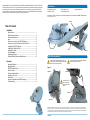
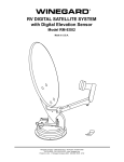
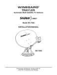
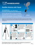
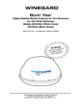
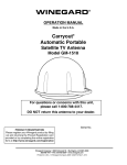
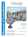
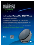
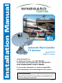
Installation Manual
Automatic Multi-Satellite
TV Antenna
Model SK-3005
DIRECTV® Slimline
www.winegard.com
For Technical Services, call 1-800-788-4417.
For Receivers and Programming, call 1-866-609-9374.
DO NOT RETURN ANTENNA TO PLACE OF PURCHASE.
For up-to-date information on receiver compatibility
and programming, visit www.winegard.com/receivers
Product Registration
Please register your Winegard product by filling out and returning the Product
Registration Card provided or by completing the online registration form at
http://www.winegard.com/registration.
2452237
Congratulations! You have selected the Winegard® TRAV’LER® Automatic Multi-Satellite TV Antenna. The TRAV’LER
antenna will deliver the ability to view up to five satellites at the same time with unmatched signal strength, the lowest
travel height on the market, maximum HD capabilities and easy to use functionality—just like you get at home.This
manual provides important information on the installation and operation of your TRAV’LER antenna. Please take time
to read the manual in its entirety before installing or operating your antenna.
Specifications
Height (stowed): 9.62 in
Unit Weight: 53 lbs
Width (stowed): 33 in
Shipping Weight: 74 lbs
Length (stowed): 44 in
Depending on location and receiver type, the following satellites can be accessed with the SK-3005 in Multi-sat mode:
99°, 101°, 103°, 110°, 119°.
Reflector
Table of Contents
Installation
Specifications..............................................................................................1
Safety Recommendations..........................................................................1
Clearance Requirements............................................................................2
Parts.............................................................................................................2
Choosing a Location for the TRAV’LER Antenna......................................3
Choosing a Location for Cables to Enter the Vehicle................................3
Installing the TRAV’LER Antenna...............................................................4
Installing the Cable Entry Plate..................................................................5
Installing the Cables...................................................................................5
Overall Installation......................................................................................5
Installing the Reflector................................................................................6
Winegard Mobile Products Limited Warranty...........................................6
Operation
Automatic Operation..................................................................................1
Manual Operation.......................................................................................2
DIRECTV Receiver Setup...........................................................................3
Ready to Travel?.........................................................................................4
Emergency Manual Stow...........................................................................4
Emergency Power Off................................................................................5
Other Notes................................................................................................5
Receivers Compatible with SWM Technology..........................................5
Troubleshooting........................................................................................6
LNB
Screw Hole
Arm
Roller
Safety Recommendations
Do not attempt to install this system in the rain
or under any wet conditions. Moisture may affect
electronics and void your warranty.
Do not paint this antenna. Painting the TRAV’LER
antenna will void your warranty.
Figure 1
Top View
Side View
Pay attention to the
pinch points as the
antenna raises. See
Figure 1.
Pinch Point
Pinch Point
Disclaimer: Although every effort has been made to ensure that the information in this manual is correct and complete, no company shall be
held liable for any errors or omissions in this manual. All information contained in this manual is subject to change without notice. No warranty
of any kind is made with regard to the information included in this manual. The satellite interface is designed specifically for use with motorized
recreational vehicles, and information contained herein is provided for that purpose only.
Installation
1
Clearance Requirements
Choosing a Location for the TRAV’LER Antenna
The arm of the TRAV’LER antenna extends 33” from the center of the base and may operate only 10” above the
surface to which the TRAV’LER antenna is mounted. To ensure you have adequate clearance for the TRAV’LER
antenna to safely operate, check that there are no obstructions taller than 10” within 33” of the center of the base.
Also, check that there are no obstructions (such as tree limbs) above the antenna that will prevent it from raising. At
its highest point, the antenna will extend to 37.5” above the roof to which it is mounted. See Figure 2.
For best performance and to reduce signal acquisition time, park the vehicle on a level surface that is free of
obstructions such as trees or large buildings. Make sure you have a clear view of the southern sky.
Before removing the TRAV’LER antenna from its box, contact your RV dealer or manufacturer. Your RV may be
pre-wired or have a reinforced area for this system.
Choose a location on the roof of the RV that meets the following requirements:
Figure 3
o
ct
ot Yet A
r (N
t
1 Offers enough support for a secure installation
2 Allows dish to raise and rotate without
interference from other roof-mounted equipment
ta
)
ed
ch
Re
fle
Top View
3 Has a minimum roof space of 44” x 33” for
antenna (Figure 3)
Center of Base
f le
cto
ch
ed
)
33”
Re
37.5” from roof to highest point of antenna
10” from roof to arm
Figure 2
tt a
r (Not Yet A
44”
Winegard is NOT liable for damage, expenses, or
injury caused by improper installation.
33” from end of arm to center of base
4 Lacks obstructions taller than 9” mounted within a
33” radius from the center of the TRAV’LER base
5 Has a gap of less than 3/16” between the bottom
of the antenna and the roof
(Do not install the TRAV’LER antenna in
a location where a gap of 3/16” or more
exists between the bottom of the antenna
and the roof, as the antenna may damage
the roof)
6 Is within 5 degrees of level, or the system may
require more time to locate satellites (for best
operation, must be within 3 degrees of level)
Choosing a Location for Cables to Enter the Vehicle
Once you have chosen a location for the TRAV’LER antenna, choose a location for the cables to enter the vehicle.
Keep in mind the following:
1 The TRAV’LER interface box must plug into a
well-ventilated 110 V outlet.
Parts
Mount Base with 30’ Power/Control Cable
TRAV’LER Power Supply
TRAV’LER Interface Box
Figure 4
2 The 24” AC power cord must be long enough to extend
from the outlet to the TRAV’LER power supply, which
will then connect to the TRAV’LER interface box.
3 The 30’ control cable must be long enough to extend
from the TRAV’LER mount base to the interface box.
Mounting Screw (20)
Reflector
Do not run wires through the striped area shown in
Figure 4. Anything in the striped area will interfere
with the operation of the TRAV’LER antenna and
may cause damage to the object or to the TRAV’LER
antenna.
5/16” Reflector Nut (4)
24” AC power cord
30’ Gray Coax Cable
30’ Black Coax Cable
5/16” Reflector Bolt (4)
2
Make sure cables are long enough to reach their destination points inside the vehicle.
For cable runs longer than 30’, an extension may be purchased. Winegard recommends using the
CL-SK26 25’ extension cable. Do not exceed 55’ of cable!
Installation
Installation
18”
4 One 30’ coax cable will need to be run from the mount
base to each receiver inside the vehicle.
Note: the provided coax cables only include a
connector on one end.
Cable Entry Plate
24”
CL-SK26
Sold Separately
3
Installing the TRAV’LER Antenna
Installing the Cable Entry Plate
Place the TRAV’LER antenna on the roof where you plan to install it. On the TRAV’LER mount base, the transition plate
is marked “FRONT” and “BACK.” Rotate the TRAV’LER antenna until the front of the TRAV’LER base faces the front of
the RV. The TRAV’LER antenna must be mounted on or parallel to the centerline of the coach. See Figure 5.
Figure 5
No obstructions taller than
10” in a 33” radius
Figure 8
Drill a 1/2” hole in the roof, and push the power/control cable and one coax cable per
receiver through the hole. (Installations for multiple receivers may require a larger hole or
multiple holes because each receiver requires a dedicated coax cable.)
33
”
Place the supplied cable entry plate over the hole and cables. Screw the plate in place
using eight of the supplied mounting screws. See Figure 8. Seal the plate and screw holes
with approved sealant (not included).
Depending on the length of the cable on the roof, you may need to use cable clamps
between the unit and the cable entry plate. Clamping every 12–16” should eliminate any
unnecessary cable movement.
Front of RV
FRONT
Mount on or parallel to
centerline of coach
After installing the TRAV’LER antenna mount base, install a cable entry plate at the location
chosen for cables to enter the vehicle from the roof, following the instructions below.
Centerline of Coach
Installing the Cables
Transition Plate
Connect the power/control cable to the TRAV’LER interface box, as shown below in Figure 9. Attach the TRAV’LER
power supply to the TRAV’LER interface box, and attach the AC power cord to the TRAV’LER power supply.
SKA-004
When installing the TRAV’LER antenna on a rubber roof, Winegard recommends using the
SKA-004 Roller Plate, which is designed to create a solid landing area for the roller. If not using
this plate, make sure that the roller does not come in contact with any rib supports or bubbles
in the roof when in operation. Failure to do so may result in damage to the roof.
Figure 9
110 V outlet
Back of TRAV’LER Interface Box
AC Power Cord
Sold Separately
Verify that the marked “FRONT” of the transition plate is facing the front of the vehicle (Figure 5).
Figure 6
Place marks through the nine holes in the mount base to mark the
location where the screw holes will go. The arrows in Figure 6
indicate the location of the nine screw holes. It is important that you
can see these marks on the roof of the RV. Move the TRAV’LER mount
out of the installation area.
It is recommended that you do not pre-drill the screw holes at
this time.
Screw hole
(not shown)
under here
To prevent water from getting into the TRA’VLER, use a solid line of
approved sealant to connect the marks in the shape of the base. This
step must be completed, or the unit will fail due to corrosion. Replace
the TRAV’LER antenna base.
S
Receiver
TRA
Pow V’LER
er Su
pply
Cable
Entry
Plate
al
al
Se
TRAV’LER
Interface Box
al
Se a
l Seal
Sea
l
Se
Lip of Transition Plate
Two coax cables must run from
the antenna to a DVR receiver.
Coax Cable
Seal Seal
Coax Cable
Se
al
t B as e
S ea
al
Se
eal
4
AV’LER M
TR
o
110 V
Outlet
Se
Run a solid bead of sealant around the edge where the transition plate
meets the roof, making sure to cover each screw head. Be careful not to
get any sealant above the lip of the transition plate. See Figure 7.
Figure 10
lS
Then, screw the antenna base to the roof using nine mounting screws.
TV
a
Se
Before using the supplied mounting screws, check with your
vehicle manufacturer for any special screw requirements.
Overall Installation
l
l
ea
eal
al S
Se
Finally, connect a coax cable from the TRAV’LER mount base to each receiver being used with the TRAV’LER antenna.
Note that two coax cables must run from the TRAV’LER antenna to a DVR receiver. Plug in the AC power cord to
the outlet. Note: the provided coax cables only include a connector on one end.
un
Figure 7
6
TRAV’LER Power Supply
Power/Control Cable
TV
DVR
Receiver
The SK-3005 will support up to four receivers.
It can support more receivers with a DIRECTV multi-switch.
Installation
Installation
5
Installing the Reflector
Once the sealant around the cable entry plate has begun to cure, check that there is nothing above the unit that
might prevent the antenna from raising. Follow the steps below to raise the antenna for reflector installation. In some
cases you may be able to install the reflector with the unit in the stowed position; if so, skip to step 3.
Pay attention to the pinch points as the antenna raises. Refer to Figure 1 on page 1 of Installation.
1
Press [POWER], and hold for two seconds to turn on the TRAV’LER interface box. Wait until the interface box
finishes “connecting to antenna.” The TRAV’LER antenna may enter the search routine after ten seconds.
2
As the antenna raises, press [POWER] and [SELECT] at the
same time. The antenna should stop moving.
3 Line up the four holes on the reflector with the four holes on
the mounting bracket. Insert the four reflector bolts through
the four holes on the front of the reflector. Thread a nut onto
each bolt, and tighten the nuts.
Figure 11
Travel Position
4 Press [POWER] until the interface displays “Stowing...”; this
should lower the antenna to the travel position (Figure 11).
WINEGARD MOBILE PRODUCTS LIMITED WARRANTY
(2 YEARS PARTS; 1 YEAR LABOR)
Winegard Company warrants this product against defects in materials or workmanship for a period of two (2) years from the date of original purchase. During year one (1)
of such warranty, Winegard Company will also pay authorized labor costs to an authorized Winegard dealer to repair or replace defective products. No warranty claim will
be honored unless at the time the claim is made, Customer presents proof of purchase to an authorized Winegard dealer (to locate the nearest authorized Winegard dealer,
contact Winegard Company, 3000 Kirkwood Street, Burlington, Iowa 52601, Telephone 800-288-8094 or visit www.winegard.com). Customer must provide proof of purchase
with a dated sales receipt for the Winegard product to verify the product is under warranty. If the date of purchase cannot be verified, the warranty period shall be considered
to begin thirty (30) days after the date of manufacture.
If a defect in material or workmanship is discovered, Customer may take the product to an authorized Winegard dealer for service. Customer must provide proof of purchase
to verify the product is under warranty. If the product is brought to an authorized Winegard dealer for service prior to expiration of year one (1) of the warranty period and a
defect in material or workmanship is verified by Winegard Technical Services, Winegard Company will cover the Winegard dealer’s labor charges for warranty service. The
Winegard dealer must contact Winegard Technical Services in advance for pre-approval of the service. Approval of the service is at the sole discretion of Winegard Company.
Alternatively, Customer may ship the product prepaid to Winegard Technical Services (located at 3111 Kirkwood Street, Burlington, Iowa 52601, Telephone 800-788-4417).
Customer must return the product along with a brief description of the problem and provide Winegard Technical Services with Customer’s name, address, and phone number.
Customer must also provide proof of purchase to verify the product is under warranty. If the product is returned before the expiration of the warranty period, Winegard Company
will (at its option) either repair or replace the product.
This Limited Warranty does not apply if the product has been damaged, deteriorates, malfunctions or fails from: improper installation, misuse, abuse, neglect, accident,
tampering, modification of the product as originally manufactured by Winegard in any manner whatsoever, removing or defacing any serial number, usage not in accordance with
product instructions or acts of nature such as damage caused by wind, lightning, ice or corrosive environments such as salt spray and acid rain. This Limited Warranty also does
not apply if the product becomes unable to perform its’ intended function in any way as a result of the television signal provider making any changes in technology or service.
RETURN AUTHORIZATION POLICY
A Return Material Authorization (RMA) is required prior to returning any product to Winegard Company or Winegard Warranty Services under this warranty policy. Please
call our Technical Services Department at 800-788-4417 or send an e-mail to [email protected] to obtain the RMA number. Please furnish the date of purchase when
requesting an RMA number. Enclose the product in a prepaid package and write the RMA number in large, clear letters on the outside of the package. To avoid confusion or
misunderstanding, a shipment(s) without an RMA number(s) or an unauthorized return(s) will be refused and returned to Customer freight collect.
WINEGARD COMPANY DOES NOT ASSUME ANY LIABILITIES FOR ANY OTHER WARRANTIES, EXPRESS OR IMPLIED, MADE BY ANY OTHER PERSON.
ALL OTHER WARRANTIES WHETHER EXPRESS, IMPLIED OR STATUTORY INCLUDING WARRANTIES OF FITNESS FOR A PARTICULAR PURPOSE AND MERCHANTABILITY
ARE LIMITED TO THE TWO YEAR PERIOD OF THIS WARRANTY.
In states that do not allow limitations on implied warranties, or the exclusion of limitation of incidental or consequential damages, the above limitations or exclusions do not apply.
Some states do not allow limitations on how long an implied warranty lasts, or the exclusion of limitation of incidental or consequential damages, so the above limitations
or exclusions may not apply to you.
This warranty gives Customer specific legal rights. Customer may also have other rights that may vary from state to state.
SATELLITE RECEIVER WARRANTY
See manufacturer’s limited warranty policy.
WS-MOBWARREV2
Rev. 1/10
Winegard Company • 3000 Kirkwood St. • Burlington, IA 52601-2000
1-800/788-4417 • FAX 319/754-0787 • www.winegard.com • Printed in U.S.A.
©2012 Winegard Company Rev2 4/12 2452237
Winegard and TRAV’LER are registered trademarks of Winegard Company.
DIRECTV is a registered trademark of DIRECTV, Inc., a unit of Hughes Electronics Corp.
6
Installation
Operation Manual
Automatic Multi-Satellite
TV Antenna
Model SK-3005
DIRECTV® Slimline
www.winegard.com
For Technical Services, call 1-800-788-4417.
For Receivers and Programming, call 1-866-609-9374.
DO NOT RETURN ANTENNA TO PLACE OF PURCHASE.
For up-to-date information on receiver compatibility
and programming, visit www.winegard.com/receivers
Product Registration
Please register your Winegard product by filling out and returning the Product
Registration Card provided or by completing the online registration form at
http://www.winegard.com/registration.
2452237
Automatic Operation
The TRAV’LER interface offers a simple one button operation. The steps below show the screens that will be
displayed as the TRAV’LER Automatic Multi-Satellite Antenna searches for satellites during operation. This one
button operation is used for both general operation and for setting up the receiver.
1
2
WINEGARD COMPANY
POWER ON
Table of Contents
Installation
Specifications..............................................................................................1
Safety Recommendations..........................................................................1
Clearance Requirements............................................................................2
Parts.............................................................................................................2
Choosing a Location for the TRAV’LER Antenna......................................3
Choosing a Location for Cables to Enter the Vehicle................................3
Installing the TRAV’LER Antenna...............................................................4
Installing the Cable Entry Plate..................................................................5
Installing the Cables...................................................................................5
Overall Installation......................................................................................5
Installing the Reflector................................................................................6
Winegard Mobile Products Limited Warranty...........................................6
Press and hold [POWER] for two
seconds or until the TRAV’LER interface
displays “POWER ON.”
3
Now that the power is on, release the
[POWER] button.
4
LG DTV Slimline
Ready: Multi-Sat
LG DTV Slimline
Searching...
The TRAV’LER antenna will enter the search
mode as part of its normal operation.
The TRAV’LER interface will try to
determine the type of dish that it is
working with. The TRAV’LER interface
will display the type of satellite dish on
the top line.
Operation
Automatic Operation..................................................................................1
Manual Operation.......................................................................................2
DIRECTV Receiver Setup...........................................................................3
Ready to Travel?.........................................................................................4
Emergency Manual Stow...........................................................................4
Emergency Power Off................................................................................5
Other Notes................................................................................................5
Receivers Compatible with SWM Technology..........................................5
Troubleshooting........................................................................................6
connecting to
antenna
5
6
LG DTV Slimline
Home EL
The TRAV’LER will find its home position.
Then, it will begin to look for a satellite.
When the TRAV’LER antenna finds a
satellite, it will fine-tune or “peak” on the
signal and determine which satellites have
been found. Once the TRAV’LER knows
which satellites have been found, it moves
to the correct satellite(s).
LG DTV Slimline
*101 *110 *119
In automatic search mode, the
TRAV’LER antenna will lock onto three
different satellites.
As the antenna finishes searching,
the TRAV’LER antenna will display an
asterisk for each satellite found.
TIP
If you want to turn off the power to the TRAV’LER antenna after the antenna has locked onto satellites, press
[POWER] and [SELECT] at the same time. Before traveling, make sure to press [POWER] and wait for antenna
to start to power up. Then press [POWER] again to initiate the stow sequence. See page 4 for more information on
stowing before traveling.
Continue to page 3 if setting up the receiver for the first time or if setting up the receiver after moving the receiver
from the house to the RV. If the receiver is already set up in the RV, you are now ready to watch TV!
Operation
1
DIRECTV Receiver Setup
Manual Operation
The following instructions assume that the TRAV’LER antenna has found and locked onto
satellites 101°, 110°, 119°, 99° and 103°. There should be an asterisk next to 101°, 110°, and 119°
on the TRAV’LER interface.
The TRAV’LER antenna is a versatile satellite antenna and can be manually set to find many different satellites
individually. Note: this function is rarely used. The instructions below assume that the TRAV’LER antenna is already in
the stowed position.
In most DIRECTV receivers, the setup is done through the “Repeat Satellite Setup” option in
your receiver manual. The following instructions are based on an H24 receiver. If your receiver
differs from the options shown, you may need to consult your receiver manual. The wording
and display used in your receiver may differ slightly.
2
1
WINEGARD COMPANY
POWER ON
Press and hold [POWER] for two
seconds or until the TRAV’LER interface
displays “POWER ON.”
3
For Help, Call 1-800-788-4417.
Enter User Menu?
*Yes No
1
Press Menu on
your remote,
and then select
Parental, Fav’s &
Setup.
2
Select System
Setup.
3
In your receiver
Menu, you will
need to identify
the Satellite
Menu. The
Satellite Menu
will have an
option for
Satellite Setup.
4
You may be
required to press
the DASH (-)
before proceeding
(underneath #7
on the remote).
Set Dish Type for
04: Slimline-5.
Set the Switch
Type for
02: Multiswitch.
6
Your installation
will be verified.
8
Select Continue.
Press and hold the [ENTER] button for
two seconds.The TRAV’LER interface
will ask if you wish to enter the User
Menu. Press [SELECT] to choose “Yes,”
and then press [ENTER].
4
Search Mode*
Diagnostics
Multi-Sat Mode*
Manual 61
The User Menu consists of four choices:
Search Mode, Diagnostics, Installation,
and Exit.
Once in the Search Menu, you may
choose from the following: MULTISAT
MODE (normal search mode),
MANUAL 101, MANUAL 110, MANUAL
119, MAIN MENU (returns to the User
Menu), or EXIT (enters the search
routine).
Note: Diagnostic and Installation menus
are not required for normal operation
and should only be entered by a trained
professional.
Press [SELECT] to cycle through these
satellites until the asterisk is next to the
satellite you wish to find. Then, press
[ENTER] to select a satellite.
Press [ENTER] to choose Search Mode.
5
Press Continue.
5
6
Manual ##
Selected
The TRAV’LER interface will ask you
to confirm the change. Press [SELECT]
to move the asterisk to “Yes,” and then
press [ENTER]. The TRAV’LER interface
will then acknowledge which satellite
has been selected. Press [ENTER].
2
Power OFF?
*Yes No
The TRAV’LER interface will ask if
you want to turn the power off. Press
[ENTER] to choose “No” and start a new
search for your chosen satellite. Press
[SELECT] then [ENTER] to choose “Yes”
and turn off the antenna.
The TRAV’LER antenna will remain
in manual mode until you select
“Multi-Sat Mode” again.
Operation
7
Errors may be
displayed on
the Installation
Status screen.
This is normal to
see one or two
boxes with an X
instead of a .
Continue with
step 9 on the next
page.
Select Continue.
Operation
Disclaimer: Receiver setup instructions are accurate at time of printing and may change without notice. Call Winegard tech line for assistance: 1-800-788-4417.
3
Receiver Setup, Continued
Emergency Power Off
The program
guide will
download.
9
The receiver will
run Data Feed and
Guide Feed Tests
for a few moments.
10
When the status
bar reaches
100%, press
Continue.
The Winegard TRAV’LER antenna comes with an Emergency Power Off feature. To activate it, press and hold
[POWER] and then press [SELECT] while still holding [POWER]. The TRAV’LER antenna will stop and turn off.
If the Emergency Power Off feature is used, the TRAV’LER antenna may not be in a safe position for travel.
Do not move the vehicle until you are able to stow the unit. See Ready to Travel? above.
Other Notes
Weather and vehicle location can impact the ability of the TRAV’LER antenna to locate all of the required satellites.
Obstructions such as buildings or tree limbs can block the satellite signals and prevent the TRAV’LER antenna from
successfully locating all of the satellites for Multi-Sat Mode. Make sure you have a clear view of the southern sky.
You will be
prompted to set
up the remote.
Select Setup
Remote Later to
do this at a later
time.
11
Select
Watch DIRECTV.
12
Receivers Compatible with SWM Technology
Winegard mobile satellite TV antennas operate with Multi-switch technology and require separate accessories to
operate with DIRECTV Single Wire Multi-switch (SWM) only technology receivers.
For an up-to-date list of DIRECTV DVR and non-DVR receiver models that are only compatible with SWM technology,
visit www.winegard.com/directv. This website also lists Winegard mobile satellite TV antennas that are compatible
with DIRECTV.
You are now ready to watch TV!
If unsure of your receiver model, check the back of the receiver or the inside front door of the smart card slot.
Model Number
Ready to Travel?
The TRAV’LER antenna is not meant for use while traveling.
To stow the unit when you are ready to travel, press [POWER] one time.
The unit will stop what it is doing and return to the stowed position.
Stowed/Travel Position
If you have a SWM only technology receiver, Winegard Model SWM-840 SWM kit is available. This SWM kit will allow
for proper SWM technology operation with Winegard mobile satellite TV antennas.
The TRAV’LER interface will not turn off unless the TRAV’LER mount is
successfully stowed. Visually inspect that the antenna is in the stowed/
travel position before traveling.
Do not move the vehicle until the TRAV’LER antenna is stowed.
www.winegard.com
Emergency Manual Stow
Technical Services, call 1-800-788-4417.
Emergency manual stow is meant as a last resort and is not meant for common usage!
For Receivers, call 1-866-609-9374.
Unplug the TRAV’LER interface. Then, remove the black plastic bolt from the back of the mount. Insert a 3/8th socket
extension into this auxiliary drive. Turn the auxiliary drive clockwise to lower the unit. Do not use a drill!
For up-to-date information on receiver compatibility and programming,
visit www.winegard.com/receivers.
4
Operation
Operation
5
Troubleshooting
ANTENNA CONNECTION
FAILED
Check the data cable connection on the back of the TRAV’LER interface box. It may
not be connected properly.
EL HOME FAILURE
Something is preventing the TRAV’LER mount from raising as it attempted to find
the HOME position. Look for obstructions if unit has recently been manually raised
or if the electronics have been replaced. The calibration may need to be reset.
Contact Winegard Technical Support 1-800-788-4417.
AZ MOTOR STALLED
Something is preventing the TRAV’LER mount from rotating; look for obstructions. If
there is no obvious obstruction, contact Winegard Technical Support at 1-800-788-4417.
EL MOTOR STALLED
Something is preventing the TRAV’LER mount from raising or lowering; look
for obstructions. If there is no obvious obstruction, contact Winegard Technical
Support at 1-800-788-4417.
SK MOTOR STALLED
Something is preventing the TRAV’LER reflector and LNBF from rotating; look
for obstructions. If there is no obvious obstruction, contact Winegard Technical
Support at 1-800-788-4417.
STOW FAILURE
ANT NOT STOWED
The TRAV’LER antenna is not stowed. Do not try to move the vehicle. Try to stow
the TRAV’LER antenna again. If it fails again, check for obstructions.
STOW FAILURE
STOW UNKNOWN
Check the data cable connection on the back of the TRAV’LER interface. It may not
be connected properly.
AZ MOTOR RUN REVERSE
Contact Winegard Technical Support at 1-800-788-4417.
EL MOTOR RUN REVERSE
Contact Winegard Technical Support at 1-800-788-4417.
SK MOTOR RUN REVERSE
Contact Winegard Technical Support at 1-800-788-4417.
AZ MOTOR RUNAWAY
Contact Winegard Technical Support at 1-800-788-4417.
EL MOTOR RUNAWAY
Contact Winegard Technical Support at 1-800-788-4417.
SK MOTOR RUNAWAY
Contact Winegard Technical Support at 1-800-788-4417.
NO LNB VOLTAGE
The TRAV’LER antenna is not seeing the required 12–18 VDC needed to power
the LNBF. Check the coax connections. If these are all connected properly, contact
Winegard Technical Support at 1-800-788-4417.
UNKNOWN ERROR
######
Contact Winegard Technical Support at 1-800-788-4417.
C MOTOR NOT FOUND
Contact Winegard Technical Support at 1-800-788-4417.
NOT RECEIVING 99 and 103
Make sure the B-Band Converter is installed.
ANTENNA WILL NOT
AUTOMATICALLY STOW.
See emergency manual stow instructions on page 4 of the operation manual.
Weather and vehicle location can impact the ability of the TRAV’LER antenna to locate all of the required satellites.
Obstructions such as buildings or tree limbs can block the satellite signals and prevent the TRAV’LER antenna from
successfully locating all of the satellites for Multi-Sat Mode. Make sure you have a clear view of the southern sky.
6
Operation