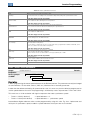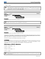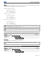
1
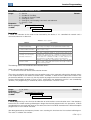
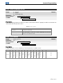
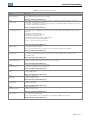
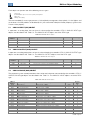
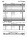
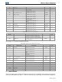
Motors I Automation I Energy I Transmission & Distribution I Coatings BACnet CFW-11 User’s Manual BACnet User’s Manual Series: CFW-11 Language: English Document Number: 10000831662 / 03 Publication Date: 02/2014 Contents CONTENTS CONTENTS ...............................................................................................................................3 ABOUT THE MANUAL .............................................................................................................5 ABBREVIATIONS AND DEFINITIONS........................................................................................... 5 NUMERICAL REPRESENTATION ................................................................................................ 5 DOCUMENTS ............................................................................................................................ 5 1 INTRODUCTION TO THE SERIAL COMMUNICATION ................................................ 6 2 BACNET COMMUNICATION ACCESSORY ................................................................... 7 2.1 RS485 .............................................................................................................................. 7 2.1.1 RS485-01 Kit .............................................................................................................. 7 2.1.2 CAN/RS485-01 Kit ...................................................................................................... 7 2.1.3 Connector Pinout ....................................................................................................... 7 2.1.4 Indications and Switches............................................................................................ 8 2.1.5 Connection with the RS485 Network ........................................................................... 8 2.2 ANYBUS-CC .................................................................................................................... 8 3 INTRODUCTION TO THE BACNET COMMUNICATION .............................................. 9 3.1 BACNET MS/TP.............................................................................................................. 10 3.1.1 BACnet MS/TP Message Structure............................................................................ 10 3.2 ADDRESS ...................................................................................................................... 12 3.3 BACNET PROFILE .......................................................................................................... 12 3.3.1 ReadProperty (DS-RP-B) .......................................................................................... 12 3.3.2 WriteProperty (DS-WP-B).......................................................................................... 12 3.3.3 WHO IS / I AM (DM-DDB-B)....................................................................................... 12 3.3.4 Device Management-Time Synchronization-B (DM-TS-B) ........................................... 12 3.3.5 Device Management-Reinitialize Device-B (DM-RD-B) ............................................... 12 4 INVERTER PROGRAMMING ..........................................................................................13 4.1 SYMBOLS FOR THE PROPERTIES DESCRIPTION ............................................................ 13 P0105 – 1ST/2ND RAMP SELECTION ............................................................................................ 13 P0220 – LOCAL/REMOTE SELECTION SOURCE ........................................................................ 13 P0221 – SPEED REFERENCE SELECTION – LOCAL SITUATION.................................................. 13 P0222 – SPEED REFERENCE SELECTION – REMOTE SITUATION ............................................... 13 P0223 – FORWARD/REVERSE SELECTION – LOCAL SITUATION ................................................ 13 P0224 – RUN/STOP SELECTION – LOCAL SITUATION................................................................ 13 P0225 – JOG SELECTION – LOCAL SITUATION.......................................................................... 13 P0226 – FORWARD/REVERSE SELECTION – REMOTE SITUATION ............................................. 13 P0227 – RUN/STOP SELECTION – REMOTE SITUATION ............................................................. 13 P0228 – JOG SELECTION – REMOTE SITUATION ....................................................................... 13 P0308 – SERIAL ADDRESS ....................................................................................................... 13 P0310 – SERIAL BAUD RATE .................................................................................................... 14 P0311 – SERIAL INTERFACE BYTE CONFIGURATION ................................................................ 14 P0312 – SERIAL PROTOCOL..................................................................................................... 14 P0313 – COMMUNICATION ERROR ACTION.............................................................................. 15 P0314 – SERIAL WATCHDOG.................................................................................................... 15 P0316 – SERIAL INTERFACE STATUS ....................................................................................... 16 P0680 – STATUS WORD ........................................................................................................... 16 P0681 – MOTOR SPEED IN 13 BITS........................................................................................... 18 P0682 – SERIAL CONTROL WORD ............................................................................................ 18 P0683 – SERIAL SPEED REFERENCE ........................................................................................ 19 P0696 – VALUE 1 FOR ANALOG OUTPUTS ................................................................................ 20 CFW-11 | 3 Contents P0697 – VALUE 2 FOR ANALOG OUTPUTS ................................................................................ 20 P0698 – VALUE 3 FOR ANALOG OUTPUTS ................................................................................ 20 P0699 – VALUE 4 FOR ANALOG OUTPUTS ................................................................................ 20 P0760 – BACNET EQUIPMENT INSTANCE – HIGH PART............................................................. 21 P0761 – BACNET EQUIPMENT INSTANCE – LOW PART ............................................................. 21 P0762 – MAXIMUM MASTER NUMBER...................................................................................... 22 P0763 – MAXIMUM NUMBER OF MS/TP FRAMES...................................................................... 22 P0764 – I AM TRANSMISSION ................................................................................................... 23 P0765 – NUMBER OF RECEIVED TOKENS................................................................................. 23 5 BACNET OBJECT MODELING ......................................................................................24 5.1 ANALOG INPUT (ANI) OBJECT ........................................................................................ 25 5.2 ANALOG OUTPUT (ANO) OBJECT ................................................................................... 25 5.3 ANALOG VALUE (ANV) OBJECT ...................................................................................... 25 5.3.1 MBOX...................................................................................................................... 26 5.4 BINARY INPUT (BIN) OBJECT ......................................................................................... 26 5.5 BINARY OUTPUT (BOUT) OBJECT................................................................................... 27 5.6 BINARY VALUE (BV) OBJECT.......................................................................................... 27 5.7 DEVICE OBJECT ............................................................................................................ 28 6 FAULTS AND ALARMS RELATED TO THE SERIAL COMMUNICATION................. 29 A128/F228 – TIMEOUT FOR SERIAL COMMUNICATION ............................................................. 29 CFW-11 | 4 About the Manual ABOUT THE MANUAL The BACnet communication protocol is available in the CFW-11 frequency inverter special software version (Ve) 5.3x. This version is derived from the standard version 5.1X, with the following modifications: The CANopen, Profibus and DeviceNet communication protocol has been removed; The BACnet MS/TP and SymbiNet communication protocol has been added. This manual provides the necessary information for the operation of the CFW-11 frequency inverter using the BACnet protocol. This manual must be used together with the CFW-11 user manual. ABBREVIATIONS AND DEFINITIONS ASCII PLC HMI ro rw American Standard Code for Information Interchange Programmable Logic Controller Human-Machine Interface Read-only Read/write NUMERICAL REPRESENTATION Decimal numbers are represented by means of digits without suffix. Hexadecimal numbers are represented with the letter ‘h’ after the number. DOCUMENTS The BACnet protocol for the CFW-11 was developed based on the following specifications and documents: Document Standard 135-2004 Version 1.0 Source ANSI/ASHRAE/ISO In order to obtain this documentation, consult BACnet ORG, witch is the organization that currently maintains, publishes and updates the information regarding the BACnet network. CFW-11 | 5 Introduction to the Serial Communication 1 INTRODUCTION TO THE SERIAL COMMUNICATION In a serial interface, the data bits are sent sequentially through a communication channel, or busbar. Several technologies use serial communication for data transfer, including the RS232 and RS485 interfaces. The standards that specify the RS232 and RS485 interfaces, however, do specify neither the format nor the character sequence for data transmission and reception. In this sense, besides the interface, it is also necessary to identify the protocol used for the communication. The BACnet MS/TP network defines the BACnet message exchange using the RS485 interface as the physical layer. The characteristics of the RS485 serial interfaces available in the CFW-11 frequency inverter, as well as the BACnet protocol, will be presented next. CFW-11 | 6 BACnet Communication Accessory 2 BACNET COMMUNICATION ACCESSORY In order to make a BACnet interface available for the CFW-11 frequency inverter, it is necessary to use one of the RS485 communication kits described next. Information on the installation of these modules in the frequency inverter can be obtained in the guide that comes with the kit. 2.1 RS485 The CFW-11 presents two options for using the RS485 interface, described next. 2.1.1 RS485-01 Kit 2.1.2 CAN/RS485-01 Kit 2.1.3 WEG part number: 10051957. Composed by the RS485 communication module (drawing at the left), mounting instructions and fixing screw. The interface follows the EIA-485 standard. It allows baud rates from 9600 bits/s to 57600 bit/s. The interface is electrically isolated and with differential signal, which grants more robustness against electromagnetic interference It allows the connection of up to 32 devices to the same segment. More devices can be connected by using repeaters. 1 A maximum bus length of 1000 meters. WEG part number: 10051960. Composed by the CAN/RS485-01 communication module (drawing at the left), mounting instruction and fixing screw. It has the same characteristics as the RS485-01 interface, plus a CAN interface, for applications where the operation with both interfaces is necessary. Connector Pinout The RS485 communication module presents a 4-wire plug-in terminal strip (XC7) with the following pinout: Table 2.1: 4-wire RS485 terminal strip pinout Terminal 1 2 3 Name A-Line (-) B-Line (+) GND 4 Ground Function RxD/TxD negative RxD/TxD positive 0V isolated from the RS485 circuit Terra (shield) 1 The limit number of devices that can be connected to the network depends also on the used protocol. CFW-11 | 7 BACnet Communication Accessory 2.1.4 Indications and Switches 2.1.5 TX LED: LED for the indication of data transmission by the frequency inverter, in green color. Termination resistor (S1): switch for enabling the termination resistor, necessary for the RS485 interface. This resistor must be enabled (position ON) only at the devices located at the extremes of the main bus. Connection with the RS485 Network The following points must be observed for the connection of the frequency inverter using the RS485 interface: 2.2 It is recommended the use of a shielded cable with a twisted pair of wires. It is also recommended that the cable has one more wire for the connection of the reference signal (GND). In case the cable does not have the additional wire, then the GND signal must be left disconnected. The cable must be laid separately (and far away if possible) from the power cables. All the network devices must be properly grounded, preferably at the same ground connection. The cable shield must also be grounded. Enable the termination resistors only at two points, at the extremes of the main bus, even if there are derivations from the bus. ANYBUS-CC The RS485 interface can also be made available by using the passive Anybus-CC kit available for RS485. Refer to the Anybus-CC Communication Manual for information on this kit. CFW-11 | 8 Introduction to the BACnet Communication 3 INTRODUCTION TO THE BACNET COMMUNICATION BACnet, acronym for "Building Automation Control Network", is a protocol defined by the ANSI/ASHRAE/ISO Standard 135-2004. The protocol defines a model for building-automation, describing the interaction between devices and systems. The protocol defines: Data and commands structured in an object-oriented model; Services that describe the access to data; A flexible network architecture. The BACnet standard defines six types of communication networks for transporting BACnet messages, as showed in the Figure 3.1. The type of network defines the physical and data link layers. The six types of networks are: BACnet BACnet BACnet BACnet BACnet BACnet ARCnet; Ethernet; Lontalk; MS/TP; Point-to-Point; IP; Figure 3.1: BACnet protocol architecture A BACnet equipment contains an information collection defined as objects and properties. A BACnet object represents physical or virtual information of the equipment, as a digital or analog input, control variables and parameters. The BACnet standard defines 25 types of objects. Each object is identified by a propriety called Object Identifier, which codifies the object instance type in a 32-bit binary number. A BACnet property represents characteristics or information of a BACnet object. It is through the properties that other elements can access the equipment information. The property access can be defined as read-only or writing/reading. The BACnet specification defines services that are grouped in five categories: Object access Device Management Alarm and event File transfer Virtual terminal BACnet equipments can be classified in six different profiles according to the set of services made available: BACnet BACnet BACnet BACnet BACnet BACnet Operator Workstation (B-OWS) Building Controller (B-BC) Advanced Application Controller (B-AAC) Application Specific Controller (B-ASC) Smart Actuator (B-AS) Smart Sensor (B-SS) CFW-11 | 9 Introduction to the BACnet Communication 3.1 BACNET MS/TP In the CFW-11, the BACnet protocol was developed using the RS485 standard for the physical and data link layers, called BACnet MS/TP (Master Slave/Token Passing). BACnet MS/TP nodes can be divided into two groups, master nodes and slave nodes, according to the node address range. The access control to the communication mean is performed in two ways: Master/Slave (MS): It is used in the communication between a master node and a slave node; Token passing (TP): Communication only among master nodes. A logical ring is defined and the master that has the token can establish communication with slave nodes and other masters. In a BACnet MS/TP network, the nodes are initialized and enter the IDLE state, waiting for the arrival of a telegram, which can be: Invalid frame: it remains in IDLE; Not desired frame: it remains in IDLE; Token: it enters the USE TOKEN state, executes the necessary communication (with slaves or other masters) and passes the token to the next node; Reception of a Poll of Master: it sends a telegram to the node with the address in the Source Address field; Reception of a DataNoReplay: it signalizes the reception to the higher layers; Reception of a DataNeedingReplay: it signalizes the reception to the higher layers and sends the requested response. 3.1.1 BACnet MS/TP Message Structure The BACnet specification defines that the frame can have from 0 up to 501 bytes (octets), and that each byte is composed by 8 bits without parity, with start and stop bits, as showed in the Figure 3.2. Figure 3.2: Byte structure Reception (RX): The maximum time between bytes (Tframegap) is of 20-bit times, and the minimum time between frames (Tturnaround) after the last byte stop bit is of 40-bit times, according to the Figure 3.3. Transmission (TX): The RTS signal must be disabled after the end of the stop bit time (Tpostdrive), which is of 15-bit times. Figure 3.3: BACnet data reception Header and data, as Figure 3.4 illustrates, form the BACnet data frame. CFW-11 | 10 Introduction to the BACnet Communication 0x55 0xFF Frame type HEADER Destination Source address address DATA Length Length CRC Data CRC CRC Figure 3.4: BACnet Frame Preamble: It is formed by two bytes with the 55h and FFh values respectively. Frame type: The BACnet specification defines eight frame types, from 0 to 7. Frame Types 8 through 127 are reserved for the specification improvement, and from 128 through 255 are reserved for each vendor specific frames. The defined types are: 0 Token 1 Poll for master 2 Reply to poll for master 3 Test request 4 Test response 5 BACnet data expecting reply 6 BACnet data not expecting reply 7 Reply postponed Only master nodes must acknowledge frame types 0, 1 and 2, the slave nodes must ignore them. Token (0) frame type: it is used in the relationship between master nodes. It does not present data. The master node that has the token can initiate the communication. After sending the maximum number of data frames (Nmax_info_frames) and waiting any expected replies, it must pass the token to the next master. Poll for Master (1) frame type: It is transmitted periodically during the configuration. It is used to discover the presence of other masters in the network and to determine the token sequence. Master nodes must respond and slave nodes must ignore it. It does not present data. Reply to Poll for Master (2) frame type: It is the response of the master nodes to the Poll for Master (frame type 1). It does not present data. Test Request (3) frame type: It is used to start the communication in the MS/TP network. It is applied to send a particular piece of information to a node. Test Response (4) frame type: It is the response to a Test Request. BACnet Data Expecting Reply (5) frame type: It is used by master nodes to convey the data parameter of a DL_UNITDATA.request that presents destination address, data, priority and message code, waiting for a response from the destination node. BACnet Data not Expecting Reply (6) frame type: It is used by master nodes to convey the data parameter of a DL_UNITDATA.request that presents destination address, data, priority and message code. It does not wait for a response from the destination node. Reply Postponed (7) frame type: It is used by master nodes to indicate that the response to a Data Expecting Reply frame will be sent later. It does not present data. Destination and source addresses: It is formed by two bytes, destination and source, respectively. Length: It is formed by two bytes that inform the number of data bytes in the message. Header CRC: The last part of the header is the fields for checking header transmission errors. The used method is the CRC-8 (Cycling Redundancy Check). Data: It may present from 0 to 501 bytes, according to the BACnet specification. Data in the CFW-11 can present up to 59 bytes. Data CRC: The last part of the telegram is the field for checking data transmission errors. The used method is the CRC-16 (Cycling Redundancy Check). CFW-11 | 11 Introduction to the BACnet Communication 3.2 ADDRESS It presents an address range from 0 to 254, where: The range from 0 to 127 is reserved for master or slave nodes; The range from 128 to 254 is used only by slave nodes. The broadcast telegram must have FFh (255) in the destination address field. The serial address is set using parameter P0308 in the CFW-11. 3.3 BACNET PROFILE The BACnet profile developed for the CFW-11 is the B-ASC, with communication management services and data sharing that presents the following BIBBs (BACnet interoperability Building Blocks): DATA SHARING: DS-RP-B: ReadProperty; DS-WP-B: WriteProperty. DEVICE and NETWORK MGMT: DM-DDB-B: WHO IS / I AM; DM-TS-B: Device Management-Time Synchronization-B DM-RD-B: Device Management-Reinitialize Device-B. 3.3.1 ReadProperty (DS-RP-B) A BACnet client (node performing a request to a server node) uses the ReadProperty service to obtain a BACnet object property value. This service allows reading access to the properties that have the R (reading) access type. 3.3.2 WriteProperty (DS-WP-B) A BACnet client uses the WriteProperty service to modify the value of a specific BACnet object property. This service allows writing access to the properties that have the W (write) or C (commandable) access type. 3.3.3 WHO IS / I AM (DM-DDB-B) The WHO IS / I AM service is used to identify the devices connected to the network. The WHO IS message is sent by the BACnet controller, and the nodes respond with an I AM message, informing their Object Identifier and address. The I AM message is transmitted in broadcast, and can be transmitted during initialization or continuous, according to the parameter P0764. 3.3.4 Device Management-Time Synchronization-B (DM-TS-B) The Time Synchronization service implemented in the CFW-11 executes date and time updating according to the received date and time. 3.3.5 Device Management-Reinitialize Device-B (DM-RD-B) The Reinitialize Device service is used to remotely reinitialize the equipment, and uses a password to validate the service execution. The BACnet standard defines that the password is a string (set of ASCII characters) with up to 20 positions. The password used for the CFW-11 remote reinitialization is the same one used to allow the access for parameter content modifications, informed in the parameter P0000. This password can be a number between 0000 and 9999. The BACnet password for the CFW-11 is a 4-character string. Therefore, the BACnet password can be a number between 0000 and 9999. E.g., considering that the CFW-11 default password is 5, the remote reinitialization service will only be executed if the received password is “0005”. CFW-11 | 12 Inverter Programming 4 INVERTER PROGRAMMING Next, only the CFW-11 frequency inverter parameters related to the BACnet communication will be presented. 4.1 SYMBOLS FOR THE PROPERTIES DESCRIPTION RO CFG Net Serial USB Read-only parameter Parameter that can be changed only with a stopped motor Parameter visible on the HMI if the inverter has the network interface installed – RS232, RS485, CAN, Anybus-CC, Profibus – or if the USB interface is connected Parameter visible on the HMI if the inverter has the RS232 or RS485 interface installed Parameter visible on the HMI if the inverter USB interface is connected P0105 – 1ST/2ND RAMP SELECTION P0220 – LOCAL/REMOTE SELECTION SOURCE P0221 – SPEED REFERENCE SELECTION – LOCAL SITUATION P0222 – SPEED REFERENCE SELECTION – REMOTE SITUATION P0223 – FORWARD/REVERSE SELECTION – LOCAL SITUATION P0224 – RUN/STOP SELECTION – LOCAL SITUATION P0225 – JOG SELECTION – LOCAL SITUATION P0226 – FORWARD/REVERSE SELECTION – REMOTE SITUATION P0227 – RUN/STOP SELECTION – REMOTE SITUATION P0228 – JOG SELECTION – REMOTE SITUATION These parameters are used in the configuration of the command source for the CFW-11 frequency inverter local and remote situations. In order that the device be controlled through the BACnet interface, the options ‘serial’ available in these parameters, must be selected. The detailed description of these parameters is found in the CFW-11 programming manual. P0308 – SERIAL ADDRESS Range: 0 to 255 Properties: CFG Access groups 01 PARAMETER GROUPS via HMI: ∟ 49 Communication ∟ 113 Serial RS232 / 485 Default: 1 Description: It allows programming the address used for the inverter serial communication. It is necessary that each device in the network has an address different from all the others. The valid addresses for this parameter depend on the protocol programmed in P0312: P0312 = 1 (TP) → valid addresses: 1 to 30. P0312 = 2 (Modbus-RTU) → valid addresses: 1 to 247. P0312 = 3 (BACnet MS/TP)→ valid addresses: 0 to 254. NOTE! The equipment must be initialized when the serial address is changed and the BACnet protocol selected. CFW-11 | 13 Inverter Programming P0310 – SERIAL BAUD RATE Range: 0 = 9600 bits/s 1 = 19200 bits/s 2 = 38400 bits/s 3 = 57600 bits/s Properties: CFG Access groups 01 PARAMETER GROUPS via HMI: ∟ 49 Communication ∟ 113 Serial RS232 / 485 Default: 1 Description: It allows programming the baud rate for the serial communication interface, in bits per second. This baud rate must be the same for all the devices connected to the network. P0311 – SERIAL INTERFACE BYTE CONFIGURATION Range: 0 = 8 data bits, no parity, 1 stop bit 1 = 8 data bits, even parity, 1 stop bit 2 = 8 data bits, odd parity, 1 stop bit 3 = 8 data bits, no parity, 2 stop bits 4 = 8 data bits, even parity, 2 stop bits 5 = 8 data bits, odd parity, 2 stop bits Properties: CFG Access groups 01 PARAMETER GROUPS via HMI: ∟ 49 Communication ∟ 113 Serial RS232 / 485 Default: 1 Description: It allows programming the number of data bits, parity and stop bits of the serial interface bytes. This configuration must be identical for all the devices connected to the network. NOTE! The option 0 (default) must be selected for the BACnet protocol. P0312 – SERIAL PROTOCOL Range: 1 = TP 2 = Modbus RTU 3 = BACnet MS/TP Properties: CFG Access groups 01 PARAMETER GROUPS via HMI: ∟ 49 Communication ∟ 113 Serial RS232 / 485 Default: 2 Description: It allows selecting the desired protocol for the serial interface. CFW-11 | 14 Inverter Programming P0313 – COMMUNICATION ERROR ACTION Range: 0 = Inactive 1 = Disable via Run/Stop 2 = Disable via General Enable 3 = Change to Local 4 = Change to Local keeping commands and reference 5 = Causes a Fault Properties: CFG Access groups 01 PARAMETER GROUPS via HMI: ∟ 49 Communication ∟ 111 Status and commands Default: 1 Description: It allows the selection of the action to be executed by the device, if it is controlled via network and a communication error is detected. Table 4.1: P0313 options Options 0 = Inactive 1 = Disable via Run/Stop 2 = Disable via General Enable 3 = Change to Local 4 = Change to Local keeping commands and reference 5 = Causes a Fault Description No action is taken and the drive remains in the existing status. A stop command with deceleration ramp is executed and the motor stops according to the programmed deceleration ramp. The drive is disabled by removing the General Enabling and the motor coasts to stop. The drive commands change to Local. The drive commands change to Local, but the status of the enabling and speed reference commands received via network are kept, providing that the drive has been programmed to use in Local mode the commands via HMI, or 3-wire start/stop and speed reference via either HMI or electronic potentiometer. Instead of an alarm, the communication error causes an drive fault, so that a drive fault reset becomes necessary in order to restore normal operation. The following events are considered communication errors: Serial communication (RS232/RS485): A128 alarm/F228 fault: Serial communication timeout The actions described in this parameter are executed by means of the automatic writing of the selected actions in the respective bits of the interface control words. Therefore, in order that the commands written in this parameter be effective, it is necessary that the device be programmed to be controlled via the used network interface (with exception of option “Causes a Fault”, which blocks the equipment even if it is not controlled by network). This programming is achieved by means of parameters P0220 to P0228. P0314 – SERIAL WATCHDOG Range: 0.0 to 999.0s Properties: CFG Access groups 01 PARAMETER GROUPS via HMI: ∟ 49 Communication ∟ 111 Status and commands Default: 0.0 Description: It allows programming a time limit for the detection of serial interface communication error. If the frequency inverter remains without receiving valid telegrams longer than the time programmed in this parameter, it will be considered that a communication error has occurred, the alarm A128 will be showed on the HMI and the option programmed in P0313 will be executed. After being powered up, the frequency inverter starts counting this time from the first received valid telegram. The value 0.0 disables this function. CFW-11 | 15 Inverter Programming P0316 – SERIAL INTERFACE STATUS Range: Default: - 0 = Inactive 1 = Active 2 = Watchdog error Properties: RO Access groups 01 PARAMETER GROUPS via HMI: ∟ 49 Communication ∟ 111 Status and commands Description: It allows identifying whether the RS232 or RS485 serial interface board is properly installed, and whether the serial communication presents errors. Table 4.2: P0316 options Options Description Inactive serial interface. It occurs when the device does not have the RS232 or RS485 board installed. Installed and acknowledged RS232 or RS485 interface board. The serial interface is active, but a serial communication error has been detected - A128 alarm/F228 fault. 0 = Inactive 1 = Active 2 = Watchdog error P0680 – STATUS WORD Range: 0000h to FFFFh Properties: RO Access groups 01 PARAMETER GROUPS via HMI: ∟ 49 Communication ∟ 111 Status and commands Default: - 15 14 13 12 11 10 9 8 7 6 5 4 Function (PID) Automatic Undervoltage LOC/REM JOG Speed direction Active General Enable Motor Running Alarm condition In configuration mode Second ramp Active fast stop 3 to 0 Reserved Bits Fault condition Description: It allows the device status monitoring. Each bit represents a specific status: CFW-11 | 16 Inverter Programming Table 4.3: P0680 parameter bit functions Bits Bits 0 to 3 Bit 4 Active quick stop Bit 5 Second ramp Bit 6 In configuration mode Values Reserved. 0: The fast stop command is not active. 1: The drive is executing the fast stop command. This bit is mapped in the BV4 object 0: The drive is configured to use the first ramp values, programmed in P0100 and P0101, as the motor acceleration and deceleration ramp times. 1: The drive is configured to use the second ramp values, programmed in P0102 and P0103, as the motor acceleration and deceleration ramp times. This bit is mapped in the BV5 object 0: The drive is operating normally. 1: The drive is in the configuration mode. It indicates a special condition during which the drive cannot be enabled: Executing the self-tuning routine Executing the oriented start-up routine Executing the HMI copy function Executing the flash memory card self-guided routine There is a parameter setting incompatibility There is no power at the drive power section Bit 7 Alarm condition This bit is mapped in the BV6 object 0: The drive is not in alarm condition. 1: The drive is in alarm condition. Note: The alarm number can be read by means of the parameter P0048 – Present Alarm. Bit 8 Motor Running This bit is mapped in the BV7 object 0: The motor is stopped. 1: The drive is running the motor at the set point speed, or executing either the acceleration or the deceleration ramp. Bit 9 Active General Enable This bit is mapped in the BV8 object 0: General Enable is not active. 1: General Enable is active and the drive is ready to run the motor. Bit 10 Speed direction This bit is mapped in the BV9 object 0: The motor is running in the reverse direction. 1: The motor is running in the forward direction. Bit 11 JOG This bit is mapped in the BV10 object 0: Inactive JOG function. 1: Active JOG function. Bit 12 LOC/REM This bit is mapped in the BV11 object 0: Drive in Local mode. 1: Drive in Remote mode. Bit 13 Undervoltage This bit is mapped in the BV12 object 0: No Undervoltage. 1: With Undervoltage. Bit 14 Manual/ Automatic This bit is mapped in the BV13 object 0: PID in manual mode. 1: PID in Automatic mode. Bit 15 Fault condition This bit is mapped in the BV14 object 0: The drive is not in a fault condition. 1: The drive has detected a fault. Note: The fault number can be read by means of the parameter P0049 – Present Fault. This bit is mapped in the BV15 object CFW-11 | 17 Inverter Programming P0681 – MOTOR SPEED IN 13 BITS Range: - 32768 to 32767 Properties: RO Access groups 01 PARAMETER GROUPS via HMI: ∟ 49 Communication ∟ 111 Status / Commands Default: - Description: It allows monitoring the motor speed. This word uses 13-bit resolution with signal to represent the motor synchronous speed: P0681 = 0000h (0 decimal) P0681 = 2000h (8192 decimal) → motor speed = 0 → motor speed = synchronous speed Intermediate or higher speed values in rpm can be obtained by using this scale. E.g. for a 4 pole motor and 1800 rpm of synchronous speed if the value read is 2048 (0800h), then, to obtain the speed in rpm one must calculate: 8192 => 1800 rpm 2048 => Speed in rpm Speed in rpm = 1800 × 2048 8192 Speed in rpm = 450 rpm Negative values in this parameter indicate that the motor is running in the reverse direction. This parameter is mapped in the ANV28 object. P0682 – SERIAL CONTROL WORD Range: 0000h to FFFFh Properties: Access groups 01 PARAMETER GROUPS via HMI: ∟ 49 Communication ∟ 111 Status and commands Default: 0000h Description: It is the device BACnet interface control word. This parameter can only be changed via serial interface. For the other sources (HMI, etc.) it behaves like a read-only parameter. In order to have those commands executed, it is necessary to program the equipment to be controlled via serial. This programming is achieved by means of parameters P0105 and P0220 to P0228. 7 6 5 4 3 2 Function Fault reset Quick stop Second ramp LOC/REM JOG Speed direction 1 0 Run/Stop 15 to 8 General enable Bits Reserved Each bit of this word represents a command that can be executed. CFW-11 | 18 Inverter Programming Table 4.4: P0682 parameter bit functions Bit 0 Run/Stop Bits Values 0: It stops the motor with deceleration ramp. 1: The motor runs according to the acceleration ramp until reaching the speed reference value. Bit 1 General enable This bit is mapped in the object BV16 0: It disables the drive, interrupting the supply for the motor. 1: It enables the drive allowing the motor operation. Bit 2 Speed direction This bit is mapped in the object BV17 0: To run the motor in a direction opposed to the speed reference. 1: To run the motor in the direction indicated by the speed reference. Bit 3 JOG This bit is mapped in the object BV18 0: It disables the JOG function. 1: It enables the JOG function. Bit 4 LOC/REM This bit is mapped in the object BV19 0: The drive goes to the Local mode. 1: The drive goes to the Remote mode. Bit 5 Second ramp Bit 6 Quick stop This bit is mapped in the object BV20 0: The drive uses the first ramp values, programmed in P0100 and P0101, as the motor acceleration and deceleration ramp times. 1: The drive is configured to use the second ramp values, programmed in P0102 and P0103, as the motor acceleration and deceleration ramp times. This bit is mapped in the object BV21 0: It does not execute the quick stop command. 1: It executes the quick stop command. Note: This function is not allowed with control types (P0202) V/f or VVW. Bit 7 Fault reset This bit is mapped in the object BV22 0: No function. 1: If in a fault condition, then it executes the reset. Bits 8 to 15 This bit is mapped in the object BV23 Reserved. P0683 – SERIAL SPEED REFERENCE Range: -32768 to 32767 Properties: Access groups 01 PARAMETER GROUPS via HMI: ∟ 49 Communication ∟ 111 Status and commands Default: 0 Description: It allows programming the motor speed reference via the BACnet interface. This parameter can only be changed via serial interface. For the other sources (HMI, etc.) it behaves like a read-only parameter. In order that the reference written in this parameter be used, it is necessary that the drive be programmed to use the speed reference via serial. This programming is achieved by means of parameters P0221 and P0222. This word uses a 13-bit resolution with signal to represent the motor synchronous speed. P0683 = 0000h (0 decimal) P0683 = 2000h (8192 decimal) → speed reference = 0 → speed reference = synchronous speed Intermediate or higher reference values can be programmed by using this scale. E.g. for a 4 pole motor and 1800 rpm of synchronous speed, to obtain a speed reference of 900 rpm one must calculate: CFW-11 | 19 Inverter Programming 1800 rpm => 8192 900 rpm => 13 bit reference 13 bit reference = 900 × 8192 1800 => Value corresponding to 900 rpm in a 13 bit scale 13 bit reference = 4096 This parameter also accepts negative values to revert the motor speed direction. The reference speed direction, however, depends also on the control word - P0682 - bit 2 setting: Bit Bit Bit Bit 2= 2= 2= 2= 1 and P0683 > 1 and P0683 < 0 and P0683 > 0 and P0683 < 0: 0: 0: 0: reference reference reference reference for forward direction for reverse direction for reverse direction for forward direction This parameter is mapped in the ANV29 object. P0696 – VALUE 1 FOR ANALOG OUTPUTS P0697 – VALUE 2 FOR ANALOG OUTPUTS P0698 – VALUE 3 FOR ANALOG OUTPUTS P0699 – VALUE 4 FOR ANALOG OUTPUTS Range: -32768 to 32767 Properties: Access groups 01 PARAMETER GROUPS via HMI: ∟ 49 Communication ∟ 111 Status and commands Default: 0 Description: They allow the control of the analog outputs by means of network interfaces (Serial, CAN, etc.). These parameters cannot be changed via HMI. The value written in these parameters is used as the analog output value, providing that the function for the desired analog output be programmed for “P0696 / P0697 / P0698 / P0699 value”, at the parameters P0251, P0254, P0257 or P0260. The value must be written in a 15-bit scale (7FFFh = 32767) 2 to represent 100 % of the output desired value, i.e.: P0696 = 0000h (0 decimal) → analog output value = 0 % P0696 = 7FFFh (32767 decimal) → analog output value = 100 % The showed example was for P0696, but the same scale is also used for the parameters P0697 / P0698 / P0699. For instance, to control the analog output 1 via serial, the following programming must be done: Choose a parameter from P0696, P0697, P0698 or P0699 to be the value used by the analog output 1. For this example, we are going to select P0696. Program the option “P0696 value” as the function for the analog output 1 in P0254. Using the network interface, write in P0696 the desired value for the analog output 1, between 0 and 100 %, according to the parameter scale. BACnet objects of the ANALOG OUTPUT type mold the analog outputs, where: ANO0 - P0696. ANO1 - P0697. ANO2 - P0698. 2 For the actual output resolution, refer to the product manual. CFW-11 | 20 Inverter Programming ANO3 - P0699. NOTE! If the analog output is programmed for working from -10 V to 10 V, negative values for this parameter must be used to command the output with negative voltage values, i.e., -32768 to 32767 represent a variation from -10 V to 10 V at the analog output. P0760 – BACNET EQUIPMENT INSTANCE – HIGH PART Range: 1 a 247 Properties: CFG Access groups 01 Parameter Groups via HMI: ∟ 49 Communication ∟ 113 Serial RS232 / 485 Default: 1 Description: It defines the high part of the BACnet equipment instance. NOTE! Refer to the parameter P0761 description for more details. P0761 – BACNET EQUIPMENT INSTANCE – LOW PART Range: 0 to 9999 Properties: CFG Access groups 01 Parameter Groups via HMI: ∟ 49 Communication ∟ 113 Serial RS232 / 485 Default: 0 Description: It defines the low part of the BACnet equipment instance. The BACnet standard defines that the equipment instance must be unique in the network and it must present a value between 0 and 4194304. The BACnet instance will compose the Object Identifier property of the DEVICE object, which defines the equipment characteristics in the network. The BACnet instance can be defined automatically or manually: Automatically: If the values of parameters P0760 and P0761 are set 0 (default value), the inverter will automatically create the BACnet instance based on the vendor BACnet ID (WEG BACnet ID = 359) and the serial address. For this configuration, the user must only inform the serial address at the parameter P0308. BACnet instance = BACnet ID + Serial address Example 1: serial address = 102 Instance = 359102 Example 2: serial address = 15 Instance = 359015 NOTE! The instance created automatically is not showed at the parameters P0760 and P0761, which remain with the value 0. CFW-11 | 21 Inverter Programming Manual: The BACnet instance is defined by using the parameters P0760 and P0761. The P0760 parameter content is multiplied by 10000 and added to the P0761 parameter content. Example 1: Instance = 542786 542786 / 10000 = 54.2786 P760 = 54 (whole part) P761 = 2786 (fractional part) Example 2: Instance = 66789 66789 / 10000 = 6.6789 P760 = 6 (whole part) P761 = 6789 (fractional part) Example 3: Instance = 35478 35478 / 10000 = 3.5478 P760 = 3 (whole part) P761 = 5478 (fractional part) NOTE! The parameters P0760 and P0761 allow adjusting a maximum value of 4199999. However, the maximum instance value will be 4194304. NOTE! The equipment must be initialized when the contents of parameters P0760 and P0761 are changed. P0762 – MAXIMUM MASTER NUMBER Range: 0 to 127 Properties: CFG Access groups 01 Parameter Groups via HMI: ∟ 49 Communication ∟ 113 Serial RS232 / 485 Default: 127 Description: It defines the highest allowable address for master nodes. NOTE! The equipment must be initialized when the content of the parameter P0762 is changed. P0763 – MAXIMUM NUMBER OF MS/TP FRAMES Range: 1 to 65535 Properties: CFG Access groups 01 Parameter Groups via HMI: ∟ 49 Communication ∟ 113 Serial RS232 / 485 Default: 1 CFW-11 | 22 Inverter Programming Description: It defines the number of telegrams that the node can transmit when it receives the token. Then it must transmit the token to the next node. NOTE! The equipment must be initialized when the content of the parameter P0763 is changed. P0764 – I AM TRANSMISSION Range: 0 = Power Up 1 = Continuous Properties: RO Access groups 01 Parameter Groups via HMI: ∟ 49 Communication ∟ 113 Serial RS232 / 485 Default: 0 Description: The I AM telegram is used to identify the node in the BACnet network. When the option 1, periodically, is selected, then an I AM telegram is sent every 200 ms. NOTE! The equipment must be initialized when the content of the parameter P0764 is changed. P0765 – NUMBER OF RECEIVED TOKENS Range: 0 to 65535 Properties: RO Access groups 01 Parameter Groups via HMI: ∟ 49 Communication ∟ 113 Serial RS232 / 485 Default: - Description: It is the counter of the number of tokens received from other BACnet nodes. It allows the serial communication verification. CFW-11 | 23 BACnet Object Modeling 5 BACNET OBJECT MODELING A BACnet object represents physical or virtual equipment information, as a digital input or parameters. The CFW-11 presents the following object types: ANALOG INPUT; ANALOG OUTPUT; ANALOG VALUE; BINARY INPUT; BINARY OUTPUT; BINARY VALUE; DEVICE OBJECT. Each object type defines a data structure composed by properties that allow the access to the object information. The Table 5.1 shows the implemented properties for each CFW-11 object type. Table 5.1: Properties of the BACnet objects Property Object Identifier Object Name Object Type System Status Vendor Name Vendor Identifier Model Name Firmware Revision Application Software Version Description Protocol Version Protocol Revision Protocol service supported Protocol object types Supported Object List Max APDU Len Accepted Segmentation Supported APDU timeout Number of APDU retries Max Master Max info frames Device Address Binding Database revision DEVICE X X X X X X X X X X X X X X X X X X X X X X X Present Value Status Flags Event State Out of Service Units Priority Array Relinquish Default ANALOG INPUT ANALOG OUTPUT ANALOG VALUE BINARY INPUT BINARY OUTPUT BINARY VALUE X X X X X X X X X X X X X X X X X X X X X X X X X X X X X X X X X X X X X X X X X X X X X X X X X X X X X X X X X X Polarity * The Priority Array and Relinquish Default properties are available for objects with type C (commandable) access. Each object presents an identifier unique in the network, called Object Identifier. The Object Identifier property is composed by two parts: Object Type – 10 bits Object instance– 22 bits CFW-11 | 24 BACnet Object Modeling Each object can present one of the following access types: R C W W/R Read-only Commandable object. Presents a priority arrangement Write-only Writing and reading The commandable (C) access type presents a 16-level priority arrangement, where priority 1 is the highest and 16 the lowest. If all the priorities are disabled (NULL), the value of the Relinquish Default property is given to the Present Value property. 5.1 ANALOG INPUT (ANI) OBJECT It represents an analog input that can have its value read by the controller. CFW-11 ANALOG INPUT type objects are described in the Table 5.2. The ANALOG INPUT objects are of the REAL type Table 5.2: ANALOG INPUT objects Object instance ANI0 5.2 Object name Description Unit Access type AI1 Value Accesses the contents of the parameter P0018 % R ANI1 AI2 Value Accesses the contents of the parameter P0019 % R ANI2 AI3 Value Accesses the contents of the parameter P0020 % R ANI3 AI4 Value Accesses the contents of the parameter P0021 % R ANALOG OUTPUT (ANO) OBJECT It represents an analog output that can have its value written by the controller. CFW-11 ANALOG OUTPUT type objects are described in the Table 5.3. The ANALOG OUTPUT objects are of the REAL type Table 5.3: ANALOG OUTPUT objects Object instance ANO0 ANO1 ANO2 ANO3 5.3 Object name AO1 AO2 AO3 AO4 Value Value Value Value Description Accesses Accesses Accesses Accesses the the the the contents contents contents contents of of of of the parameter P0696 the parameter P0697 the parameter P0698 the parameter P0699 Unit Access type - C C C C ANALOG VALUE (ANV) OBJECT They represent system control parameters that can be read, written or commanded by the controller. CFW-11 ANALOG VALUE type objects are described in the Table 5.4. The ANALOG VALUE objects are of the REAL type Table 5.4: ANALOG VALUE objects Object instance ANV0 ANV1 ANV2 ANV3 ANV4 ANV5 ANV6 ANV7 ANV8 ANV9 ANV10 ANV11 ANV12 ANV13 ANV14 ANV15 ANV16 ANV17 ANV18 Object name Motor Speed Motor Current DC Link Voltage (Ud) Motor Frequency Motor Voltage Motor Torque Output Power IGBTs Temperature U IGBTs Temperature V IGBTs Temperature W Rectifier Temperature Internal Air Temp PID Process Variable PID Setpoint Value Time Powered Time Enabled kWh Output Energy Fan Enabled Time Present Alarm Description Motor speed – P0002 Motor current – P0003 DC link voltage – P0004 Motor frequency – P0005 Motor voltage – P0007 Motor torque – P0009 Output power – P0010 Temperature of the U IGBTs – P0030 Temperature of the V IGBTs – P0031 Temperature of the W IGBTs – P0032 Temperature of the rectifier – P0033 Temperature of the internal air – P0034 PID process variable value – P0040 PID setpoint value – P0041 Number of inverter powered hours – P0042 Number of inverter enabled hours – P0043 Counter of the output KWh – P0044 Fan enabled time – P0045 Present alarm – P0048 Unit RPM Amps V Hz V % KW °C °C °C °C °C % % H H H H - Access type R R R R R R R R R R R R R R R R R R R CFW-11 | 25 BACnet Object Modeling ANV19 ANV20 ANV21 ANV22 ANV23 ANV24 ANV25 ANV26 ANV27 ANV28 ANV29 ANV30 ANV31 ANV32 ANV33 ANV34 ANV35 ANV36 ANV37 Present Fault Last Fault Acceleration Time Deceleration Time PID Proportional Gain PID Integral Gain PID Differential Gain Keypad PID Setpoint Wake Up Band Speed in 13 bits Serial/USB Speed Ref. MBOX parameter MBOX data SoftPLC Parameter 1 SoftPLC Parameter 2 SoftPLC Parameter 3 SoftPLC Parameter 4 SoftPLC Parameter 5 SoftPLC Parameter 6 Present fault – P0049 Last fault – P0050 Acceleration time – P0100 Deceleration time – P0101 PID proportional gain –P0520 PID integral gain – P0521 PID differential gain – P0522 PID keypad setpoint– P0525 PID wake up band – P0535 Motor speed in 13 bits - P0681 Speed reference via serial – P0683 MBOX parameter MBOX data SoftPLC parameter 1 – P1010 SoftPLC parameter 2 – P1011 SoftPLC parameter 3 – P1012 SoftPLC parameter 4 – P1013 SoftPLC parameter 5 – P1014 SoftPLC parameter 6 – P1015 s s % % % - R R C C C C C C C R C W/R W/R C C C C C C The CFW-11 programming manual presents the detailed description of each parameter. 5.3.1 MBOX It is a structure that allows reading and writing CFW-11 parameters. The following objects compose this structure: ANV30: informs the parameter number ANV31: informs the datum read from or written into the parameter BV33: parameter reading command BV34: parameter writing command Procedure for reading a parameter via MBOX: 1. Inform the parameter number in the ANV30 object Present Value property; 2. Write 1 in the BV33 object Present Value property; 3. Check the value read in the ANV31 object Present Value property. The read value will be an integer, without the decimal point representation. E.g., 20.0 will be read as 200 in the MBOX. Procedure for writing a parameter via MBOX: 1. Inform the parameter number in the ANV30 object Present Value property; 2. Inform the value to be written in the parameter in the ANV31 object Present Value property. The value to be written must be an integer, without the decimal point representation. E.g., 20.0 must be written as 200 in the MBOX. 3. Write 1 in the BV34 object Present Value property. 5.4 BINARY INPUT (BIN) OBJECT It represents a physical digital input that can have its status read by the controller. CFW-11 BINARY INPUT type objects are described in the Table 5.5 and in the Table 5.6. The Table 5.5 describes the BIN objects for the parameter P0012 bits, and the Table 5.6 describes the BIN objects for the parameter P0013 bits. Table 5.5: Parameter P0012 BINARY INPUT objects Object instance Object name BIN0 DI1 Status BIN1 DI2 Status BIN2 DI3 Status BIN3 DI4 Status BIN4 DI5 Status Description DI1 digital input status (P0012 parameter BIT 0) DI2 digital input status (P0012 parameter BIT 1) DI3 digital input status (P0012 parameter BIT 2) DI4 digital input status (P0012 parameter BIT 3) DI5 digital input status Active/ inactive Access type ON/OFF R ON/OFF R ON/OFF R ON/OFF R ON/OFF R CFW-11 | 26 BACnet Object Modeling BIN5 DI6 Status BIN6 DI7 Status BIN7 DI8 Status BIN8 BIN9 BIN10 BIN12 BIN13 BIN14 BIN15 Reserved Reserved Reserved Reserved Reserved Reserved Reserved (P0012 parameter BIT 4) DI6 digital input status (P0012 parameter BIT 5) DI7 digital input status (P0012 parameter BIT 6) DI8 digital input status (P0012 parameter BIT 7) ON/OFF R ON/OFF R ON/OFF R Active/ inactive Access type ON/OFF R ON/OFF R ON/OFF R ON/OFF R ON/OFF R Table 5.6: Parameter P0013 BINARY INPUT objects Object instance 5.5 Object name BIN16 DO1 Status BIN17 DO2 Status BIN18 DO3 Status BIN19 DO4 Status BIN20 DO5 Status BIN21 BIN22 BIN23 BIN24 BIN25 BIN26 BIN28 BIN29 BIN30 BIN31 BIN32 Reserved Reserved Reserved Reserved Reserved Reserved Reserved Reserved Reserved Reserved Reserved Description DO1 digital output status (P0013 parameter BIT 0) DO2 digital output status (P0013 parameter BIT 1) DO3 digital output status (P0013 parameter BIT 2) DO4 digital output status (P0013 parameter BIT 3) DO5 digital output status (P0013 parameter BIT 4) BINARY OUTPUT (BOUT) OBJECT It represents a physical digital output that can have its status changed by the controller. CFW-11 BINARY OUTPUT type objects are described in the Table 5.7. Table 5.7: BINARY OUTPUT objects Object instance 5.6 Object name BOUT0 DO1 Value BOUT1 DO2 Value BOUT2 DO3 Value BOUT3 DO4 Value BOUT4 DO5 Value Description DO1 digital output (P0695 parameter BIT 0) DO2 digital output (P0695 parameter BIT 1) DO3 digital output (P0695 parameter BIT 2) DO4 digital output (P0695 parameter BIT 3) DO5 digital output (P0695 parameter BIT 4) Active/inactiv e Access type ON/OFF C ON/OFF C ON/OFF C ON/OFF C ON/OFF C BINARY VALUE (BV) OBJECT They represent system control parameter bits that can be read, written or commanded by the controller. CFW11 BINARY VALUE type objects are described in the Table 5.8, Table 5.9 and Table 5.10. Table 5.8: Parameter P0680 BINARY VALUE objects Object instance BV0 BV1 Object name Description Unit Access type Reserved Reserved CFW-11 | 27 BACnet Object Modeling BV2 BV3 BV4 Reserved Reserved Reserved BV5 2nd Ramp Select BV6 In configuration mode BV7 Alarm condition BV8 Ramp Enabled (RUN) BV9 General Enabling active BV10 Speed Direction BV11 JOG BV12 LOC/REM BV13 Undervoltage BV14 Manual/Automatic BV15 Fault condition Second ramp (P0680 parameter BIT 5) Configuration mode (P0680 parameter BIT 6) Alarm (P0680 parameter BIT 7) Enabled Ramp (P0680 parameter BIT 8) General enable (P0680 parameter BIT 9) Speed direction (P0680 parameter BIT 10) JOG (P0680 parameter BIT 11) LOC/REM (P0680 parameter BIT 12) Undervoltage (P0680 parameter BIT 13) Manual/automatic (P0680 parameter BIT 14) Fault (P0680 parameter BIT 15) ON/OFF R ON/OFF R ON/OFF R ON/OFF R ON/OFF R ON/OFF R ON/OFF R ON/OFF R ON/OFF R ON/OFF R ON/OFF R Table 5.9: MBOX BINARY VALUE objects Object instance Object name BV33 MBOX read BV34 MBOX write Description Command to read the contents of the parameter specified in the ANV30 object. Command to write the contents specified in the ANV31 object in the parameter specified in the ANV30 object. Active/inactive Access type ON/OFF W ON/OFF W The section 5.3.1 describes the MBOX operation. Table 5.10: Parameter P0682 BINARY VALUE objects Object instance 5.7 Object name BV16 Run/Stop BV17 General Enabling BV18 Direction of Rotation BV19 JOG BV20 LOC/REM BV21 Second Ramp Use BV22 Quick Stop BV23 Fault reset BV24 BV25 BV26 BV27 BV28 BV29 BV30 BV31 Reserved Reserved Reserved Reserved Reserved Reserved Reserved Reserved Description Run/stop (P0682 parameter General enable (P0682 parameter Speed direction (P0682 parameter JOG (P0682 parameter LOC/REM (P0682 parameter Second ramp (P0682 parameter Quick Stop (P0682 parameter Fault reset (P0682 parameter BIT 0) BIT 1) BIT 2) BIT 3) BIT 4) BIT 5) BIT 6) BIT 7) Active/inactiv e Access type ON/OFF C ON/OFF C ON/OFF C ON/OFF C ON/OFF C ON/OFF C ON/OFF C ON/OFF C DEVICE OBJECT The DEVICE object informs the BACnet equipment characteristics. Its properties represent those characteristics and they are described in the Table 5.1. There must be only one DEVICE object at each BACnet equipment. CFW-11 | 28 Faults and Alarms Related to the Serial Communication 6 FAULTS AND ALARMS RELATED TO THE SERIAL COMMUNICATION A128/F228 – TIMEOUT FOR SERIAL COMMUNICATION Description: It is the only alarm/fault related to the serial communication indicates that the equipment stopped receiving valid serial telegrams for a period longer than the one programmed in P0314. Operation: The parameter P0314 allows programming a period of time during which the equipment must receive at least one valid telegram via the RS232 / RS485 serial interface – with address and error-checking field correct – otherwise, it will be considered that there was any problem in the serial communication. The time counting initiates after the reception of the first valid telegram. This function can be used by any serial protocol supported by the equipment. After the serial communication timeout has been identified, the A128 alarm or F228 fault message will be showed on the HMI, depending on the P0313 programming. For alarms, if the communication is reestablished and new valid telegrams are received, the alarm indication will be removed from the HMI. Possible Causes/Correction: Verify factors that could cause failures in the communication (cables, installation, and grounding). Make sure that the master sends telegrams to the equipment in intervals shorter than the programmed in P0314. Disable this function at P0314. CFW-11 | 29 WEG Drives & Controls – Automação LTDA Jaraguá do Sul - SC - Brazil Phone 55 (47) 3276-4000 - Fax 55 (47) 3276-4020 São Paulo - SP - Brazil Phone 55 (11) 5053-2300 - Fax 55 (11) 5052-4212 [email protected] www.weg.net