1
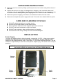
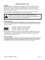
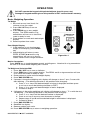
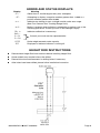
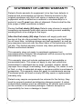
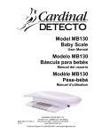
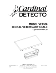
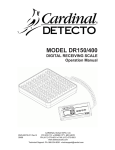
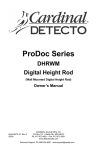
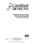
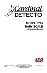
ELECTRONIC PHYSICIAN
Waist-High Scale
6027 and 6029 Series
Owner’s Manual
0044-M078-O1 Rev G
11/06
CARDINAL SCALE MFG. CO.
PO BOX 151 v WEBB CITY, MO 64870
PH (417) 673-4631 v FAX (417) 673-5001
Web Site - www.detectoscale.com
Technical Support: Ph: 866-254-8261 v [email protected]
Printed in USA
INTRODUCTION
Thank you for your purchase of our Detecto
Electronic Physician Waist-High Scale. It was
built with Detecto quality and reliability at our
factory in Webb City, Missouri. This manual
will guide you through installation, and
operation of your scale. Please read it
thoroughly before attempting to operate this
scale and keep it handy for future reference.
FCC COMPLIANCE STATEMENT
WARNING! This equipment generates uses
and can radiate radio frequency and if not
installed and used in accordance with the
instruction manual, may cause interference to
radio communications. It has been tested
and found to comply with the limits for a Class
A computing device pursuant to Subpart J of
Part 15 of FCC rules, which are designed to
provide reasonable protection against such
interference when operated in a commercial
environment. Operation of this equipment in
a residential area may cause interference in
which case the user will be responsible to
take whatever measures necessary to correct
the interference.
You may find the booklet "How to Identify and
Resolve Radio TV Interference Problems"
prepared by the Federal Communications
Commission helpful. It is available from the
U.S. Government Printing Office, Washington,
D.C. 20402. Stock No. 001-000-00315-4.
All rights reserved. Reproduction or use, without
expressed written permission, of editorial or pictorial
content, in any manner, is prohibited. No patent
liability is assumed with respect to the use of the
information contained herein. While every precaution
has been taken in the preparation of this manual, the
Seller assumes no responsibility for errors or
omissions. Neither is any liability assumed for
damages resulting from use of the information
contained herein. All instructions and diagrams have
been checked for accuracy and ease of application;
however, success and safety in working with tools
depend to a great extent upon the individual accuracy,
skill and caution. For this reason the Seller is not able
to guarantee the result of any procedure contained
herein. Nor can they assume responsibility for any
damage to property or injury to persons occasioned
from the procedures. Persons engaging the
procedures do so entirely at their own risk.
Serial Number_______________________
Date of Purchase ____________________
Purchased Form_____________________
___________________________________
___________________________________
RETAIN THIS INFORMATION FOR FUTURE USE
0044-M078-O1 v 6027 and 6029
TABLE OF CONTENTS
INTRODUCTION ……………………………
SPECIFICATIONS ………………………….
UNPACKING INSTRUCTIONS ……………
CARE AND CLEANING …………………….
INSTALLATION ……………………………..
Power Supply ………………………….....
Batteries …………………………………..
Battery Operation ...………………………
Battery Charging …..……………………..
Battery Installation/Replacement ……….
OPERATION …………………………………
ERROR AND STATUS DISPLAYS ……….
HEIGHT ROD INSTRUCTIONS …….……..
1
1
2
2
2
2
3
3
3
4
5
6
6
SPECIFICATIONS
Power ………….... 6 “AA” size Alkaline, NiRequirements
Cad or NiMH batteries
(not included) OR an
optional 100 to 240 VAC
50/60Hz 12 VDC 1A wall
plug-in UL/CSA listed
AC power supply.
Operating .……….. 14º to 104º F
Temperature
(-10º to +40º C)
Capacity .………… 400 lb x .5 lb
(180 kg x .2 kg)
Platform Size .…… 11" x 13"
Dimensions ....…… 12.5” W x 16” D x 38” H
Weight .…..….…… 17 lb (7.7kg)
PRECAUTIONS
Before using this instrument, read this
manual and pay special attention to all
"WARNING" symbols:
IMPORTANT
ELECTRICAL
WARNING
Page 1
UNPACKING INSTRUCTIONS
v
Remove scale from carton by lifting up with equal force from column and platform base of
the scale.
v
Inspect the scale for any signs of damage due to shipping, such as exterior dents and
scratches. It is the responsibility of the Purchaser to file all claims for any damages or loss
in transit incurred. Retain packing and shipping carton for return of scale if necessary.
v
Remove all plastic wrapping, foam ¿llers and cardboard material from the scale.
v
Remove and unpack the power supply and cord, if the scale was ordered with this option.
CARE AND CLEANING OF SCALE
v
v
v
v
v
v
DO NOT subject the platform to sudden shocks.
DO NOT spray water directly on the display head.
DO avoid areas where the scale might be exposed to moisture.
DO NOT use abrasive cleaners on this instrument.
DO NOT use acetone or other volatile solvents for cleaning.
DO clean the scale using a damp soft cloth and mild detergent.
INSTALLATION
Power Supply
To power the weight indicator without batteries, connect the 12 VDC, 1 Amp power supply’s
connector into the power jack on the lower back of the indicator and then plug the power
supply into the proper electrical outlet. See Figure 1. On models requiring 220 VAC, it is the
customer’s responsibility to obtain the correct power adapter plug. The scale is now ready for
operation.
NOTE! The power supply is also used to recharge the batteries, when
the weight indicator is operated from Ni-Cad or NiMH batteries.
Battery
Cover
Scale
Cable
Power
Supply
Figure No. 1
0044-M078-O1 v 6027 and 6029
Page 2
INSTALLATION, Cont.
Batteries
Battery operation is a standard feature of the weight indicator, although the batteries are
optional (not included). The indicator can be operated from 6 "AA" size Alkaline, Ni-Cad or
NiMH batteries. You must first obtain and install batteries before operations can begin.
Batteries are contained in a battery holder inside the indicator. Access is via a removable
panel on the back of the indicator.
When using batteries, all 6 batteries must be of the same type. They must be all Alkaline,
Ni-Cad or all NiMH. In addition, DO NOT mix Ni-Cad or NiMH batteries.
CAUTION! The weight indicator has internal circuitry that when used in
conjunction with the external power supply, recharges the Ni-Cad or NiMH
batteries. Because the indicator has this charging capability, DO NOT connect a
power supply to the indicator if using Alkaline batteries.
Battery Operation
The weight indicator will operate for up to 250 hours on new Alkaline batteries or for up to 100
hours on fully charged Ni-Cad or NiMH batteries depending on the condition of the batteries
(from new to about 500 recharges). The battery bar graph on the display indicates the battery
capacity in 4 steps:
4 segments - the full battery capacity is available,
3 segments - the battery is at 75% of capacity,
2 segments - the battery is at 50% of capacity,
1 segment: - the battery is at 25% capacity.
When the battery voltage drops too low for accurate weighing, the indicator will show "7<
and then shut off. You will be unable to turn the indicator back on until the Alkaline batteries
have been replaced or the AC power supply is connected to the display to operate it and
recharge the Ni-Cad or NiMH batteries.
Battery Charging
To recharge the Ni-Cad or NiMH batteries, the AC power supply must be connected to a power
outlet and plugged into the indicator. It will take approximately 8 to 10 hours to fully recharge
the batteries in the display. Charging the batteries for more than 10 hours will not damage
them. NOTE! The indicator may be operated while the batteries are charging.
0044-M078-O1 v 6027 and 6029
Page 3
INSTALLATION, Cont.
Battery Installation/Replacement
To install or remove the batteries, the following steps should be followed:
1. Remove indicator from desk
stand/wall mount bracket if used.
2. Turn the indicator so that the display
is facing away from you.
Push in and
lift here
Battery
Cover
3. Locate the rectangular panel on back
of indicator.
4. To install or replace the batteries, first
remove the battery holder cover by
pushing in on the tab and lifting it up.
Refer to Figure No. 2.
5. If installing new batteries, proceed to
step 6. If replacing the batteries,
remove all 6 batteries from the battery
holder and then proceed to step 6.
6. Install the 6 new “AA” size batteries in
the battery holder, noting the polarity
markings located in the battery
holder. Refer to Figure No. 3.
7. After placing all 6 batteries in the
holder, replace the battery cover.
Figure No. 2
8. Make sure power supply is
unplugged, and then turn indicator
over (display facing up) and press
ON / OFF key.
9. If display turns on, batteries have
been installed correctly. If not,
remove panel and check for one or
more improperly positioned batteries.
+
-
10. Return the indicator to desk
stand/wall mount bracket if used.
+
+
-
11. The scale is now ready for operation.
+
+
-
-
+
Figure No. 3
For more information on setup and
operation of the indicator, see the 750
Owner’s Manual (8555-M260-O1).
0044-M078-O1 v 6027 and 6029
Page 4
OPERATION
DO NOT operate the keypad with pointed objects (pencils, pens, etc).
Damage to keypad resulting from this practice is NOT covered under warranty.
Basic Weighing Operation
To Weigh
1. Set scale on any hard, level, flat
surface or low-cut carpet.
2. Press ON / OFF key to turn on
indicator.
3. Press ZERO key to zero weight
display. The ZERO and lb or kg
annunciator will turn on to show that
scale is ready for use.
4. Place patient on scale and read weight
display.
5. Remove patient from scale.
Zero Weight Display
1. If the indicator is not showing zero
weight on the display, press ZERO
key.
2. Weight display will return to zero.
ZERO, STABLE [\ and lb or kg
annunciators will turn on to show a
stable, center-of-zero weight condition.
Figure No. 4
Metric Conversion
Press UNITS key to toggle between pounds and kilograms. Note that lb or kg annunciator
will turn on to show which weighing unit is active.
To Weigh and Calculate BMI
1. Press ON / OFF key to turn on indicator.
2. Press ZERO key to zero weight display. The ZERO and lb or kg annunciator will turn
on to show that scale is ready for use.
3. Place patient on scale and read weight display.
4. Press BMI / ENTER key.
5. If pounds is the active weighing unit, display will change to show FEET, INCHES with
the 6 blinking. (The blinking character is the position to be changed).
a. Press a or b keys until desired height in inches is displayed and then press
_ or ` key to move the blinking character to FEET.
b. Press a or b keys until desired height in feet is displayed.
c. Proceed to Step 7.
6. If kilograms is the active weighing unit, display will change to show cm.with the 0 of
170 blinking. (The blinking character is the position to be changed)...
a. Press a or b keys until the desired number is displayed.
b. Press _ or ` key to move to next character to change.
c. Repeat steps A and B until the desired height in centimeters is displayed.
d. Proceed to Step 7.
7. Press BMI / ENTER key.
8. Read BMI on display.
9. Remove patient from scale.
10. Press BMI / ENTER key to return to weighing operation.
0044-M078-O1 v 6027 and 6029
Page 5
ERROR AND STATUS DISPLAYS
Display
A::A
A$A
Meaning
General error, invalid keypad entry was attempted.
Attempting to display a negative number greater than –9,999 or a
positive number greater than 99,999
A<:"A
Indicates an attempt to zero a weight outside scale zero range.
(See Four Percent Zero Tracking Range Limit).
A(1+A
Motion is present when indicator is attempting to perform one of the
following operations: Power Up Zero or Zero Weight Display
".3
Indicates calibration is necessary.
4::a
::"a
::
$%
$
Consult your scale service representative.
Scale weight exceeds scale capacity
Displayed to indicate indicator is turning off.
HEIGHT ROD INSTRUCTIONS
v
Please check Height Rod hole locations before installing Height Rod.
v
Some models may require holes to be drilled.
v
Please follow the measurements for drilling holes if necessary.
v
After holes have been drilled, please follow installation instruction.
0044-M078-O1 v 6027 and 6029
Page 6
HEIGHT ROD INSTRUCTIONS, Cont.
Height Rod Installation
1. Remove Height Rod from shipping
container. Inspect for signs of damage.
Contact Detecto Customer Service
Department if necessary.
Column
Height Rod
Bracket
2. Remove cardboard insert from height rod.
3. If not already installed, insert the four hex
head screws from the hardware pack into
the holes in the back of the column and
tighten them with the included wrench until
the hex heads are 1/8" from the column.
Pre-Installed
Screws
4. Place both height rod brackets over the
four pre-installed hex head screws and pull
down, securing brackets.
5. Use the included wrench to tighten the hex
head screws. Do not over tighten screws.
Height Rod
Height Rod Operation
1. Before patient steps onto scale platform,
spoon should be rotated to horizontal
position, and raised well above patient’s
apparent height.
2. Patient may now step onto scale platform.
Spoon should be held horizontal and
above patient’s head.
A
B
C
E
D
3. Carefully lower spoon, while keeping it
horizontal, until it rests gently on top of
patient’s head. If patient is shorter than 3’
4" (101.5 cm), push latch to right while
simultaneously pushing down on spoon,
until the spoon rests horizontally on top of
patient’s head.
4. Read height of patient as follows:
If back of spoon points to outer height rod,
then it points to correct height.
If back of spoon points to inner height rod,
then correct height is read at top of outer
height rod (see "Read" arrow on outer
height rod).
Height Rod in
“rest” position
A = Latch
B = Spoon
C = Inner Height Rod
D = Outer Height Rod
E = Measurement
“Read” Line
5. While holding spoon horizontally, raise spoon above patient’s head. Patient may now step
off scale platform. Hold spoon horizontal until patient is clear of height rod.
6. Rotate spoon back to vertical position and adjust height rod back to rest position (i.e. spoon
should be locked in place within inner height rod and inner rod should be at its lowest
position).
0044-M078-O1 v 6027 and 6029
Page 7
STATEMENT OF LIMITED WARRANTY
Detecto Scale warrants its equipment to be free from defects in
material and workmanship as follows: Detecto warrants to the
original purchaser only that it will repair or replace any part of
equipment which is defective in material or workmanship for a
period of one (1) year from date of shipment. Detecto shall be the
sole judge of what constitutes a defect.
During the first ninety (90) days Detecto may choose to supply all
necessary replacement parts and service during normal weekday
working hours at no charge to the buyer.
After the first ninety (90) days Detecto will supply parts and
service at the job site provided the owner agrees to pay the Dealer
for all travel time, including mileage and test equipment, as well as
any expenses incurred over the direct labor of the technician at the
job site. This limited warranty honors only labor performed by
Detecto authorized dealers.
This warranty does not apply to peripheral equipment not
manufactured by Detecto; this equipment will be covered by certain
manufacturer’s warranty only.
This warranty does not include replacement of expendable or
consumable parts. This does not apply to any item which has
deteriorated or damaged due to wear, accident, misuse, abuse,
improper line voltage, overloading, theft, lightning, fire, water or acts
of God, or due to extended storage or exposure while in purchaser’s
possession. This warranty does not apply to maintenance service.
Purchased parts will have a ninety (90) day repair or replacement
warranty only.
Detecto may require components be returned to the factory; they
must be properly packed and shipping charges prepaid. A return
authorization number must be obtained for all returns and marked
on the outside of all returned packages. Detecto accepts no
responsibility for loss or damage in transit.
0044-M078-O1 v 6027 and 6029
Page 8
STATEMENT OF LIMITED WARRANTY
Conditions Which Void Limited Warranty
This warranty shall not apply to equipment which:
A.) Has been tampered with, defaced, mishandled or have had
repairs and modifications not authorized by Detecto.
B.) Has had serial number altered, defaced, or removed.
C.) Has not been grounded according to Detecto’s recommended
procedure.
Freight Carrier Damage
Claims for equipment damaged in transit must be referred to the
freight carrier in accordance with freight carrier regulations.
This warranty sets forth the extent of our liability for breach of any
warranty or deficiency in connection with the sale or use of the
product. Detecto will not be liable for consequential damages of any
nature, including but not limited to, loss of profit, delays or expenses,
whether based on tort or contract. Detecto reserves the right to
incorporate improvements in material and design without notice and
is not obligated to incorporate improvements in equipment
previously manufactured.
The foregoing is in lieu of all other warranties, express or implied
including any warranty that extends beyond the description of the
product including any warranty of merchantability or fitness for a
particular purpose. This warranty covers only those Detecto
products installed in the forty-eight (48) contiguous continental
United States.
Ph. (800) 641-2008
E-mail: [email protected]
203 E. Daugherty
Webb City, MO 64870
0044-M078-O1 v 6027 and 6029
02/06
Printed in USA
D268-WARRANTY-DET
Page 9
0044-M078-O1 v 6027 and 6029
Page 10