1
elinca sa switzerland www.elinchrom.com
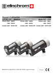
Operating Manual
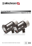
Style RX 300
Version 230V - 20625
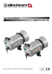
Style RX 600
Version 230V - 20626
120V - 20725
Canada 120V - 20725.1VS
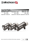
Style RX 1200
Version 230V - 20627
120V - 20726
120V - 20727
Canada 120V - 20726.1VS Canada 120V - 20727.1VS
Elinca S.A Style RX 01.01.2007 ENG (73253) Printed in Switzerland
English
Table of contents
Introduction
2
Declaration of conformity, disposal and recycling, CE marking
3
Safety notice and precaution
4
Operating instructions
5
Control Panel
6
Switch and Fuse
7
Modelling Light
8
Digital power display, Photo-cell
9
Synchronisation, Wireless Remote control and flash triggering
10
Acoustic signal
10
Troubleshooting
7, 10
Flash tube replacement
11
Technical Data
12
Elinchrom Accessories
13
Guarantee
14
P.S: Technical data subject to change.
The listed values are guide values which may vary due to tolerances in components used.
1
Introduction
The Elinchrom Style RX is manufactured by Elinca S.A. CH -1020 Renens/Switzerland
Dear Photographer,
Thank you for buying your Style RX compact flash unit.
All Elinchrom products are manufactured using the most advanced technology. Carefully selected
components are used to ensure the highest quality and the equipment is submitted to many controls
both during and after manufacture. We trust that it will give you many years of reliable service.
All Style RX flash units are manufactured for the studio and location use of professional
photographers. Only by observance of the information given, can you secure your warranty, prevent
possible damage and increase the life of this equipment.
Style 300RX - 600RX - 1200RX
The quality of light and exceptional performance is the result of long research, application of
demanding principles, the long experience of ELINCHROM in lighting products for the studio
and the utilization of the latest technology in this area.
Totally integrated to the range of the ELINCHROM flashes, the Style 300RX - 600RX 1200RX units maintain the traditional look and function that is ELINCHROM.
The control provides continuously variable adjustment of the modelling lamp and the flash
power with precision over 6 f-stop, from full power 1/1 to 1/32 th.
FCC Class B Compliance Statement
Note:
This equipement has been tested and found to comply with the limits for a class B digital device, pursuant to Part
15 of the FCC Rules and meets all requirements of the Canadian Interference-Causing Equipement Regulations.
These limits are designed to provide reasonable protection against harmful interference in a residential
installation. This equipement generates, uses, and can radiate radio frequency energy and, if not installed and
used in accordance with the instruction manual, may cause harmful interference to radio communications.
However, there is no guarantee that interference will not occur in a particular installation. If this equipement
does not cause harmful interferences to radio or television reception, which can be determined by turning the
equipement off and on, the user is encouraged to correct the interferences by one or more of the following
measures:
- Reorient or relocate the receiving antenna.
- Increase the separation between the equipement and receiver.
- Connect the equipement into an outlet on a circuit different from that to which the receiver is connected.
- Consult the dealer or an experienced radio/TV technician for help.
ELINCA S.A. is not responsible for any radio or television interference caused by unauthorised modifications of
this equipement or the substitution or attachment of connecting cables and equipement other than those specified
by ELINCA S.A. The correction of interference caused by such unauthorised modification, substitution or
attachment will be the responsibility of the user.
2
Declaration of conformity
This device complies with Part 15 of the FCC Rules. Operation is subject to the following two
conditions:
1. This device may not cause harmful interference, and
2. This device must accept any interference received, including interference that may cause
undesired operation.
Product name:
Professional Studio Flash unit
Trade name:
ELINCHROM
Model number(s):
Style RX 300/600/1200
Name of responsible party:
Elinca S.A
Av. De Longemalle 11
1020 Renens / Switzerland
Phone :
+41 21 637 2677
Fax:
+41 21 637 2681
We, ELINCA S.A., hereby declare that the equipement bearing the trade name and model number
specified above was tested conforming to the applicable FCC rules, and that all the necessary steps
have been taken and are in force to assure that the production units of the same equipement will
continue to comply with the Comissions requirements.
Disposal and recycling
This device has been manufactured to the highest possible degree from materials which can be recycled or disposed of in a manner that is not enviromentally
damaging. The device may be taken back after use to be recycled, provided that is
returned in a condition that is the result of normal use. Any components not reclaimed will be disposed of in a environmentally acceptable manner.
If you have any question on disposal, please contact your local office or your local ELINCHROM
agent (check our website for a list of all ELINCHROM agents world wide).
CE marking
The shipped version of this device complies with the requirements of ECC directives 89/336/ECC «Electromagnetic compatibility» and 73/23/ECC «Low voltage directive».
Notational Conventions
The meaning of the symbols and fonts used in this manual are as follows:
!
i
Pay particular attention to text marked with this symbol.
Failure to observe this warning endangers your life, destroys the device, or may damage other equipement
Supplementary information, remarks, and tips follow this symbol.
Text which follows this symbol describes activities that must be performed in the order shown.
«Quotation marks» indicate names of chapters or terms
3
Safety notice
According to safety regulations, we draw your attention to the fact that these electronic flash units
are not designed for use outdoors, in damp or dusty conditions and should not be used after being
exposed to sudden temperature changes causing condensation. They must always be connected to
an earthed (grounded) mains supply.
On no account should any object be inserted into the ventilation.
The units may retain an internal charge for a considerable time even though disconnected from the
power supply.
Do not use in restricted area (like hospitals) and in explosive environnements.
Flash Tubes and Modelling lamps
• Flashtubes and modelling lamps in use are very hot!
• Never touch a flash tube or lamp before the unit cooled down and is disconnected from the mains.
• Do not fire flashes from short distance (less than 1m) directed to a person and avoid looking directly into the flashlight!
• Keep distance to flammable materials.
• Keep generally distance to operating units.
Transport
• Transport the flash unit with care and only in its original packaging or another corresponding
packaging fit to protect it against knocks and jolts.
• Transport only in complete discharged conditions. Wait a minimum 30 minutes after removing
from mains supply before packaging and transportation.
• Never drop the flash unit (danger of breaking flash tubes).
Power cable
To guarantee safe operation, use the cable supplied.
• The cable has to be HAR-certified or VDE-certified. the mark HAR or VDE will appear on the outer sheat.
• The cable set must be selected according to the rated current for your flash unit.
• Do not use a spider box to connect one or more flash units.
!
FLASH SYSTEMS STORE ELECTRICAL ENERGY IN CAPACITORS BY
APPLYING HIGH VOLTAGE.
FOR YOUR SAFETY, NEVER OPEN OR DISASSEMBLE YOUR FLASHES.
ONLY AN AUTHORISED SERVICE ENGINEER SHOULD OPEN OR ATTEMPT
TO REPAIR THE UNITS.
INTERNAL DEFECT CHARGE CAPACITORS MAY EXPLODE WHILST THE UNIT IS IN
USE, NEVER SWITCH ON A PROPER WORKING FLASH UNIT.
4
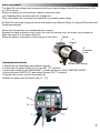
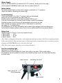
Before you start !
The Style RX unit voltage must correspond with your mains voltage. Style RX are delivered in 120V
or 230V versions.
Before connecting for the first time, check to make sure that
your Modelling lamp coincides with the voltage line.
They must always be connected to an earthed ( grounded) mains supply.
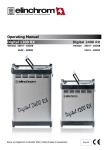
All Style RX units have a bayonet mount and locking ring reflector fitting, for fixing all Elinchrom and
Prolinca accessories.
Mount the unit securely to a suitable stand or support.
Remove the black protective cover (note: first turn the locking ring A as shown, then rotate the
black cap cover B in the same direction).
Fitting a reflector or accessory is the reverse of this action.
handle
A
locking
B
protective
cover
Operating instructions
C
tilthead with locking
1.Check that the modelling lamp voltage is correct.
2.Check that the mains switch (3) is in the OFF ("O" position).
3.Insert mains cable to the MAINS INLET (1) and connect to a FULLY EARTHED OUTLET
4.Using the mains SWITCH (3) and switch the unit ON ("I" position).
5.Connect the synchro cord on the socket (6).
6.Select the power with the touch pad (11 - 12)
12
11
6
1
3
5
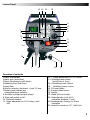
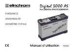
Control Panel
13 14 15
18
9
10
8
6
7
12
11
4
5
22
3
2
20
16
1
21
19
17
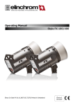
Overview of controls
1.Mains inlet socket
2.Mains fuse (slow blow)
3.Mains Illuminated on/off switch
4.Modelling fuse (fast blow)
5.Open-flash
6.Synchro-sockets, Amphenol + jack 3.5 mm 7.Digital power display and
charge/discharge indicator
8. Acoustic recharging signal (Beep)
9. Slave cell switch on/off
10. Photocell receptor
11. Power adjustment in 1/10 f-stops, with
ADF
12. + Power adjustment in 1/10 f-stops
1 3. Modelling lamp switch
(on/off free or prop)
14.+ Modelling power control
15. - Modelling power control
16. Tilt head clamp
17. Knurled clamp screw
18. Handle
19. Stand 5/8-inch socket
20. Umbrella tube (only for EL
umbrellas, diameter 7 mm)
21.Supplementary locking for others
umbrellas
22. Socket for remote or PC - Multi Link
6
Mains Supply
With the MAINS SWITCH (3) switched off ("O" position), firmly push in the plug
of the original ELINCHROM mains cord into the mains socket (1).
Mains Switch
The switch should light up when the compact is switched on ("I" position).
(Switch off before removing the mains cord).
Troubleshooting
If the on/off switch (3) is ON ("I" position) but not illuminated,
switch off the unit and check the mains fuse (2).
If failed replace with the correct fuse and switch ON the unit.
This unit is protected by a thermal circuit breaker to avoid overheating.
Should this occur, the unit turns off automatically and cannot be fired.
After a break for cooling, the flash will be ready again for operation.
See page 10 / Troubleshooting.
This equipment is not user serviceable and contains high voltages which are dangerous.
In the event of failure, please return the unit to an authorized Elinchrom service station.
Mains Fuse
Standard type 5
• Style 300RX
• Style 600RX
• Style 1200RX
x 20 mm, (use only tempered fuse)
: 5 AT
: 6,3 AT
: 8 AT
Note: Before exchanging a blown fuse, switch off the unit and remove mains cable. Depress and turn the fuse
holder anti-clockwise 1/8th, turn and remove it. If the new fuse blows immediately upon reconnection, return
the unit to an ELINCHROM service centre for a check-up.
(N.B. Please don't forget to check the correct rating of the fuse !).
Fuse for modelling light
Fast type 5 x 20mm, 2.5 AF
Switch off the unit and replace the blown fuse with a new one of the correct rating.
The fastblow fuse will protect the triac of the modelling lamp circuit, the lamp and therefore
the flash tube.
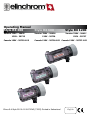
Mains socket
1
Modelling fuse 4 AF
4
Mains fuse 8 AT 2
(Only tempered)
3
Mains switch
7
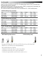
Modelling Light
The touch pad (14) controls the modelling lamp on/off and the proportional light.
Select the power with the touch pad (15). The modelling light output (100%) is achieved when
the power value is set to maximum.
Proportional modelling lamp, is set when the position "PROP" is selected (led is illuminated), the
light output is proportional to the selected flash power.
For all types of Style RX compact flash units, use maximum 250 - 300W modelling lamps.
230V Modelling lamps and fuses
Unit
Modelling lamp
Code
Socket
Fuse
Style 300RX
250W halostar
23018
E27
2,5AF 19033
Code
Style 600RX
250W halostar
23018
E27
2,5AF 19033
Style 1200RX
300W halogen
23022
GX 6,35
2,5AF 19033
120V Modelling lamps and fuses
Unit
Modelling lamp
Code
Socket
Fuse
Code
Style 300RX
150W halogen
23037
BA15D
4 AF
19035
Style 600RX
150W halogen
23037
BA15D
4 AF
19035
Style 1200RX
250W halogen
23038
BA15D
4 AF
19035
120V «Canada Version» Modelling lamps and fuses
Unit
Modelling lamp
Code
Socket
Fuse
Code
Style 300RX
150W halogen
23012
E27
4 AF
19035
Style 600RX
150W halogen
23012
E27
4 AF
19035
Style 1200RX
150W halogen
23012
E27
4 AF
19035
230V Modelling lamp options:
23022
23101
120V Modelling lamp:
23018
23037
This lamp socket adapter E27 to GX 6.35 (code 23101) allows the use of the halogen lamp
300W, GX 6.35 (code 23022) for Style 300 and 600 RX units.
If the modelling lamp does not light up.
1. The filament is broken after long use (replace lamp and fuse)
2. The filament is broken after shock (replace lamp and fuse)
3. An internal component failure (return the unit to customer service)
8
Digital Power Display
The actual flash power is displayed in a f-stop compatible format.
The power range is 6 f-stops. The digital display, provides continuous power indication of the
flash and modelling lamp. The controls cover a continuous output range from full power 1/1 to
1/32th in 1/10th, f-stop intervals.
During charging or discharging, the display "flashes". In case of overheating or malfunction,
the display shows "ER" for error.
Note:
This "Style 300RX, 600RX and 1200RX" units have an integrated discharge system, protected by a
thermic switch.
To avoid overheating, lower power settings, more than 2f-stop, can be discharged manually by releasing
the flash with the «Test» touch button.
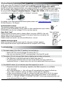
Photocell
The photocell is actived when the green LED (on the touch pad 9) is illuminated.
When switched ON, the unit can be remotely triggered by another flash unit !
The Style BX photocell is specially designed to work under ambiant light conditions in your
studio. Direct light or other strong light sources may reduce the sensitivity of the cell.
In difficult situations e.g. blinding, sunlight or obstacles, the additional cell with 5 m cord
(extensions available) solves most problems.
Additional cell
Extension cord 10 m
: code 11081
: code 11080
Power display
Cell (9)
Photocell
receptor (10)
Modellling
light controls
Test and ready (5)
9
Wireless Remote Control and Flash Triggering
All RX units, Style RX, Digital RX, Ranger RX are equipped with the Remote Plug, to connect the
EL-Skyport Trigger and Remote System. With the EL- Skyport RX Trigger Set 19362,
the RX units can be triggered wireless, up to approximately 100 m distance. Apart from triggering,
the Transmitter offers modelling lamp on /off settings and flash power control in 1/10th steps.
By using the EL- Skyport Computer Remote / Trigger Set 19361, all RX functions can be
controlled and operated with a MAC° or Windows° computer.
19361
19362
For details of the most advanced wireless system please visit www.elinchrom.com > Products >
RX Multi Remote > EL-Skyport.
Sync
Sychronisation socket
6
The standard socket 3.5 mm mini-jack (6).
N.B. Do not link ELINCHROM units by cable to other manufacturers sync outlets.
ELINCHROM uses the low voltage (5 V) for security reasons.
Open flash "test"
Test and Ready
Having pressed the touch pad to release a flash, the green «READY» light will
5
appear again once the unit is recharged. If the green light does not appear the
charge system could be defective.
Please contact and send to an authorized Elinchrom service.
Beep
8
Audible recharge signal
Select the function with the touch pad (8), the green indicator appears.
Once recycled an acoustic signal indicates that the compact unit is ready.
Troubleshooting
1. The mains switch (3) is ON ("I" position), but not light up:
• Switch OFF the unit and change the mains fuse (2)
• Use only time-lag fuse (16 AT), corresponding to the Style RX model
2. The switch (3) is lit, the open flash ready is lighting up but does not function.
• The flashtube in the flashhead may be faulty (see page 11)
• If replacing the flashtube does not solve the problem, the cause could be a
component failure => please return the unit to an authorised Elinchrom service.
3. The ON/OFF switch (3) is lit but the open flash signal (6) is not lit
• Temporary break for overheating, caused by fast flash sequences or ventilation
slots obturated
• Fan cooling defective => the unit turns off automatically and cannot be fired any
more. After a break for cooling, the flash is ready again for operation.
• If after several minutes of break for cooling the ready signal (6) is not lit, the cause
could be a component failure. However, high voltage may remain on the capacitor
circuits. => DO NOT ATTEMPT TO REPAIR THE UNIT. In this case please send the unit
to an authorised Elincrom station.
10
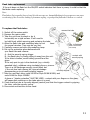
Flash tube replacement
If the unit does not flash but the ON/OFF switch indicates that there is power, it could be that the
flashtube needs replacing.
Note:
Flash tubes (Swiss quality) have a long life with average use, but multiflashing in long sequences can cause
overheating of the electrodes leading to premature ageing, or perhaps the flash tube is broken or cracked.
To replace the Flash tube:
remove the tube
1. Switch off the mains switch
2. Remove the mains cable
3. Take the unit from its stand or lay it
horizontally on a rigid surface. It will need to
be held firmly whilst removing and replacing the tube.
4. Allow the flash tube and modelling lamp to cool
Stand
Plug- in flashtube
for several minutes. They may be very hot.
(made in Switzerland)
5. Carefully remove and store the modelling lamp.
(code 24029)
6. Put on the protective glove delivered with
your flash tube and remove:
A - first the security spring trigger
contact with
B - the flash tube, by firmly pulling it away from the unit.
security spring
If the tube is broken, avoid cutting yourself and the
glove.
If the only part to grip is the electrode (e.g. a totally
smashed tube), withdraw using insulated pliers or pincers.
There is a full discharge security circuit fitted, but
if the unit has had a heavy fall, internal damage
correctly aligned
disconnecting a circuit could possibly happen.
7. Take the new flash tube, code 24029 for Style 300BX-600RX, and
code 24068 for Style 1200RX.
A glove or "plastic protection" MUST BE USED - contact with your fingers on the glass,
will cause dark markings on the tube when it is used.
8. Check that the tube is correctly aligned (central) and that the trigger contact is gripping
the tube, refix the security spring.
9. Re-connect and test the unit as usual.
11
Features
• Locking bayonet ring for accessory and reflector fitting
• Tilthead whit 5/8" - inch stand socket
• Thermal safety
• User replaceable flash tube UV coated (5650°K)
• Halogen modelling lamp 250W, with E27 fitting, and
300W/GX6.35for Style 1200RX (230V Version)
• Silent fan cooling
• Controls for: modelling on/off, cell on/off, acoustic signal on/off.
• Flash and modelling power control.
• «X» synchro jack socket 3,5 mm.
• Socket for Plug-In remote control.
• Auto dumping function. Automatic discharge of flash power
• Central umbrella tube plus external fitting
• Acoustic recharging signal
• Mains cable
• Synchro cord of 5m (jack 3.5mm plug)
• Protective cover
• Total compatibility with all Elinchrom accessories
• Very fast recycling time
• Very short flash duration
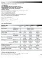
Technical data
Flash power
300RX
J(Ws)
Power supply
600RX
300
1200RX
600
230V Version
V
all units 215-240
120V Version
V
all units 110-120
F-stop, 1m, 100 ISO, with reflector 48°
Control range
GN
64,1
90,1
1200
128,1
J(Ws)
9-300
18-600
36-1200
230V Version
s
0,2-0,6
0,25-0,8
0,35-1,5
120V Version
s
0,25-1
0,3-1,6
0,35-2,8
s
1/2850
1/2050
1/1450
s
1/1350
1/850
1/480
230V Version
W
250*/E27
250*/E27
300 GX 6,35
120V Version
W
150/BA15D
150/BA15D
250/BA15D
120V «Canada Version»
W
150/E27
150/E27
150/E27
V
5
5
5
(W)
5/1150
6,3/1500
8/1840
Recycling time
Flash duration (t 0,5) 1/1
(t 0,5) 1/32
Modelling lamp
Voltage across sync cable
Connected load A/VA
Radio interference suppressiv CE-IEC 491 EN 60 555 - EN 61 000 - 4 - 2/3/4/5
Dimension length x diam.
cm
21x14
21x14
30x14
Weight
kg
2,15
2,45
3,45
* Optional alternative 300W/GX6.35
Tolerances and specifications conforming to IEC and CE standards.
Technical data subject to change without notice.
12
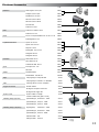
Elinchrom Accessories
code
Reflectors
Wide angle ø 16 cm /90°
Compact ø 18 cm /60°
Standard ø 21 cm /50°
26144
Mini Soft ø 44 cm silver
Grids
Filters
Lightbanks ROTALUX
26143
26141
26168
Snoot & Grid
26061
Grid set for snoot
26427
Grid set for reflector 18 cm
26135
Grid set for 21 cm 26051
Set of 10 color/mixed filters for 21 cm x 21 cm
26243
Polarizing filter 21 cm 26244
Square 70 x70 cm
26178
Square 100 x100 cm
Strip 95 x 35 cm
26179
26180
Rectangular 130 x 50 cm
Octagonal 100 cm
Umbrellas
Octagonal 135 cm
26184
White diam. 85 cm 26372
Silver diam. 85 cm Stands
26181
26183
26350
Translucent diam. 85 cm
Spots
26166
Mini Soft ø 44 cm white
Zoom Spot 18° - 36°
26371
26481
Mini Spot
26420
Stand 85-235cm
30101
Stand Master 109-385 cm
30149B
Bags
Carrying bag for 2 Style RX 600
33197
Carrying bag for 2 stands + 2 umbrellas
33220
Case
Carrying case for 3 mono compatcs
33209
Trigger accessories
IR flash remote
40203
EL-Skyport computer remote Set
19361
EL-Skyport RX Trigger Set
19362
Synchro cords
Synchro cable 5 m length
camera to flash units (jack 3.5 mm)
11084
Modelling lamps (90/140V)
Quartz Halogen, Socket E27 - 150W
23019
Quartz Halogen, GX 6,35 - 150W
23031
Modelling lamps (190/260V)
Quartz Halogen, GX 6.35 - 200W
23033
Kypton/photo,
Socket E27 - 100W
23002
Quartz Halogen, Socket E27 - 150W
23035
Quartz Halogen, GX 6.35 - 200W
23034
Halostar 250W - E27
23018
Halogen 300W - GX 6.35
23022
13
Guarantee
This ELINCHROM product will be repaired free of charge by the vending agent if during a period of
24 months from date of purchase its working order is impaired through a manufacturing or material
defect. The faulty product should be immediately sent to the authorized dealer or ELINCA agent.
This guarantee is not valid for equipment which has been misused, dismantled, modified or repaired
by persons not belonging to the ELINCA distribution network. It does not cover flash tubes, lamps
and the normal ageing of capacitors. No responsibilities can be accepted for damage resulting from
unsatisfactoıy operation of the equipment, such as wasted film or other expenses.
i
Please „register“ your Elinchrom product online, under
www.elinchrom.com > Downloads > Product Registration
In case you cannot register your Elinchrom unit via internet, please fill in the
Guarantee card and post it to Elinca.
Please return this registratioin card directly to
Diese Registrierkarte bitte direkt zurücksenden an
Veuillez retourner cette carte d’enregistrement directement à
Vi preghiamo di far pervenire questa cartolina di iscrizione direttamente a
Por favor envie esta carta de registro directamente
Elinchrom model
Elinchrom modèle
Elinchrom modell
Modello di Elinchrom
Modelo de Elinchrom
:
:
:
:
:
Date of purchase
Datum des Kaufs
La date d’achat
La data di acquisto
La fecha de la compra
:
:
:
:
:
Your full name and address
Ihr voller Name und redet an
Votre nom complet et adresse
Il suo nome pieno ed indirizza
Su nombre y apellidos y dirige
:
:
:
:
:
:
:
:
:
:
elinca sa
P.O. Box 458
Avenue de Longemalle 11
CH-1020 Renens
Switzerland
N°
Dealer
Händler
Négociant
Il distributore
El comerciante
:
:
:
:
:
14
www.elinchrom.com