1
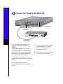
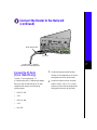
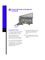
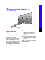
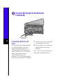
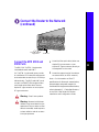
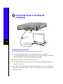
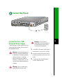
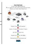
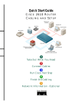
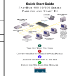
Cisco 7100 SERIES
1
PREPARE FOR INSTALLATION
2
RACK-MOUNT THE ROUTER
3
CONNECT THE ROUTER TO THE NETWORK
4
CONNECT THE POWER
5
START THE SYSTEM
18481
CISCO
Quick Start Guide
7100 S E R I E S VPN R O U T E R
Prepare for Installation
Note: For detailed hardware installation instructions and safety guidelines, refer to the
Cisco 7100 Series VPN Router Installation and Configuration Guide.
Warning Only trained and qualified personnel should install, replace, or service this
equipment.
Warning Read the Installation instructions before you connect the system to its
power source.
Warning This unit is intended for installation in restricted access areas. A restricted
access area is where access can only be gained by service personnel through the use of
a special tool, lock and key, or other means of security, and is controlled by the
authority responsible for the location.
1
Ensure the site is set up properly and ensure your safety when installing the router:
— Lift the router safely out of the packing container.
— Ensure the power service at the site is suitable for the router you are installing.
2
Check the packing slip to ensure that all the proper components are present.
3
Verify that you have the required tools and parts:
— 19- and 24-inch rack-mount brackets.
— Four screws for installing the router in the rack (not included).
— One double ground lug and two Phillips-head machine screws with locking washers.
— Number 2 Phillips screwdriver (not included).
— Appropriate cables to connect the router to the network and console terminal.
— Power cord (two power cords if dual power supply).
— ESD-preventive wrist strap.
1
Prepare for Installation (continued)
— One grounding wire—6-AWG, 0.162-inch (4.115-mm) diameter, with approximately
0.108 inch (2.743 mm) of insulation, for a total wire diameter of approximately
0.27 inch (6.858 mm). The wire’s length is dependent on your router location and site
environment. This wire is not available from Cisco Systems; it is available from any
commercial cable vendor.
— Crimping tool large enough to accommodate the diameter of the wire receptacle on
your grounding lug.
— Wire stripper.
2
22061
Rack-Mount the Router
22062
Cisco 7100 SERIES
0
3
2
Attach the Brackets to the
Router
1
Locate the brackets and screws.
2
Use a Phillips screwdriver to attach the
brackets on the side panels of the router
in one of the following ways:
— Front panel forward
— Rear panel forward
Note: Although these installations show
the 19-inch brackets, the procedure is the
same for the larger brackets.
Note: This procedure assumes you are
installing the router in a rack. For tabletop
installation, refer to the Cisco 7100 Series
VPN Router Installation and Configuration
Guide.
.
22064
Rack-Mount the Router (continued)
0
2
Note: The second bracket attaches to the other side of the chassis.
The brackets can also be installed with the front panel forward.
4
Attach the Router to the Rack
1
Locate the screws to mount the chassis
in the rack.
2
Position one person to lift the chassis
into the equipment rack.
3
Align the bracket holes with the
mounting holes in the equipment rack.
4
Use a Phillips screwdriver to attach the
router to the equipment rack.
Warning Do not touch the power
supply when the power cord is
connected. For systems with a
power switch, line voltages are
present within the power supply
even when the power switch is off
and the power cord is connected.
For systems without a power
switch, line voltages are present
within the power supply when the
power cord is connected.
Rack-Mount the Router (continued)
22065
Chassis grounding receptaces
Screws
Grounding lug
0
2
Grounding wire
Attach the Grounding Lug
5
Note: Before you connect power or power
on your router, we strongly recommend that
you attach the grounding lug to the chassis
grounding receptacles.
Insert the two screws through the holes
in the grounding lug. Ensure that the
grounding lug does not interfere with
other router hardware.
6
Use a Phillips screwdriver to carefully
tighten the screws until the grounding
lug is held firmly to the chassis. Do not
overtighten the screws.
7
Connect the opposite end of the
grounding wire to the appropriate
grounding point at your site to ensure
an adequate chassis ground.
1
Locate the grounding lug and screws.
2
Use the wire stripper to strip one end of
the 6-AWG wire approximately
0.75 inch (19.05 mm).
3
Insert the 6-AWG wire into the wire
receptacle on the grounding lug.
4
Use the crimping tool to carefully crimp
the wire receptacle around the wire; this
step is required to ensure a proper
mechanical connection.
5
22068
Connect the Router to the Network
AC OK
DC OK
OTF
SLOT 0
5
SLOT 1
ACT ACT
PWR
I
E3
EN
RX
TX
RX
FE 0 / 0
FE 0 / 1
E3
CEL CAR ALM
EN
RX
0
LNK LNK
0
1
TX
CONS
RX
AUX
SYS
RDY
AC OK
DC OK
OTF
CEL CAR ALM
2
7140 - 2AE3
100-240Vac 50/60Hz
5-2.5A 525W
10BaseT/100BaseTX ports
Fast Ethernet 0/0
(RJ-45)
8
6
7
6
Cisco 7100 series router
Ethernet hub
5
4
3
2
1
Crossover
Ethernet cable
Connect the Fast Ethernet
Ports
The 10BaseT/100BaseTX Fast Ethernet
ports support IEEE 802.3 and IEEE 802.3u
specifications for 10-Mbps and 100-Mbps
transmission over unshielded twisted-pair
(UTP) cables. These ports support
autosensing and autonegotiation of the
proper transmission mode with an attached
device.
Note: Unless noted otherwise, all
procedures apply to any Cisco 7100 series
router.
1
Attach a standard straight-through or
crossover Category 3 or Category 5
UTP cable directly to the RJ-45
receptacle on the router.
2
Attach the network end of the cable to
an Ethernet hub or end station.
Connect the Router to the Network
(continued)
5
Strain-relief screws
EN
TD
TC
RD
RC
LB
CD
TD
TC
RD
RC
LB
CD
TD
TC
RD
RC
LB
CD
TD
TC
RD
RC
LB
CD
22070
I
Serial 1/0
7
To CSU, DSU, or external
synchronous serial equipment
Connect the T1 Ports
(Cisco 7120-4T1 only)
The four T1 ports operate at T1
(1.544-Mbps) and E1 (2.048-Mbps) speeds
Each port uses an identical 60-pin D-shell
receptacle that supports the following
interface types:
•
EIA/TIA-232
•
V.35
•
EIA/TIA-449
•
X.21
•
EIA-530
1
Attach the appropriate serial cable
directly to the receptacle on the router
and tighten the strain-relief screws.
2
Attach the network end of the serial
cable to a DSU, CSU, DTE, or other
external synchronous serial equipment
and tighten the strain-relief screws.
Connect the Router to the Network
(continued)
5
RCVR
EN
XMTR
RCLK FERF RL RCLK FERF
RL
RCVR
XMTR
22072
I
AIS OOF LL AIS OOF LL
Serial 1/0
Serial 2/0
To T3 network
equipment
8
Connect the T3 Ports
1
The T3 port supports full-duplex operation
at T3 (45-Mbps) speeds. Use a 75-ohm
coaxial cable to connect to a T3 serial
network. Serial cables conform to
EIA/TIA-612 and EIA/TIA-613
specifications. The T3 serial ports on the
router are considered to be DTE devices.
Attach the appropriate 75-ohm coaxial
cable directly to the receptacle on the
router and tighten the strain-relief
screws.
2
Attach the network end of the coaxial
cable to the external synchronous serial
equipment.
Note: The T3 ports support several types
of integrated DSUs. For a listing of DSU
feature compatibilities, refer to Appendix C,
“Cable Specifications,” in the Cisco 7100
Series VPN Router Installation and
Configuration Guide.
Connect the Router to the Network
(continued)
5
RCVR
EN
XMTR
RCLK FERF RL
AIS OOF LL
22073
I
Serial 1/0
Ferrite bead
To E3 network
equipment
9
Connect the E3 Ports
1
The E3 port supports full-duplex operation
at E3 (34-Mbps) speeds. Use a 75-ohm
coaxial cable to connect to an E3 serial
network. Serial cables conform to
EIA/TIA-612 and EIA/TIA-613
specifications. The E3 serial ports on the
router are considered to be DTE devices.
Attach the appropriate 75-ohm coaxial
cable directly to the receptacle on the
router and tighten the strain-relief
screws.
2
Attach the network end of the coaxial
cable to the external synchronous serial
equipment.
Note: The E3 ports support several types
of integrated DSUs. For a listing of DSU
feature compatibilities, refer to Appendix C,
“Cable Specifications,” in the Cisco 7100
Series VPN Router Installation and
Configuration Guide.
Note: The E3 coaxial cable comes with an
attached ferrite bead.
Connect the Router to the Network
(continued)
5
DS3
EN
RX
TX
RX
22127
I
CEL CAR ALM
Serial 1/0
To ATM T3 network
equipment
10
Connect the ATM T3 or E3
Ports
1
Attach a 75-ohm coaxial cable directly
to the receptacle on the router.
The T3 port supports full-duplex operation
at T3 (45-Mbps) speeds. The E3 port
supports full-duplex operation at E3
(34-Mbps) speeds. Use a 75-ohm coaxial
cable to connect to a T3 or E3 ATM serial
network. Serial cables conform to
EIA/TIA-612 and EIA/TIA-613
specifications. The T3 and E3 serial ports on
the router are considered to be DTE devices.
2
Attach the network end of the cable to
the external synchronous serial
equipment.
Note: The E3 coaxial cable (not shown)
comes with an attached ferrite bead.
Connect the Router to the Network
(continued)
5
EN
RX 155 - MM TX
RX
22129
I
CEL CAR ALM
To ATM network
equipment
ATM 1/0
Connect the ATM SMI3 and
MM3 Ports
The SMI3 (OC-3c/STM-1 single-mode
intermediate reach) and MM3
(OC-3c/STM-1 multimode) ports provide
an interface to ATM networks and transmit
and receive data at rates of up to 155 Mbps
bidirectionally. The SMI3 and MM3 ports
connect to a SONET/SDH single-mode or
multimode optical fiber cable. Use one
duplex SC-type connector or two simplex
SC-type connectors.
Warning Class 1 laser product.
Warning Because invisible laser
radiation may be emitted from the
aperature of the port when no fiber
cable is connected, avoid exposure
to laser radiation and do not stare
into open apertures.
1
2
Attach the fiber-optic cable (either one
duplex SC-type connector or two
simplex SC-type connectors) directly to
the receptacle on the router.
Attach the network end of the cable to
an external DSU (an ATM network).
Note: For information on SONET
specifications for fiber-optic transmissions,
power budget, and power margins for
multimode and single-mode transmissions,
refer to Appendix C, “Cable Specifications,”
in the Cisco 7100 Series VPN Router
Installation and Configuration Guide.
11
22069
Connect the Router to the Network
(continued)
AC OK
DC OK
OTF
SLOT 0
5
SLOT 1
ACT ACT
PWR
I
E3
EN
RX
TX
RX
FE 0 / 1 0
E3
CEL CAR ALM
EN
0
LNK LNK
1
FE 0 / 0
RX
TX
CONS
RX
AUX
SYS
RDY
AC OK
DC OK
OTF
CEL CAR ALM
2
7140 - 2AE3
100-240Vac 50/60Hz
5-2.5A 525W
Cisco 7100 series router
Console port
(RJ-45)
PC (laptop)
RJ-45-to-RJ-45
rollover cable
12
RJ-45-to-DB-9 or
RJ-45-to-DB-25 adapter
(labeled TERMINAL)
Connect the Console Port
Use the console terminal for local administrative access to the router.
1
Attach the appropriate cable (RJ-45 rollover cable and an RJ-45-to-DB-25 or
RJ-45-to-DB-9 adapter) directly to the receptacle on the router. The adapters provided are
labeled TERMINAL. Other types of adapters are not included.
2
Attach the other end of the cable to a terminal or PC.
3
Configure the terminal or PC terminal emulation software for 9600 baud, 8 data bits, no
parity, and 2 stop bits.
Note: Refer to the “Connecting the Console Port and Auxiliary Port” section in Chapter 3,
“Installing Cisco 7100 Series Routers,” in the Cisco 7100 Series VPN Router Installation and
Configuration Guide.
22131
Connect the Power
SLOT 0
5
SLOT 1
ACT ACT
PWR
I
RCVR
EN
XMTR
RCLK FERF RL
FE 0 / 0
FE 0 / 1
0
LNK
1
CONS
AUX
SYS
RDY
AIS OOF LL
2
7120 - T3
Warning The plug-socket
Connect the Cisco 7120
Series AC Power Supply
The power supply is a four-output switching
power supply with power factor correction
and regulated outputs.
combination must be accessible at
all times because it serves as the
main disconnecting device.
1
At the rear of the router, check that the
power switch is in the off (O) position.
2
Connect one end of the power cord to
the power connector on the rear of the
router.
3
Connect the other end of the power
cord to the power outlet.
Warning Never defeat the ground
conductor or operate the equipment
in the absence of a suitably installed
ground conductor. Contact the
appropriate electrical inspection
authority or an electrician if you are
uncertain that suitable grounding is
available.
Warning The AC power supply
has double pole/neutral fusing.
13
22135
Connect the Power (continued)
AC OK
DC OK
OTF
SLOT 0
5
SLOT 1
ACT ACT
PWR
I
E3
EN
RX
TX
RX
FE 0 / 0
FE 0 / 1
E3
CEL CAR ALM
EN
RX
0
LNK LNK
0
1
TX
RX
CONS
AUX
SYS
RDY
AC OK
DC OK
OTF
CEL CAR ALM
2
7140 - 2AE3
AC power cable
100-240Vac 50/60Hz
5-2.5A 525W
Cable-retention clip
14
Connect the Cisco 7140 Series Dual AC Power Supply
The power supply is a four-output switching power supply with power factor correction and
regulated outputs.
Note: For additional AC power cable strain relief, secure the cable to the power supply handle
by inserting a nylon cable tie through the hole in the handle and around the cable.
1
At the rear of the router, check that the power switch is in the off (O) position.
2
Slide the cable-retention clip up, away from the AC receptacle, and plug in the power cable.
3
Secure the cable in the power supply AC receptacle by sliding the cable-retention clip down
until it fits around the connector. The cable-retention clip provides strain relief for the AC
power cable.
4
Plug the AC power supply cable into the AC power source.
Note: For full redundancy, plug the second AC power cord into a separate power source.
Start the System
Check Conditions Prior to System Startup
Check the following conditions before you start your router:
•
Any port adapter or service module is securely inserted in its slot.
•
All network interface cables are connected.
•
A Flash Disk or Flash memory card is installed in its PC Card slot.
•
The power cable is connected (for dual power supplies, the cable-retention clip is secured).
•
The console terminal is connected and powered on.
Start the System
1
At the rear of the router, place the power switch on the power supply in the on (|) position.
The green power LED on the router goes on.
2
Listen for the fans; you should immediately hear them operating.
3
During the boot process, observe the system LEDs. The LEDs on most of the fixed
interfaces and port adapters go on and off in irregular sequence.
4
Observe the initialization process. When the system boot is complete (a few seconds), the
network processor begins to initialize the interfaces. During this initialization, the LEDs on
each port behave differently (most flash on and off). When initialization is complete, the
enabled LED on each interface goes on.
Note: For more information on LEDs, refer to the “System LEDs and Reset Button” section
in Chapter 1, “Cisco 7100 Series Product Overview,” in the Cisco 7100 Series VPN Router
Installation and Configuration Guide.
15
Start the System (continued)
Use the Setup Facility
This section provides a sample of a basic router configuration using the setup facility. The
output from the setup facility varies depending on the Cisco 7100 series model you are
installing. It does not contain a complete example of all possible features that can be used by
the various interfaces.
Note: For information the defaults settings for the various interfaces, and procedures on how
to use autoinstall or global configuration mode to configure the router, refer to Chapter 4,
“Performing a Basic Startup Configuration,” in the Cisco 7100 Series VPN Router Installation
and Configuration Guide.
1
16
Power on the router. After startup, the console screen displays a script and a system banner
similar to the following. When you see this information, you have successfully booted your
router.
Restricted Rights Legend
Use, duplication, or disclosure by the Government is
subject to restrictions as set forth in subparagraph
(c) of the Commercial Computer Software - Restricted
Rights clause at FAR sec. 52.227-19 and subparagraph
(c) (1) (ii) of the Rights in Technical Data and Computer
Software clause at DFARS sec. 252.227-7013.
cisco Systems, Inc.
170 West Tasman Drive
San Jose, California 95134-1706
Cisco Internetwork Operating System Software
IOS (tm) EGR Software (c7100-P-M), Release Version 12.0(19990204:220751)
[biff-bigrock.sync 122]
Copyright (c) 1986-1999 by cisco Systems, Inc.
Compiled Mon 08-Feb-99 11:26 by biff
Image text-base:0x60008900, data-base:0x609D2000
cisco 7140 (EGR) processor with 90112K/73728K bytes of memory.
R7000 CPU at 262Mhz, Implementation 39, Rev 1.0, 256KB L2, 2048KB L3 Cache
4 slot midplane, Version 0.1
Start the System (continued)
Last reset from power-on
X.25 software, Version 3.0.0.
2 FastEthernet/IEEE 802.3 interface(s)
2 ATM network interface(s)
125K bytes of non-volatile configuration memory.
8192K bytes of Flash PCMCIA card at slot 1 (Sector size 128K).
8192K bytes of Flash internal SIMM (Sector size 256K).
2
Enter yes or press Return to enter the initial configuration dialog:
--- System Configuration Dialog --Would you like to enter the initial configuration dialog? [yes/no]: yes
At any point you may enter a question mark '?' for help.
Use ctrl-c to abort configuration dialog at any prompt.
Default settings are in square brackets '[]'.
Basic management setup configures only enough connectivity
for management of the system, extended setup will ask you
to configure each interface on the system
3
17
Enter yes or press Return to see the current interface summary:
First, would you like to see the current interface summary? [yes]: yes
Any interface listed with OK? value “NO” does not have a valid configuration
Interface
FastEthernet0/0
FastEthernet0/1
ATM1/0
ATM2/0
IP-Address
unassigned
unassigned
unassigned
unassigned
OK?
NO
NO
NO
NO
Method
unset
unset
unset
unset
Status
up
up
down
down
Protocol
up
up
down
down
Note: The example shows a router at first-time startup; that is, nothing is configured. The type
of interfaces vary depending on the type of Cisco 7100 series router you are using and the type
of modular port adapter installed in the router.
Start the System (continued)
4
Enter router host name, the enable secret password, enable password, and the virtual
terminal password:
Configuring global parameters:
Enter host name [Router]: sanjose
The enable secret is a password used to protect access to
privileged EXEC and configuration modes. This password, after
entered, becomes encrypted in the configuration.
Enter enable secret: barney
The enable password is used when you do not specify an
enable secret password, with some older software versions, and
some boot images.
Enter enable password: betty
The virtual terminal password is used to protect
access to the router over a network interface.
Enter virtual terminal password: fred
18
5
Enter yes or press Return to accept SNMP management; enter no to refuse it:
Configure System Management? [yes/no]: no
Configure SNMP Network Management? [yes]: no
Note: The Simple Network Management Protocol (SNMP) is the most widely supported open
standard for network management. It provides a means to access and set configuration and
run-time parameters of routers and communication servers. SNMP defines a set of functions
that can be used to monitor and control network elements.
6
Enter yes or press Return to configure IP routing and select an interior routing protocol:
Configure IP? [yes]: yes
Configure IGRP routing? [yes]: yes
Your IGRP autonomous system number [1]: 15
Configure CLNS? [no]: no
Note: Choose which protocols to support on your interfaces. For IP-only installations, you
can accept the default values for most of the questions. In most cases, you use IP routing. If
you are using IP routing, you must also select an interior routing protocol. You can specify only
one of two interior routing protocols to operate on your system using setup: Interior Gateway
Routing Protocol (IGRP) or Routing Information Protocol (RIP).
Start the System (continued)
7
Configure the Fast Ethernet LAN port in slot 0. Use your own addresses and subnet mask
at the setup prompts. Consult with your network administrator for this information.
Configuring interface parameters:
Do you want to configure FastEthernet0/0 interface? [yes]: yes
Use the 100 Base-TX (RJ-45) connector? [yes]: yes
Operate in full-duplex mode? [no]: yes
Configure IP on this interface? [yes]: yes
IP address for this interface: 10.0.0.0
Subnet mask for this interface [255.0.0.0]:
Class A network is 10.0.0.0, 8 subnet bits; mask is /8
Do you want to configure FastEthernet0/1 interface? [yes]: no
Note: Many of the interface LEDs do not go on until you have configured them. To verify
correct operation of each interface, complete the first-time startup procedures and
configuration, and then refer to the LED descriptions in Chaper 1, “Cisco 7100 Series VPN
Router Product Overview” in the Cisco 7100 Series VPN Router Installation and
Configuration Guide to check the status of the interfaces.
8
Configure the ATM port in slot 1. Use your own addresses and subnet mask at the setup
prompts. Consult with your network administrator for this information.
Do you want to configure ATM1/0 interface? [yes]: yes
Configure IP on this interface? [yes]: yes
IP address for this interface: 10.0.0.10
Subnet mask for this interface [255.0.0.0]:
Class A network is 10.0.0.10, 8 subnet bits; mask is /8
Do you want to configure ATM2/0 interface? [yes]:no
9
Configure the synchronous serial port in slot 4. Use your own addresses and subnet mask
at the setup prompts. Consult with your network administrator for this information.
Do you want to configure Serial4/0 interface 3/0 [yes]: yes
Configure IP on this interface? [yes]: yes
IP address for this interface: 10.1.1.20
Number of bits in subnet field [0]:
Class A network is 10.1.1.0, 0 subnet bits; mask is /24
19
Start the System (continued)
10
Review your configuration.
The following configuration command script was created:
20
hostname sanjose
enable secret 5 $1$gG.I$gc9JUfK2r6pIDL0vo3j191
enable password betty
line vty 0 4
password fred
no snmp-server
!
ip routing
no clns routing
!
interface FastEthernet0/0
media-type 100BaseX
full-duplex
ip address 10.1.1.20 255.0.0.0
!
interface FastEthernet0/1
shutdown
no ip address
!
interface ATM1/0
ip address 10.1.1.10 255.0.0.0
!
interface ATM2/0
shutdown
no ip address
!
router igrp 15
redistribute connected
network 1.0.0.0
!
end
Start the System (continued)
11
Save your settings to NVRAM by selecting option 2.
[0] Go to the IOS command prompt without saving this config.
[1] Return back to the setup without saving this config.
[2] Save this configuration to nvram and exit.
Enter your selection [2]: 2
Your router is now minimally configured and ready to use. You can use the setup command if
you want to modify the parameters after the initial configuration. To perform more complex
configurations, use the configure command.
Note: If the system does not complete each of the steps in the startup procedure, proceed to
Chapter 5, “Troubleshooting the Installation,” in the Cisco 7100 Series VPN Router
Installation and Configuration Guide for troubleshooting recommendations and procedures.
For More Information
For information on additional interface configuration and specific system configurations, see
the following publications:
•
Cisco 7100 Series VPN Configuration Guide that shipped with your router. This document
contains sample configurations.
•
Cisco 7100 Series VPN Router Installation and Configuration Guide. This document
contains detailed information on hardware installation, software setup, and
troubleshooting guidelines.
•
Modular configuration and modular command reference publications in the Cisco IOS
software configuration documentation set that corresponds to the software release installed
on your Cisco hardware.
21
Corporate Headquarters
Cisco Systems, Inc.
170 West Tasman Drive
San Jose, CA 95134-1706
USA
http://www.cisco.com
Tel: 408 526-4000
800 553-NETS (6387)
Fax: 408 526-4100
European Headquarters
Cisco Systems Europe s.a.r.l.
Parc Evolic, Batiment L1/L2
16 Avenue du Quebec
Villebon, BP 706
91961 Courtaboeuf Cedex
France
http://www-europe.cisco.com
Tel: 33 1 69 18 61 00
Fax: 33 1 69 28 83 26
Americas
Headquarters
Cisco Systems, Inc.
170 West Tasman Drive
San Jose, CA 95134-1706
USA
http://www.cisco.com
Tel: 408 526-7660
Fax: 408 527-0883
Asia Headquarters
Nihon Cisco Systems K.K.
Fuji Building, 9th Floor
3-2-3 Marunouchi
Chiyoda-ku, Tokyo 100
Japan
http://www.cisco.com
Tel: 81 3 5219 6250
Fax: 81 3 5219 6001
Cisco Systems has more than 200 offices in the following countries. Addresses, phone numbers, and fax numbers are listed on the
C i s c o C o n n e c t i o n O n l i n e We b s i t e a t h t t p : / / w w w. c i s c o . c o m / o f fi c e s .
Argentina • Australia • Austria • Belgium • Brazil • Canada • Chile • China • Colombia • Costa Rica • Croatia • Czech Republic • Denmark • Dubai, UAE
Finland • France • Germany • Greece • Hong Kong • Hungary • India • Indonesia • Ireland • Israel • Italy • Japan • Korea • Luxembourg • Malaysia
Mexico • The Netherlands • New Zealand • Norway • Peru • Philippines • Poland • Portugal • Puerto Rico • Romania • Russia • Saudi Arabia • Singapore
Slovakia • Slovenia • South Africa • Spain • Sweden • Switzerland • Taiwan • Thailand • Turkey • Ukraine • United Kingdom • United States •
Venezuela
Access Registrar, AccessPath, Any to Any, AtmDirector, CCDA, CCDE, CCDP, CCIE, CCNA, CCNP, CCSI, CD-PAC, the Cisco logo, Cisco Certified Internetwork Expert logo, CiscoLink, the Cisco
Management Connection logo, the Cisco NetWorks logo, the Cisco Powered Network logo, Cisco Systems Capital, the Cisco Systems Capital logo, Cisco Systems Networking Academy, the Cisco
Technologies logo, ControlStream, Fast Step, FireRunner, GigaStack, IGX, JumpStart, Kernel Proxy, MGX, Natural Network Viewer, NetSonar, Network Registrar, Packet, PIX, Point and Click
Internetworking, Policy Builder, Precept, RouteStream, Secure Script, ServiceWay, SlideCast, SMARTnet, StreamView, The Cell, TrafficDirector, TransPath, ViewRunner, VirtualStream, VisionWay,
VlanDirector, Workgroup Director, and Workgroup Stack are trademarks; Changing the Way We Work, Live, Play, and Learn, Empowering the Internet Generation, The Internet Economy, and The
New Internet Economy are service marks; and Asist, BPX, Catalyst, Cisco, Cisco IOS, the Cisco IOS logo, Cisco Systems, the Cisco Systems logo, the Cisco Systems Cisco Press logo, Enterprise/Solver,
EtherChannel, EtherSwitch, FastHub, FastLink, FastPAD, FastSwitch, IOS, IP/TV, IPX, LightStream, LightSwitch, MICA, NetRanger, Registrar, StrataView Plus, Stratm, TeleRouter, and VCO are
registered trademarks of Cisco Systems, Inc. in the U.S. and certain other countries. All other trademarks mentioned in this document are the property of their respective owners. (9904R)
Printed in the USA on recycled paper containing 10% postconsumer waste.
78-6343-01