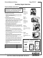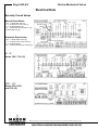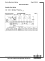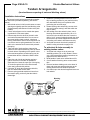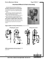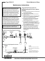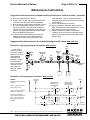
1
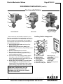
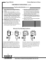
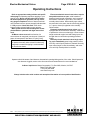
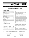
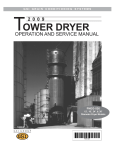
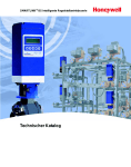
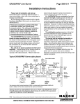
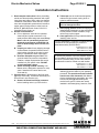
Electro-Mechanical Valves
Page 6100-S-1
Installation Instructions
1. Read complete instructions before proceeding
and do not discard packing materials until any/all
loose items are located. Also, make sure that the
installation of the Maxon valves will be in compliance with all applicable governmental, insurance
and/or agency requirements or codes, such as
NFPA-70, National Electric Code, CSA C22.1,
Canadian Electric Code, etc.
2. General considerations:
A. Prior to shipment, each valve is operated
electrically and cycled at rated and 1-1/2
rated pressure while being leak tested. Every
Maxon valve is operationally tested and
meets the requirements of ANSI B16.104
Class VI Seat Leakage when it leaves our
plant.
B. Inspect your valve for any shipping damage.
Contact Maxon Corporation with the valve’s
serial number (printed on the valve's nameplate) for replacement and/or repair parts.
C. Read the nameplate on your valve. This
gives the maximum pressure, temperature
limitation, voltage requirements and service
conditions of your specific valve. DO NOT
exceed nameplate ratings.
D. Select mounting location carefully. Your
Maxon valve is designed to operate for many
years if installed in a location that is cool,
clean and dry.
3. Pipe the valve in the direction of the flow arrow
[3] on the valve body. The Maxon valve body can
shut off flow in one direction only.
A. Remove all thread and flange protectors
before installing valve in your service line.
B. Teflon tape acts as a lubricant and greatly
reduces the pipe wrench turning force required to seal the threads.
Take care not to overtighten threads as
this can damage the valve.
C. Good piping practice dictates that piping be
independently supported, so that valve bodies
are not placed in a bind. In addition, large
valves may require support.
D. Clean pipe lines of foreign materials before
installing valve into line.
For new installations, a gas filter or strainer shall be
installed in the fuel gas piping to protect the
downstream safety shut-off valves.
per NFPA 86-4-2.4.3 (1999)
NFPA 86C-4-2.4.3 (1999)
NFPA 86D-4-2.4-3 (1999)
If normal inlet pressure to the fuel pressure regulator immediately upstream from the valve exceeds
the valve’s pressure rating, a relief valve shall be
provided and it shall be vented to a safe location.
per NFPA 86-5-7.1.7 (1999)
NFPA 86C-5-7.1.7 (1999)
NFPA 86D-5-7.1.7 (1999)
E. Mount valve so that open/shut window
indicator [1] will be visible to your operating
personnel. The open/shut window indicator
should never face downward. With Maxon
electro-mechanical top assemblies, the motor
access side plate [2] should always be
vertical to the ground. Valves are usually
installed in horizontal piping; however, other
1
2
2
1
2
5
5
1
5
4
4
4
3
3
1/00
Maxon practices a policy of continuous product improvement. It reserves the right to alter specifications without prior notice.
INDUSTRIAL COMBUSTION EQUIPMENT AND VALVES
m
CORPORATION
MUNCIE, INDIANA, USA
Page 6100-S-2
Electro-Mechanical Valves
Installation Instructions (cont'd.)
orientations are acceptable, subject to the
above limitations. The top assemblies of all
Maxon valves are field rotatable to allow
installations involving conflicts with these
mounting restrictions.
F. Main system shut-off should always use a
manual leak-tight upstream fuel cock.
G. Time lag between valve action and fluid flow
(or flame response) is reduced if valve is
located near the burner (or outlet).
4. Wire the valve in accordance with all applicable
codes and standards. Supply voltages must agree
with valve’s nameplate voltage within -15%/+10%
AC or DC for proper operation. For electrical
wiring schematics, refer to appropriate Maxon
catalog literature and/or the wiring schematic
diagram affixed inside your valve’s access cover
plate or in the terminal block cover housing.
A. The Maxon valve must be electrically
interlocked with your safety-limit devices in
accordance with all applicable codes, standards, and the authority having jurisdiction
over the safety requirements for your overall
system installation. Normally, Maxon valves
are electrically wired in series with all of your
safety-limit devices. Therefore, any one
device can cause the valve to react. Each
valve was production tested when manufactured. If it now appears inoperative, make
sure it is being powered properly from and
through your control circuit.
m
CORPORATION
MUNCIE, INDIANA, USA
B. Maintain integrity of Maxon top assembly
enclosure by using dust and water-tight
electrical connectors. Use cable-sealing grips
and strain-relief loops for any cord or cable.
Use internal sealing materials on all conduit
connections. Moisture can have a harmful
effect on valve internals if permitted to enter
through wiring connectors. Make sure that all
access cover plates are in place and securely
fastened. All cover screws should be tightened using an alternate cross corner tightening pattern to the values shown below.
Cover
#10-24 Operator Cover
.25"-20 All other access covers
.25"-20 Extended Access Cover Plate
Torque (in-lbs)
25
50
96
While all covers are torqued at time of production testing, torque should be rechecked
periodically to ensure adequate sealing
protection.
5. Pre-operational exercising:
Prior to initial fluid flow start-up and with upstream
manual cock still closed, operate the valve
electrically for 10-15 cycles. This not only provides an electrical check, but also wipes valve
body disc and seat free of accumulated foreign
matter.
Maxon practices a policy of continuous product improvement. It reserves the right to alter specifications without prior notice.
INDUSTRIAL COMBUSTION EQUIPMENT AND VALVES
Electro-Mechanical Valves
Page 6100-S-3
Installation Instructions (cont'd.)
Top Assembly Rotation
1
2
2
1
2
5
5
5
1
4
4
4
3
3
Series 5000-CP
Series 808
Maxon valves can and should be ordered in a configuration compatible with planned piping, but if open/
shut indicator window is not visible and/or valve orientation is not proper, the top assembly can be rotated in
90° increments around the valve body centerline axis
by the following procedure:
1. Shut off all electrical power and close off upstream manual cock.
2. Remove wiring access cover plate [2] and
disconnect power lead wires. (Tag carefully for later
re-assembly.)
3. Remove conduit and electrical leads.
4. Note physical position of any signal switch
actuator wands on auxiliary signal switches (see
switch arrangement sketch).
5. Unscrew the two body bolts [4] screwed up from
the bottom to 1/4 inch. DO NOT completely remove. These bolts secure the valve body [3] to the
valve’s top assembly housing [5].
6. Gently lift the top assembly [5] (not more than
1/4" in height); just enough to break the seal
between the valve body assembly and the rubber
gasket adhering to the bottom of the top housing.
Series 25300
with socket welded
nipples & flanges
Auxiliary Switch Arrangement
Wiring Diagram
A– Number Coded Wires
B– Rubber Grommet
C– Mounting Screws
D– Normal (de-energized)
Position Switch
E– Insulating Barrier
F– Bracket Mounting Pad
G– Drive Pin & Locating Hole
H– Mounting Screws
I – Spring Retainer Extension
J– Switch Wand
K– Actual (energized)
Position Switch
L– Switch Wand
M– Switch Mounting Bracket
N– Gasket
WARNING: LIFTING TOO FAR MAY DISLODGE
SOME SMALL PARTS INSIDE THE TOP
HOUSING, REQUIRING COMPLEX REASSEMBLY AND RETESTING BY TRAINED
FACTORY PERSONNEL.
1/99
Maxon practices a policy of continuous product improvement. It reserves the right to alter specifications without prior notice.
INDUSTRIAL COMBUSTION EQUIPMENT AND VALVES
m
CORPORATION
MUNCIE, INDIANA, USA
Page 6100-S-4
Electro-Mechanical Valves
Installation Instructions (cont'd.)
Top Assembly Rotation (cont'd.)
7. Remove the two body bolts [4] screwed up
from the bottom (were partially unscrewed in
step 5).
8. Carefully rotate top assembly to the desired
position in a plane parallel to the top of the valve
body casting. Rotate the top housing about 30°
beyond this position, and then rotate it back.
Reposition the top housing back down onto the
valve body casting. This should align the open/
shut indicator with its window and provide proper
alignment of the internal mechanism.
9. Realign holes in valve body casting with the
corresponding tapped holes in the bottom of the
top assembly housing. Be sure the gasket is still
in place between the body and top housing.
10. Reinsert the body bolts up from the bottom
through the body and carefully engage threads of
the top assembly. Tighten securely.
11. Reconnect conduit and electrical leads, then
check that signal switch wands are properly
positioned and that open/shut indicator moves
freely. Failure to correct any such misalignment can result in extensive damage to the
internal mechanism of your valve.
12. Energize valve and cycle several times from
closed to full open position. Also electrically trip
the valve in a partially opened position to prove
valve operates properly.
13. Replace and secure side cover access plate
and place valve in service.
Cover
#10-24 Operator Cover
.25"-20 All other access covers
.25"-20 Extended Access Cover Plate
.31" Body Bolts
.38" Body Bolts
Torque
25 in/lbs
50 in/lbs
96 in/lbs
15 ft/lbs
40 tl/lbs
Alternate Top Assembly Positions
“R”
“L”
Four top assembly positions are available for
most Maxon valves. When looking at the open/shut
window indicator of an electro-mechanical valve
assembly, the motor (for motorized version), or the
operating handle (for manual version), will be on the
right side of the top assembly. The valve body is on
the bottom. From this view, the unidirectional valve
m
CORPORATION
MUNCIE, INDIANA, USA
“AW”
“TO”
body and the arrow on the valve body casting points
in direction of fluid flow: to the right (position "R"), to
the left (position "L"), towards you (position "TO") or
away from you (position "AW"). With smaller size
swinging gate valve bodies, only position "R" and
position "TO" may be used.
Maxon practices a policy of continuous product improvement. It reserves the right to alter specifications without prior notice.
INDUSTRIAL COMBUSTION EQUIPMENT AND VALVES
Electro-Mechanical Valves
Page 6100-S-5
Operating Instructions
Refer to appropriate catalog bulletin and specification page for operating sequence applying to your
specific valve. Never operate valve until all essential allied equipment is operative and any necessary purges completed. Failure of electro-mechanically operated valve to operate normally indicates that
it is not powered. Check this first! Then check
internal holding solenoid and/or motor operator.
Main system shut-off should always be accomplished with an upstream leak-tight manual fuel
cock.
All Maxon valves react within a fraction of a
second when de-energized (can drop out if electrical
power is interrupted for less than 1/2 cycle [8 ms]).
All electro-mechanical manual reset valves may
be operated manually when solenoid is electrically
energized, but electrical tripping is recommended
for normal shut-downs.
Electro-mechanical manual reset valves require
two positive actions to open: a half rotation of
handle to latch internal mechanism, and a reversed
half rotation of handle to open valve. This refers to
normally closed valves. With normally open valves,
the procedure is the same, but the valve body position
(i.e., open or closed) is opposite to the normally
closed version.
Remotely located manual reset valves may be
equipped with wheel-and-chain assembly. Instructions
to operate the valve are on hand grip. Locate counterweight overhead at pipe level and hand grip can be
brought down to convenient operating personnel
height.
Normally closed motorized valves begin opening cycle immediately upon being powered; motor
runs only until full open position is reached. Normally
open valves begin to close immediately, and motor
runs until fully closed position is reached.
Operator should be aware of and observe characteristic opening/closing action of the valve. Should operation
ever become sluggish, remove valve from service and contact Maxon for recommendations.
Address inquiries to: Maxon Corporation, P.O. Box 2068, Muncie, IN 47307
Phone (765) 284-3304
FAX (765) 286-8394
www.maxoncorp.com
Always include valve serial number and nameplate information to insure positive identification.
1/99
Maxon practices a policy of continuous product improvement. It reserves the right to alter specifications without prior notice.
INDUSTRIAL COMBUSTION EQUIPMENT AND VALVES
m
CORPORATION
MUNCIE, INDIANA, USA
Page 6100-S-6
Electro-Mechanical Valves
Maintenance Instructions
Maxon valves are endurance tested far in excess of
the most stringent requirements of the various approval agencies. They are designed for long life even
if frequently cycled, and to be as maintenance-free
and trouble-free as possible.
Every Maxon valve is operationally tested and
meets the requirements of ANSI B16.104 Class VI
Seat Leakage when it leaves our plant.
Top assembly components require no field
lubrication and should never be oiled.
Auxiliary switches, motors and solenoids, may be
replaced in the field.
WARNING: Do not attempt field repair of valve
body, top assembly or motor drive unit. Any
alterations void all warranties.
Valve leak test, performed with valve in line as
prescribed by jurisdictional authorities, is strongly
encouraged and should be done on a regularly
scheduled basis. In rare instances where valve shows
leakage, perform Pre-Operational Exercising (see
below) and retest. If leakage does not stop, remove
valve from service.
Pre-operational exercising: Prior to initial fluid
flow start-up and with upstream manual cock still
closed, operate the valve electrically for 10-15 cycles.
This not only provides an electrical check, but also
wipes valve body disc and seat free of accumulated
foreign matter.
Insurance authorities agree . . .
. . . that the safety of any industrial fuel burning
installation is dependent upon well-trained
operators who are able to follow instructions and
to react properly in cases of emergency. Their
knowledge of, and training on, the specific
installation are both vital to safe operation.
Safety controls may get out of order without the
operator becoming aware of it unless shutdowns
result. Production-minded operators have been
known to bypass faulty controls without reporting
the trouble.
Continued safe operation of any installation is
then assured only if the plant management
carefully develops an exact schedule for regular
periodic inspection of all safety controls, insisting
that it then be rigidly adhered to.
A main gas shut-off cock should be located
upstream from all other fuel train piping components and used to shut off all flow of fuel for
servicing and other shutdowns.
All safety devices should be tested at least
monthly* and more often if deemed advisable.
Periodic testing for tightness of manual or motorized shut-off valve closure is equally essential.
*per NFPA 86-Appendix B-4 (1995)
Maxon valves are designed to be used with
clean fluids. If foreign material is present in the
fuel line, it will be necessary to inspect the
valve to make certain it is operating properly. If
abnormal opening or closing is observed, the
valve should be removed from service. Contact
your Maxon representative for instructions.
Operator should be aware of and observe characteristic opening/closing action of the valve. Should operation
ever become sluggish, remove valve from service and contact Maxon for recommendations.
Address inquiries to: Maxon Corporation, P.O. Box 2068, Muncie, IN 47307
Phone (765) 284-3304
FAX (765) 286-8394
www.maxoncorp.com
Always include valve serial number and nameplate information to insure positive identification.
m
CORPORATION
MUNCIE, INDIANA, USA
Maxon practices a policy of continuous product improvement. It reserves the right to alter specifications without prior notice.
INDUSTRIAL COMBUSTION EQUIPMENT AND VALVES
Electro-Mechanical Valves
Page 6100-S-7
Auxiliary Signal Switches
Field Installation Instructions
NOTE: Instructions below are written for normally
closed valves. For normally open versions (STOM, STO-A, Fig. 1 & 2), reverse switch nomenclature. (VOS becomes VCS and vice versa.)
General: Shut off fuel supply upstream of valve, then
de-energize valve electrically.
– Remove top or side cover to provide access, being
careful not to damage gasket.
– Compare with illustrations at right to identify YOUR
valve type.
To replace existing switches:
– Note wand position and mounting hole location
carefully, then remove 2 screws and lift existing switch.
– Install replacement switch in same mounting holes on
bracket and verify correct wand position.
– Replace existing wiring one connection at a time,
following original route and placement.
To add switches to existing valve:
– Check illustrations at right. If your valve uses a switch
mounting bracket as in Fig. 1 & 2, mount switches to
bracket using the mounting holes appropriate for valve
type and size.
– Position bracket so VCS wand just touches top of
actuator, then move downward slightly, depressing
wand until switch clicks, then tighten mounting screws
to hold this position.
– Pin bracket by drilling 1/8" dia. holes 1/4" deep into
bracket mounting pad through drive pin holes, then tap
drive pin in until flush.
– Route wires to wiring compartment as shown, then
complete wiring connections and clean out metal
drilling chips from previous procedure.
– Cycle valve, checking switch actuation points carefully.
(VCS actuates at top of stem stroke, VOS at bottom.) Simultaneously the valve body must be tested
for switch continuity and seat leakage. Bend VOS
switch wands slightly if necessary to insure valve is
opening fully.
– Replace gasket and cover, then return valve to
service.
Cover
#10-24 Operator Cover
.25"-20 All other access covers
.25"-20 Extended Access Cover Plate
Torque (ft-lbs)
25
50
96
Fig. 1
.75" – 3"
non-CP
Remove
side cover plate.
Switches mount
on bracket. (See
"A" below)
Fig. 2
2.5" – 4" -CP
6" 808
Remove
side cover plate.
Switches mount
on bracket. (See
"B" below)
Fig. 3
TO CLUTCH
4" – 6" 7000
12
11
10
9
8
7
6
5
4
3
2
1
#1 BLACK TO
COM
TERMINAL #1
NC
NO
BLACK TO MOTOR
#3 BLACK TO
TERMINAL #3
Fig. 4
.375" – .75" 8700
SHUT
Remove top cover.
Switches mount on actuator
frame
Wand Position
VOS switch wand
should be actuated
from above.
Mounting Brackets
For 1", 1.25" C.I.
& 2", 3" non-CP
VCS switch wand
should be actuated
from below.
VCS switch mounts
on back of bracket
Oil SOV &
2"-6" Gas
1-1/2"
1-1/4"
3/4", 1"
VOS switch
on front
A
Drive
Pins
Bracket
Mounting
Slots
1/00
1
2
Remove 2-piece top cover.
Switches mount on support
stand.
Maxon practices a policy of continuous product improvement. It reserves the right to alter specifications without prior notice.
INDUSTRIAL COMBUSTION EQUIPMENT AND VALVES
3",4",6"(-2)
3",4",6"(-2)
2-1/2"(-2)
2-1/2"(-1)
VCS Switch
on back
B
VOS switch
on front
Bracket
Mounting
Holes
m
CORPORATION
MUNCIE, INDIANA, USA
Page 6100-S-8
Electro-Mechanical Valves
Electrical Data
Normally Closed Valves
Manual Reset Series:
.375" – 3" Series 808, 818 (-S);
1" – 1.25" Series 730, 760, 790 (-S);
1" – 1.25" Series 33790 (-S):
2.5" – 4" Series 808-CP (-S); 818-CP (-S);
6" Series 808, 818 (-S)
Automatic Reset Series:
.375" – 3" Series 5000, 5100 (-S);
1" – 1.25" Series 4730, 4760, 4790 (-S);
1" – 1.25" Series 33479;
2.5" – 4" Series 5000-CP(-S); 5100-CP(-S)
4" – 6"
Series 7000, 7100 (-S)
.375" – .75"
Series 8730, 8760,
and 8790 (-S)
m
CORPORATION
MUNCIE, INDIANA, USA
Maxon practices a policy of continuous product improvement. It reserves the right to alter specifications without prior notice.
INDUSTRIAL COMBUSTION EQUIPMENT AND VALVES
Electro-Mechanical Valves
Page 6100-S-9
Electrical Data
Normally Open Valves
.75" – 2" Series STO-M and STO-A (-S)
2.5" – 4" Series STO-MCP and STO-ACP (-S)
1/99
Maxon practices a policy of continuous product improvement. It reserves the right to alter specifications without prior notice.
INDUSTRIAL COMBUSTION EQUIPMENT AND VALVES
m
CORPORATION
MUNCIE, INDIANA, USA
Page 6100-S-10
Electro-Mechanical Valves
Tandem Arrangements
(for simultaneous opening of main and blocking valves)
Installation Instructions
Review and comply with all general valve installation instructions provided separately. (See sketch
below.)
1. Mount both valves in fuel line with center to center
spacing as originally specified, and blocking valve
(without handle) downstream of main valve (with
handle).
2. Check valve alignment to be certain that operating wheels lie in the same plane.
3. Remove tape from the wheel of the main valve
and unwind the attached chain. Do not remove
the screw holding chain to wheel; it has been
factory positioned to assure correct alignment. Do
not remove tension spring attached to one end of
chain or the wooden block insert which preloads
the spring.
4. Take free end of chain and loop it around the
wheels of both main and blocking valve as shown
in sketch below. Depending on the specific valve
series and arrangement, tension spring may be
located either above or below the wheel centerline.
5. Draw free end of chain and tension spring together so that as much slack as possible is
eliminated, then insert the open eye of the spring
"S" hook through the link in the chain that will
most nearly maintain this position.
6. Crimp the "S" hook shut around the chain link,
then cut and discard excess chain.
7. Remove spring preload wood block insert from
the tension spring, and verify that the chain is
drawn tight.
8. Rotate the operating handle of the main valve
fully to latching position for your particular valve,
then hold handle firmly in this position while
performing the next few steps.
9. Rotate blocking valve wheel fully counter-clockwise until it strikes a stop (it will slide within the
loop of chain).
10. Still holding main valve wheel in place, move
blocking valve wheel approximately 1/4 to 1/2
inch back in the clockwise direction. Insert the
#10-24 X 1/2" screw (furnished) through the chain
link that lines up with the tapped hole on bottom
of blocking valve wheel, then fasten securely.
11. Verify that the valves are wired in parallel as
shown in wiring schematic on page 6121.
To add wheel & chain assembly to
existing tandem valves:
1. Verify that both valves are in the same top
assembly position (TO or AW). Rotate if necessary. (See top assembly rotation instructions on
pages 6100-S-3 and 6100-S-4.)
2. Bend handle of main valve outward about 25°.
3. Cut off handle of blocking valve at outer wheel
face.
4. Remove hardware holding main valve wheel in
place and mount new wheel and spacer to the
existing wheel with new hardware provided.
5. Cut chain loop to the desired length and secure to
both wheels.
Blocking
Valve
Tension
Spring
Flow
Piping by others
m
CORPORATION
MUNCIE, INDIANA, USA
Maxon practices a policy of continuous product improvement. It reserves the right to alter specifications without prior notice.
INDUSTRIAL COMBUSTION EQUIPMENT AND VALVES
Electro-Mechanical Valves
Page 6100-S-11
Overhead Wheel & Chain Assembly
Overhead wheel and chain assembly allows
operation of a manual reset valve in an otherwise
inaccessible overhead location. A wheel is mounted
onto the handle of the valve. The attached chain is
weighted on one end and has a paddle handgrip on
the other.
Once the valve is electrically energized, pulling
down on the paddle will open normally closed versions or close normally open versions.
Maxon valve's free-handle design permits valve to
trip to its rest position on any power interruption.
Wheel and chain assembly includes a length of
chain to position the paddle handgrip slightly below
pipe centerline. A standard length of 7 feet of chain is
included with CP and larger valve sizes and 5 feet is
included with all other valves. Extra chain (in one foot
increments) may be specified to fit your specific
location.
Approximate envelope dimensions (nominal, in inches)
Swinging gate valves
6.94
Rising stem valves
12.19
Maximum
12.19
Maximum
2.31 dia.
7.25
5.25
Maximum
4.06
NOTE: Overhead wheel & chain can only be mounted
on swinging gate valves with the top assembly
position TO.
2/00
Maxon practices a policy of continuous product improvement. It reserves the right to alter specifications without prior notice.
INDUSTRIAL COMBUSTION EQUIPMENT AND VALVES
m
CORPORATION
MUNCIE, INDIANA, USA
Page 6100-S-12
Electro-Mechanical Valves
Maintenance Instructions
CAUTION: Valve leak testing should be undertaken only by trained and experienced personnel.
Instructions provided by the company and/or
individuals responsible for the manufacture and/or
overall installation of complete system incorporating Maxon valves take precedence over these
provided by Maxon. If Maxon instructions conflict
with any codes or regulations, contact Maxon
Corporation before attempting this procedure.
Valve leak test should be performed on a
quarterly basis to assure continued safe and
reliable operation. Each valve should be checked
with available line pressure. Absolute zero leakage
may not be obtained in the field. Any valve that
exceeds the allowable leakage, as set forth by your
local codes or insurance requirements (15 bubbles
per minute), should be removed from service and
your Maxon representative should be contacted.
Every Maxon valve is operationally tested and
meets the requirements of ANSI B16.104 Class
VI seat leakage when it leaves our plant.
Example of a gas piping diagram for leak test
Shut-off
Valve
#1
Gas Pressure
Regulator
Manual
Valve
A
Suggested leak test procedure for
double-blocking shut-off valves (without
vent line)
(a) Shut down combustion system per manufacturer’s
recommended procedure.
(b) Close manual valves A and B.
(c) Visually inspect to verify that shut-off valves #1
and #2 are closed.
(d) Remove the 1/4” pipe plug from downstream side
of shut-off valve #1. Install leak test apparatus.
Safely vent any trapped gas pressure.
(e) Open manual shut-off valve A, then close leak
test apparatus. Insert tube into a container of
water just below the surface.
(f) Open test apparatus and test valve for leakage.
As a guideline, valve should be tested for 2
minutes per inch of pipe diameter. Large diameter
pipes or long piping runs between shut-off valves
may need additional testing time.
(g) If valve testing indicates leakage exceeding 15
bubbles per minute, perform pre-operational
exercising as outlined on Page 6100-S-2 and
retest the valve. If valve continues to exceed
allowable leakage limit, remove from service and
contact Maxon.
Shut-off
Valve
#2
LGP
Switch
HGP
Switch
Manual
Valve
B
Strainer
To Combustion
System
Drip
Leg
Example of a wiring diagram for leak test
Hot
From Flame
Safeguard
Neutral
NOTES:
Push button must be tamper resistant.
Momentary Leak
Test Push Button
Shut-off
Valve #1
LS-SV
m
CORPORATION
MUNCIE, INDIANA, USA
Shut-off
Valve #2
LS-SV – Closes when Shut-off Valve #1
is fully open.
The “From Flame Safeguard” line is
energized only when all conditions for
safe operation have been satisfied.
Maxon practices a policy of continuous product improvement. It reserves the right to alter specifications without prior notice.
INDUSTRIAL COMBUSTION EQUIPMENT AND VALVES
Electro-Mechanical Valves
Page 6100-S-13
Maintenance Instructions
Suggested leak test procedure for double-blocking shut-off valves (without vent line) - continued
(h) Secure test apparatus on valve #1.
(i) Remove the 1/4” pipe plug from downstream side
of shut-off valve #2. Install leak test apparatus.
(j) With an auxiliary power supply connected to valve
#1, open test apparatus and test valve for leakage. As a guideline, valve should be tested for 2
minutes per inch of pipe diameter. Large diameter
pipes or long piping runs between shut-off valves
may need additional testing time.
(k) If valve testing indicates leakage exceeding 15
bubbles per minute, perform pre-operational
exercising as outlined on Page 6100-S-2 and
retest the valve. If valve continues to exceed
allowable leakage limit, remove from service and
contact Maxon.
(l) Secure test apparatus on valve #2.
(m) Upon completion of valve leak testing, test all
other safety interlocks per manufacturer’s instructions and verify they are operational.
(n) Restore combustion system to operational
condition. Be sure to remove all auxiliary power
supplies and jumpers that may have been used
during testing.
Suggested leak test procedure for double-blocking shut-off valves with vent line
Example of a gas piping diagram for leak test with vent line
If vent valve is
present, use auxiliary power supply to
power vent valve to
closed position
during this test
procedure. Follow
test instructions
above. Once test is
complete, be sure
vent valve is restored to normal
operation.
Manual
Valve
A
Vent
Valve
Shut-off
Valve
#1
Gas Pressure
Regulator
LGP
Switch
Shut-off Valve #2
HGP
Switch
Strainer
Manual
Valve
B
To Combustion
System
Drip
Leg
Example of a wiring diagram for leak test with vent line
NOTES:
Hot
From Flame
Safeguard
Neutral
Push button must be tamper
resistant.
Shut-off Valve #2
Momentary Leak
Test Push Button
LS-VV – Closes when Vent
Valve is fully closed
Shut-off Valve #1
Momentary Leak
Test Push Button
Vent
Valve
LS-SV – Closes when Shutoff Valve #1 is fully open.
The “From Flame Safeguard” line is energized only
when all conditions for
safe operation have been
satisfied.
LS-VV
LS-SV
2/00
Maxon practices a policy of continuous product improvement. It reserves the right to alter specifications without prior notice.
INDUSTRIAL COMBUSTION EQUIPMENT AND VALVES
Shut-off
Valve #1
Shut-off
Valve #2
m
CORPORATION
MUNCIE, INDIANA, USA
Page 6100-S-14
Electro-Mechanical Valves
Notes
m
CORPORATION
MUNCIE, INDIANA, USA
Maxon practices a policy of continuous product improvement. It reserves the right to alter specifications without prior notice.
INDUSTRIAL COMBUSTION EQUIPMENT AND VALVES