1
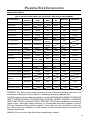
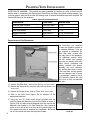
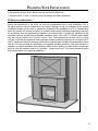
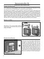
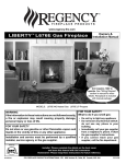
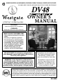
SHERWOOD INDUSTRIES IS AN ENVIRONMENTALLY RESPONSIBLE COMPANY. THIS MANUAL IS PRINTED ON RECYCLED PAPER.
PLEASE KEEP THESE INSTRUCTIONS FOR FUTURE REFERENCE
DV48
BY: SHERWOOD INDUSTRIES LTD
OWNER’S
MANUAL
INSTALLER:
Leave this manual with the appliance.
CONSUMER:
Retain this manual for future reference.
WHAT TO DO IF YOU SMELL GAS
• Open windows/extinguish any open
flame.
• Do not try to light any appliance.
• Do not touch any electrical switch
or use any phone in your building.
• Immediately call your gas supplier
from a neighbour’s phone. Follow
the gas supplier’s instructions.
• If you cannot reach your gas
supplier, call the fire department.
FOR YOUR SAFETY: Do not store or use gasoline or
other flammable vapours and liquids in the vicinity of
this or any other appliance.
This appliance may be installed in an
after-market permanently located,
manufactured (mobile) home,
where not prohibited by local codes.
WARNING: If the information in this manual is
not followed exactly, a fire or explosion may result
causing property damage, personal injury or loss of
life. Installation and service must be performed by a
qualified installer, service agency or the gas supplier.
This appliance is only for use with
the type of gas indicated on the
rating plate. This appliance is not
convertible for use with other gases,
unless a certified kit is used.
Massachusetts installations (Warning): This product must be installed by a licensed plumber or
gas fitter when installed within the Commonwealth of Massachusetts. Other Massachusetts code
requirements: Flexible connector must not be longer than 36in., a shut off valve must be installed;
only direct vent sealed combustion products are approved for bedrooms/bathrooms. A carbon
monoxide detector is required in all rooms containing gas fired direct vent appliances. The fireplace
damper must be removed or welded in the open position prior to installation of a fireplace insert.
50-2003
SAFETY PRECAUTIONS
FOR SAFE INSTALLATION AND OPERATION OF YOUR “WESTGATE”
HEATER, PLEASE CAREFULLY READ THE FOLLOWING INFORMATION:
• All Westgate gas-fired appliances must be
installed in accordance with their instructions.
Carefully read all the instructions in this manual
first. Consult the building authority having
jurisdiction to determine the need for a permit prior
to commencing the installation.
• NOTE: Failure to follow these instructions
could cause a malfunction of the fireplace, which
could result in death, serious bodily injury, and/or
property damage.
• Failure to follow these instructions may also
void your fire insurance and/or warranty.
GENERAL
• Installation and repair should be done by a
qualified service person. The appliance should be
inspected before the first use and, at least, annually
by a qualified service person. More frequent
cleaning may be required due to excessive lint from
carpeting, bedding material, etc. It is imperative
the control compartments, burners and circulating
air passageways of the appliance be kept clean.
• Due to high temperatures, the appliance should
be located out of high traffic areas and away from
furniture and draperies.
Children and adults should be alerted to the
hazards of high surface temperatures and
should stay away to avoid burn or clothing
ignition.
• Young children should be carefully supervised
when in the same room as the appliance.
• Clothing or other flammable materials should
not be placed on or near the appliance.
FOR YOUR SAFETY
• Installation and service must be performed by a
qualified installer, service agency or gas supplier.
• This installation must conform to local codes or,
in the absence of local codes, to the current CAN/
CGA-B149 installation code (Canada) or National
Fuel Gas Code ANSI Z223.1.2 (USA)
2
• To prevent injury, do not allow anyone who is
unfamiliar with the stove to operate it.
• To prevent injury, if the pilot or pilot and
burners have gone out on their own, open
the glass door and wait 5 minutes to air out
before attempting to re-light the stove.
• Always keep the area around these appliances
clear of combustible material, gasoline and other
flammable liquids and vapours.
• These appliances should not be used as a
drying rack for clothing or for hanging Christmas
stockings/decorations.
• Due to the paint curing on the stove, a faint
odor and slight smoking will likely be noticed when
the stove is first used. Open a window until the
smoking stops.
Always connect this gas stove to a vent system and
vent to the outside of the building envelope. Never
vent to another room or inside the building. Make
sure the specified vent pipe is used, properly sized
and of adequate height to provide sufficient draft.
Inspect the venting system annually for blockage
and signs of deterioration.
WARNING: Failure to position the parts in
accordance with the diagrams in this booklet, or
failure to use only parts specifically approved with
this appliance, may result in property damage or
personal injury.
WARNING: Do not operate with the glass front
removed, cracked or broken. Replacement of the
glass should be done by a licensed or qualified
service person.
• Never use solid fuels such as wood, paper,
cardboard, coal, or any flammable liquids, etc., in
this appliance.
• Do not use this heater if any part has been
under water. Immediately call a qualified service
technician to inspect the heater and to replace any
part of the control or gas control systems that have
been under water.
• Do not abuse the glass by striking it or slamming
the door shut.
TABLE OF CONTENTS
Safety Precautions..........................................................................................2
Table of Contents...........................................................................................3
Codes And Approvals......................................................................................5
Specifications.................................................................................................6
Dimensions.........................................................................................6
Rating Label Location...........................................................................6
Rating Label........................................................................................7
Planning Your Installation................................................................................8
Introduction........................................................................................8
Non-Combustible Material Zone............................................................8
Typical Framing - Internal Chase...........................................................9
Typical Framing - External Chase.........................................................10
Typical Framing - Corner.....................................................................11
Typical Framing - Sidewall and Mantel.................................................12
Typical Framing - Raised Hearth..........................................................13
Installation of Fireplace Facing............................................................14
Installation of Optional Facing Trim......................................................15
Installation of Receiver.......................................................................16
Allowable Vent Configurations.............................................................16
Vent Termination Restrictions..............................................................18
Approved Vent Parts...........................................................................19
Installation of Flue Restrictor...............................................................20
TV Installation Above Unit..................................................................21
Installation Set-Up........................................................................................22
Planning Your Installation...................................................................22
Assembly of the Unit..........................................................................22
Securing unit into Position..................................................................22
Installation Of Non-combustible Wall And Hearth Board........................23
Installation Of Venting And Terminations.............................................23
Horizontal Installation........................................................................24
Vertical Termination Installation..........................................................26
Door Removal and Installation............................................................28
Electrical Hook-Up..............................................................................29
Gas Hook-Up.....................................................................................30
LP Gas Conversion.............................................................................30
Firebox Liner Installation....................................................................32
Log Burner / Ember Bed Installation....................................................34
Log Set Installation............................................................................35
Glass Burner Installation.....................................................................37
Porcelain Panel Kit Installation............................................................39
Optional Front Installation..................................................................41
3
TABLE OF CONTENTS
Start-Up & Operation....................................................................................43
Normal Sounds During Operation.......................................................43
Remote Control Operations................................................................43
Technical Data...................................................................................43
System Description............................................................................44
Wall Mounting The Receiver.................................................................45
Operating Procedure..........................................................................45
Air Shutter Adjustment.......................................................................48
Check for Proper Burner Flame...........................................................49
Service / Maintenance..................................................................................50
Lighting Instruction Label..................................................................50
Light Bulb Replacement......................................................................51
Cleaning / Annual Service..................................................................51
Cleaning The Glass............................................................................51
Replacing Glass.................................................................................51
Wiring Harness.............................................................................................52
Troubleshooting..........................................................................................53
Parts List.....................................................................................................55
Parts Diagram...............................................................................................56
Warranty......................................................................................................57
Notes.............................. ...............................................................59
Installation Data Sheet..................................................................................60
4
CODES AND APPROVALS
DIRECT VENT ONLY: This type is identified by the prefix DV. This appliance draws all of its air for
combustion from outside the dwelling, through a specially designed vent pipe system.
This appliance has been tested and approved for installations from 0 feet to 4500 feet (1372 m) above
sea level.
In the USA: The appliance may be installed at higher altitudes. Please refer to your American Gas
Association guidelines which state: the sea level rated input of Gas Designed Appliances installed at
elevations above 2000 (610 m) feet is to be reduced 4% for each 1000 feet (305 m) above sea level.
Refer also to local authorities or codes which have jurisdiction in your area regarding the de-rate
guidelines.
In Canada: When the appliance is installed at elevations above 4500 feet (1372 m), the certified high
altitude rating shall be reduced at the rate of 4% for each additional 1000 feet (305 m).
•
This appliance has been tested by INTERTEK (Warnock Hersey) and found to comply with the
established VENTED GAS FIREPLACE HEATER standards in CANADA and the USA as follows:
VENTED GAS FIREPLACE HEATER (DV48; NG/LPG)
TESTED TO: ANSI Z21.88a-2007/CSA 2.33a-2007 VENTED GAS FIREPLACE HEATERS
CAN/CGA 2.17-M91 GAS FIRED APPLIANCES FOR HIGH ALTITUDES
CSA P.4.1-02 TESTING METHOD FOR MEASURING ANNUAL FIREPLACE EFFICIENCY
This Westgate DV48 Fireplace:
• Has been certified for use with either natural or propane gases. (See rating label.)
• Is not for use with solid fuels.
• Is approved for bedroom or bed sitting room. (IN CANADA: must be installed with a listed wall
thermostat. IN USA: see current ANSI Z223.1 for installation instructions.)
• Must be installed in accordance with local codes. If none exist, use current
installation code CAN/CGA B149 in Canada or ANSI Z223.1/NFPA 54 in the
USA.
• Must be properly connected to an approved venting system and not connected
to a chimney flue serving a separate solid-fuel burning appliance.
IMPORTANT NOTICE (Regarding first fire up): When the unit is turned
on for the first time, it should be turned onto high without the fan on for
the first 4 hours. This will cure the paint, logs, gasket material and other
products used in the manufacturing process. It is advisable to open a
window or door, as the unit will start to smoke and can irritate some people.
After the unit has gone through the first burn, turn the unit off including the
pilot, let the unit get cold then remove the glass door and clean it with a
good gas fireplace glass cleaner, available at your local WESTGATE dealer.
5
SPECIFICATIONS
DIMENSIONS:
ø8” (203mm)
ø5”(127mm)
6 1/16”
(154mm)
17 9/16”
(446mm)
To Gas Line
Connection
20 5/16”
(516mm)
36 13/16” (935mm)
44 5/8” (1133mm)
43”
(1092mm)
52 1/4”
(1327mm)
33 1/4”
(845mm)
41 3/16”
(1046mm)
39 11/16”
(1008mm)
14 3/4”
(375mm)
5 1/2”
(140mm)
To Gas Line
Connection
Figure 1. Dimensions of the Firebox.
RATING LABEL LOCATION:
The Rating and Lighting instruction label is located below the
door frame, underneath the firebox attached to a chain. To
access the label, slide the plate forward out from under the
firebox. Always return it when finished.
Figure 2. Rating/Lighting Label Location.
6
SPECIFICATIONS
RATING LABEL:
vere burns may result. Keep
r other flammable vapors away.
s removed, cracked or broken.
nsed or qualified person! This
be installed with provisions for
operating instructions manual.
n, service or maintenance can
r to owner's manual provided
g instructions accompanying
by a qualified installer, service
PERATING
DO NOT REMOVE THIS LABEL / N'ENLEVEZ PAS CETTE ETIQUETTE
DV48
WH-
VENTED GAS FIREPLACE HEATER ENVIRO MODEL:
FOYER AU GAZ A EVACUATION MODELE ENVIRO:
DV48
NAT: (Gaz naturel)
Certified for use in Canada & USA
Certifié pour installation au
Canada et aux Etats-Unis.
WH# 16354
LPG (Propane)
TESTED TO / TESTÉE SELON LES NORMES:
ANSI Z21.88a-2007/CSA 2.33a-2007 VENTED GAS FIREPLACE HEATERS / FOYER AU GAZ EVACUATION;
CAN/CGA 2.17-M91 GAS FIRED APPLIANCES FOR HIGH ALTITUDES / LES APPAREILS BRULANT GAZ POUR
UTILISATION EN HAUTES ALTITUDES; Can/CSA P.4.1-02 (R2006) TESTING METHOD FOR MEASURING ANNUAL
FIREPLACE EFFICIENCY / LA METHODE D'ESSAI POUR MESURER L'EFFICACITE DE CHEMINEE ANNUELLE.
INPUT (ENTRÉE): NAT: 0-4500 FT (1372 M)
EXACTLY, A FIRE OR EXPLOSION
L INJURY OR LOSS OF LIFE.
any portion of this appliance
oes not operate as the instructions
ndicate, don't try to repair it, call a
ualified service technician. Do not
se tools. Force or attempted repair
may result in a fire or explosion.
o not use this appliance if any
art has been under water.
mmediately call a qualified service
echnician to inspect the appliance
nd to replace any part of the
ontrol system and any gas control
which has been under water.
NS
6. This appliance is equipped with a
completely automatic ignition and
lighting control. The control will
attempt to light the pilot several
timesif necessary. If it is
unsuccessful, it will discontinue
operations. If the appliance does
not operate, follow the
instructions "To Turn Off Gas To
Appliance" and call your service
technician or gas supplier.
Blue LCD Display
ON/OFF Key
THERMOSTAT Key
UP/DOWN Arrow Key
MODE Key
ANCE
F" will be indicated on the display
ommand has been received.
C-11800
MAX: 48,000 BTU (14.07 KW•h)
MIN: 16,000 BTU (4.68 KW•h)
LPG: 0-4500 FT (1372 M)
MAX: 48,000 BTU (14.07 KW•h)
MIN: 17,000 BTU (4.98 KW•h)
MANIFOLD PRESSURE (PRESSION D’ADMISSION):
NAT: 3.5 in. WC (0.87kPa) / 1.6 in. WC (0.40kPa) LPG: 10 in. WC (2.48kPa) / 6.4 in. WC (1.59kPa)
MINIMUM GAS SUPPLY PRESSURE: (PRESSION MINIMALE D'ALIMENTATION DE GAZ PERMISE)
NAT: 5 in. Wc (1.24kPa)
LPG: 12 in. Wc (2.98kPa)
ORIFICE SIZE: (DIMENSIONS DE L’ORIFICE)
NAT: Left # 45 DMS, Right # 41 DMS
LPG: Left # 55 DMS, Right # 53 DMS
PILOT ORIFICE SIZE: (DIMENSIONS DE PILOTER L’ORIFICE)
NAT: # 62 DMS
LPG: Left # 35 DMS
ELECTRICAL RATING:(EXIGENCES ÉLECTRIQUES)
Fan type circulator (Ventilateur circulaire) : 120 volts AC 60 hz / Less than 7 Amperes
CLEARANCES TO COMBUSTIBLES: (DISTANCE OBLIGATOIRE DES COMBUSTIBLES)
Stove side (Côté de poêle): 4 inches (10.2cm), Back (Arriére): 4 inches (10.2cm), Ceiling from bottom of unit (Du fond
d'unité au Plafond): 80” inches (203.2cm), From fireplace frame to side wall (Du frome de la cheminée au mur latéral): 10"
(25.5 cm), From base of the unit to shelf, header, or 12" (30.5cm) mantel (De la base de l'unité à une étagère, un en-tête,
ou un 12" manteau de cheminée): 52.25" (133cm)
VENT PIPE CLEARANCES:(ESPACES LIBRES DE VENTILATION) See manufacturer’s listing, label and installation
instructions. Verifeez l’identifaction, l’etiquette et les instructionsd’installation du fabricant.
VENTED GAS FIREPLACE HEATER - NOT FOR USE WITH SOLID FUELS. MAY BE INSTALLED IN
BEDROOM OR BEDSITTING ROOM (IN CANADA with a listed wall thermostat). THIS APPLIANCE MUST BE PROPERLY
CONNECTED TO A VENTING SYSTEM. ONLY FOR DIRECT DISCHARGE WITHOUT DUCT CONNECTION. This
appliance must be installed as per manufacturers installation instructions and in accordance with local codes if any. If none
exist, use current installation code CAN/CGA B149 in Canada or ANSI Z223.1/NFPA 54 in the USA. This vented gas
fireplace is not for use with air filters. FOR USE WITH FRONTS CERTIFIED WITH THIS APPLIANCE ONLY - NOT FOR
USE WITH GLASS DOORS. This appliance is only for use with the type(s) of gas indicated on the rating plate. A
conversion kit is available for this appliance. This appliance is not convertible for use with other gases, unless a certified kit
is used. Sections of the venting system have not been installed. WARNING: Do not operate the appliance
S
M
A
P
E
L
until all sections have been assembled and installed in accordance with the manufacturers instructions.
FOYER AU GAZ A EVACUATION - NE PAS EMPLOYER AVEC DES COMBUSTIBLES SOLIDES. Cet
appareil peut être installé dans une chambre à coucher ou un studio. Cet appareil doit être branché correctement à un
système de conduits. Uniquement pour l'échappement direct sans raccord de conduit.Cet appareil doit être installé selon les
directives d'installation du manufacturier et selon les codes locaux, s'il y a lieu. Autrement, employez le code d'installation
en vigueur au Canada CAN/CGA B149. Ne pas utilliser de filtre a air avec ce foyer au gaz a evacuation. POUR L'USAGE
AVEC LES DEVANTS CERTIFIES AVEC CET APPAREIL SEULEMENT - PAS POUR L'USAGE AVEC PORTES VITREES.
Cet apperareil doit etre utilise uniquement avec le type de gaz indique sur la plaque. Cet appareil ne peut etre converti a
d’autres gaz sauf si une trouse de conversion certifee est utilisee. ADVERTISSEMENT: Ne pas utiliser l’appareil
tant que toutes les sections n’ont pas ete assemblees et installees selon les instructions du fabricant.
MOBILE HOME: May be installed in an aftermarket, permanently located, manufactured home (USA only) or mobile home,
where not prohibited by local codes. See owner's manual for details. This appliance must be installed in accordance with the
current Standard for Mobile Homes, CAN/CSA Z240, or the Manufactured Home Construction and Safety Standard, Title 24
CFR, Part 3280, or when such standard is not applicable, the current Standard for Fire Safety Criteria for Manufactured
Home Installations, sites, and Communitties, ANSI/NFPA 501A.
LA MAISON MOBILE : Peut être installé dans une maison mobile. Cet appareil doit être installé conformement aux Normes
actuelles pour Maisons Mobiles, le BOITE/CSA Z240, ou les Normes de Construction et de Sureté des Maisons Préfabriquées (Titre 24 CFR, la Partie 3280). Quand ces Normes ne sont pas en vigueur, il faut suivre les criteres pour la sureté
(contre les increndies) et pour la construction des Maisons Pré-fabriquées, leurs sites, ANSI/NFPA 501A, et des
communautées aux Instructions du manufacturier.
MANUFACTURED BY (FABRIQUE PAR) : SHERWOOD INDUSTRIES LTD. 6782 OLDFIELD RD. SAANICHTON, BC,
DUE TO HIGH SURFACE TEMPERATURES KEEP CHILDREN, CLOTHING, AND FURNITURE AWAY
DUES AUX TEMPERATURES ELEVEES, GARDEZ LES ENFANTS, LES VETEMENT ET LES MEUBLES ELOIGNES
DATE OF MANUFACTURE: DATE DE FABRICATION:
J
F
M
A
M
J
J
A
S
O
N
D
2009
2010
2011
2012
Figure 3. Rating Label.
7
PLANNING YOUR INSTALLATION
INTRODUCTION:
This section of the owner’s manual is for the use of qualified technicians only. Fireplace placement,
hearths, facings, mantles, and venting terminations will be covered, as well as the gas and electric
systems. There are several installation safety guidelines that must be adhered to. Please carefully read
the safety precautions at the front of this manual.
Warning: Clearances must be sufficient to allow access for maintenance and service.
NON-COMBUSTIBLE MATERIAL ZONE:
This installation guide will show you many options for installing your new DV48. Some options include
external chases, internal chases, rock facing and corner installations. No matter what direction your
installation takes, this illustrations shows an area where no combustible building products may go. This
illustration applies to any and all installations for the DV48 and should be used as the first reference
before any others. Failure to comply with this requirement can lead to elevated operating temperatures,
degradation of materials or even result in fire. If you are un-clear about any details contained here,
consult with your retailer prior to installation.
377/8”
(962mm)
261/2”
(673mm)
NON-COMBUSTIBLE
MATERIAL ONLY ZONES
73/8”
(187mm)
445/8”
(1133mm)
Nailing Flange
Face
13”
(330mm)
Top View
131/2”
(343mm)
Nailing Flange
Face
**80”
(2032mm)
**521/4”
(1327mm)
Front View
Side View
** Dimensions taken from the base of the unit.
Figure 4. Non-Combustible Material Zone.
8
PLANNING YOUR INSTALLATION
TYPICAL FRAMING - INTERNAL CHASE:
Wall Thimble
Header
Venting
External Wall
Flooring
Figure 5. Typical Framing for Internal Chase - General.
261/2” (673mm)
Chase Minimum
Depth
445/8”
(1133mm)
Minimum
13” (330mm)
Maximum
**521/4”
(1327mm)
Minimum
**80”
(2032mm)
to Internal
Ceiling
**697/16”
(1764mm)
to Vent
**521/4”
(1327mm)
to Header
** Minimum Height from the base of the unit.
Figure 6. Typical Framing for Internal Chase - Detailed.
9
PLANNING YOUR INSTALLATION
TYPICAL FRAMING - EXTERNAL CHASE:
External Wall
Wall Thimble
Venting
Non-Combustible
Facing (Supplied)
Header
Hearth Protector
(Supplied)
Flooring
Figure 7. Typical Framing for External Chase - General.
261/2” (673mm)
Chase Minimum
Depth
445/8”
(1133mm)
Minimum
**697/16”
(1764mm)
to Vent
**521/4”
(1327mm)
to Header
**80”
(2032mm)
to Internal
Ceiling
** Minimum Height from the base of the unit.
Figure 8. Typical Framing for External Chase - Detailed.
10
PLANNING YOUR INSTALLATION
TYPICAL FRAMING - CORNER:
Wall Thimble
Venting
Wall Board
Shelf
Fireplace Riser
Raised Hearth
Figure 9. Typical Framing for Corner - General.
1713/16”
(452mm)
41/8”
(105mm)
41/8”
(105mm)
457/16”
(1154mm)
Minimum
445/8”
(1133mm)
Minimum
9015/16”
(2310mm)
Minimum
13” (330mm)
Maximum
521/4” (1327mm)
Minimum to
Header/Shelf
Height from Base
of Unit
Figure 10. Typical Framing for Corner - Detailed.
11
PLANNING YOUR INSTALLATION
TYPICAL FRAMING - SIDEWALL AND MANTEL:
Non-Combustible
Facing
Mantel
The
mantel’s
maximum
overhang is 10” (254mm) at
the minimum height of 521⁄4”
(1327mm) measured from the
base of the fireplace.
Mantel Leg
The mantel can extend 1”
(25.4mm) further for every
1” (25.4mm) of height it is
installed over the minimum
height, as shown in Figure 12.
External Wall
Non-combustible mantels and
mantel legs are not limited to
these dimensions.
Sidewall
Mantel
temperatures
are
monitored during testing and
can reach 117°F (47°C) above
room temperatures. Make sure
the finish on your mantel is
suitable for temperatures of
this range.
Raised Hearth
Flooring
Figure 11. Typical Framing for Sidewalls & Mantel - General.
Combustible
Mantel Leg
Sidewall
445/8” (1134mm)
Minimum
Framing Width
Allowable Mantel
Installations
10” (254mm)
Minimum
Fireplace Flange
to Sidewall
45
4” (102mm)
11/4”
(32mm)
10” (254mm)
Maximum
Overhang at
Minimum Height
61/16” (154mm)
Minimum
Framing to
Sidewall
10” (254mm) Minimum
Fireplace Flange to
Combustible Leg
181/2” (470mm)
Minimum
Mantel Height
from Top Flange
521/4” (1327mm)
Minimum
Fireplace Base to
Combustible
Mantel
Figure 12. Typical Framing for Sidewalls & Mantel - Detailed.
12
10” (254mm)
Minimum
Fireplace
Flange to
Combustible
Leg
Combustible
Mantel
Combustible
Mantel Leg
PLANNING YOUR INSTALLATION
TYPICAL FRAMING - RAISED HEARTH:
Warning: Failure to follow these guidelines may result in elevate operating temperatures,
an inability to remove or install the door, or install the optional fronts that are
available for this unit.
A non-combustible Hearth
Insulation
Board
is
required (supplied) to be
installed between any noncombustible hearth covering
and any combustible flooring
beneath.
The design of the unit is such
the fireplace must be raised
by the same distance as any
additional hearth covering
or riser that are added in
front of the fireplace.
Fireplace Platform
Non-Combustible
Hearth Covering
Non-Combustible
Insulating Board
Figure 13. Typical Framing for a Raised Hearth - General.
Figure 14 shows a raised
hearth made of a wooden
construction hearth riser
(B), covered with the
insulation board provided
and then covered with noncombustible slate (A). The
thickness of the riser (B) is
4” (102mm). The thickness
of the slate (A) is 2”
(52mm). A+B=C which is 6”
(152mm). In summary, the
fireplace must be raised by
the same thickness of any
material added in front of
the fireplace, with exception
of the 1⁄2” (13mm) Hearth
Insulation Board that was
provided with the unit.
If the raised hearth is
deeper and widerthan the
Insulation Board provided
with the unit, addition
non-combustible
building
materials such as Backer
Board (cement board) can
be used to build up to the
same thickness around the
Insulation Board.
Combustible Riser
Non-Combustible
Hearth Covering
521/4” (1327mm)
Minimum to
Combustible
Header Height
from Base of Unit
Hearth Insulation
1/2” (13mm)
(Provided)
A
C
B
Fireplace Platform
Combustible Riser
Combustible Flooring
Figure 14. Typical Framing for a Raised Hearth - Detailed.
13
PLANNING YOUR INSTALLATION
Window Door Frame
All header, ceiling or shelf dimensions are
measured from the floor that the fireplace sits
on. Failure to maintain minimum installation
dimensions can lead to elevated temperatures,
fire or personal injury.
IMPORTANT: DO NOT
INSTALL HEARTH MATERIAL
ABOVE THIS FLANGE.
Non-Combustible
Hearth Pad (Supplied)
WARNING! If hearth material is
installed above this flange, you will
be unable to install or remove the
fireplace door or optional front.
Door Latch
Fireplace Bottom
Front Edge
Figure 15. Fireplace Section for a Raised Hearth - WARNING.
INSTALLATION OF FIREPLACE FACING:
Non-Combustible
Facing (Supplied)
Mantel
Standard
Wall Board
Stone Facing
Hearth
Fireplace
Door
Figure 16. Typical Facing for the Fireplace - General.
Fireplace Door
Non-Combustible
Board (Supplied)
1/2”
(13mm)
1/2”
(13mm)
5/8”
(16mm)
Minimum Air Gap
Tile or other non-combustible
facing including grout or cement
Optional Fronts
Figure 17. Option 1 - Fireplace Facing Less Than 1”
(25.4mm) Thick With Optional Front Installed.
14
There are a number of
optional fronts available for
use with the DV48. These
fronts lift on and off of the
fireplace, providing access
to the fireplace for regular
maintenance and service.
You have 3 possible scenarios
when installing facing to your
fireplace installation. Care
must be taken to ensure
proper
clearances
are
maintained. Clearances are
required between optional
fronts and any stone work
applied to your fireplace
installation.
Failure
to
maintain this clearance will
lead to elevated operating
temperatures and possible
discoloration of materials and
or fronts.
Three (3) possible installations include:
1) For fireplace facing less than 1” thick (total facing
and non-combustible board combined) with an
optional front installed.
2) For fireplace facing greater than 1” thick with an
optional front installed.
3) For any fireplace facing without an optional front
installed.
Figures 17 to 19 highlight the relationships between
the fireplace, optional front, and facing installed.
PLANNING YOUR INSTALLATION
Fireplace Door
Optional Edging
(Supplied)
Fireplace Door
Non-Combustible
Board (Supplied)
Non-Combustible
Board (Supplied)
1/2”
1/2”
(13mm)
(13mm)
Any Thickness
Optional Fronts
3/4” (19mm)
Minimum Air Gap
Tile or other non-combustible
facing including grout or cement
Tile or other non-combustible
facing including grout or cement
Figure 18. Option 2 - Fireplace Facing More Than 1”
(25.4mm) Thick With Optional Fronts Installed.
Figure 19. Option 3 - Any Fireplace Facing Without
Optional Front Installed.
INSTALLATION OF OPTIONAL FACING TRIM:
The Optional Facing Trim supplied with
your fireplace is designed to fit between
the supplied non-combustible board and
the fireplace drywall flange.
IMPORTANT: When installing the wall
board, leave a small gap between it and
the fireplace drywall flange.
Insert the long side of the Right Trim into
this gap and secure with drywall screws
where holes are prvided. Complete it at
the top and left edges. Other fireplace
facing can then be installed over the
exposed flange
Figure 20. Optional Facing Trim Installation - General.
Fireplace Door
Supplied Non-Combustible Board
1/2”
Fireplace Drywall Flange
Optional Edging Supplied
(Right Side Shown)
Drywall Screw
Figure 21. Optional Facing Trim Installation - Right Detail.
15
PLANNING YOUR INSTALLATION
INSTALLATION OF RECEIVER:
Electrical Box
(Supplied)
Wall Stud
Receiver Cover
Receiver
Figure 22. Receiver Installation.
The Receiver is the heart of the remote control system. You need to access this receiver after installation
to change the batteries (for operation during a power failure), to program a new remote / receiver
combination and to operate a manual override should you lose your remote control or the batteries in the
remote control lose their power.
The Receiver is connected to the fireplace with a wire harness that has a maximum length of 8 ft (3m).
The connection point on the fireplace is on the right side of the unit, where the gas valve and electronic
ignition module is located. Because of the 8 ft (3m) limitation in the wiring harness, the receiver needs
to be mounted to the right side of the fireplace. An electrical box is provided for the receiver. Mount this
electrical box as you would any electrical outlet or switch box. Thread the cable and connector through
the back of the electrical box and connect it to the rear of the receiver. Secure the receiver into the
electrical box. Once the facing of the fireplace installation is complete, install the receiver cover, supplied
with the unit as shown. The receiver cover also functions as a switch plate and has a provision for access
the program button, critical for remote control operation.
Review the section in this manual regarding the remote control operations for more information on the
functions of the receiver.
ALLOWABLE VENT CONFIGURATIONS:
The vent chart, in Figure 23, illustrates the vent configurations that have been tested and approved for
use with this appliance. 45˚ elbows are acceptable for this installation and may be used instead of 90˚
elbows. You may use two (2) 45˚ elbows for every 90˚ elbow shown in this chart.
This appliance is also approved for use with 5” x 8” flex venting. Only use flexible venting that is approved
for fireplace applications. Flex vent runs must comply with the same limitations as the rigid vent chart
shown here. Flexible vent runs greater than 8’ total are not recommended. Mixed vent runs of both
Flexible and rigid venting are allowed providing all the proper connectors are utilized. See your vent
providers’ catalogue for flex to rigid or rigid to flex adaptor numbers.
16
PLANNING YOUR INSTALLATION
* Horizontal Vent Sections rise 1/4”/ft (21mm/m) *
40’ (12.19m)
35’ (10.67m)
The restrictor settings
shown in Figure 23,
are
recommended.
Installation factors such
as altitude, prevailing
weather conditions such
as temperature or wind,
or the number of elbows
used may affect your
final restrictor settings.
To little restriction may
cause pilot outages or
reduced efficiencies. Too
much restriction may lead
to elevated operating
temperatures, poor flame
appearances, sooting or
carbon deposits building
on burner effects or
window glass.
30’ (9.14m)
25’ (7.62m)
20’ (6.10m)
15’ (4.57m)
Only use the restrictors
supplied
with
this
appliance.
9’6” (2.90m)
20’ (6.10m)
15’ (4.57m)
10’ (3.05m)
5’ (1.52m)
1’ (0.305m)
5’3” (1.60m)
Figure 23. Allowable Vent Configurations Chart.
17
PLANNING YOUR INSTALLATION
VENT TERMINATION RESTRICTIONS:
QUALIFIED INSTALLERS ONLY
N
O
H
D E
L
B
C
B
B
Fixed
Closed
F
Openable
B
G
Fixed
Openable Closed
A
Termination Cap
G
M
J
Air Supply Inlet
G
Gas Meter
K
I
Restriction Zone
A
(Termination not allowed)
Figure 24. Vent Termination Restrictions, refer to Table 1.
Table 1: Vent termination clearances, refer to Figure 24.
Letter
Canadian Installation
A
B
1
2
US Installation
12 in (30 cm)
12 in (30 cm)
Description
Clearance above grade, verandah, porch, deck, or
balcony.
9 in (23 cm)
Clearance from window or door that may be opened.
C
12 in (30 cm)*
Clearance from permanently closed window (to prevent
condensation).
D
191⁄4 in (49 cm)
Vertical clearance to ventilated soffit located above the
terminal, within a horizontal distance of 2 ft (60 cm)
from center line of terminal.
E
191⁄4 in (49 cm)
Clearance to unventilated soffit.
F
171⁄4 in (44 cm)*
Clearance to outside corner.
G
171⁄4 in (44 cm)
Clearance to inside corner.
H
3 ft (91 cm) within a height
of 15 ft (4.5 m) above the
meter/regulator assembly
3 ft (91 cm) within a height
of 15 ft (4.5 m) above the
meter/regulator assembly*
Clearance to each side of center line extended above
meter/regulator assembly.
I
3 ft (91 cm)
3 ft (91 cm)*
Radial clearance around service regulator vent outlet.
J
12 in (30 cm)
9 in (23 cm)
Clearance to non-mechanical air supply inlet to building,
or the combustion air inlet to any other appliance.
K
6 ft (1.83 m)
L
7 ft (2.13 m)t
3 ft (91 cm) above if within 10 Clearance to mechanical air supply inlet.
ft (3 m) horizontally
7 ft (2.13 m)*t
Clearance above paved sidewalk or paved driveway
located on public property.
M
191⁄4 in (49 cm)+
N
12 in (30 cm)*
Clearance horizontally to any surface (such as an exterior wall) for vertical terminations.
O
12 in (30 cm)
Clearance above roof line for vertical terminations.
Clearance under verandah, porch, deck, or balcony.
1 In accordance with the current CSA B149, Natural Gas and Propane Installation Code.
2 In accordance with the current ANSI Z223.1 NFPA 54, National Fuel Gas Code.
* These numbers are only estimates. Clearance in accordance with installation codes and the requirements of the gas supplier.
t
A vent shall not terminate directly above a side walk or paved driveway that is located between two single family dwellings and it serves both dwellings.
+
Permitted only if verandah, porch, deck, or balcony is fully open on a minimum of two sides beneath the floor.
NOTE: Venting terminals shall not be recessed into walls or siding.
18
PLANNING YOUR INSTALLATION
APPROVED VENT PARTS:
Table 2: Vent part numbers (Must state if galvanized or black wanted, PART NUMBERS).
Part Description
Simpson
Duravent
Security
Chim.
American
Metal
Selkirk
Int.
Metal-Fab
EXCELDirect
6” Pipe Length
58DVA-06
SV5L6
5D7
5DT-06
5D6
TC-5DL6
9” Pipe Length
58DVA-09
12” Pipe Length
58DVA-12
SV5L12
5D12
5DT-12
5D12
TC-5DL1
24” Pipe Length
58DVA-24
SV5L24
5D2
5DT-24
5D24
TC-5DL2
36” Pipe Length
58DVA-36
SV5L36
5D3
5DT-36
5D36
48” Pipe Length
58DVA-48
SV5L48
5D4
5DT-48
5D48
60” Pipe Length
58DVA-60
8 1⁄2” Pipe Extension
58DVA-08A
SV5LA12(12”)
5D7A
5D12A
5DT-AJ12
5DAL
16” Pipe Extension
58DVA-16A
SV5LA24(24”)
5D16A
5D26A
5DT-09
TC-5DL4
Flexible Length, 36”
TC-5DLF
12” Adjustable Length
TC-5DLT
45° Elbow
46DVA-E45
SV5E45
5D45L
5DT-EL45
5D45L
TE-5DE45
90° Elbow
46DVA-E90
SV5E90
5D90L
5DT-EL90
5D90L
TE-5DE90
Roof Flashing
58DVA-F6
SV5F /
SV5FA / SV5FB
5DF12
5DT-AF6
5DT-AF12
5DF
XF-6EF / XF-6EFA
/XF-6EFB
Storm Collar
58DVA-SC
SV5FC
5DSC
5DT-SC
5DSC
TM-SC
Ceiling Firestop
58DVA-FS
SV5BF
5DFSP
5DT-FS
TM-5CS
Wall Firestop
58DVA-WFS
5DFS
Wall Thimble
58DVA-WT
SV5RMS
5DWT
5DT-WT
5DWT
TM-5WT
Horiz. Square Termination
58DVA-HC-*
SV5CHC
5DHCS
5DT-HC
5DHT
TM-5HT/TM-5DHT
Horiz. Round Termination
58DVA-HRCS
Horizontal Sconce
Termination
58DVA-HSC-*
5DHC
Vert. Termination, High
Wind
58DVA-VCH
SV5CGV
5DVC
5DT-VT
5DVT
TM-5VT
Vinyl Siding Standoff
58DVA-VSS
SV5VS
5DHVS
5DT-VS
5DVS
TM-VSS
Flex Venting 5” and 8”
Duraflex
*Several color choices
IMPORTANT: This chart covers the major components for each of these manufacturers only. Refer to the
manufacturers’ catalogue for further details on roof flashings and other installation items
The DV48 fireplace has been tested and certified for use with AMERICAN METAL PRODUCTS “AMERIVENT
DIRECT”, SIMPSON DURAVENT TYPE GS PIPE FOR GAS STOVES. SECURITY CHIMNEY’S “SECURE VENT
DIRECT VENT SYSTEM” and SELKIRK “DIRECT-TEMP VENT SYSTEM” kits are available for horizontal and
vertical venting. When using Simpson Duravent, it is recommended that, before installation, a bead of
RTV High Temperature Silicone should be applied to each outer vent joint, and Mil-Pac to each inner
joint. When planning an installation, it will be necessary to select the proper length of vent pipe for the
particular requirements.
WARNING: Do not mix parts from different vent manufacturers’ systems.
19
PLANNING YOUR INSTALLATION
EXCEPTION TO WARNING: This product has been evaluated by Intertek for using a Direct Vent GS
starting collar in conjunction with Secure Vent, Direct-Temp, and Ameri Vent Direct venting systems. Use
of these systems with the Direct Vent GS starting collar is deemed acceptable and does not affect the
Intertek WH listing of the appliance.
Table 3: Approved Vent Manufacturers
Manufacturer
Trade Name
Nominal Sizes
American Metal Products
AmeriVent Direct
5” x 8”
Security Chimneys International LTD
Secure Vent
5” x 8”
Selkirk Metalbestos
Direct-Temp
5” x 8”
Simpson Dura-Vent
Direct Vent GS
5” x 8” Co-axial Vent
EXCELDirect
ICC
5” x 8”
INSTALLATION OF FLUE RESTRICTOR:
Flue Restrictors are necessary
to keep the fireplace running at
its intended efficiency. They are
also required to counteract the
effect that taller vertical vent
runs may have on the appliance.
The additional venting action
that tall vertical vent systems
may have can result in poor pilot
and/or burner operations and
possibly nuisance shut downs.
Generally, the vent restriction
may be less than what is shown
in the vent chart, but not greater.
The vent restrictor size is shown
in percentages, meaning that a
40% restrictor restricts the vent
40% from its fully un-restricted
vent size.
Figre 25: Installation of Flue Restrictor.
1) Remove the Glass Door; refer to DOOR REMOVAL
AND INSTALLATION.
2) Remove the Burner and/or Log Set; refer to BURNER REMOVAL
INSTALLATION.
AND
3) Remove the firebox liners; refer to FIREBOX LINER INSTALLATION.
4) Refer to the Vent Chart (Figure 23) for selection of the
appropriate Restrictor.
5) Using the two (2) sheet metal screws provided with the
restrictor, fasten the Restrictor into the Flue Outlet as shown in
Figures 25 & 26. Make sure the diagonal holes line up with the
diagonal holes located in the Flue Outlet Box Use a powered
driver to drive the screw in as they have to pass through one
thin gauge steel plate to complete the installation. Be careful Figre 26: Installation of Flue Restrictor
not to over-torque the screw and strip the threads.
- Close-Up.
20
PLANNING YOUR INSTALLATION
6) Re-install the Firebox Liners, Burners and log sets and the Glass Door.
7) Run the unit for 1⁄2 hour to check for proper operations and flame appearance.
TV INSTALLATION ABOVE UNIT:
During the development of the DV48, we took into consideration that in some installations TV’s or
flat panel monitors may be located above the mantel. Although we can not anticipate every possible
installation variable, we took time to evaluate the suitability of the installation of a TV or Plasma display
above the mantel. We carried out testing to evaluate what possible operating temperatures that may
be experienced when the appliance was installed in an internal chase. A mantel was installed with the
maximum overhang at the minimum allowable installation height, with a full 13” (330mm) shelf installed
over the unit (see section NON-COMBUSTIBLE MATERIAL ZONE). The area above the mantel, within 4 inches
(102mm) of the wall was measured under maximum operating conditions and found to not exceed 120°F
(49°C). Variations of mantel overhangs, shelf depths or ceiling heights will affect this temperature. Please
refer the TV owner’s manual for information on acceptable operating conditions. Care must be taken to
evaluate your specific installation and operating conditions when deciding to install electronic equipment
above or near this appliance when it is in operation. Always consult your TVs owner’s manual to ensure
that this application is an approved installation.
Figre 27: Installation of TV Above the Unit.
21
INSTALLATION SET-UP
QUALIFIED INSTALLERS ONLY
PLANNING YOUR INSTALLATION:
Prior to starting your venting installation, refer to the section on Allowable Vent Configurations to make
sure your plans fall into the allowable limits of horizontal and vertical installations.
When planning your installation, it will be necessary to select the proper length of vent pipe for your
particular requirements. For horizontal installations, refer to the section on Clearances to Combustibles to
determine the minimum clearance from the rear of the appliance to the wall. It is also important to note
the wall thickness. Select the amount of vertical rise desired for “vertical-to- horizontal” type installations.
To determine the length of vent pipe required for vertical installations, measure the distance from the
appliance flue outlet to the ceiling, the ceiling thickness, the vertical rise in an attic or second story, and
allow for sufficient vent height above the roofline. For two-story applications, firestops are required at
each floor level. If an offset is needed in the attic, additional pipe and elbows will be required.
ASSEMBLY OF THE UNIT:
Left & Right
Drywall Support
Using eight (8) T-20 screws provided, install the
drywall supports right and left as well as the heat
shield in the middle.
Heat Shield
Figre 28: Installation of Supports & Heat shield.
SECURING UNIT INTO POSITION:
Drywall Supports (x2)
Side
Stand-Offs
(x4)
Floor Nailing Flanges (on both sides)
Figre 29: Securing the Unit.
22
Once the unit is in its final position, confirm that you
have access to power, gas supply, that your noncombustible zone requirements are met, that you
meet all the minimum vent requirements, and that
you’re planned vent terminal location will meet all of
the vent termination clearances. Secure the unit to the
floor, with at least four (4) wood screws, two (2) on
either side of the unit’s bottom nailing flange. Secure
the side stand-offs to the framing members using four
(4) wood screws, one (1) for each stand-off and to the
header, one (1) wood screw for each drywall support.
INSTALLATION SET-UP
QUALIFIED INSTALLERS ONLY
INSTALLATION OF NON-COMBUSTIBLE WALL AND HEARTH BOARD:
Install the non-combustible wall board and hearth
protector provided with the unit. The side boards
are interchangeable and are secured with drywall
screws (3⁄4” screws provided), three (3) to each side
of the unit and three (3) to each side frame member.
The top board is secured with three (3) drywall
screws along the top frame (header), three (3)
along the top nailing flange of the unit and two (2)
on each vertical frame member. Also secure the top
wall board to the heat shield behind it with two (2)
screws and each drywall support upright with two
(2) screws. See the section on hearth installation
for installing the hearth protector, required with the
installation of this unit. All the screws required to
attach the wall board sides and top to the unit have
corresponding holes already located on the units
nailing flanges, drywall supports and heat shield.
Non-Combustible
Wall Board Top
Non-Combustible
Wall Board Sides
Non-Combustible
Hearth Ptotection
Figre 30: Installation of Wall & Hearth Board.
INSTALLATION OF VENTING AND TERMINATIONS:
Heat Shield
Horizontal Termination
Vertical Termination
Wall Thimble
Storm Collar
90° Elbow
Roof Flashing
Fire Stop
Vent Section(s)
Minimum - 18”
Recommended - 2’
Vent Sections
45° Elbow
45° Elbow
Figre 31: Typical Minimum Vent Configurations
- Horizontal Terminated.
Figre 32: Typical Vent Configurations
- Vertical Terminated.
23
INSTALLATION SET-UP
Read all instructions carefully before starting the installation. Failure to follow these instructions may
create a fire or other safety hazard, and will void the warranty.
INSTALLATION PRECAUTIONS:
• Do not install any damaged venting or vent components.
• Do not modify any vent or termination component.
• Do not install any vent component that is not an approved vent component for this appliance.
• Do not use any instruction other that those included in this manual or those included by the vent
component manufacturer with the venting. When there are discrepancies between the two, this manual
will be considered the final authority.
Consult your local building codes before beginning the installation.
WARNING
• Always maintain required clearances (air spaces) to nearby combustibles to prevent a
fire hazard. Do not fill air spaces with insulation. Unless stated otherwise, clearances on
horizontal vent sections are 2” (51mm) to combustible materials. Clearances to vertical
vent sections are 1” (25mm) to combustible clearances.
• The fireplace and vent system must be vented directly to the outside of the building. Each
direct vent fireplace must use its own separate vent system. Common vent systems are
prohibited.
HORIZONTAL INSTALLATION:
Step 1. Set the fireplace in its desired location. Check to determine if wall studs or roof rafters are in the
way when the venting system is attached. If this is the case, you may want to adjust the location
of the appliance.
Step 2. Direct Vent pipe and fittings are designed with special twist-lock connections. Assemble the
desired combination of pipe and elbows to the appliance. See the sections on TYPICAL FRAMING
- INTERNAL CHASE, EXTERNAL CHASE or CORNER INSTALLATION for some of the possible vent pathway
options. All installations must fall within the Allowable Vent Configurations shown in Figure 20.
Notes:
(1) Twist-lock procedure: Four (4) indentations, located on
the female ends of pipes and fittings, are designed to slide
straight onto the male ends of adjacent pipes and fittings,
by orienting the four pipe indentations so they match and
slide into the four (4) entry slots on the male ends. Push
the pipe sections completely together, then twist-lock one
section clockwise approximately one-quarter turn, until
the two sections are fully locked.
(2) Horizontal runs of vent must be supported every 3 feet
(915mm). Wall Straps are available for this purpose.
(3) Sealant is only necessary on the outer tube of the GS Pipe.
Run a 1⁄8 inch (3mm) wide bead of sealant around the
male end of the outer sleeve, as shown in Figure 33, and
twist-lock the pipes or fittings together.
Figre 33: Twist-Lock Connection.
Step 3. With the adaptor and pipe attached to the fireplace, slide the fireplace into its correct location,
and mark the wall for a square hole of the appropriate size. Use 11”x11” (280x280mm) square
hole for 8” x 5” pipe. The center of the square hole should line up with the centerline of the
24
INSTALLATION SET-UP
horizontal pipe, as shown in Figure 34. Cut and frame the square hole in the exterior wall where
the vent will be terminated. If the wall being penetrated is constructed of non-combustible
material, i.e. masonry block or concrete, a hole
with zero clearance to the pipe is acceptable.
Notes:
(1) Any horizontal run of vent must have a 1⁄4 inch (6mm)
rise for every 1 foot (305mm) of run towards the
termination. Never allow the vent to run downward.
This could cause high temperatures and may present
the possibility of a fire.
(2) The
location
of
the
horizontal vent termination
on an exterior wall must
meet all local and national
building codes, and must
not be easily blocked or
obstructed.
Termination
clearances must comply
with
VENT
TERMINATION
RESTRICTIONS section.
Step 4. For a Square Horizontal
Vent
Termination,
place the vent cap
Figre 35: Fastening
in the center of the Horizontal Termination Cap
in Place.
square hole and attach
to the exterior wall
with the four wood screws provided
(refer to Figure 35). Before attaching
the Vent termination to the exterior
wall, run a bead of non-hardening
sealant around its outside edges, so
as to make a seal between it and
the wall. If you are using a Round
Horizontal Vent Termination, place an
exterior Wall Firestop over the square
hole. Run a bead of non-hardening
sealant around the edges of the Wall
Firestop, and attach the Wall Firestop
to the wall with the four wood screws
provided. The arrow on the vent cap
should be pointing up. Ensure that
proper clearances to combustible
materials are maintained.
Notes:
(1) The four (4) wood screws provided should
be replaced with appropriate fasteners for
stucco, brick, concrete, or other types of
sidings.
Figre 34: Horizontal Venting and Cut Away.
Figre 36: Installation of Vinyl Siding Standoff.
25
INSTALLATION SET-UP
(2) For buildings with vinyl siding, a Vinyl Siding Standoff should be
installed between the vent cap and the wall (see Figure 36). Attach
the Vinyl Siding Standoff to the Horizontal Vent Termination.
The Vinyl Siding Standoff prevents excessive heat from possibly
melting the vinyl siding material. Note that the Square Horizontal
Vent Termination bolts onto the flat portion of the Vinyl Siding
Standoff, (Shaded area shown in Figure 36), so that an air space
will exist between the wall and the Vent Termination.
11/4”
(32mm)
Step 5. Before connecting the horizontal run of vent pipe to the vent
termination, slide the Wall Firestop over the vent pipe on the
interior side of the wall.
Step 6. Slide the appliance and vent assembly towards the wall,
carefully inserting the vent pipe into the vent cap assembly. Figre 37: Installation of Vent Pipe
It is important that the vent pipe extend into the vent cap
to Termination.
sufficient distance so as to result in a minimum pipe overlap
of 11⁄4 inches (32mm). Secure the connection between the
vent pipe and the vent cap. For square caps, attach the two
sheet metal strips extending from the vent cap assembly
into the outer wall of the vent pipe. Use the two sheet metal
screws provided to connect the sheet metal strips to the pipe
section. For round caps, use three sheet metal screws and
attach cap to pipe section (see Figure 34).
Step 7. Slide the Wall Firestop up to the wall surface and attach with
screws provided (see Figure 38).
VERTICAL TERMINATION INSTALLATION:
Figre 38: Installation of Wall
Firestop.
Step 1. Maintain clearances between venting and combustible building materials as stated earlier in this
section. Do not pack air spaces with insulation. Check with the Allowable Vent Configurations
page when planning your installation to ensure the vertical and horizontal elements of your
installation are within these limits.
Step 2. Set the fireplace in its desired location. Drop a plum
bob down from the ceiling to the position of the
appliance flue exit, and mark the location where the
vent will penetrate the ceiling. Drill a small hole at
this point. Next, drop a plumb bob from the roof to
the hole previously drilled in the ceiling, and mark
the spot where the vent will penetrate the roof.
Determine if ceiling joists, roof rafters, or other
framing will obstruct the venting system. You may
wish to relocate the appliance, or to offset, to avoid
cutting load bearing members.
Step 3. To install the Ceiling Firestop in a flat ceiling, cut
a square hole in the ceiling 11”x11” (280x280mm)
square for 8” x 5” pipe, centered on the hole drilled in
Step 2. Frame the hole as shown in Figure 39 .
26
Figre 39: Installation of Ceiling Firestop.
INSTALLATION SET-UP
Step 4. Assemble the desired lengths of galvanized Pipe and Elbows necessary to reach from the
Appliance Adaptor up through the Ceiling Firestop. Ensure that all Pipe and Elbow connections
are in their fully twist-locked position.
Step 5. Cut a hole in the roof centered on the small drill hole
placed in the roof in Step 2. The hole should be of
sufficient size to meet the minimum requirements for
clearance to combustibles, as specified earlier. Continue
to assemble lengths of Pipe and Elbows necessary to
reach from the Ceiling Firestop up through the roof line.
Notes:
(1) If an offset is necessary in the attic to avoid obstructions, it
is important to support the vent pipe every 3 feet, to avoid
excessive stress on the Elbows, and possible separation. Wall
Straps are available for this purpose (see Figure 40).
(2) Whenever possible, use 45° Elbows, instead of 90° Elbows.
The 45° Elbow offers less restriction to the flow of flue gases
and intake air.
Step 6. Slip the flashing over the Pipe Section(s) protruding
through the roof. Use a non-hardening sealant between
the Flashing and the roof to prevent water leakage.
Secure the base of the Flashing to the roof with roofing
nails. Ensure the roofing material overlaps the top edge
of the Flashing as shown in Figure 41. Verify that you
have at least the minimum clearance to combustibles at
the roofline.
Step 7. Continue to add Pipe Sections until the height of the Vent
Cap meets the minimum building code requirements
described by your local
codes. In the absence of
local codes, make sure
the terminal is 2 feet
(610mm) above anything
within 10 feet (3046mm)
of the vent (refer to
Figure 43 & Table 4 for
clearances for different
pitches). Note that for
steep roof pitches, the
vent height must be
increased. In high wind
conditions, nearby trees,
adjoining rooflines, steep
pitched roofs, and other
similar factors can result
in poor draft, or downdrafting. In these cases,
increasing the vent height
may solve this problem.
Figre 40: Vertical Installation using.
Figre 41: Installation of Flashing & Vertical Termination.
27
INSTALLATION SET-UP
Step 8. Slip the Storm Collar over the Pipe, and push it down
to the top of the Flashing, as shown in Figure 41.
Use the non-hardening sealant above and below the
joint between the Storm Collar and the Pipe.
Step 9. Twist lock the Vent Cap.
Notes:
(1) For multi-story vertical installations, a Ceiling Firestop is
required at any subsequent floors (as shown in Figure
39). The opening should be cut and framed in the same
manner as the opening in Step 3 (see Figure 39) .
(2) Any occupied areas above the first floor, including closets
and storage spaces, which the vertical vent passes
through, must be enclosed. The enclosure may be framed
and sheet rocked with standard construction materials,
however minimum allowable clearances between the
outside of the vent pipe must be maintained. Do not fill
any of the required air spaces with insulation.
Ceiling Firestop
Table 4: Minimum ‘H’ for Figure 43.
Roof Pitch
Minimum Height (H)
Feet
Meters
Flat to 7/12
1
0.3
Over 7/12 to 8/12
1.5
0.46
Over 8/12 to 9/12
2
0.61
Over 9/12 to 10/12
2.5
0.76
Over 10/12 to 11/12
3.25
0.99
Over 11/12 to 12/12
4
1.22
Over 12/12 to 14/12
5
1.52
Over 14/12 to 16/12
6
1.83
Over 16/12 to 18/12
7
2.13
Over 18/12 to 20/12
7.5
2.29
Over 20/12 to 21/12
8
2.44
Nails
Figure 42: Installation of Ceiling Fire Stops.
Dimension ‘H’ obtained
from table below.
H
Figure 43: Height of Vertical Termination;
Reference Table 4.
DOOR REMOVAL AND INSTALLATION:
1) The fireplace door is hung on two (2) hooks on the top
of the firebox. The two (2) door latches at the bottom
of the firebox hook over the tabs on the bottom of the
door frame.
2) Lower the door latch tool underneath the door frame.
Catch the lower door latch with the door latch tool (see
Figure 44) and pull it out slightly, then down. Once the
lower door latch clears the tab on the bottom of the
door frame, release it inwards and then remove the
door latch tool. Refer to Figures 46 & 47.
28
Large hooked end for
removing the door.
Small hooked end is
for Air Shutters
Adjustment Levers.
Figure 44: Door Latch /Air Adjustment Tool.
INSTALLATION SET-UP
Upper Door Hooks
Door Frame
3) Pull the Door Frame at the bottom forward about 2”
(5cm), then lift the Door Frame upwards to clear the
Upper Door Hooks. Refer to Figures 47 & 48.
4) Lift the Door Frame away, being careful that the glass
panel is secure within the Door Frame.
Lower Door Latches
Figure 45: Door Latch Locations.
Figure 46: Door Latch Tool in Place.
Figure 47: Door Latch Locations.
Figure 48: Top Door Hook.
ELECTRICAL HOOK-UP:
An electrical junction box is provided and fastened to the
right side of the fireplace. Power needs to be brought to the
electrical junction box. The power for the various control
components are all provided from the fan control module.
Install the provided electric outlet and cover and plug the the
fan control module into it. See the Rating Label for the listed
electrical requirements.
Figure 49: Location of Electrical Hook-Up.
29
INSTALLATION SET-UP
GAS HOOK-UP:
19 3/4”
(502mm)
The DV48 is equipped from factory with a 1⁄2” SAE 45° male
gas fitting. This fitting will fit commonly used flexible gas
supply lines.
If your local code requires you to use only rigid pipe for gas
supply, remove the flare fitting provided. The gas line the flare
fitting is fastened to is a 3⁄8” MPT.
14 5/8”
(371mm)
You can then use a common union to provide the gas
connection to the appliance.
The dimensions shown in Figure 50 are for your convenience if
you have to hard pipe directly to the unit.
1/2”SAE 45
Flare Fitting
Gas Inlet
14 3/4”
(375mm)
Figure 50: Location of Gas Hook-Up.
LP GAS CONVERSION:
1. If the unit has already been connected to a gas supply,
shut off the gas supply to the unit.
2. If the unit has been run, shut off and allow cooling to
room temperature.
- Warning: Only a qualified gas service technician
should install this LP or NG gas conversion kit.
- Warning: Only use a gas conversion kit supplied
by the manufacturer for this appliance. Serious
injury or death may result from improperly
installed conversion kits.
30
Figure 51: Removing the hood.