1
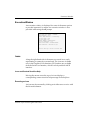
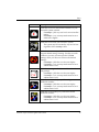
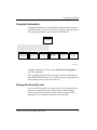
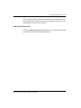
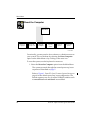
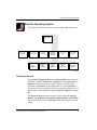
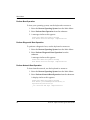
PowerPC™ Open Firmware
Quick Start Guide
Release 2.0
PPCOFWQSA/UG2
Notice
While reasonable efforts have been made to assure the accuracy of this document,
Motorola, Inc. assumes no liability resulting from any omissions in this document,
or from the use of the information obtained therein. Motorola reserves the right to
revise this document and to make changes from time to time in the content hereof
without obligation of Motorola to notify any person of such revision or changes.
No part of this material may be reproduced or copied in any tangible medium, or
stored in a retrieval system, or transmitted in any form, or by any means, radio,
electronic, mechanical, photocopying, recording or facsimile, or otherwise,
without the prior written permission of Motorola, Inc.
It is possible that this publication may contain reference to, or information about
Motorola products (machines and programs), programming, or services that are
not announced in your country. Such references or information must not be
construed to mean that Motorola intends to announce such Motorola products,
programming, or services in your country.
Restricted Rights Legend
If the documentation contained herein is supplied, directly or indirectly, to the U.S.
Government, the following notice shall apply unless otherwise agreed to in
writing by Motorola, Inc.
Use, duplication, or disclosure by the Government is subject to restrictions as set
forth in subparagraph (c)(1)(ii) of the Rights in Technical Data and Computer
Software clause at DFARS 252.227-7013.
Motorola, Inc.
Computer Group
2900 South Diablo Way
Tempe, Arizona 85282
Preface
The PowerPC Open Firmware Quick Start Guide provides the general information
and procedures required to test and initialize the system hardware, determine the
hardware conÞguration, and to boot the operating system.
Motorola® and the Motorola symbol are registered trademarks of Motorola, Inc.
PowerStackª is a trademark of Motorola, Inc.
PowerPCª and the PowerPC logo are trademarks of International Business Machines
Corporation.
AIX® and IBM® are registered trademarks of International Business Machines
Corporation.
Microsoft Windows® and MS-DOS® are registered trademarks of Microsoft Corporation.
The software and documentation are copyrighted materials. Making unauthorized
copies is prohibited by law. No part of the software or documentation may be
reproduced, transmitted, transcribed, stored in a retrieval system, or translated
into any language or computer language, in any form or by any means without the
prior written permission of Motorola, Inc.
DISCLAIMER OF WARRANTY
Unless otherwise provided by written agreement with Motorola, Inc., the software
and the documentation are provided on an Òas isÓ basis and without warranty.
This disclaimer of warranty is in lieu of all warranties whether express, implied, or
statutory, including implied warranties of merchantability or Þtness for any
particular purpose.
© Copyright Motorola, Inc.
All Rights Reserved
Printed in the United States of America
October 1996
Contents
General Information 1
Overview 1
Scope 1
PowerPC Implementation 1
Hardware Requirements 1
Display Device 2
Memory Requirements 2
EDO Memory ConÞguration 2
System Setup 3
System Power-Up 3
Initialization Process 4
PowerPC Open Firmware Console Detection 5
Keystroke and Mouse Introduction 6
Menu Level Keystrokes 6
Execution Window Keystrokes 6
Mouse Operation 7
Menu-Level Mouse 7
Execution Window Mouse 7
The Graphical User Interface 9
Motorola or OEM Logo 9
Time Clock 9
Submenu 10
Context Sensitive Help Text Window 10
Execution Window 11
Icons 11
Icons and Context Sensitive Help 11
Executing an Icon 11
Display and Security of Icons 12
Main Menu 14
Copyright Information 15
Change the Security Level 15
Menu- and Boot-Level Security 16
Display the Security Level 16
Set Novice User Level 17
Set Advanced User Level 17
Set Administrator Level 18
Change the Current Password 18
Help on Security Levels 19
Reset the Computer 20
Boot the Operating System 21
The Booting Process 21
Perform Boot Operation 22
Perform Diagnostic Boot Operation 22
Perform Network Boot Operation 22
Perform Auto-Scan Boot Operation 23
Help on Booting the Operating System 23
Advanced Options 24
Display the System Configuration 25
Display Hardware Devices Menu 29
Firmware Diagnostics 33
Configure Keyboard Options 36
Help on Advanced Options 37
Administrative Options 38
Invoke the Command Line Prompt 39
Set the Date and Time 40
Enable or Disable Security 42
Modify the Configuration Settings 43
Update Your Firmware 49
Help on Administrative Options 58
Overview
General Information
Overview
This guide introduces you to the basic features of the PowerPC
Open Firmware and the tasks you need to perform using the
Graphical User Interface.
The primary tasks of PowerPC Open Firmware are to test and
initialize the system hardware, determine the hardware
conÞguration, and boot the operating system.
Scope
The PowerPC Open Firmware Quick Start Guide quickly steps you
through the procedures for booting and resetting the system,
customizing the logo, displaying and modifying the conÞguration
variables, running the self tests, and updating the Þrmware ROM.
This guide does not provide conceptual or detailed technical
information.
PowerPC Implementation
The PowerPC implementation of Open Firmware is based on the
PowerPC Binding to Open Firmware.
Hardware Requirements
A Motorola PowerPC system. Currently, PowerPC Open
Firmware is supported on the PowerStackII Series E, Series EX,
Pro2000/200, Pro3000/200, Pro4000/166, Pro4000/200,
Net4000/166, Net4000/200 and the RISC PC and RISC PC Plus.
PowerPC Open Firmware Quick Start Guide
1
Memory Requirements
Display Device
For display on a graphics terminal, a VGA display and a
Þrmware-supported PCI graphics card are required. Please refer
to the PowerPC Open Firmware Supported PCI Cards Quick Reference
for a listing of supported devices.
For display on a serial terminal, an ANSI-compatible 80x24
terminal or terminal emulator is required.
Memory Requirements
The amount of memory in the system is dynamically identiÞed by
PowerPC Open Firmware and does not require user intervention.
Special modiÞcations are required only if EDO (Extended Data
Out) memory is used.
Refer to the System Installation Guide for details regarding the
physical memory requirements of the system.
EDO Memory Configuration
For systems that do not support EDO memory, the default state of
the edo-memory? variable is false and must always be false.
For systems supporting EDO memory, Pro2000/200 and
Pro3000/200, PowerPC Open Firmware must be conÞgured to use
the timing values for EDO memory. The default state of the edomemory? variable must be set to true.
To set the NVRAM variable, at the ok prompt type:
setenv edo-memory? true and press RETURN.
Reset the system to use the new value.
2
PowerPC Open Firmware Quick Start Guide
EDO Memory Configuration
System Setup
The PowerPC Open Firmware is installed by Motorola at the
factory when your PowerPC system or board is manufactured.
Refer to your PowerPC board or system installation manual and
verify that the necessary hardware preparation has been
properly completed.
System Power-Up
Refer to your PowerPC board or system installation manual for
steps on powering up your system.
PowerPC Open Firmware Quick Start Guide
3
Initialization Process
Initialization Process
The MPU, hardware, and Þrmware initialization process is
performed by the PowerPC Open Firmware power-up or system
reset. The Þrmware initializes the devices on the computer
motherboard in preparation for booting your operating system.
The Þrmware is shipped from the factory with an appropriate
set of defaults. In most cases there isnÕt a need to modify the
conÞgurations in the Þrmware prior to booting your operating
system.
This ßowchart shows the basic initialization process which
occurs during PowerPC system startup.
STARTUP
SYSTEM
INITIALIZATION
CONSOLE
DETECTION
RUN SELFTESTS
AUTOBOOT
OPERATING
SYSTEM OR
CLIENT
INTERFACE
11439.00 9605
Figure 1. PowerPC Open Firmware System Startup
4
PowerPC Open Firmware Quick Start Guide
EDO Memory Configuration
Your PowerPC Open Firmware has been conÞgured to
automatically initialize your system, detect your console (VGA or
serial), run system selftests, and autoboot your operating system.
If
Then
Your operating system has
already been installed on
your PowerPC system
The PowerPC Open Firmware automatically
detects the installed operating system and
autoboots it.
The operating system has
not been installed on your
PowerPC system
Refer to the installation instructions that came
with your operating system. You may be
instructed to interrupt the PowerPC Open
Firmware startup sequence so you can install the
operating system. This step would require you to
make a keystroke prior to the autoboot step that
occurs in the startup sequence.
PowerPC Open Firmware Console Detection
Typically, the console is either the combination of a
text/graphics display device (VGA type terminal) and a
keyboard or an ASCII terminal connected to a serial port.
This table shows how PowerPC Open Firmware determines
whether it should be displayed on the VGA terminal or the
serial port during the power-up/reset sequence.
KBD
Connected
Firmware Supported VGA
Device/Card Exists
Firmware is
Displayed On
yes
yes
VGA terminal
no
yes
Serial (COM1)
no
no
Serial (COM1)
yes
no
Serial (COM1)
The PCI video cards in the Òplug-inÓ slots are checked Þrst, and
then a check is made for an Òon-boardÓ video device. The slots
are checked from top to bottom.
PowerPC Open Firmware Quick Start Guide
5
Keystroke and Mouse Introduction
Keystroke and Mouse Introduction
Menu Level Keystrokes
The following keystrokes are used in the menu interface to easily
navigate through the task selection process:
Key Action
Description
<ENTER>
Executes the highlighted menu option. This may bring up
another submenu or start an execution window.
Up/Down
Arrow
Moves the highlight bar to the next or previous selection.
<ESC>
Closes the current submenu and returns you to the previous
menu
Execution Window Keystrokes
An execution window is created for some of the menu options to
provide input at the Command Line Interface (ok prompt) or to
display output.
6
Key Action
Description
Page Up/
Down
Moves the visible portion of the display up or down one page.
Up to 10 pages are available in an execution window.
Spacebar
Pauses or unpauses the output.
<ENTER>
Displays a single field.
<ESC >
Closes the execution window and returns control to the menu
which started it.
menu
<ENTER>
Returns from the ok prompt to the menu.
Right /Left
Arrow
Moves the cursor to the right or to the left.
PowerPC Open Firmware Quick Start Guide
Mouse Operation
Mouse Operation
PowerPC Open Firmware has two levels of mouse support.
❏
Menu level
❏
Execution window
Note that the mouse is not available at the Command Line Interface
(ok prompt). Mouse support requires a VGA display device.
Menu-Level Mouse
Moving the mouse over a menu or submenu item causes the menu
highlight bar to change position and help text to appear in the
context-sensitive help window at the bottom of the screen.
Action
Description
Right click
The right click functions the same as the <ESC> keystroke and the
minus button in the upper left corner of the menu window. Any of
these actions may be used to close down the current submenu
window.
Left click
To execute an icon or menu item with the mouse, either single or
double click on the icon or menu item. To close a submenu
window, click on the minus button in the upper left corner of the
menu window. Note that you cannot close the main menu
window.
Execution Window Mouse
Action
Description
Right click
The right click may be used to close down an execution window
when the message ÒPress the <ESC> key to return to the menuÓ is
displayed after execution.
PowerPC Open Firmware Quick Start Guide
7
Keystroke and Mouse Introduction
Note
8
Although icon context-sensitive help is available from
within an execution window, you cannot execute icons
in this window. You must return to the menu system in
order to execute an icon.
PowerPC Open Firmware Quick Start Guide
Motorola or OEM Logo
The Graphical User Interface
The Main Menu lists the major options that you most commonly
execute. Menu selection and execution is made by using the Up or
Down arrow keys and pressing ENTER, or by clicking on the
option with the left mouse button.
Time Clock
Logo
Dec 28, 1995 9:27 00 am
Main Menu
Selections
Display the Copyrights
Change the Security Level...
Reset the Computer
Boot an Operating System...
Advanced Options...
Administrative Options...
Icons
Context Sensitive Help Text Window
Figure 2. Main Menu Components
Motorola or OEM Logo
The upper left corner of the Main Menu displays an OEM logo. A
mouse click on the logo displays the copyrights. The Motorola logo
is the default.
Time Clock
The time clock feature displays the current date, time, and year in
your local time while you are navigating the menu. A mouse click
on the time clock display produces an execution window that
allows you to change the date and time. A security check is also run
to ensure that you have administrative privileges. When the system
is busy or executing a command, the message, ÒClock is
UnavailableÓ is displayed.
PowerPC Open Firmware Quick Start Guide
9
The Graphical User Interface
Submenu
This lower-level menu offers detailed options in the subject
category speciÞed by the parent menu. Submenus are displayed in
a cascading formation.
Dec 28, 1995 9:27 00 am
Submenu
Selections
Display the Copyrights
the Security
Change Display
the Security
Level...Level
Novice User Level
Reset theSet
Computer
Set Advanced
User Level
Boot an Operating
System...
SetOptions...
Administrator Level
Advanced
ChangeOptions...
the Current Password
Administrative
Help on Security Levels
Figure 3. Example of a Submenu
Context Sensitive Help Text Window
The context sensitive help text window at the bottom of the screen
displays additional information about the currently highlighted
menu selection. This window is updated as the cursor or mouse is
moved within a menu or submenu.
Context sensitive help is also displayed for each of the icons by
placing the mouse pointer over the top of the icon. Context sensitive
help is also displayed for the OEM logo, time window, and context
sensitive help window when the mouse pointer is placed over these
regions.
10
PowerPC Open Firmware Quick Start Guide
Execution Window
Execution Window
An execution window is displayed for some of the menu options
to provide input and/or output. An execution window is also
provided when using the ok prompt.
Board (PWA) Serial Number = “1954499”
Board Identifier = “bh “
Artwork (PWA) Identifier = “01-W3107f02g”
MPU Clock Speed = “100”
BUS Clock Speed = 067”
Ethernet Address = “08003E303433”
Local SCSI Identifier - “07”
System serial Number = “MOTRISC1954499”
System Identifier = “MOT RISC PC (e0)”
...
Press the <ESC> key to return to the main menu
Icons
Along the right-hand side of the menu are several icons, each
representing a commonly executed task. The icons are available
only in the Graphical User Interface (GUI) and are not available
from the Serial User Interface, which is strictly an 80x24 ASCII
interface.
Icons and Context Sensitive Help
Moving the mouse across the top of an icon displays a
corresponding context sensitive help message in the help box.
Executing an Icon
An icon may be executed by clicking on it either once or twice with
the left mouse button.
PowerPC Open Firmware Quick Start Guide
11
The Graphical User Interface
Display and Security of Icons
There is security attached to each of the icons in PowerPC Open
Firmware. Executing an icon is like executing a menu option, Þrst a
security check is done prior to actual execution of the item if
security? = true. There are eight icons, however, the number of icons
displayed on your VGA screen depend on your security settings in
the Þrmware. By default, your PowerPC system is shipped with
security? = false (the security system in the Þrmware is disabled).
The Graphical User Interface is conÞgured in the factory with
security?=false which displays only the Þrst four icons. It doesnÕt
matter what the NVRAM conÞguration variable security-mode is
in this case.
If security is desired and you wish to display all eight icons, you
must set security? = true and choose new passwords for each level
using the Change the Security Level menu option. Also, the
NVRAM conÞguration variable security-mode must be set to
administrator.
Icon
Description
Click this icon to boot an operating system or client
interface.
This option may be executed by any level of user
regardless of the security? value.
Click this icon to look at the computer system
components. A graphical display showing the
PowerPC processor type, memory size, and L2 cache
size will appear in the execution window. A list of
attached boot-related devices is also displayed.
If security? = false any user level can execute this
option.
If security? = true, security-mode must be set at
novice or higher
12
PowerPC Open Firmware Quick Start Guide
Icons
Icon
Description
Click this icon to run the extended selftests on your
PowerPC system or board.
If security? = false any user level can execute this
option.
If security? = true, security-mode must be set at
advanced or higher.
Click this icon to reset your PowerPC system.
This option may be executed by any level of user
regardless of the security? value.
Click this icon to reset your NVRAM variables to their
original default setting. Warning: Use this icon with
caution as you may lose user-speciÞc NVRAM
settings when you choose to return to the default
settings.
If security? = false this icon does not display.
If security? = true, security-mode must be set at
administrative level.
Click this icon to go to the Command Line Interface
(ok prompt).
If security? = false this icon does not display.
If security? = true, security-mode must be set at
administrative level.
Click this icon to modify any of the conÞguration
NVRAM variables.
If security? = false this icon does not display.
If security? = true, security-mode must be set at
administrative level.
Click this icon to modify any of the boot-related
NVRAM variables.
If security? = false this icon does not display.
If security? = true, security-mode must be set at
administrative level.
PowerPC Open Firmware Quick Start Guide
13
Main Menu
Main Menu
The PowerPC Open Firmware GUI is accessed after power-up or
restart if these conditions are true:
❏
The auto-boot is disabled auto-boot?=false
❏
You manually interrupt the auto-boot countdown
The intuitive GUI is designed to provide easy access to the most
commonly used Þrmware features, as shown below.
Main Menu
Display the
Copyrights
Change the
Security Level
Reset the
Computer
Boot an
Operating
System
Advanced
Options
Administrative
Options
11433.00 9605
14
PowerPC Open Firmware Quick Start Guide
Copyright Information
Copyright Information
Copyright information is automatically displayed during powerup and reset but can also be viewed by clicking on the logo area or
selecting the appropriate option from the Main Menu.
Main Menu
Display the
Copyrights
Change the
Security Level
Reset the
Computer
Boot an
Operating
System
Advanced
Options
Administrative
Options
11427.00 9605
Using the keyboard or mouse, select Display the Copyrights to
view the copyrights.
The copyrights remain on the screen for several seconds and are
then cleared. The Motorola, Inc. and the Firmworks copyrights are
always displayed and cannot be removed.
Change the Security Level
Access to the PowerPC Open Firmware GUI and Command Line
Interface is controlled by one of three security-mode settings,
Novice, Advanced, and Administrator. Each mode provides a
different level of available commands at the interface.
PowerPC Open Firmware Quick Start Guide
15
Main Menu
Menu- and Boot-Level Security
Each one of the three security levels requires a different password
that must be between one and eight characters long. In order to
access a particular security level, the user needs to login as that level
or higher. A submenu exists which allows users to login to different
levels and to change the password of the current security level.
The administrative-level boot-time options are explained in detail
in the PowerPC Open Firmware UserÕs Manual, Volume 1.
Main Menu
Display the
Copyrights
Change the
Security Level
Reset the
Computer
Boot an
Operating
System
Advanced
Options
Administrative
Options
Display the
Security
Level
Set Novice
User Level
Set
Advanced
User Level
Set
Administrator
Level
Change the
Current
Password
Help on
Security
Levels
11437.00 9605
Display the Security Level
This option gives you information on the current security mode
setting. Use the keyboard or mouse to:
1. Select Display the Security Level to see what the current
setting is.
16
PowerPC Open Firmware Quick Start Guide
Change the Security Level
2. Press <ESC> or click the right mouse button to return to the
previous menu.
Set Novice User Level
The Novice level allows you to redisplay copyright messages,
boot the operating system, and reset the computer. Use the
keyboard or mouse to:
1. Select the Set Novice User Level option from the Change
Security Level menu.
2. At the prompt, type in the Novice level password (provided
by your Administrator) and press ENTER.
A message appears confirming that the security level is set to
Novice.
3. Press <ESC> or click the right mouse button to return to the
previous menu.
Set Advanced User Level
In addition to performing the novice-level tasks, the Advanced
level allows you to run system diagnostics, reconÞgure the
keyboard, and display hardware and software conÞguration
information. Use the keyboard or mouse to:
1. Select the Set Advanced User Level option from the Change
Security Level menu.
2. At the system prompt type the required password (provided
by your Administrator) and press ENTER.
A message appears confirming that the security level is set to
Advanced.
3. Press <ESC> or click the right mouse button to return to the
previous menu.
PowerPC Open Firmware Quick Start Guide
17
Main Menu
Set Administrator Level
The Administrator level allows setting of date and time,
modiÞcation of conÞguration settings, updating the Þrmware
ROM, and invoking the Command Line Interface. Use the keyboard
or mouse to:
1. Select the Set Administrator Level option from the Change
Security Level menu.
2. At the prompt, type in the administrator password and press
ENTER.
A message appears confirming that the security level is set to
Administrator.
3. Press <ESC> or click the right mouse button to return to the
previous menu.
If you are logged in at the Administrative level, you may also
modify the security modes from the Command Line Interface. This
is discussed in detail in the PowerPC Open Firmware UserÕs Manual,
Volumes 1 and 2.
Change the Current Password
This option allows you to change the password for your current
level of security. For example, if you are a novice you can change the
novice password.
To change your password, use the keyboard or mouse to:
1. Select the Change the Current Password option on the
Change Security Level menu.
The system prompts you to type in a new password.
2. Type your new password and press ENTER, you are then
prompted to re-enter your password.
3. Retype the password for verification.
18
PowerPC Open Firmware Quick Start Guide
Change the Security Level
If the retyped password doesnÕt match the new password, an error
message displays and the old password remains in effect. See your
administrator if you receive an error.
Help on Security Levels
Select the Help on Security Levels option to access the online help
provided for each of the security selections.
PowerPC Open Firmware Quick Start Guide
19
Main Menu
Reset the Computer
Main Menu
Display the
Copyrights
Change the
Security Level
Reset the
Computer
Boot an
Operating
System
Advanced
Options
Administrative
Options
11435.00 9605
Occasionally, you may need to do a software or a hardware reset to
your system. This can be done by selecting the Reset Computer
option on the Main Menu or by clicking on the reset icon.
To reset the system, use the keyboard or mouse to:
1. Select the Reset the Computer option from the Main Menu.
The system proceeds through the normal power-up/reset
sequence as described on page 5.
Refer to Figure 1. PowerPC Open Firmware System Startup on
page 4 for the default power-up/reset conÞguration. The
default sequence can vary if certain NVRAM variables such
as run-self-test? and auto-boot? are modiÞed.
20
PowerPC Open Firmware Quick Start Guide
Boot the Operating System
Boot the Operating System
PowerPC Open Firmware allows easy booting at the menu level.
Main Menu
Display the
Copyrights
Change the
Security Level
Reset the
Computer
Boot an
Operating
System
Advanced
Options
Administrative
Options
Perform
Boot
Operation
Perform
Diagnostic
Boot
Operation
Perform
Network
Boot
Operation
Perform
AutoScan
Boot
Operation
Help Booting
Operating
System
11426.00 9605
The Booting Process
For the Boot, Diagnostic Boot and AutoScan Boot operations, the
NVRAM variables: boot-device, diag-device, and pboot-devicedefault are parsed from left to right. The boot operation then
performs an open-dev on each parsed device. If the open-dev is
successful, a boot is performed on the successfully opened device to
the Þlename in the NVRAM variable: boot-Þle, diag-Þle, or bootÞle.
The Network Boot operation creates a string using the net-cfgmethod, serveripaddr, clientipaddr, gatewayipaddr, and boot-Þle.
The process then invokes a boot net: command using the created
string.
PowerPC Open Firmware Quick Start Guide
21
Main Menu
Perform Boot Operation
To boot your operating system, use the keyboard or mouse to:
1. Select the Boot an Operating System from the Main Menu.
2. Select Perform Boot Operation from the submenu.
3. A message similar to this appears:
Please wait while the system is booting
Boot device: boot File and args: ˘srmp\carloss.elf
Perform Diagnostic Boot Operation
To perform a diagnostic boot, use the keyboard or mouse to:
1. Select the Boot an Operating System from the Main Menu.
2. Select Perform Diagnostic Boot Operation from the
submenu.
A message similar to this appears:
Please wait while the system is booting
Boot device: boot File and args: ˘srmp\carloss.elf
Perform Network Boot Operation
To boot from the network, use the keyboard or mouse to:
1. Select the Boot an Operating System from the Main Menu.
2. Select Perform Network Boot Operation from the submenu.
A display similar to this appears:
Please wait while the system is booting
Boot device: /pci/ethernet@e:144.191.24.252,˘sr
mp\carloss.elf,144.191.24.76,0
.0.0.0 boot File and args: ˘srmp\carloss.elf
/
22
PowerPC Open Firmware Quick Start Guide
Boot the Operating System
Perform Auto-Scan Boot Operation
To do an auto-scan boot, use the keyboard or mouse to:
1. Select the Boot an Operating System from the Main Menu.
2. Select Perform Auto-scan Boot Operation from the
submenu.
Trying...,
Trying...,
Trying...,
Trying...,
Failed
boot Failed
fdisk0 Failed
cdrom0 Failed
tape0 Can’t rewind tape
Trying..., enet0 Booting
Please wait while the system is booting
Boot device: /pci/ethernet@e:144.191.24.252,˘sr
mp\carloss.elf,144.191.24.76,0
.0.0.0 File and args: ˘srmp\carloss.elf
-
Help on Booting the Operating System
Selecting this menu option gives you general help on the boot
process for your operating system. See the documents that came
with your current operating system for further details.
PowerPC Open Firmware Quick Start Guide
23
Advanced Options
These options are for the person who needs to display system
information and run diagnostics. Select the Advanced Options
from the Main Menu. A submenu appears that offers several
options to choose from.
Main Menu
Display the
Copyrights
Change the
Security Level
Reset the
Computer
Boot an
Operating
System
Advanced
Options
Display
System
Configuration
Display
Hardware
Devices
Firmware
Diagnostics
Configure
Keyboard
Options
Administrative
Options
11425.00 9605
24
PowerPC Open Firmware Quick Start Guide
Advanced Options
Display the System Configuration
By selecting this option you are presented with a submenu offering
many selections that display important conÞguration information.
Main Menu
Advanced
Options
Display System
Configuration
Display Board
Configuration
Block
Display
Hardware
Devices
Display the
Device Tree
Firmware
Diagnostics
Display
NVRAM
Variables
Display the
Device
Aliases
Configure
Keyboard
Options
Help on
System
Configuration
11436.00 9605
To view the submenu, use the keyboard or mouse to:
1. Select the Advanced Options from the Main Menu.
2. Select the Display System Configuration option.
PowerPC Open Firmware Quick Start Guide
25
Display the Board ConÞguration Block
To view information about your PowerPC system or board, use the
keyboard or mouse to:
1. Select the Display Board Configuration Block option from
the Display System Configuration menu.
A display similar to the following appears:
Board (PWA) Serial Number = “MOT1954496 “
Board Identifier = “Blackhawk Ultra “
Artwork (PWA) Identifier = “01-W3107F02G “
MPU Clock Speed = “100”
BUS Clock Speed = “067”
Ethernet Address = “08003E30344B”
Local SCSI Identifier = “07”
System Serial Number = “MOT123 “
System Identifier = “RISC PC
License Identifier = “12345678”
2. Press <ESC> or click the right mouse button to return to the
previous menu.
The conÞguration information is conÞgured in the factory. There is
no need to modify these values unless the NVRAM gets corrupted.
Display the Device Tree
This option allows you to view the individual device tree nodes that
make up your system. Use the keyboard or mouse to:
1. Select the Display the Device Tree option from the Display
System ConÞguration menu.
2. Use the Page Up/Page Down keys or mouse to scroll the list
of device tree nodes, or press any key to halt the device tree
display.
A display similar to the following appears:
/PowerPC,603
/Planar-ID
/abort-sw
/led@800008c0
/pci
26
PowerPC Open Firmware Quick Start Guide
Advanced Options
/mmu
/memory@0
/aliases
/menu./packages
/pci/DEC,ethernet@e
/pci/scsi@c
Press <ESC> or click the right mouse button to return to the
previous menu.
Display the NVRAM Variables
To display the variable names, values, and default values, use the
keyboard or mouse key to:
1. Select the Display the NVRAM Variables option from the
Display System ConÞguration menu.
The screen displays the current NVRAM information.
Variable Name
Value
Default Value
mot-oem-logo?
24-hour-time?
concurrent-mode?
concurrent-device
debug-device com1
menu?
serial-mouse
pci-probe-list
.
.
.
true
false
false
com1
screen
false
true
false
false
com1
screen
true
10,11,12,13,d,c,e,f
0,11,12,13,d,c,e,f
2. Press <ESC> or click the right mouse button to return to the
previous menu.
Note
To change a value, you must be logged in as an
Administrative user. The Edit Configuration Variables
icon or menu option can be used to modify the
Configuration NVRAM variables. The Edit Boot
Variable icon or menu option can be used to modify the
boot-related NVRAM variables.
PowerPC Open Firmware Quick Start Guide
27
Display the Device Aliases
The device aliases provide a shorthand version of a device path,
that makes it easier to access or refer to the devices on your system.
1. Select the Display the Device Aliases option from the
Display System ConÞguration menu.
The screen displays the current Device Aliases information.
screen
a
ntdisk
com3
com4
disk
cdrom
disk2
disk1
disk0
scsi
.
.
/pci/viper@12
/floppy
/pci/scsi@c/disk@0,0:\veneer.exe
/pci/isa/85230@i840:A
/pci/isa/85230@i840:B
/pci/scsi@c/disk@0,0:1
/pci/scsi@c/disk@5,0
/pci/scsi@c/disk@2,0:1
/pci/scsi@c/disk@1,0:1
/pci/scsi@c/disk@0,0:1
/pci/scsi@c
.
2. Press <ESC> or click the right mouse button to return to the
previous menu.
Help on System ConÞguration
Choose this option for descriptions and explanations of each
selection under the Display System Configuration menu option.
28
PowerPC Open Firmware Quick Start Guide
Advanced Options
Display Hardware Devices Menu
Select this option to check your hardware version, view the
contents of your ßoppy disk, and search the SCSI bus for devices.
Main Menu
Advanced
Options
Display
Hardware
Devices
Display System
Configuration
Display
Version
Information
Display
Extended
Version
Information
Display
Floppy Disk
Contents
Configure
Keyboard
Options
Firmware
Diagnostics
Search
SCSI Bus
for Device
Help on
Hardware
Devices
11431.00 9605
Display the Hardware Version Information
To see what version hardware your system is currently running, use
the keyboard or mouse to:
1. Select the Display Hardware Devices option.
2. Select the Display Hardware Version Information.
PowerPC Open Firmware Quick Start Guide
29
The screen displays the current version information similar to the
following.
...
Open Firmware Revision ID.......................1.0
Open Firmware Revision...Date.Tues Jan 30 14:46:31 MST 1996
CPU Type................................PowerPC,604
MicroProcessor Internal Clock Speed (MHZ).......100
Local Memory Size...........................4000000 (64MB)
...
3. Press <ESC> or click the right mouse button to return to the
previous menu.
Display the Extended Hardware Version Information
With this option you receive the same information that Display the
Hardware Version Information provides, but also additional
information on PCI class and subclass, and register content. Using
the keyboard or mouse:
1. Select the Display Hardware Devices option.
2. Select the Display Extended Hardware Version
Information.
A display similar to the following appears:
...
Open Firmware Revision ID.......................1.0
Open Firmware Revision...Date.Tues Jan 30 14:46:31 MST 1996
CPU Type................................PowerPC,604
MicroProcessor Internal Clock Speed (MHZ).......100
Local Memory Size...........................4000000 (64MB)
...
30
PowerPC Open Firmware Quick Start Guide
Advanced Options
0 01 00 06 01 80 20 24 00 00 06 00 00 00PCI Bus Bridge Device Registers
Base+$0000 57 10 01 00 06 01 80 20 24 00 00 06 00 00 00 00
Base+$0010 00 00 00 00 00 00 00 00 00 00 00 00 00 00 00 00
Base+$0020 00 00 00 00 00 00 00 00 00 00 00 00 00 00 00 00
.
.
.
/pci/cirrus@f
Device ID/Revision . . . . . . . . . . . . . . =a81013/8e
Class: Display Controller Subclass:VGA-compatible Controller
Base+$0000 13 10 Base+$0010 00 00 00 02 00 00 00 00 00 00 00 00 00 00
00 00
Base+$0020 00 00 00 00 00 00 00 00 00 00 00 00 00 00 00 00
Base+$0030 00 00 00 03 00 00 00 00 00 00 00 00 0b 01 00 00
...
3. Press <ESC> or click the right mouse button to return to the
previous menu.
Display the Floppy Disk Contents
To view a listing of directories and Þles resident on your ßoppy
drive, use the keyboard or mouse to:
1. Select the Display Hardware Devices.
2. Select the Display the Floppy Disk Contents.
The screen displays the ßoppy disk information.
----rwxrwxrwx 32 12/05/95 14:30:24 file1
----rwxrwxrwx 32 12/05/95 14:30:54 file2
----rwxrwxrwx 32 12/05/95 14:31:30 file3
3. Press <ESC> or click the right mouse button to return to the
previous menu.
Search the SCSI Bus for Devices
To view the SCSI devices connected to your system, use the
keyboard or mouse to:
1. Select the Display Hardware Devices option.
2. Select the Search the SCSI Bus for Devices.
PowerPC Open Firmware Quick Start Guide
31
The screen displays the current device information.
/pci/scsi@c
Target 0
Unit 0 Disk SEAGATE ST31230W 0465
Target 5
Unit 0 Removable Read Only device TOSHIBA CD-ROM XM-4101TA1084
3. Press <ESC> or click the right mouse button to return to the
previous menu.
Help on Hardware Devices
Selecting the Help on Hardware Devices provides you with further
detail and usage tips for the Display Hardware Devices options.
32
PowerPC Open Firmware Quick Start Guide
Advanced Options
Firmware Diagnostics
PowerPC Open Firmware provides several built-in diagnostics that
you can use to verify the correct operation of various aspects of the
board operation.
Main Menu
Advanced
Options
Display System
Configuration
Display
Cumulative
Test Results
Display
Hardware
Devices
Firmware
Diagnostics
Display
Diagnostic
Output Buffer
Run Full
Diagnostics
Configure
Keyboard
Options
Help on
Firmware
Diagnostics
11430.00 9605
Display Cumulative Test Results
Select this option to display a summary of the test results since the
last reset or power-up. Using the keyboard or mouse:
1. Select Display Cumulative Test Results from the Firmware
Diagnostics menu.
PowerPC Open Firmware Quick Start Guide
33
A display similar to the one below appears:
Total Tests Run: 18
Total Passed: 18
Total Failed: 0
2. Press <ESC> or click the right mouse button to return to the
previous menu.
Display the Diagnostic Output Buffer
This display is a cumulative log of ALL tests which have been run
since the last reset/power-up.
For example, if the Run the Full Diagnostics option has been run
twice since the last rest or power-up, then two sets of test results are
included in the diagnostics buffer.
If no diagnostics have been run since the last reset or power-up,
then a dialog box displays the following message:
The diagnostic output buffer is empty.
To view the test results, use the keyboard or mouse to:
1. Select Display the Diagnostic Output Buffer from the
Firmware Diagnostics menu.
A screen similar to this one is displayed:
Testing
Testing
Testing
Testing
Testing
Testing
Testing
Testing
Testing
/memory@0
/pci/scsi@c
/pci/viper@12
/pci/isa@b/floppy@i3f0
/pci/isa@b/lpt@i3bc
/pci/isa@b/com@i2f8
/pci/isa@b/com@i3f8
/pci/isa@b/nvram@i74
/pci/isa@b/rtc@i74
2. Press <ESC> or click the right mouse button to return to the
previous menu.
34
PowerPC Open Firmware Quick Start Guide
Advanced Options
Run the Full Diagnostics
These onboard diagnostic test routines check devices such as the
network controller, the ßoppy disk system, memory, PCI cards,
SCSI devices and the system clock.
To run the diagnostic tests, use the keyboard or mouse to:
1. Select Run the Full Diagnostics from the Firmware
Diagnostics menu.
A screen similar to this one is displayed:
Testing
Testing
Testing
Testing
Testing
Testing
Testing
Testing
Testing
/memory@0
/pci/scsi@c
/pci/viper@12
/pci/isa@b/floppy@i3f0
/pci/isa@b/lpt@i3bc
/pci/isa@b/com@i2f8
/pci/isa@b/com@i3f8
/pci/isa@b/nvram@i74
/pci/isa@b/rtc@i74
All of the device selftests passed, since no error messages were
displayed.
2. Press <ESC> or click the right mouse button to return to the
previous menu.
Help on Firmware Diagnostics
Selecting the Help on Firmware Diagnostics option provides
descriptions on each of the selections for running the PowerPC
Open Firmware diagnostics.
PowerPC Open Firmware Quick Start Guide
35
Configure Keyboard Options
PowerPC Open Firmware provides support for the United States
and some European style keyboards.
Main Menu
Advanced
Options
Display System
Configuration
Display
Hardware
Devices
Configure
Keyboard
Options
Firmware
Diagnostics
N-101 (EN)
Belgian
Danish
French
.
.
.
Norwegian
Portuguese
Spanish
UK
Help
Configuring
Keyboard
11562.00 9609
To modify the international keyboard, use the keyboard or mouse
to:
1. Select Advanced Options.
2. Select the Configure Keyboard Options.
A submenu displays listing the supported keyboard styles.
36
PowerPC Open Firmware Quick Start Guide
Advanced Options
3. Using the Up/Down arrow keys or the mouse, select the
language that you require.
That countryÕs keyboard is immediately activated and remains as
the set variable whenever the system is powered up.
Help on Advanced Options
Select this option to get more detail on system configuration,
hardware devices, running diagnostics, and keyboard
configurations.
PowerPC Open Firmware Quick Start Guide
37
Administrative Options
The Administrative Options selection is for the user who is
responsible for setting the date and time, modifying the system,
and updating the Þrmware.
Main Menu
Display the
Copyrights
Change the
Security Level
Reset the
Computer
Boot an
Operating
System
Advanced
Options
Administrative
Options
Invoke
Command
Line Prompt
Set the
Date & Time
Enable or
Disable
Security
Modify
Configuration
Settings
Update the
Firmware
Help on
Administrative
Options
11424.00 9605
38
PowerPC Open Firmware Quick Start Guide
Administrative Options
Invoke the Command Line Prompt
The Command Line Prompt (ok prompt) is an interactive
command interpreter that gives you access to an extensive set of
functions for hardware and software development, fault isolation,
and debugging.
Main Menu
Administrative
Options
Invoke
Command
Line Prompt
Set the
Date & Time
Enable or
Disable
Security
Modify
Configuration
Settings
Update the
Firmware
Help on
Administrative
Options
11434.00 9605
To access the Command Line Prompt, use the keyboard or mouse
to:
1. Select the Invoke Command Line Prompt option from the
Administrative Options menu.
2. An execution screen similar to this displays:
Type ‘menu’ to return to the menu.
ok
3. When you have finished using the Command Line Interface,
type menu and press ENTER to go back to the
Administrative Options main menu.
PowerPC Open Firmware Quick Start Guide
39
Set the Date and Time
Selecting Set the Date and Time results in a series of prompts that
help you set the systemÕs date and time. The default format for the
time portion of the display is in AM/PM style. The values you enter
will be in local 24-hour-time format.
Main Menu
Administrative
Options
Invoke
Command
Line Prompt
Enable or
Disable
Security
Set the
Date & Time
Modify
Configuration
Settings
Update the
Firmware
Help on
Administrative
Options
11429.00 9605
To set your current date and time, use the keyboard or mouse to:
1. Select Administrative Options from the Main Menu.
2. Select the Set the Date and Time option from the submenu.
When you select the Set the Date and Time option, the
display is cleared and the currently set date and local time are
displayed.
A series of prompts for setting the date appear sequentially as
you provide the information.
Enter
Enter
Enter
Enter
Enter
40
the
the
the
the
the
year (xxxx)
month (1-12)
day (1-30)
hour (0-23)
minute (0-59):
PowerPC Open Firmware Quick Start Guide
Administrative Options
3. Type in the current year, month, day, hour, and minute as
prompted and press ENTER.
If you enter a value outside of the range it is discarded and
you are prompted to enter the value again.
After entering the values, a message displays showing the
date and time which you entered and you are asked if it is
correct.
4. Respond with a Y or N and press ENTER or press the <ESC>
key to go to the previous menu.
Note
The time is changed only if you answer yes (Y). If you
answer no (N), the new date and time is discarded and
the message ÒUpdate AbortedÓ is displayed. Typing q
or Q in response to the date and time prompts also
aborts the update.
Modifying the Time Display
The default format for the time portion of the display is in AM/PM
style. PowerPC Open Firmware provides the option to change the
time display to 24-hour time format. To do this create the NVRAM
variable 24-hour-time? and set its value to true. If the variable
24-hour-time? is false or nonexistent, the time is displayed in
AM/PM style.
PowerPC Open Firmware Quick Start Guide
41
Enable or Disable Security
Choosing this option allows the administrator to enable or disable
security.
Main Menu
Administrative
Options
Invoke
Command
Line Prompt
Set the
Date & Time
Enable or
Disable
Security
Modify
Configuration
Settings
Update the
Firmware
Help on
Administrative
Options
11440.00 9605
Using the keyboard or mouse:
1. Select the Enable or Disable Security option from the
Administrative Options menu.
A dialog box is displayed with the message:
Would you like to enable security?
2. Respond with a Y or N and press ENTER, or click the desired
response with the mouse.
Choosing Y enables the security system in the firmware
(security? = true). Choosing N disables the security system in
the firmware (security?= false).
42
PowerPC Open Firmware Quick Start Guide
Administrative Options
Modify the Configuration Settings
System configuration variables are stored in the system NVRAM.
These variables determine the start-up machine configuration and
related communication characteristics. You can modify the values
of the configuration variables and any changes you make remain in
effect even after a power cycle. Configuration variables should be
adjusted cautiously.
Main Menu
Administrative
Options
Invoke
Command
Line Prompt
Set the
Date & Time
Edit
Configuration
Variables
Edit Boot
Variables
Enable or
Disable
Security
Modify
Configuration
Settings
Format
Hard Drive
Update the
Firmware
Restore
Default
Environment
Settings
Help on
Administrative
Options
Help on
Configuration
Settings
11492.00 9607
Using the keyboard or mouse:
1. Select Administrative Options from the Main Menu.
2. Select Modify Configuration Settings menu option.
A submenu with five selections is displayed.
PowerPC Open Firmware Quick Start Guide
43
Edit the ConÞguration Variables
Using the keyboard or mouse:
1. Select the Edit the Configuration Variables option.
The NVRAM variables are presented one-at-a-time, similar to
this example:
Press <ENTER> to use the existing value.
Type =<ENTER> to use the default value.
Type .<ENTER> to exit and save changes.
Variable Name
Current Value Default Value
mot-oem-logo?
24-hour-time?
concurrent-mode?
concurrent-device
debug-device
menu?
true
false
false
com1
screen
false
true
false
false
com1
screen
true
New Value:
The responses are:
Press <ENTER> to accept the existing NVRAM variable
Press = <ENTER> to set the NVRAM variable to the default
value
Press . <ENTER> to exit, save, and return to the menu
Type newvalue <ENTER> to replace the existing NVRAM
value
2. To return to the previous menu at any time:
Press q <ENTER> to exit
All changes are dynamic and immediately saved to NVRAM.
You may rerun this option or reset the default values if you
want to restore a variable that was accidentally modified.
44
PowerPC Open Firmware Quick Start Guide
Administrative Options
3. Press the <ESC> key or click the right mouse button to return
to the previous menu.
Refer to the PowerPC Open Firmware UserÕs Manual, Volume 2
for further information on editing these variables.
Edit the Boot Variables
This option allows you to interactively modify the NVRAM boot
related variables.
1. Select the Edit the Boot Variables option.
The ok prompt appears where you can use the Command
Line Interface to edit and change the variables.
As each line is displayed, you may skip to the next variable
by pressing the ENTER key. To exit, type:
. <ENTER> or
q <ENTER>
2. To set a variable to its default condition, type:
= <ENTER>
In cases without a default condition, this erases that
particular variable.
3. To change a variable to a new, nondefault condition, type the
new contents at the prompt and press ENTER.
All changes made are immediately saved to NVRAM. You
may rerun this option or reset the default values if you would
like to restore something that was accidentally modified.
4. Press the <ESC> key or click the right mouse button to return
to the previous menu.
PowerPC Open Firmware Quick Start Guide
45
Format the Hard Drive
Choosing this option allows you to format a SCSI hard drive and
place a single, FAT file system partition on the drive.
1. Select the Format the Hard Drive option.
The available SCSI devices are displayed for you to select
from, similar to this example:
Scanning for devices, please wait.
/pci/scsi@c
a) target 0 Unit 0 Disk SEAGATE ST32430W 0660
/pci/scsi@11
/pci/pci@13/scsi@6
b) target 0 Unit
0 Disk SEAGATE
ST12400N ST324300456
2. You are prompted to select the drive you want to format.
Enter the corresponding letter of the drive and press ENTER,
or press q to quit.
Enter the letter of the drive you wish to format. (q)uit
b (b = drive selected)
3. The following prompt appears. If you wish to continue with
the format option, enter y.
Initializing device, please wait.
Should you decide to format the disk, a destructive low-level
format will be performed and a FAT file partition placed on
the disk. This partition will be the only defined partition on
the disk.
Do you want to continue? (y/n)
If you wish to abort the procedure, enter n and press <ESC>
to return to the previous menu. Otherwise, enter y to
continue.
46
PowerPC Open Firmware Quick Start Guide
Administrative Options
4. You are then asked to enter the size of the FAT partition.
Enter FAT partition size in MB. (default = 20 = enter)
Partition Region
Boot
Format
1
Primary Yes
Size (MB)
FAT-16 20
done
Restore Default Environment Settings
Choosing this option forces the default NVRAM configuration
variable settings.
Warning: Use this icon with caution as you may lose user-speciÞc
NVRAM settings when you choose to return to the default settings.
Using the keyboard or mouse:
1. Select the Restore Default Environment Settings option.
A pop-up window displays and you are prompted to set the
NVRAM variables. If you decide not to change the variables,
return to the submenu by pressing the <ESC> key. Refer to
the NVRAM edit options above for further NVRAM editing
information.
2. A dialog box is displayed which asks:
Are you sure you want to reset the NVRAM variables?
3. Enter Y or N at the keyboard or click the desired button.
Choosing the N button aborts the NVRAM to the defaults
options and automatically returns you to the menu.
Choosing the Y button sets the NVRAM variables to their
defaults. Another dialog box displays which asks:
Do you want to reset the local system (CPU)?
4. Enter a Y or N or click the desired response with the mouse.
PowerPC Open Firmware Quick Start Guide
47
Choosing Y resets the system and settings take affect
immediately. Choosing N does not reset the system which
defers the effect of the defaults until the next power-up or
reset. Select N to return to the menu.
Help on ConÞguration Settings
Select this option for further details on default values and
modifying the conÞguration variables.
48
PowerPC Open Firmware Quick Start Guide
Update Your Firmware
If your system is currently running the PPC1Bug Þrmware and you
are updating to the new PowerPC Open Firmware, please read the
following information.
Main Menu
Administrative
Options
Invoke
Command
Line Prompt
Set the
Date & Time
Enable or
Disable
Security
Modify
Configuration
Settings
Update the
Firmware
Help on
Administrative
Options
Save the
Existing
ROM
Update the
Firmware
ROM
Replace the
Logo
Bitmap
Help on
Update
Commands
11438.00 9605
Using the keyboard or mouse:
1. Select the Administrative Options from the Main Menu.
2. Select Update the Firmware.
Save the Existing ROM
You can save the current ROM resident Þrmware out to disk so it
can be reinstalled at a later date.
Getting Started with PowerPC Open Firmware
49
1. Using the keyboard or mouse, select the Save the Existing
ROM option and respond to the prompt by removing all
tapes and disks from the system.
Disks and tapes should be removed from the system since the
ROM image is saved to the first formatted disk or tape found.
2. Insert a DOS formatted disk or tape on which to store the
saved ROM image.
Note
No special formatting of the disk is required if a
preformatted (IBM format) high density floppy disk is
used. Otherwise, format the floppy disk using a FAT
(File Allocation Table) format, such as AIXÕs dosformat
command.
3. If the disk needs to be formatted at this time, enter an N to
return to the Update The Firmware menu.
Since PowerPC Open Firmware does not provide formatting
capabilities, an operating system that supports DOS
formatting needs to be booted, or you may format at another
system that provides the DOS format capability. Format the
disk and restart the Save the Existing ROM process.
4. Insert the formatted disk or tape and respond by answering
Y to the prompt.
If the firmware is running on a MVME2600/3600 Series
product, continue with step 5. For all other products skip to
step 6.
5. Firmware running on a MVME2600/3600 Series product
displays the following prompt:
Select Flash Bank:
(A) Bank A
(B) Bank B
Bank? (A/B)
Make your selection by entering either A or B.
50
Getting Started with PowerPC Open Firmware
Note
Because MVME2600/3600 Series products provide two
distinct flash memory banks, selection of a bank is
required. Only the first megabyte is saved to disk due
to the limitations of the floppy disk medium.
6. The following prompt appears next:
Firmware Selection:
(B)PPC1BUG
(O)Open Firmware
Which Firmware Do You Currently Have in ROM? (B/O)
7. Select the firmware type that is currently in ROM: PPC1BUG
or Open Firmware.
With the selection entered, a probe for a formatted floppy
disk is performed. If no floppy disk is found or if a floppy
drive is not attached, the following prompt appears:
No Floppy Drive/Disk Found
Search SCSI Bus? (Y/N)
8. Search the SCSI bus by entering Y to the query. Enter N to
bypass a SCSI bus search and return to the main Update The
Firmware menu.
9. Select Y to search the SCSI bus for devices with removable,
writable media installed. It chooses the first one found as the
selected device. If the SCSI search mode is inadvertently
entered, simply press the escape key, <ESC>, to break out
and return to the Update The Firmware menu.
Getting Started with PowerPC Open Firmware
51
When a formatted disk or tape is located, the following
prompt appears:
Formatted Disk/Tape Found At /pci/ccc/ddd
Save To This Device? (Y/N)
10. Type a Y if you desire to save the ROM image at this time to
the indicated device and disk or tape. If you type an N, the
save process halts and returns you to the Update The
Firmware menu. (Note: ccc = controller string, ddd = device
string)
Saving the ROM image takes approximately 1 to 2 minutes.
Update the Firmware ROM
Updating to PowerPC Open Firmware can be performed from
either of the following Þrmware images loaded in ROM and
running in the system:
❏
PPC1BUG (to update to PowerPC Open Firmware)
❏
PowerPC Open Firmware (to update to the current revision)
To Open Firmware Starting From PPC1BUG
1. Go to the PPC1-Bug> prompt.
2. Perform a pboot from the PPC1Bug command line and select
the bootable disk or tape as follows.
PPC1-Bug>
pboot 1,0
This initiates a pboot from controller 1 (typically the floppy
disk controller) device 0. See the pboot and ioi commands in
the PPCBUG Firmware Package UserÕs Manual for further
details.
Executing the pboot command loads a RAM image of
PowerPC Open Firmware and passes control to it. The
contents of ROM have not yet been altered.
3. Continue with the steps in the following section to update the
firmware image in ROM.
52
Getting Started with PowerPC Open Firmware
To PowerPC Open Firmware From Open Firmware
Follow these steps to update to PowerPC Open Firmware from an
earlier version of Open Firmware.
1. Using the keyboard or mouse, enter the Administrative
Options menu.
2. Select Update The Firmware option.
3. Select Update The Firmware ROM option.
The following prompt appears:
Insert Bootable Disk or Tape with Firmware Upgrade
Proceed? (Y/N)
4. Insert the bootable floppy disk or tape into the appropriate
drive and enter a Y to continue the update process. Enter an
N to return to the Update the Firmware menu.
5. If you enter a Y and the firmware is running on a
MVME2600/3600 Series product, continue with step 6. For all
other products skip to step 7.
6. Firmware running on a MVME2600/3600 Series product
displays the following prompt:
Select Flash Bank:
(A) Bank A
(B) Bank B
Bank? (A/B)
Make your selection by entering either A or B.
Note
Because MVME2600/3600 Series products provide two
distinct flash memory banks, selection of a bank is
required. Only the first megabyte is updated to flash
memory due to the limitations of the floppy disk
medium.
Getting Started with PowerPC Open Firmware
53
7. If you responded with a Y in step 4, a probe for a bootable
floppy disk is performed. If no floppy disk is present or if no
floppy drive is attached, the following prompt appears:
No Floppy Drive/Disk Found
Search SCSI Bus? (Y/N)
8. To bypass a SCSI bus search and return to the main Update
The Firmware menu, enter N and press <ENTER>.
9. To search the SCSI Bus, enter Y and press <ENTER>.
The SCSI bus search looks for devices with removable,
writable media installed and chooses the first one found as
the selected device. If the SCSI search mode is inadvertently
entered, press the escape key, <ESC> to break out and return
to the main Update The Firmware menu.
Once a disk or tape containing the bootable image is located,
the new firmware image is loaded into RAM and verified.
During this process the following messages are displayed:
Loading From Floppy Drive /pci/ccc/ddd (or “Loading From
SCSI Device /pci/ccc/ddd”)
Validating Firmware Image ...
After validation is complete, the results are displayed as one
of the following:
Not A Valid Load Image
10. Enter an N to bypass the process and return to the Update
the Firmware menu.
If the image is not valid, the update process is terminated.
11. Press the <ESC> key or click the right mouse button to return
to the main Update the Firmware menu.
or
Ready To Update ROM Update Process Can Take Several Minutes
To Complete
Proceed? (Y/N)
54
Getting Started with PowerPC Open Firmware
Note
If the image is valid and you wish to proceed, you must
remove the floppy disk from the disk drive before
selecting Y.
12. Enter a Y to load the image into ROM and overwrite the
existing firmware. Once the ROM is updated, the system is
automatically reset. During the process the following is
displayed:
Updating ROM
Erasing ...
Programming ...
Verifying ...
This update process can take up to several minutes to
complete. If after three minutes, the system has not rebooted,
the ROM(s) have been corrupted and need to be replaced.
Getting Started with PowerPC Open Firmware
55
Replace the Logo Bitmap
You may flash an OEM logo bitmap into ROM in order to
supersede the default Motorola logo bitmap. The NVRAM variable
mot-oem-logo? is used to choose between the default logo and the
OEM logo. This variable defaults to false.
The bitmap Þle must be in the standard (uncompressed) 256-color
Microsoft Windows .bmp format. The image should be 300 pixels
wide by 75 pixels high. If this area is too large, fill in the unused
pixels with the background color (index $13).
Choose this option to add a user-deÞned logo to PowerPC Open
Firmware.
1. Have a floppy disk ready that contains the new logo bitmap
file. The file must be properly formatted and stored on a DOSformatted floppy disk with the filename oemlogo.bmp.
2. Using the keyboard or mouse, select the Replace the Logo
Bitmap from the Update the Firmware menu.
3. The following prompt is displayed:
Insert Floppy Disk Containing New Logo Bitmap
Proceed? (Y/N)
4. To proceed, insert the floppy disk containing the new logo
into the floppy drive, enter Y and press <ENTER>, or enter N
to bypass the process and return to the Update the Firmware
menu.
5. If you enter a Y and the firmware is running on a
MVME2600/3600 Series product, continue with step 6. For all
other products skip to step 7.
6. Firmware running on a MVME2600/3600 Series product
displays the following prompt:
Select Flash Bank:
(A) Bank A
(B) Bank B
Bank? (A/B)
56
Getting Started with PowerPC Open Firmware
Make your selection by entering either A or B.
Note
Because MVME2600/3600 Series products provide two
distinct flash memory banks, selection of a bank is
required.
7. Enter Y and press <ENTER> to proceed with the
replacement. A search for the file oemlogo.bmp is
performed. When the file is found, the following prompt is
displayed:
Update the OEM Bitmap Logo in ROM Using This File? (Y/N)
8. If no floppy disk is present or if a floppy drive is not attached
the following prompt is displayed and the bitmap update
process is terminated.
No Floppy Drive and/or Disk Found
Press <ESC> to return to the Update the Firmware menu.
9. Enter Y to store the new image into ROM. During this process
the following is displayed:
Loading Image Into ROM ...
Erasing ...
Programming ...
Verifying ...
Once the ROM is updated the following prompt is displayed:
New Logo Added
Set mot-oem-logo? Flag (This Will Enable New Logo)?
(Y/N)
10. Enter Y and press <ENTER> to enable the new bitmap logo.
11. Enter N and press <ENTER> to select the default Motorola
logo.
Getting Started with PowerPC Open Firmware
57
Color Indexes
The following VGA standard color indexes are available for use in
the bitmap:
$00
dark black
$08 light black (light gray)
$01
dark red
$09 light red
$02
dark green
$0A light green
$03
dark yellow
$0B light yellow
$04
dark blue
$0C light blue
$05
dark violet
$0D light violet
$06
dark cyan
$0E light cyan
$07
dark white (dark gray)
$0F light white
The following extended color indexes are also available. All other
color indexes are reserved by Motorola.
$10
dark border black (0,0,0)
$11
medium border gray ($5A,$5A,$5A)
$12
light border gray ($87,$87,$87)
$13
background gray ($B3,$B3,$B3)
Help Option for Updating Your Firmware
To view online help for each of the Update the Firmware options,
select Help on Update Commands and press ENTER.
Help on Administrative Options
Select this option to get more detail on using the Command Line
Interface, setting the date and time, enabling security, modifying
the configuration settings, and updating your firmware.
58
Getting Started with PowerPC Open Firmware