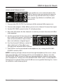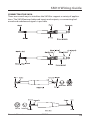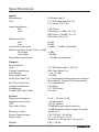
1
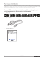
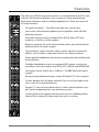
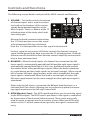
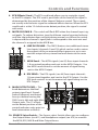
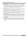
10-Channel Rack Mount Line Mixer
Owner’s Manual
www.samsontech.com
Important Safety Information
AVIS
RISQUE DE CHOC ÉLECTRONIQUE NE PAS OUVRIR
CAUTION: TO REDUCE THE RISK OF ELECTRIC SHOCK, DO NOT
REMOVE COVER (OR BACK). NO USER-SERVICEABLE PARTS
INSIDE. REFER SERVICING TO QUALIFIED SERVICE PERSONNEL.
This lightning flash with arrowhead symbol within an equilateral triangle is
intended to alert the user to the presence of non-insulated “dangerous voltage” within the product’s enclosure that may be of sufficient magnitude to
constitute a risk of electric shock.
The exclamation point within an equilateral triangle is intended to alert the
user to the presence of important operating and maintenance instructions
in the literature accompanying the appliance.
If you want to dispose this product, do not mix it with general household waste. There is a
separate collection system for used electronic products in accordance with legislation that
requires proper treatment, recovery and recycling.
Private household in the 25 member states of the EU, in Switzerland and Norway may return their used
electronic products free of charge to designated collection facilities or to a retailer (if you purchase a similar
new one).
For Countries not mentioned above, please contact your local authorities for a correct method of disposal.
By doing so you will ensure that your disposed product undergoes the necessary treatment, recovery and
recycling and thus prevent potential negative effects on the environment and human health.
Important Safety Information
1.
Read these instructions.
2.
Keep these instructions.
3.
Heed all warnings.
4.
Follow all instructions.
5.
This apparatus shall not be exposed
to dripping or splashing liquid and
no object filled with liquid, such as
a vase, should be placed on the apparatus.
6.
Clean only with a dry cloth.
7.
Do not block any of the ventilation
openings. Install in accordance with
the manufacturer's instructions.
8.
9.
Do not install near any heat sources
such as radiators, heat registers,
stoves, or other apparatuses (including amplifiers) that produce heat.
Only use attachments/accessories
specified by the manufacturer.
10. Unplug this apparatus during lightning storms or when not in use for
long periods of time.
11. Do not override the intended purpose of the polarized or groundingtype plug. A polarized plug has
two blades, with one wider than
the other. A grounding-type plug
has two blades and a third grounding prong. The wide blade, or third
prong, is provided for your safety.
If the provided plug does not fit
your outlet, consult an electrician to
replace the obsolete outlet.
12. Protect the power cord from being
walked on or pinched, particularly at
the prongs, convenience receptacles,
the point where they exit from the
apparatus.
13. Use only with the cart
stand, tripod bracket,
or table specified by
the manufacture, or
sold with the ap-
paratus. When a cart is used, utilize
caution when moving the cart/apparatus combination to avoid injury
from tip-over.
14. Refer all servicing to qualified service
personnel. Servicing is required if the
apparatus has been damaged in any
way, such as power-supply cord or
plug breakage, damage due to liquid
or objects falling onto the apparatus, exposure to rain or moisture, or
if the apparatus does not operate
normally, or has been dropped.
15. POWER ON/OFF SWITCH: For products with a power switch, the power
switch DOES NOT break the connection from the mains.
16. MAINS DISCONNECT: The plug
should remain readily operable.
For rack-mount or installation
where plug is not accessible, an
all-pole mains switch with a contact
separation of at least 3mm in each
pole shall be incorporated into the
electrical installation of the rack or
building.
17. FOR UNITS EQUIPPED WITH EXTERNALLY ACCESSIBLE FUSE RECEPTACLE: Replace fuse with same type
and rating only.
18. MULTIPLE-INPUT VOLTAGE: This
equipment may require the use of a
different line cord, attachment plug,
or both, depending on the available
power source at installation. Connect
this equipment only to the power
source indicated on the equipment
rear panel. To reduce the risk of fire
or electric shock, refer servicing
to qualified service personnel or
equivalent.
Table of Contents
Introduction . . . . . . . . . . . . . . . . . . . . . . . . . . . . . . . . . 1
Package Contents . . . . . . . . . . . . . . . . . . . . . . . . . . . . . 2
Features . . . . . . . . . . . . . . . . . . . . . . . . . . . . . . . . . . . 3
Controls and Functions . . . . . . . . . . . . . . . . . . . . . . . . . . 4
Input and Output Connections . . . . . . . . . . . . . . . . . . . . . 7
SM10 Quick Start . . . . . . . . . . . . . . . . . . . . . . . . . . . . . . 9
SM 10 System Setup . . . . . . . . . . . . . . . . . . . . . . . . . . . 12
SM10 Wiring Guide . . . . . . . . . . . . . . . . . . . . . . . . . . . 13
Specifications . . . . . . . . . . . . . . . . . . . . . . . . . . . . . . . 14
Copyright 2010, Samson Technologies Corp.
v1
Samson Technologies Corp.
45 Gilpin Avenue
Hauppauge, New York 11788-8816
Phone: 1-800-3-SAMSON (1-800-372-6766)
Fax: 631-784-2201
www.samsontech.com
Introduction
The Samson SM10 rack mount mixer is a versatile tool for many sound applications. The SM10 mixer features eight independent stereo line input channels, and includes two channels with XLR microphone preamps. There are also
two additional line inputs with stereo 1/4” jacks and level controls that can
be used to daisy-chain SM10 mixers together. The SM10 features a multitude
of signal routing options, with Monitor (Pre-Fade), EFX (Post-Fade), and Mix
B sends on Channels 1-8. The Master section of the SM10 features expanded
monitoring capabilities. The headphone output and meter bridge can be
selected to monitor the MON out, EFX out, Mix B, or Main output. There is also
an extra MON output with level control for quick patching to the MON send
without having to go to the rear panel. Built into a single space 19-inch rack
with internal power supply, the SM10 is reliable for any installation and rugged enough to be used on the road.
In these pages, you’ll find a detailed description of the features of the SM10
rack mount mixer, as well as a guide to its control panel, instructions for setup
and use, and full specifications. You’ll also find a warranty card enclosed.
Please don’t forget to fill it out and mail it in so that you can receive online
technical support, and so that we can send you updated information about
this and other Samson products in the future. Also, be sure to check out our
website (www.samsontech.com) for information about our full product line.
With proper care, your SM10 will operate trouble-free for many years. We
recommend you record your serial number in the space provided below for
future reference.
Serial number: ____________________________________________
Date of purchase: __________________________________________
Should your unit ever require servicing, a Return Authorization number (RA)
must be obtained before shipping your unit to Samson. Without this number,
the unit will not be accepted. Please call Samson at 1-800-3SAMSON (1-800372-6766) for an RA number prior to shipping your unit. Please retain the
original packing materials and if possible, return the unit in the original carton
and packing materials. If you purchased your Samson product outside the
United States, please contact your local distributor for warranty information
and service.
Owner's Manual
SM10
1
Package Contents
Unpack the carton and check for all parts shown. Save the carton and packing
material in case you ever move or need to send the units for service.
If any part of the product appears to be damaged, do not attempt to use it.
Contact your authorized Samson dealer or local distributor.
•
SM10 Mixer
•
Power Cable
•
Owner’s Manual
10-Channel Mic/Line Mixer
2
SM10
Features
The Samson SM10 rack mount mixer is a comprehensive all-in-one
solution for fixed installation, live sound, on-stage monitoring,
keyboard submixer and recording applications. Here are some of
its main features:
•
10 input channels – Two Mic/Line plus ten stereo line
•
Low noise, discrete microphone pre-amplifiers with 48-Volt
phantom power.
•
Versatile signal routing via Main Mix, Mix B, Mon, EFX bus
outputs, as well as mono output.
•
Balance controls for each channel that allow you to blend the
relative levels of stereo inputs.
•
Two auxiliary sends can be used to route signals to external
effects, or to create a separate mix for on-stage monitors.
•
Front-panel headphone and mono output jack with dedicated
level controls
•
Flexible headphone and six-segment LED meter source control allows you to monitor the MON, EFX, MIX B and MAIN MIX
•
Line Input Level switch for +4 dBu or -10 dBV line level input
signals.
•
Electronically balanced main stereo XLR and 1/4” line outputs.
•
Center detents for all input controls, for use in low-light situations such as live performance.
•
Single 19” rack-mount metal chassis with internal power supply, easily integrated into any existing system.
•
Quality built and rugged construction ensure reliable performance from venue to venue and session to session.
Owner's Manual
SM10
3
Controls and Functions
The following section details each part of the SM10 controls and functions.
1. VOLUME – This knob controls the volume
of channel inputs and is used to continuously adjust the loudness of the various
signals being blended together at the
Main Outputs. There is a detent at the 12
o’clock position of the knob, which indicates unity gain.
1
Moving the knob counterclockwise from
the 12 o’clock position causes the signal
3
to be attenuated. Moving it clockwise
from the 12 o’clock position causes the signal to be boosted.
2
5
4
For best signal-to-noise ratio, all Volume controls for channels carrying
signal should generally be kept at or near the 12 o’clock position. Channels
25
24
that are unused should have their Volume controls kept fully counterclockwise at their minimum level.
2. B
ALANCE – When the both inputs of a channel are connected, the left
input signal is automatically panned hard left and the right input signal is
automatically panned hard right. In this case, the Balance knob controls
the relative levels of the paired input signals. When the knob is placed at
its center detent position, both signals are at equal strength. When moved
left of center, left input signal remains at the same strength but the right
input signal is attenuated. When the knob is moved right of center, the
left input signal remains at the same strength but the right input signal is
attenuated.
When only the left input is connected, the Balance knob functions as a
constant level Pan control, allowing you to continuously place the incoming signal anywhere in the left-right stereo field.
3. M
ON (Monitor) Send – The MON send knob allows you to route the signal
to the MON outputs. The MON send is pre-fader so the signal is unaffected
by the position of the channel Volume control. These sends are usually
used to create a separate mix for a monitor system. When the MON send
knob is at the 12 o’clock center detent position, the signal is routed with
unity.
4
SM10
Controls and Functions
4. E
FX (Effects) Send – The EFX send knob allows you to route the signal
to the EFX outputs. The EFX send is post-fader so the level of the signal is
determined by the position of the channel Volume control. These sends
are usually used to route signal to outboard effects devices. When the EFX
send knob is at the 12 o’clock center detent position, the signal is routed
with unity.
5. M
UTE/CLIP/MIX B – This switch will flash RED when the channel input signal peaks. To reduce distortion, turn the Volume control counterclockwise
until the clip indicator does not light during normal use. When the switch
is depressed the channel’s signal path is interrupted to the main mix and
the channel is assigned to the MIX B bus.
6
7
6. LINE IN VOLUME – The SM10 features two additional stereo
11
12
9
13
Line Inputs
(channels
9 and 10) which can be used to return
the outputs of the an external effects processor, or to connect the output of any stereo line level device to the main
mix.
7. MON Send – The MON signals (see #3) from input channels
1-8 are mixed together and sent to the MON Outputs. Use
the MON send control to set the amount of signal being
sent to the MON Output.
8
14 EFX 15
8.10EFX SEND – The
signals (see #4) from input channels
1-8 are mixed together and sent to the EFX Output. Use the
EFX level controls to set the amount of signal being sent to
EFX Output.
7
11
12
9
13
6
AIN OUTPUT LEVEL – This
18 9. M
knob determines the final
output signal level. Signals
from all channels are routed
here just before leaving the
SM10 via its left and right Main
Output jacks. The 12 o’clock
center detent position of the
control indicates unity gain (no
8
level attenuation or boost).
17
10
14
15
16
10. SOURCE Select Switch – The Source select Switch allows you to configure
the Output Meter (see #11) and Headphone output (see #15) to monitor
the MON, EFX, MIX B and Main Output buses.
Owner's Manual
18
SM10
5
Controls and Functions
11. O
utput Meter – This six-segment meter shows the continuous output
level of the Main Mix, MON, EFX, or MIX B, depending on the position of
the SOURCE select switch (see #10). For optimum signal-to-noise ratio,
adjust all levels so that program material is usually at or around 0 VU, with
occasional, but not steady, excursions to the red segments.
12. M
ON OUT LEVEL – The SM10 provides a second MON output connector carrying a mono signal of the MON mix. The MON OUT LEVEL control
knob is used to set the volume of the MON OUT jack.
13. M
ON OUT Jack – The left and right MON mix are summed together to a
monaural signal and sent out this connector. The signal at the MON OUT
jack follows the MON OUT LEVEL (see #12) control knob.
14. H
EADPHONE LEVEL – This knob sets the level of the signal sent to the
HEADPHONE jack. To avoid possible damage to connected headphones,
always turn this all the way off (to the fully counterclockwise position)
before plugging in a pair of headphones—then raise the level slowly
while listening.
15. H
EADPHONE Jack – Connect standard stereo headphones to this jack
(via a 1/4” TRS plug) for monitoring of the MON, EFX, MIX B and Main
Output buses, depending on the position of the SOURCE select switch
(see #10).
6
SM10
8
10
14
15
Input and Output Connections
18
16. M
ic/Line Inputs (channels 1 and 2) - Use these
Combo XLR plus 1/4inch jacks to connect a
microphone or line level
signal to channels 1 and
2. The XLR inputs provide
48-volt phantom power
for use with condenser
microphones.
6
17
16
17. L
ine Inputs - Use these balanced 1/4” jacks to connect line level sources
such as synthesizers, drum machines, MP3 players, or effects processors
to any of the 8 channels. When connecting monophonic (as opposed
to stereo) signal sources, use the left inputs; the Balance control for that
channel will then act as a constant level pan control.
18. I nput Level Switch – Use this switch to independently set the sensitivity
of channels 1-8 line level inputs. When the switch is in the up position the
input are set to +4dBu. When the switch is depressed the input is set to
-10dBv.
22
20
19
21
18
19. Stereo LINE IN (channels 9-10) – Two stereo 1/4-inch
jacks for connecting stereo line level sources like those
from the outputs of effects processors. These inputs can
also be used to link multiple SM10’s or to add the output
from another mixer to the SM10 without taking up channel line inputs.
20. MON Output – The signals present at the MON stereo
1/4-inch output are sent from the MON send, which are
fed from the input channels’ MON control knobs. In a
live sound situation this can be used to create a monitor
17
mix by connecting the MON output to a power amp and
monitor speaker.
21. E
FX Output – The stereo 1/4-inch EFX Output is used to send a signal to
an external signal processor such as a delay or reverb. The signal present
at the EFX Output is sent from the EFX bus, which is fed from the input
channel’s EFX control knob.
Owner's Manual
SM10
7
7
8
3
4
Input and Output Connections
25
24
22. M
AIN OUTPUTS 1/4-inch Jacks - In live
performance applications, these outputs
1can be2used to
5 connect the SM10 to a
power amp and speakers. In recording
applications, these outputs are used
to connect to a stereo device such as
computer sound card, MP3, or hard disk
recorder. The signals at the Main Outputs jacks follow the Main Output level
controls.
23
22
23. M
AIN OUTPUTS XLR Jacks - In live performance
applications, these male XLR outputs can be used to connect
4
3
the SM10 to a power amp and speakers. In recording applications, these
outputs can be used to connect to a stereo device such as computer
sound card, MP3, or hard disk recorder. The signal at the Main Outputs
jacks follow the Main Output level control.
25
24
24. Power23Switch – Use this
19 the
22 switch
20 to turn
SM10 on and off. To avoid potential damage
to your speakers, turn the SM10 on before you
turn on any connected power amps—and turn
it off after the power amps are turned off. The
switch should be in the off position when connecting the SM10 to the mains.
25. A
C Inlet – Connect the supplied IEC cable
here.
21
8
SM10
20
21
SM10 Quick Start
The following section explains the basic operation of the SM10.
CONNECTING MICROPHONES AND INSTRUMENTS
1. R
emove all packing materials (save them in case of need for future service)
and decide where the unit is to be physically placed—it can be mounted in
any standard 19” rack (requiring one rack space), or used on a tabletop.
2. B
efore connecting mics or instruments, make sure that the power to all
your systems components, including the SM10, are turned off. Also, make
sure that the Main Output control knob is turned all the way down.
3. C
onnect the cable(s) to your microphone(s) and instrument(s), and insert
the other end of the cable(s) firmly into the appropriate input(s) on the
SM10.
NOTE: SETTING THE INPUT GAIN – When connecting a microphone to channels 1 and 2, it’s a good idea to start with the Volume control turned all the
way down. Slowly raise the Volume control until you see the CLIP LED turn on.
Now, back the Volume control down so that the MUTE/CLIP LED only lights for
a short time during the loudest input the channel will experience.
4. S witch on the power of any peripheral devices, and then power up the
SM10.
NOTE: It is important to remember the Golden Rule of audio … “LAST ON,
FIRST OFF”. Translated, this means that when turning on your system, you
should always turn your power amplifiers or powered monitors on LAST, and
when turning your system off, turn your power amps off FIRST. This helps
avoid any loud pops caused by rush current at power up, which can sometimes damage loudspeakers.
5. T urn on your power amp or powered monitors and raise the level control to
the manufacturers’ recommended operating level.
6. S et the Main Output control of the SM10 master section to the 12 o’clock
(unity) position.
7. W
hile speaking into the mic (or playing the instrument), adjust the channel
Volume control so that the “0” LED of the MAIN section peak level meter
lights only occasionally.
Owner's Manual
SM10
9
SM10 Quick Start
SENDING AN INDEPENDENT MIX TO THE MONITOR SPEAKERS
The SM10’s MON auxiliary send can be
used to feed a separate set of amplifiers
and loudspeakers for stage monitors. This
lets you build one stereo mix for the main
mix, or amplifiers and speakers facing the
audience, and another stereo mix for the
amplifiers and monitor speakers facing the
musicians.
1. R
aise the MON controls for the channels that you wish to hear from the
monitor speakers.
NOTE: MON controls are “pre-fader sends,” which means they are not affected
by the Volume control level settings of each channel. This allows you to create
a mix for the monitors that is independent of the main left and right mix.
2. R
aise the MON SEND control to adjust the level of the mixed signal from
the channel MON controls until the
desired level is reached at the rear
panel MON Output jack.
3. F or added monitoring flexibility, the front panel MON Output (mono) can
be connected to a powered monitor speaker. Slowly raise the MON Level
control until the desired level is reached.
4. T he MON mix can be monitored via headphones, by setting the PHONES
SOURCE switch to MON.
NOTE: Listening to high volume levels through headphones for even a short
time may damage your hearing and/or your headphones. Always turn the
HEADPHONE LEVEL control all the way counterclockwise before connecting
your headphones. Slowly raise the HEADPHONE LEVEL until a comfortable listening level is reached. Noise over 85 dB can cause gradual hearing loss. Learn
to establish a safe listening level.
10
SM10
SM10 Quick Start
USING AN EXTERNAL EFFECT
If you prefer to use an external device for
effects processing, you can easily connect
the unit using the SM10 EFX bus. Follow
the simple steps below to interface your
processor:
1. Connect the EFX OUTPUT to the input of the external effect processor.
2. Connect the outputs of the effects processor to channel 9 stereo line input.
3. Set the EFX SEND control to the 12 o’clock position.
4. R
aise the EFX knobs for the channels to which you want the external effect
to be applied.
5. S et the input level of the external effect so that the sound is not distorted
and so that the effect’s input meter
does not indicate a clipped signal.
6. U
se the channel 9 Volume control to
adjust the level of the effects processed by the external effects device.
7. T he EFX bus can be monitored via headphones, by setting the PHONES
SOURCE switch to EFX.
NOTE: Listening to high volume levels through headphones for even a short
time may damage your hearing and/or your headphones. Always turn the
HEADPHONE LEVEL control all the way counterclockwise before connecting
your headphones. Slowly raise the HEADPHONE LEVEL until a comfortable listening level is reached. Noise over 85 dB can cause gradual hearing loss. Learn
to establish a safe listening level.
Owner's Manual
SM10
11
SM10 System Setup
SIGNAL FLOW
SIGNAL FLOW
SIGNAL FLOW
SIGNAL FLOW
SIGNAL FLOW
SIGNAL FLOW
SIGNAL FLOW
SIGNAL FLOW
12
SM10
SM10 Wiring Guide
CONNECTING THE SM10
There are several ways to interface the SM10 to support a variety of applications. The SM10 features balanced inputs and outputs, so connecting balanced and unbalanced signals is possible.
Owner's Manual
SM10
13
Specifications
Inputs
Microphone
XLR balanced (2)
Line1/4” TRS balanced (Ch 1-8),
1/4” stereo (Ch 9-10)
Input Impedance
Mic
1.5K Ohms
Line
23K Ohms (+4 dBu, Ch 1-8)
40K Ohms (-10 dBV, Ch 1-8)
20K Ohms (Ch 9-10)
Maximum Gain
Mic 65 dB
Line
39 dB
Line Operating Level
+4 dBu / -10 dBV selectable
Maximum Input Level (1 kHz, ±3 dB)
Mic Input -4 dBu
Line Input
+28 dBu
Equivalent Input Noise - 123 dBu unweighted
Outputs
Main Outputs
Type
1/4” TRS balanced (2), XLR (2)
Output Impedance
200 Ohms Main Out
Gain Range
-∞ to +15 dB
Max output level
+22 dBu
MON (Pre Fade Out)1/4” impedance balanced mono output
(front panel), Stereo MON (rear panel)
EFX (Post Fade Out)
1/4” unbalanced
Output Impedance
100 Ohms
Headphone
1/4” TRS Stereo
Output (600 Ohm load)
100 mW
System
Frequency Response 10 Hz – 23 kHz ±1 dB
Signal-to-noise ratio
> 90 dB typical
THD
<0.01% typical
Crosstalk (1 kHz)
-70 dB between input channels
-70 dB between input/output channels
Phantom Power 48 Volts DC
Power Requirements
120-240 VAC / 50-60 Hz
Dimensions19” L x 8.25” W x 1.75” H
484mm L x 210mm W x 44.5mm H
Weight
6 lbs / 2.8 kg
14
SM10
Notes
45 Gilpin Avenue
Hauppauge, New York 11788-8816
Phone: 1-800-3-SAMSON (1-800-372-6766)
Fax: 631-784-2201
www.samsontech.com