1
Operator's
iVlanual
®
3000 PSi MAX
2.7 GPM MAX
Model No. 580.752210
WAReleG
Before using this product, read this
manual and follow all Safety Rules
and Operating Instructions.
I_ J7ADVERTENCJA
Antes de utilizar el producto, lea este
manual y siga todas las Reglas de
Seguridad e Instrucciones de Uso.
Sears, Roebuck and Co., Hoffman Estates, IL 60179 U.S.A.
Visit nut Craftsman website: www.craftsman.cnm
Part No. 205712GS Draft - (12/13/2007)
• Safety
• Assembly
• Operation
,, Maintenance
,, Parts
,, Espafiol, p. 32
oI!!!!U!J
WARRANTY ..........................................
2
SAFETYRULES......................................
2-5
FEATURESAND CONTROLS..............................
6
ASSEMBLY ........................................
7-10
OPERATION.......................................
11-15
SPECIFICATIONS.....................................
MAINTENANCE....................................
16
STORAGE...........................................
22
TROUBLESHOOTING..................................
23
REPLACEMENTPARTS..............................
24-29
EMISSION CONTROLWARRANTY .....................
30-31
ESPANOL.........................................
32-55
HOW TO ORDERPARTS ........................
BACKPAGE
17-21
ONE-YEARFULLWARRAHTYON CRAFTSMAHPRESSUREWASHER
If this pressure washer fails due to a defect in material or workmanship within one year from the date of purchase, return it to
any Searsstore, other Craftsman outlet, or Sears Parts & Repair Center in the United States or Canadafor free repair (or
replacementif repair proves impossible).
All warranty coverage applies for only 90 days from date of purchase if this pressure washer is ever used for commercial or
rental purposes.
This warranty gives you specific legal rights, and you may also have other rights which vary from state to state.
Sears, Roebuck and Co., Hoffman Estates, IL 60178
Sears Canada Inc., Toronto, Ontario, Canada M5B 288
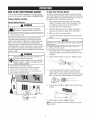
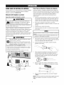
,_
This
is the safety
alert symbol.
is used to alertoryou
to potential personalinjuryhazards. Obey all safety messages
that follow
this symbolto
avoid Itpossibleinjury
death.
_Read with your
this pressurewasher.
manualcarefully and
become
familiar
Knowits
applications,
Hazard Symbols and Meaninos
its limitations, and any hazards involved.
The safety alert symbol (_.) is used with a signal word
(DANGER,CAUTION,WARNING), a pictorial and/or a safety
messageto alert you to hazards. BANGERindicates a hazard
which, if not avoided, willresult in death or serious injury.
WARNINGindicates a hazard which, if not avoided, could
result in death or serious injury. CAUTIONindicates a hazard
which, if not avoided, might result in minor or moderate
injury. NOTICEindicates a situation that could result in
equipment damage. Follow safety messages to avoid or
reduce the risk of injury or death.
Toxic Fumes
2
MovingParts
ElectricalShock
5-
SlipperySurface
Fire
© Sears Brands, LLC
Hazardous Chemical
Fall
FluidInjection
Explosion
Flying Objects
Operator'sManual
Kickback
Hot Surface
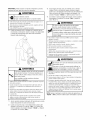
WARHJHG
WARHJNG
The engine exhaustfrom this productcontains
chemicalsknownto the State of California to cause
cancer,birthdefects, or otherreproductiveharm.
_
death.
Fireor explosion can cause severe burns or
DANGER
Contents are harmful or fatal if swallowed. Avoid
contact to eyes, skin or clothing. DO NOTtake
internally. Avoid breathing the mist or vapor.
Overexposureto eyes or skin can cause irritation.
Keep stabilizer out of the reach of children.
Fuel stabilizer is a hazardous chemical.**
. FreshStartTM fuel capis designedto hold a cartridgewhich
containsfuel stabilizer.
. If SWALLOWED,
callphysicianimmediately.DONOTinduce
vomiting. If inhaled,removeto fresh air. In caseof eyeor skin
contact,flushwith waterfor 15 minutes.
. Storeunopenedcartridgesin a cool, dry, wellventilatedarea.
Keepopencartridgein fuelcap, andfuelcapclosedon fueltank
whennot in use.
. In the caseof an emergency,contacta physicianimmediately
and call1-800-424-9300for materialsafetyinformation.
**Fuel stabilizer contains: 2,6-di-tret-butylpbenol (128-39-2) and aliphatic petroleum
distillate (64742-47-8).
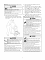
WARHJHG
Running engine gives off carbon monoxide, an
odorless, colorless, poison gas.
Breathing carbon monoxide can cause headache,
_
.
•
•
.
.
atigue, dizziness,
nausea,
fainting orvomiting,
death. confusion, seizures,
Some chemicals or detergents may be harmful if
inhaled or ingested, causing severe nausea,
fainting, or poisoning.
OperatepressurewasherONLYoutdoors.
Keepexhaustgasfrom enteringa confinedareathrough
windows,doors,ventilationintakes,or otheropenings.
DONOTstart or run engineindoorsor in an enclosedarea,
evenif windowsanddoorsare open.
Usea respiratoror maskwheneverthereis a chancethat
vapors maybe inhaled.
Readall instructionswith maskso you arecertainthe maskwill
providethe necessaryprotectionagainstinhalingharmful
vapors.
uel and its vapors are extremely flammable and
explosive.
WHENADDINGOR DRAININGFUEL
• TurnpressurewasherOFFand let it coolat least2 minutes
beforeremovingfuelcap. Loosencapslowlyto relievepressure
in tank.
• Fillor drain fueltank outdoors.
. DONOToverfilltank.Allowspacefor fuel expansion.
• If fuel spills,wait until it evaporatesbeforestartingengine.
. Keepfuelawayfrom sparks,openflames,pilot lights,heat,and
otherignitionsources.
. DONOTlight a cigaretteor smoke.
WHENSTARTINGEQUIPMENT
. Ensuresparkplug,muffler,fuel cap,andair cleanerarein
place.
• DONOTcrank enginewith sparkplug removed.
WHENOPERATINGEQUIPMENT
• DONOTtip engineor equipmentat anglewhichcausesfuel to
spill.
. DONOTsprayflammableliquids.
WHENTRANSPORTING
OR REPAIRINGEQUIPMENT
• Transport/repairwith fueltank EMPTYor with fuel shutoffvalve
OFF.
• Disconnectsparkplugwire.
WHENSTORINGFUELOBEQUIPMEHTWITH FUELIN TAHK
• Storeawayfrom furnaces,stoves,water heaters,clothes
dryers,or otherappliancesthat havepilot light or otherignition
sourcebecausetheycanignitefuelvapors.
WARHJHG
_¢
Contact
with power source can cause electric
isk of electrocution.
shock or burn.
• NEVERspraynearpowersource.
WARHJHG
WARHIHG
Starter cord kickback (rapid retraction) can result
in bodily injury. Kickback will pull hand and arm
_,_.<
The high pressure stream of water that this
equipment produces can cut through skin and its
toward engine faster than you can let go.
Broken bones, fractures, bruises, or sprains
could result.
• NEVERpull starter cord without first relieving spray gun
pressure.
. When starting engine, pull cord slowly until resistance is felt
and then pull rapidly to avoid kickback.
_
)ossible amputation.
nderlying tissues, leading to serious injury and
Spray gun traps high water pressure, even when
engine is stopped and water is disconnected,
which can cause injury.
• DO NOT allow CHILDRENto operate pressure washer.
. NEVERrepair high pressure hose. Replaceit.
• After eachstarting attempt, where engine fails to run, always
point spray gun in safe direction, press red button and squeeze
spray gun trigger to releasehigh pressure.
• NEVERrepair leaking connections with sealant of any kind.
Replaceo-ring or seal.
• Firmly grasp spray gun with both hands when using high
pressure spray to avoid injury when spray gun kicks back.
. Keep high pressure hose connected to pump and spray gun
while system is pressurized.
WARHIHG
• NEVERconnect high pressure hoseto nozzle extension.
• ALWAYS point spray gun in safe direction, press red button
and squeezespray gun trigger to releasehigh pressure, every
time you stop engine.
• NEVERaim spray gun at people, animals, or plants.
%
Use of pressure washer can create puddles and
slippery surfaces.
Kickback from spray gun can cause you to fall.
. Operate pressure washer from a stable surface.
• The cleaning area should haveadequate slopes and drainage to
reduce the possibility of a fall due to slippery surfaces.
. DO NOT secure spray gun in open position.
• DO NOT leave spray gun unattended while machine is running.
. NEVERuse a spray gun which does not have a trigger lock or
trigger guard in place and in working order.
. Always be certain spray gun, spray tips and accessories are
correctly attached.
. Be extremely careful if you must use the pressure washer from
a ladder, scaffolding, or any other similar location.
• Firmly grasp spray gun with both hands when using high
pressure spray to avoid injury when spray gun kicks back.
WARHIHG
area can
_
Contact with muffler
burns.
result in serious
_
structures
Exhaustheat/gases
or damage
can
fuel
ignite
tankcombustibles,
causing a fire.
• DO NOTtouch hot parts and AVOID hot exhaust gases.
WARHIHG
_
_¢
Unintentional sparking can result in fire or
electric shock.
WHENADJUSTINGORMAKINGREPAIRSTO YOUR
PRESSURE WASHER
. Disconnect the spark plug wire from the spark plug and place
the wire where it cannot contact spark plug.
WHENTESTINGFORENGINESPARK
. Allow equipment to cool before touching.
. Use approved spark plug tester.
• Keep at least 5 feet (152 cm) of clearance on all sides of
pressure washer including overhead.
• DO NOT check for spark with spark plug removed.
• Code of Federal Regulation (CFR)Title 36 Parks, Forests, and
Public Property require equipment powered by an internal
combustion engine to have a spark arrester, maintained in
effective working order, complying to USDAForest service
standard 5100-1C or later revision. In the State of California a
spark arrester is required under section 4442 of the California
Public resources code. Other states may havesimilar laws.
WARHJHG
[
NOTICE
High pressure spray may damage fragile items including
[g ass.
Starter hair,
and other
rotating
parts can entangle
hands,
clothing,
or accessories.
L
* NEVERoperate pressure washer without protective housing or
covers.
* DO NOTwear loose clothing, jewelry or anything that may be
caught in the starter or other rotating parts.
* Tie up long hair and remove jewelry.
WARNING
Risk of eye injury.
" _
JSpray can splash back or propel objects.
Always wear safety goggles when using this equipment or in
vicinity of where equipment is in use.
Before starting the pressure washer, be sure you are wearing
adequate safety goggles.
NEVERsubstitute safety glasses for safety goggles.
O NOT point
spray
gun
at glass when using MAX (0°) nozzle.
NEVERaim
spray
gun
at plants.
NOTICE
Improper treatment of pressure washer can damage it and
shorten its life.
If you have questions about intended use, ask dealer or contact
Sears.
NEVERoperate units with broken or missing parts, or without
protective housing or covers.
DO NOT by-pass any safety device on this machine.
DO NOT tamper with governed speed.
DO NOT operate pressure washer above rated pressure.
DO NOT modify pressure washer in any way.
Before starting pressure washer in cold weather, check all parts
of the equipment to be sure ice has not formed there.
NEVERmove machine by pulling on hoses. Use handle
provided on unit.
Check fuel system for leaks or signs of deterioration, such as
chafed or spongy hose, loose or missing clamps, or damaged
tank or cap. Correct all defects before operating pressure
washer.
This equipment is designed to be used with Sears authorized
parts ONLY. If equipment is used with parts that DO NOT
comply with minimum specifications, user assumes all risks
and liabilities.
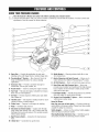
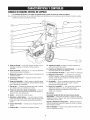
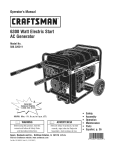
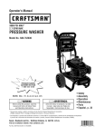
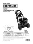
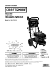
KNOWYOURPRESSUREWASHER
_Head Compare
the the
Operator'sManual
rules
before
pressurewasher.
illustrations with and
yoursafety
pressure
washer
tooperatingyour
familiarize yourself
with the locations of various controls and
adjustments. Savethis manual for future reference.
A - Spray Gun-- Controls the application of water onto
cleaning surface with trigger device. Includes trigger lock.
N - Bottle Bracket -- Cleaning solution bottle fits in wire
form bracket here.
B- PrecisionSpray TM Nozzles -- Max, General,Flush, Jet
Soap and Detergent Nozzles:for various cleaning
applications.
P - Nozzle Extensionwith QuickConnect -- Allows you to
switch between five different PrecisionSprayTM nozzles.
C - Accessory Tray -- Provides convenient storage for
accessories, such as gun, nozzles, etc.
S - Hose Wrap and High PressureHose -- Hose wrap
provides easy transport and handling of the high pressure
hose. Connect one end of hose to water pump and the
other end to spray gun.
O - Recoil Starter -- Used for starting the engine manually.
E - Fuel Tank -- Fill tank with regular unleaded fuel. Always
leave room for fuel expansion.
F - Air Filter -- Protects engine by filtering dust and debris
out of intake air.
6 - ThrottleLever -- Sets engine in starting mode for recoil
starter and stops a running engine.
H - ChokeLever -- Prepares a cold engine for starting.
J - Pump -- Develops high pressure.
I{ - Automatic Cool Down System -- Cycleswater through
pump when water reaches 125°-155°F. Warm water will
discharge from pump onto ground. This system prevents
internal pump damage.
L - High Pressure Outlet -- Connection for high pressure
hose.
M - Water Inlet -- Connectionfor garden hose.
R - Oil Fill/Dipstick -- Check, add and drain engine oil here.
T - Fold DownHandle -- Handle and accessory tray fold flat
atop cold engine for space-saving storage.
U - Project Pro@ PerfectlVlWMSiphon -- Mixes concentrate
with pressure washer spray.
Items Not Shown:
Data Tag (near rear of base plate} -- Provides model and
serial number of pressure washer. Pleasehave these readily
available if calling for assistance.
Safety Goggles-- Always usethe enclosed safety goggles
when running your pressure washer.
Warning/Operating instructionsTag -- identifies hazards
and proper procedure to start/stop pressure washer.
Your pressure washer requires some assembly and is ready
for use only after it has been properly serviced with the
recommended oil and fuel.
4.
5.
If you have any problemswith the assemblyof your
pressurewasher, please call the pressurewasher heipline
at 1-800-222-3135.
6.
7.
Add oil to engine crankcase.
Add fuel to fuel tank and Fresh Start fuel cartridge to fuel
cap.
Connect pressure hose to spray gun and pump.
Connectwater supply to pump.
8.
Attach nozzleextension to spray gun.
UNPACKTHE PRESSUREWASHER
9.
Select/attach quick connect PrecisionSprayTM nozzle to
nozzle extension.
1.
Remove everything from carton except pressure washer.
2.
Open carton completely by cutting each corner from top
to bottom.
3.
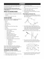
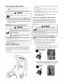
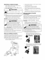
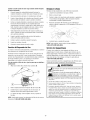
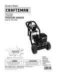
Attach Handle and Accessory Tray
1.
Remove pressure washer from carton.
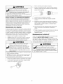
Placehandle (A) onto handle supports (B) connected to
main unit. Make sure holes (C) in handle align with holes
(C) on handle supports.
,
CARTONCONTENTS
Checkall contents. If any parts are missing or damaged, call
the pressure washer helpline at 1-800-222-3136.
• Main Unit
•
Handle
•
Accessory Tray
•
•
High Pressure Hose
Spray Gun
•
•
NozzleExtensionwith Quick Connect Fitting
Oil Bottle
•
Hose Wrap
•
Parts Bag (which includes the following):
•
Operator's Manual
•
Owner's Registration Card
•
Safety Goggles
•
Bottle BracketWirdorm (2)
•
PerfectMixTM Siphoning Unit/Hose
•
DetergentSiphoning Hose/Filter
•
Bagcontaining 5 PrecisionSprayTM Nozzles
•
FreshStart FuelCartridge
•
HandleFasteningHardwareKit (which includes):
•
Handle Bolts (2)
•
•
Carriage Bolt (2)
Plastic Knobsfor Handle (2)
•
•
Rope Guide (1)
Plastic Knob (3)
•
Tree Clips (4)
J
2.
i
Insert handle carriage bolts (D) through holes from
inside of unit and attach a plastic knob (E) from outside
of unit. Tighten by hand. By loosening both knobs to the
middle section of the attachment bolt, the upper handle
can fold forward to store flat atop the cold engine.
NOTE:DONOT fold the handle down while the engine is hot.
Placeaccessory tray (F) over holes (6) on handle
(viewing from back of unit). Push the tree clips (N) into
the holes until they sit flat against the accessory tray.
Becomefamiliar with each piece before assembling the
pressure washer. Identify all contents with the illustration on
page 6. If any parts are missing or damaged, call the
pressure washer helpline at 1-800-222-3136.
ASSEMBLINGPRESSUREWASHER
Your Craftsman pressure washer will need assembly before
operation:
1.
2.
Fill out and send in registration card.
Attach handle, accessorytray, rope guide and hose wrap.
3.
Connect detergent siphon hose to pump.
,
L
I
I
Insert multi-colored PrecisionSprayTM nozzlesand other
supplied accessories in spaces provided in accessory
tray. See How to Use Accessory Tray.
Attach rope guide (A) through handle with plastic knob
(B). Tighten by hand. Route engine recoil rope through
guide.
,
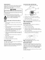
Standard Siphon Tube
Cleartube with filter:
When using the clear siphon tube, dilute
1 part PerfectMixTM ExtremeConcentrate
to 16 parts water (4 oz of concentrate
makes 1/2 gallon of mix.)
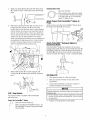
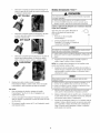
Attach Project Pro@ PerfectMix
Pump
Align hose wrap (C) to the back side of accessory tray.
Locate notch with "unlock" icon (D) on hose wrap.
Position notch at top with hose wrap in vertical position.
Clips in the back of accessory tray should slide into the
grooves on the inside surface of hose wrap. Slide hose
wrap on back of accessory tray and rotate 1/8 turn until
"locked"icon (E) is in vertical position. Hose wrap is
easily removed from the accessorytray for wrapping and
unwrapping of the high pressure hose. A clip to secure
the hose on the reel makes it easy to wrap the hose
while it is detached from the accessory tray.
,
TM
Siphon to
Attach the hose end of the blue PerfectMWMSiphon (J) to
the barbed hose fitting (K) on the pump.
Attach PerfectMix TM Detergent Siphon to
Concentrate Bottle
Place PerfectMixTM bottle (not included) in the wire-form
bracket on the handle. Removecap from bottle and insert the
PerfectMixTM Siphon (L). Screw the siphon unit to the top of
the bottle (M). Usethe clip on the cap (L) to snap siphon to
wire form bracket when siphon is not in a concentrate bottle.
-%
\
®
Attach bottle brackets (F) to handle supports with
carriage bolt (G) and black plastic knob (H). Tighten by
hand.
,
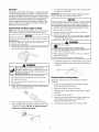
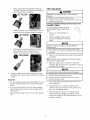
Add Enoine Oil
1.
Placepressure washer on a flat, ]eve]surface.
2.
Cleanarea around oil fill and remove yellow oil fill
cap/dipstick.
3.
Using oil funnel (optional), slowly pour contents of
provided oil bottle into oil fill opening.
NOTICE
2-1N-1 Soap System
The pressure washer is equipped with two detergent
siphoning hoses.
TM
Project Pro PerfectMix
Siphon
Blue tube with blue bottle cap:
,
i
When using the blue PerfectMixTM siphon, use
the PerfectMixTM Extreme Concentrate straight
from the bottle
Improper treatment of pressure washer can damage it and
shorten its life.
DONOTattemptto crankor startthe enginebeforeit hasbeen
properlyservicedwith the recommended
oil. This may resultin
an enginefailure.
4.
Replace oil fill cap/dipstick and fully tighten.
Add FueJ
Fuel must meet these requirements:
*
Clean, fresh, unleadedgasoline.
.
A minimum of 87 octane/87 AKI (91 RON). High altitude
use, see High Altitude.
*
Gasolinewith up to 10% ethanol (gasohol) or up to 15%
MTBE (methyl tertiary butyl ether) is acceptable.
HOTJCE
Avoid pressure washer damage.
Failureto follow Operator's Manual for fuel
recommendations voids warranty.
DONOTuseunapprovedgasolinesuchas E85.
DONOTmix oil in gasoline.
DONOTmodifyengineto run on alternatefuels.
To protect the fuel system from gum formation, mix in a fuel
stabilizerwhen adding fuel. See Storage.All fuel is not the
same. If you experiencestarting or performanceproblems after
using fuel, switch to a different fuel provider or changebrands.
This engineis certified to operateon gasoline. Theemission
control system for this engine is EM (Engine Modifications).
WARHJHG
f_
Fueland its vapors are extremely flammable and
explosive.
To avoid engine problems, the fuel system should be treated
with a fuel preserver or emptied before storage of 30 days or
longer. If adding a fuel preserver, fill the fuel tank with fresh
fuel. if only partially filled, air in the tank will promote fuel
deterioration during storage, if fuel preserver is not used,
drain the fuel tank, start the engine and let it run until the fuel
lines and carburetor are empty. Use fresh fuel next season.
See Storage for additional information.
NEVERuse engine or carburetor cleaner products in the fuel
tank as permanent damage may occur.
FreshStart FuelCap
Adding fuel preserver helps keep fuel fresh and carburetors
clean for easier starting, all season long. This new fuel cap
automatically drips concentrated fuel preserver into your fuel
tank.
, DANGER
Contents are harmful or fatal if swallowed. Avoid
_
ontact to eyes, skin or clothing. DO NOTtake
internally. Avoid breathing the mist or vapor.
Overexposureto eyes or skin can cause irritation.
Keepstabilizer out of the reachof children.
Fuelstabilizer is a hazardous chemical.**
o If SWALLOWED,
callphysicianimmediately.
o In the caseof an emergency,contacta physicianimmediately
andcall 1-800-424-9380for materialsafetyinformation.
**Fuel stabilizer contains: 2,6-di-tret-butylphenol
distillate (64742-47-8).
death.
Fire or explosion can cause severe burns or
(128-39-2) and alipbatie petroleum
Placecartridge into fuel cap.
WHEHADDINGFUEL
* TurnpressurewasherOFFand let it coolat least2 minutes
beforeremovingfuelcap. Loosencapslowlyto relievepressure
in tank.
Fillfueltank outdoors.
DONOToverfilltank.Allowspacefor fuelexpansion.
. If fuel spills,wait until it evaporatesbeforestartingengine.
* Keepfuelawayfrom sparks,openflames,pilot lights,heat,and
otherignitionsources.
DONOTlight a cigaretteor smoke.
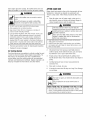
1.
Cleanarea around fuel fill cap, remove cap.
2.
Slowly add regular unleaded fuel (A) to fuel tank (U). Be
careful not to overfill. Allow about 1.5" (4 cm) (C) of tank
space for fuel expansion.
/
,
3.
Push to "snap" cartridge into place.
Removetab to expose membrane.
IMPORTANT:DO NOT remove the silver foil seal on the
opposite side.
3.
Install fuel cap and wait for any spilled fuel to evaporate.
CAUTION! Alcohol-blended fuels (called gasohol, ethanol or
methanol) can attract moisture, which leads to separation and
formation of acids during storage. Acidic gas can damagethe
fuel system of an engine while in storage.
4.
Reinstall fuel cap on fuel tank.
5.
Periodically check the cartridge to ensure there is still
fuel stabilizer inside. If it is empty, remove cartridge and
replace.
HighAltitude
4.
At altitudesover5,000 feet (1524 meters),a minimum 85 octane
/ 85 AKI (89 RON)gasolineis acceptable.To remainemissions
compliant,high altitudeadjustmentis required.Operationwithout
this adjustmentwill causedecreasedperformance,increasedfuel
consumption,and increasedemissions.Seea qualifiedSears
dealerfor high altitudeadjustment information.Operationof the
engineat altitudesbelow2,500 feet (762 meters)with the high
altitudekit is not recommended.
Run water through garden hose for 30 seconds to flush
it of debris. Turn off water.
IMPORTANT:DO NOTsiphon standing water for the water
supply. Use ONLYcold water (less than I O0°F).
HOTICE
Using a OneWay Valve (vacuum breaker or check valve) at
pump inlet can cause pump or inlet connector damage.
ThereMUSTbe at leastten feet of unrestrictedgardenhose
betweenthepressurewasherinletand anydevice,suchas a
vacuumbreakeror checkvalve.
Connect Hose and Water Supply to Pump
NOTE:Removeand discard the shipping caps from the pump's
high pressure outlet and water inlet beforeattaching hoses.
Damageto equipmentresultingfrom failureto followthis
instructionwill void warranty.
NOTICE
5.
DO NOT run the pump without the water supply connected
and turned on.
Damageto equipmentresultingfrom failureto follow this
instructionwill void warranty.
Connectgarden hose (not to exceed 50 feet in length) to
water inlet. Tighten by hand.
WARHIHG
,_
Uncoil high pressure hose and attach one end of hose to
base of spray gun. Tighten by hand.
Risk of eye injury.
_Spray
can splash back or propel objects.
Alwayswearsafetygoggleswhen usingthis equipmentor in
vicinityof whereequipmentis in use.
Beforestartingthe pressurewasher,be sureyouare wearing
adequatesafetygoggles.
NEVERsubstitutesafetyglassesfor safetygoggles.
6. Turn ON the water, press red button (B) on the gun and
squeezethe trigger to purge the pump system of air and
impurities.
WARHIHG
The high pressure stream of water that this
_
quipment tissues,
producesleading
can cuttothrough
and
its
underlying
serious skin
injury
and
_ossibleamputation.
* NEVERconnecthigh pressurehoseto spraytip extension.
* Keephigh pressurehoseconnectedto pumpand spraygun
whilesystemis pressurized.
* Alwaysbecertainspraygun,spraytips and accessoriesare
correctlyattached.
2.
,
Checklist Before Starting Engine
Reviewthe unit to ensure you have performed all of the
following:
1.
Attach other end of high pressure hose to high pressure
outlet on pump. Tighten by hand.
2.
Before connecting garden hose to water inlet, inspect
inlet screen (A). Cleanscreen if it contains debris or have
it replacedif damaged. DO NOTrun pressurewasher if
inlet screenis damagedor missing.
10
Be sure to read Safety Rules and Operationsections
before using the pressure washer.
Make sure handle is in place and secure.
3.
Checkthat oil has been added to proper level in engine
crankcase.
4.
Add proper fuel to fuel tank.
5.
Checkfor proper hose connections (high pressure and
water supply) and that there are no kinks, cuts, or
damageto the high pressure hose.
6.
Provide proper water supply (not to exceed IO0°F).
HOWTO USEYOUR PRESSUREWASHER
To Start Your Pressure Washer
If you haveany problems operating your pressure washer,
please call the pressure washer helpline at 1-808-222-3136.
To start your engine-powered pressure washer for the first
time, follow these instructions step-by-step. This information
also applies whenever you start the engine after you have let
the pressure washer sit idle for at least a day.
Pressure Washer Location
PressureWasherClearance
1.
Placepressure washer outside near an water source
capable of supplying water at a flow rate greater than
3.7 gallons per minute and no less than 20 PSI at
pressure washer end of garden hose.
2.
Checkthat high pressure hose is tightly connected to
spray gun and pump. See Assemblyfor illustrations.
3.
Make sure unit is in a level position.
4.
Connectgarden hose to water inlet on pressure washer
pump.
WARNING
_
Exhaustheat/gases
can
ignitecombustibles,
structures
or damage
fuel
tank causing a fire.
• Keepat least5 ft. (152 cm) clearanceon all sidesof pressure
washerincludingoverhead.
Placepressure washer outdoors in an area that will not
accumulate deadly exhaust gas. DO NOT place pressure
washer where exhaust gas (A) could accumulate and enter
inside or be drawn into a potentially occupied building.
Ensureexhaust gas is kept away from any windows, doors,
ventilation intakes, or other openings that can allow exhaust
gas to collect in a confined area. Prevailingwinds and air
currents should be taken into consideration when positioning
_ressurewasher.
[
run
pO
the
andNOT
turned on.
pump
without the
water supply
connected
L instructionwill
amageto equipment
resultingfrom failureto followthis
void warranty.
5.
Turn ONthe water, press red button on the gun and
squeezethe trigger to purge the pump system of air and
impurities.
6.
Attach nozzleextension to spray gun. Tighten by hand.
WARHIHG
Running engine gives off carbon monoxide, an
NOTICE
Breathingcarbon
monoxide
can cause headache,
dorless, colorless,
poison gas.
fatigue, dizziness, vomiting, confusion, seizures,
nausea, fainting or death.
. OperatepressurewasherONLYoutdoors.
• Keepexhaustgasfrom enteringa confinedareathrough
windows,doors,ventilationintakes,or otheropenings.
• DONOTstart or run engineindoorsor in an enclosedarea,
evenif windowsanddoorsare open.
_
Choose PrecisionSprayTM nozzle you want to use, pull
back on collar of nozzleextension, insert nozzle and
releasecollar. Tug on nozzle to make sure it is securely in
place. See How to Use PrecisionSpraSMNozzleSystem.
8.
Move throttle lever (B) to "Fast" position, shown here as
a rabbit.
9.
Move choke lever (C) to "Choke" position.
NOTE:For a warm engine, be sure the choke lever is in the
"Run" position.
IMPORTANT:
Before
starting
thepressure
washer,
besure
11. Return recoil starter slowly. DO NOT let rope "snap
back" against starter.
¢ou are wearing adequatesafety goggles.
12. When engine starts, slowly move choke lever to "Run"
position, as engine warms. If engine falters, move choke
lever to "Choke" position, then to "Run" position.
WARNING
Risk of eye injury.
_Spray
can splash back or propel objects.
Alwayswearsafetygoggleswhenusingthis equipmentor in
vicinity of whereequipmentis in use.
Beforestartingthe pressurewasher,be sureyou are wearing
adequatesafetygoggles.
NEVERsubstitutesafetyglassesfor safetygoggles.
13. After each starting attempt, where engine fails to run,
always point gun in safe direction, press red button and
squeeze spray gun trigger to releasehigh pressure.
Move choke lever to "Cheke" position, and repeat steps
10 through 12.
10. When starting engine, position yourself as
recommended and grasp starter grip handle and pull
slowly until you feel some resistance. Then pull rapidly
to start engine.
NOTE:Always keepthe throttle lever in the "Fast" position
when operating the pressure washer.
14. If engine fails to start after six pulls, move choke lever to
"Run" position, and repeatsteps 10 through 12.
WARNING
The high pressure stream of water that this
equipment produces can cut through skin and its
_
_ossible amputation.
nderlying tissues, leading to serious injury and
Spray gun traps high water pressure, even when
engine is stopped and water is disconnected,
which can cause injury.
• DONOTallowCHILDREN
to operatepressurewasher.
• Keephigh pressurehoseconnectedto pumpand spraygun
whilesystemis pressurized.
, NEVERaim spraygun at people,animals,or plants.
• DONOTsecurespraygun in openposition.
• DONOTleavespraygun unattendedwhile machineis running.
, NEVERusea spraygun whichdoesnot havea triggerlock or
triggerguardin placeandin workingorder.
, Alwaysbe certainspraygun,spraytips and accessoriesare
correctlyattached.
WARNING
WARNING
Starter cord kickback (rapid retraction) can result
in bodily injury. Kickback will pull hand and arm
_!_.<
toward engine faster than you can let go.
Broken bones, fractures, bruises, or sprains
could result.
* NEVERpull startercordwithout first relievingspraygun
pressure.
* Whenstartingengine,pull cord slowlyuntil resistanceis felt
andthenpull rapidlyto avoidkickback.
* After eachstartingattempt,whereenginefails to run,always
pointspraygun in safedirection,pressred buttonand squeeze
sprayguntriggerto releasehigh pressure.
Firmlygraspspraygun with bothhandswhenusinghigh
pressuresprayto avoidinjury whenspraygun kicks back.
_
ontact with muffler area can result in serious
burns.
_
structures
or damage
fuel
tankcombustibles,
causing a fire.
Exhaustheat/gases
can
ignite
* DONOTtouch hot partsand AVOIDhot exhaustgases.
, Allowequipmentto cool beforetouching.
* Keepat least5 feet (152cm) of clearanceon all sidesof
pressurewasherincludingoverhead.
, Codeof FederalRegulation(CFR)Title 36 Parks,Forests,and
PublicPropertyrequireequipmentpoweredby an internal
combustionengineto havea sparkarrester,maintainedin
effectiveworkingorder,complyingto USDAForestservice
standard51B0-1Cor later revision.Inthe Stateof Californiaa
sparkarresteris requiredundersection4442 of the California
Publicresourcescode.Otherstatesmay havesimilarlaws.
12
How to Stop Your Pressure Washer
1.
2.
,
Releasespray gun trigger and let engine idle for two
minutes.
Move throttle to SLOW position, then STOPposition.
3.
Insert multi-colored spray tips in spaces provided in
accessory tray.
4.
Wrap high pressure hose on hose wrap then attach hose
wrap to back of accessory tray.
5.
Hook provided on back of accessory tray for safely
storing safety goggles.
WARHIHG
.,i_j
Backfire, fire or engine damagecould occur.
How to Use PrecisionSpray TM Nozzle System
* DONOTstopenginebymovingchokeleverto "Cheke"position.
3.
Placespray gun through hole on accessory tray on right
side of unit.
The quick-connect on the nozzle extension allows you to
switch between five different PrecisionSprayTM system
nozzles. PrecisionSprayTM nozzlescan be changed while
pressure washer is running once spray gun trigger lock is
engaged.
ALWAYSpoint spray gun in a safe direction, push red
button and squeeze spray gun trigger to releaseretained
high water pressure.
IMPORTANT:Spray gun traps high water pressure, even
when engine is stopped and water is disconnected.
WARHING
WARNING
The high pressure stream of water that this
The high pressure stream of water that this
equipment produces can cut through skin and its
,_
_ossibleamputation.
underlying tissues, leading to serious injury and
Spray gun traps high water pressure, even when
engine is stopped and water is disconnected,
which can cause injury.
. NEVERexchangePrecisionSpray
TM nozzles
withoutthe trigger
lock beingengagedon the spraygun.
• DONOTtwist PrecisionSpray
TM nozzles
whilespraying.
FolJowthese instructionsto changePrecisionSprayTM
. Keephigh pressurehoseconnectedto pumpand spraygun
whilesystemis pressurized.
• ALWAYSpointspraygun in safedirection,pressred button
and squeezespraygun trigger,to releasehigh pressure,every
time youstop engine.
flozzJes:
Howto UseAccessoryTray
1.
Pull back collar on quick-connect and pull current
PrecisionSprayTM nozzle off. Store PrecisionSprayTM
nozzles in holder provided on the accessory tray.
2.
Select desired PrecisionSprayTM nozzle:
*
The unit is equipped with an accessorytray with places to
store your spray gun, nozzle extension and quick connect
PrecisionSprayTM nozzles. There is also a detachable hose
wrap at the back of the accessorytray to hold your high
pressure hose.
1.
underlying
serious skin
injury
and
quipment tissues,
producesleading
can cuttothrough
and
its
)ossible amputation.
_
Select orange general PrecisionSprayTM nozzle for all
purpose cleaning. Cleans vinyl siding, brick patios,
concrete driveways and other surfaces.
Placespray tip extension in clip on back of accessorytray.
Select red max PrecisionSpray
TM nozzlefor maximum
cleaning. Greatfor cleaning stubborn stains, including
grease,tar, wax, and other hard to remove stains.
MAX
13
•
Select
cyanjetflushPrecisionSpray
nozzle for
2-1N-1 Soap System
TM
quick high flow clean up and long reach cleaning of
second story siding and windows.
CAUTIOH
Chemicals can cause bodily injury, and/or property
damage.
NEVERusecausticliquidwith pressurewasher.
UseONLYpressurewashersafedetergents/soaps.
Followall
manufacturersinstructions.
CJeaningand ApplyingDetergent with the Project Pro@
PerfectMJxTM Siphon
•
To apply undiluted detergent using the
blue PeffectMixTM siphon, follow these
steps:
Select magenta jet soap PrecisionSprayTM nozzleto
launch soap to second story siding and windows.
1.
Review use of PrecisionSprayTM
nozzles.
2.
Attach PerfectMWMsiphon hose to
pump and PerfectMixTM
bottle,
concentrate
i
ii'i"
ti
NOTICE
Contact with the hot muffler can damage detergent
siphoning tube.
Wheninsertingthe siphoninto a detergentsolutionbottle,
routethe tubeso asto keepit from inadvertentlycontactingthe
hot muffler.
Select black fan soap PrecisionSprayTM nozzle for
general cleaning. Greatfor applying soap to
vehicles, boats, driveways, decks, and patios.
FAN SOAP
3.
Make sure fan soap (black) or jet soap nozzle (magenta)
is installed.
NOTE:Detergentcannot be applied with the high pressure
nozzles (Cyan,Orange or Red).
4. Make sure garden hose is connected to water inlet.
Checkthat high pressure hose is connected to spray gun
and pump. Turn on water.
NOTICE
3.
You must attach all hoses before you start th_
Startingthe enginewithout all the hosesconnectedandwithout
thewaterturnedONwill damagethe pump.
Damageto equipmentresultingfrom failureto followthis
instructionwill void warranty.
Pull back on collar, insert new PrecisionSprayTM nozzle
and releasecollar. Tug on nozzleto makesure it is securely
in place.
Usage Tips
*
For most effective cleaning, keep PrecisionSprayTM nozzle
from 8 to 24 inches (20 to 61 cm) away from cleaning
surface.
.
If you get PrecisionSprayTM nozzle too close, especially
using a high pressure nozzle,you may damage surface
being cleaned.
*
DO NOTget closer than 6 inches (15 cm) when cleaning
tires.
14
5.
Start engine following instructions How to Start Your
Pressure Washer.
6.
Apply detergent to a dry surface, starting at lower
portion of area to be washed and work upward, using
long, even, overlapping strokes.
7.
Allow detergent to "soak in" for 3-5 minutes before
washing and rinsing. Reapply as neededto prevent
surface from drying. DO NOT allow detergent to dry on
(prevents streaking).
CJeaningand ApplyingDetergent with the Standard Clear
Siphon
Pressure Washer Rinsing
To apply diluted detergent using the
standard clear siphon tube, follow these
steps:
1. Review use of PrecisionSprayTM
nozzles.
For Rinsing:
1. Remove low pressure nozzle from nozzle extension.
2.
Attach clear siphon hose to barbed
fitting on pump.
3.
Mix detergent solution as required by job.
4.
Place small filter end of clear siphoning tube into
container with diluted solution as described above.
2.
Selectand installdesired high pressure nozzle following
instructions How to Use PrecisionSpraSMNozzleSystem.
3.
Keepspray gun a safe distance from area you plan to
spray.
Kickback from
NOTE:DO NOT insert standard siphon hose in Extreme
Concentrate. Failureto dilute concentrate will cause excessive
application and consumption of solution.
NOTICE
Apply a high pressure spray to a small area and then
check surface for damage. If no damage is found, you
can assume it is okay to continue rinsing.
Contact with the hot muffler can damagedetergent
siphoning tube.
Wheninsertingthe siphonintoa detergentsolutionbottle,
routethe tubeso asto keepit from inadvertentlycontactingthe
hot muffler.
Start at top of area to be rinsed, working down with
same overlapping strokes as you used for cleaning.
Make sure fan soap (black) or jet soap nozzle (magenta)
is installed.
Cleaning DetergentSiphoning Tube
If you used the clear detergent siphoning tube, you must
flush it with clean water before stopping the engine.
1. Placedetergent siphoning tube/filter in a bucket full of
clean water.
NOTE:Detergentcannot be applied with the high pressure
nozzles (Cyan, Orange or Red).
6. Make sure garden hose is connected to water inlet.
Checkthat high pressure hose is connected to spray gun
and pump. Turn on water.
NOTICE
You must attach all hoses before you start the engine.
Startingthe enginewithoutall the hosesconnectedandwithout
the waterturnedONwill damagethe pump.
Damageto equipmentresultingfrom failureto follow this
instructionwill void warranty.
7.
Start engine following instructions How to Start Your
Pressure Washer.
8.
Apply detergent to a dry surface, starting at lower
portion of area to be washed and work upward, using
long, even, overlapping strokes.
9.
Allow detergent to %oak in" for 3-5 minutes before
washing and rinsing. Reapplyas needed to prevent
surface from drying. DO NOTallow detergent to dry on
(prevents streaking).
to fall.
• Operatepressurewasherfrom a stablesurface.
, Beextremelycarefulif you mustusethe pressurewasherfrom
a ladder,scaffolding,or anyothersimilarlocation.
, Firmlygraspspraygunwith both handswhenusing high
pressuresprayto avoidinjury whenspraygun kicks back.
NOTE:Make sure the filter is fully submerged in fluid while
applying solution.
5.
spray gun can cause you
2.
Remove high pressure nozzle from nozzle extension.
3.
Select and install a soap nozzle following instructions
How to Use PrecisionSprayTM Nozzle System.
4.
Flush for 1-2 minutes.
5.
Shut off engine following instructions How to Stop
Pressure Washerand turn off water supply.
6.
ALWAYS point spray gun in a safe direction push red
button and squeezespray gun trigger to release retained
high water pressure.
iMPORTANT:Spray gun traps high water pressure, even
when engine is stopped and water is disconnected.
Automatic Cool Down System (Thermal Relief)
If you run the engine on your pressure washer for
3-5 minutes without pressing the trigger on the spray gun,
circulating water in the pump can reach temperatures above
125°F. The system engagesto cool the pump by discharging
the warm water ontothe ground.
IMPORTANT:You must flush the detergent siphoning system
after each use by placing the filter into a bucket of clean
water, then run the pressure washer in low pressure for 1-2
minutes.
15
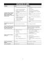
EHGJNETECHNICALJNFORMATJOH
PRODUCTSPECJFICATJOHS
This is a single cylinder, overhead valve (OHV), air cooled
engine, it is a low emissions engine.
Pressure Washer Specifications
Max Outlet Pressure .......................
Max How Rate .............................
In the State of California, Model 120000 engines are certified
by the California Air Resources Board to meet emissions
standards for 125 hours. Such certification does not grant
the purchaser, owner or operator of this engine any
additional warranties with respectto the performance or
operational life of this engine. The engine is warranted solely
according to the product and emissions warranties stated
elsewhere in this manual.
Detergent Mix ........................
Water Supply Temperature ..........
Shipping Weight .............................
3,000 PSi
2.7 GPM
Use as directed
Not to exceed IO0°F
71 Ibs.
Engine Specifications
Bore .................................
2.69 in. (68mm)
Stroke ...............................
2.04 in. (52mm)
Displacement ........................
11.57 in. (190 cc)
SparkPlug
Type: .....................
Briggs & Stratton 491055S
SetGap To: ......................
O.020inch(0.50ram)
Armature Air Gap: ...........
0.006-0.014in.(O.15-O.36mm)
Valveclearancewith valvespringsinstalledand piston1/4in.
(6 ram)pasttop deadcenter(checkwhenengineis cold).
Intake ....................
0.004-0.006 in.(0.10-0.15mm)
Exhaust ..................
0.004-0.008 in.(0.10-0.20mm)
FuelCapacity...............................
1.6 Quarts
Oil Capacity .......................
22 Ounces(0.65 liter)
Power Ratings
The gross power rating for individual gas engine models is
labeled in accordance with SAE (Society of Automotive
Engineers)code J1940 (Small Engine Power & Torque
Rating Procedure), and rating performance has been
obtained and corrected in accordancewith SAEJ1995
(Revision 2002-05). Torque values are derived at 3060 RPM;
horsepower values are derived at 3600 RPM. Actual gross
engine power will be lower and is affected by, among other
things, ambient operating conditions and engine-to-engine
variability. Given both the wide array of products on which
engines are placed and the variety of environmental issues
applicable to operating the equipment, the gas engine will not
develop the rated gross power when used in a given piece of
power equipment (actual "on-site" or net power). This
difference is due to a variety of factors including, but not
limited to, accessories (air cleaner, exhaust, charging,
cooling, carburetor, fuel pump, etc.), application limitations,
ambient operating conditions (temperature, humidity,
altitude), and engine-to-engine variability. Due to
manufacturing and capacity limitations, Briggs & Stratton
may substitute an engine of higher rated power for this
Series engine.
NOTE:For practical operation, the engine load should not
exceed 85% of rated power. Engine power will decrease
3-1/2% for each 1,000 feet (300 meters) above sea level and
1% for each 10° F (5.6° C) above 77° F (25° C). It should
operatesatisfactorily at an angle up to 15°.
This pressure washer is rated in accordanceto the Pressure
Washer Manufacture Association (PWMA) standard PW101
(Testing and Rating Performance of Pressure Washers).
16
OWHER'SRESPOHSIBILITIES
Pump Oil
Follow the hourly or calendar intervals, whichever occurs
first. More frequent service is required when operating in
adverse conditions noted below.
DO NOTattempt any oil maintenance on this pump. The
pump is pre-lubricated and sealed from the factory, requiring
no additional maintenancefor the life of the pump.
Maintenance
Emissions Control
Schedule
Maintenance, replacement, or repair of the emissions
control devices and systemsmay be performedby any nonroad engine repair establishmentor individual. However,
to obtain "no charge" emissions control service, the work
must be performed by a factory authorized dealer. Seethe
Emissions Warranty.
* Changeengine oil
* Check/clean water inlet screen1
Before Each Use
, Check high pressure hose
, Check detergent siphoning hose
1.
2.
Checkengine oil level.
Cleandebris.
, Checkspray gun and assembly for leaks
3.
Checkwater inlet screen for damage.
* Clean debris
4.
5.
Checkhigh pressure hose for leaks.
Checkgun and nozzle extension assembly for leaks.
6.
Purge pump of air and contaminants.
* Checkengine oil level
PRESSURE
WASHERMAINTENANCE
, Service engine air cleaner2
Clean Debris
Daily or before use, clean accumulated debris from pressure
washer. Keep linkage, spring and controls clean. Keep area
around and behind muffler free from any combustible debris.
Inspect cooling air slots and openings on the pressure
washer. These openings must be kept clean and
unobstructed.
, Changeengine oil2
* Service spark arrester
, Service spark plug
Pressure washer parts should be kept clean to reduce the
risk of overheating and ignition of accumulated debris.
* Use a damp cloth to wipe exterior surfaces clean.
, Cleancooling system2
Clean if clogged. Replace if perforated or torn.
[
Service more often under dirty or dusty conditions.
NOTICE
Improper treatment of pressure washer can damage it and
|shorten ts fe.
General Recommendations
Regular maintenancewill improve the performance and
extend the life of the pressure washer. Seeany Sears or
other qualified service dealer for service.
L DONOTinsert anyobjectsthroughcoolingslots.
The pressure washer warranty does not cover items that
have been subjected to operator abuse or negligence. To
receivefull value from the warranty, the operator must
maintain pressure washer as instructed in this manual
including proper storage as detailed in Storage.
•
Use a soft bristle brush to loosen caked on dirt, oil, etc.
•
Use a vacuum cleaner to pick up loose dirt and debris.
Check and Clean Inlet Screen
Examinegarden hose inlet screen. Cleanif it is clogged or
replace if it is torn.
Some adjustments will need to be made periodically to
properly maintain your pressure washer.
All service and adjustments should be made at least once
each season. Follow the requirements in the Maintenance
Schedulechart above.
NOTE:Oncea year you should clean or replace the spark
plug and replace the air filter. A new spark plug and clean air
filter assure proper fuel-air mixture and help your engine run
better and last longer.
17
Check High Pressure Hose
3.
Remove nozzlefrom end of nozzle extension.
High pressure hoses can develop leaks from wear, kinking,
or abuse. Inspect hose before each use. Checkfor cuts,
leaks, abrasions, bulging of cover, or damage or movement
of couplings. If any of these conditions exist, replace hose
immediately.
4.
Use a small paper clip to free any foreign material
clogging or restricting nozzle (A).
WARHIHG
The high pressure stream of water that this
,
_
quipment tissues,
producesleading
can cuttothrough
and
its
underlying
serious skin
injury
and
_ossibleamputation.
* NEVERrepairhigh pressurehose.Replaceit.
* ReplacementhoseratingMUSTexceedmaximumpressure
ratingof unit.
Remove nozzleextension from spray gun.
6.
Using a garden hose, remove additional debris by back
flushing water through nozzle extension. Back flush
between 30 to 60 seconds.
7.
Reinstallnozzleinto nozzleextension.
8.
Reconnect nozzle extension to spray gun.
9.
Make sure garden hose is connected to water inlet.
Checkthat high pressure hose is connected to spray gun
and pump. Turn on water.
Check Gun and Hozzle Extension
Examinehoseconnectionto spray gun and makesure it is
secure.Testtrigger by pressingit and makingsure it springs
back into placewhenyou releaseit. Do not depressred button
and test trigger. You should not be ableto press trigger. Replace
spray gun immediatelyif it fails any of these tests.
HozzleMaintenance
10. Start engine following instructions How to Start Your
Pressure Washer.
A pulsing sensation felt while squeezingthe spray gun trigger
may be caused by excessive pump pressure. The principal
cause of excessive pump pressure is a nozzle clogged or
restricted with foreign materials, such as dirt, etc. To correct
the problem, immediately clean the nozzle following these
instructions:
1.
Shut off engine and turn off water supply.
2.
ALWAYSpoint spray gun in a safe direction, press red
button and and squeezespray gun trigger to release
retained high water pressure.
11. Test pressure washer by operating with each quick
connect nozzle.
O-Ring Maintenance
Purchase an O-Ring Repair Kit at your local Sears or by
calling 1-800-4-NIY-HOIVlE(469-4663) or online at
www.sears.com. It is not included with the pressure washer.
This kit includes replacement o-rings, rubber washer and
water inlet filter. Refer to the instruction sheet provided in the
kit to service your unit's o-rings.
WARHIHG
WARHIHG
The high pressure stream of water that this
equipment produces can cut through skin and its
The high pressure stream of water that this
,p_
equipment
producesleading
can cuttothrough
and
its
underlying tissues,
serious skin
injury
and
)ossible amputation.
* NEVERrepairleakingconnectionswith sealantof anykind.
Replaceo-ring or seal.
possible amputation.
nderlying tissues, leading to serious injury and
Spray gun traps high water pressure, even when
engine is stopped and water is disconnected,
which can cause injury.
* Keephigh pressurehoseconnectedto pumpand spraygun
whilesystemis pressurized.
* ALWAYSpointspraygun in safedirection,pressred button
and squeezespraygun trigger,to releasehigh pressure,every
time youstop engine.
_
18
ENGINEMAINTENANCE
Checkingoil level
Oil level should be checked prior to each use or at least every
8 hours of operation. Keep oil level maintained.
1. Make sure pressure washer is on a level surface.
WARHIHG
_-,_J_
_¢
Unintentional sparking can result in fire or
electric shock.
2.
Remove oil dipstick and wipe dipstick with clean cloth.
Replaceand tighten dipstick. Removeand and check oil
level.
3.
Verify oil is at "Full" mark on dipstick. Replace and
tighten dipstick.
WHENADJUSTINGORMAKINGREPAIRSTO YOUR
PRESSURE
WASHER
* Disconnectthe spark plugwire from the sparkplugand place
the wire whereit cannotcontactsparkplug.
WHENTESTINGFORENGINESPARK
* Useapprovedsparkplug tester.
* DONOTcheckfor sparkwith sparkplug removed.
@
Oil
Adding EngineOil
1. Make sure pressure washer is on a level surface.
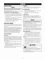
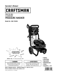
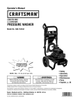
OIl Recommendations
We recommend the use of Briggs & Stratton Warranty
Certified oils for best performance. Other high-quality
detergent oils are acceptable if classified for service SF, SG,
SH, SJ or higher. DO NOT use special additives.
86
68 Z__
104
5o
32 _
eoi
_
,_
%_,
_1-__20
-4
-22
°
40
30
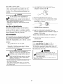
4.
l-r =-10
_'m
14
If needed,slowly pour oil into oil fill opening to the
"Full" mark on dipstick. DO NOT overfill.
Overfilling with oil may cause the engine to not start, or
hard starting.
DONOToverfill.
If overthe FULLmarkon dipstick,drainoil to reduceoil levelto
FULLmarkon dipstick.
oc
_
Checkoil level as described in Checking Oil Level
NOTICE
Outdoor temperatures determine the proper oil viscosity for
the engine. Use the chart to select the best viscosity for the
outdoor temperature range expected.
oF
2.
3.
_0
* Below40°F(4°0) the useof SAE30 will resultin hardstarting.
** Above80°F(27°0) the useof 10W30maycauseincreasedoil
consumption.Checkoil levelmorefrequently.
certification
markoil
and
API service
symbol API
with
NOTE:Synthetic
meeting
ILSACGF-2,
"SJ/CF ENERGYCONSERVING"or higher, is an
acceptable
oil at
all temperatures.
of synthetic oil
does not alter
required
oil change Use
intervals.
19
Replaceand tighten dipstick.
ChangingEngineOil
To servicethe air cleaner,fellow thesesteps:
Changeengine oil after the first 5 hours and every 50 hours
thereafter. If you are using your pressure washer under
extremely dirty or dusty conditions, or in extremely hot
weather, change oil more often.
1.
Loosen two screws (A) and lift off cover (B).
2.
Carefully remove air cleaner (C) from base (D).
3.
Install clean (or new) air cleaner in base. Air cleaner
must fit securely in base.
4.
Placecover over air cleaner and tighten screws.
CAUTION
Avoid prolonged or repeatedskin contact with used motor
oil.
Usedmotor oil hasbeenshownto causeskin cancerin certain
laboratoryanimals.
Thoroughlywashexposedareaswith soapandwater.
KEEPOUT OFREACHOFCHILDREN.DON'T
POLLUTE.CONSERVERESOURCES.RETURN
USEDOIL TO COLLECTIONCENTERS.
Changeoff while engine is still warm from running,as
follows:
1.
Drain fuel tank by running pressure washer until fuel
tank is empty.
2.
Disconnect spark plug wire and keep it away from spark
plug.
3.
Cleanarea around oil fill, remove oil fill cap/dipstick.
Wipe dipstick clean.
4.
Tip your pressure washer to drain oil from oil fill into a
suitable container making sure you tip your unit away
from spark plug. When crankcase is empty, return
pressure washer to upright position.
5.
Slowly pour recommended oil (about 20 oz.) into oil fill
opening. Pauseto permit oil to settle. Fill to "Full" mark
on dipstick.
6.
Wipe dipstick clean each time oil level is checked. DO
NOT overfill.
7.
Replaceand tighten dipstick.
8.
Wipe up any remaining oil.
9.
Reconnect spark plug wire to spark plug.
NOTE:You can purchase new air filter elements by calling
1-800-4-MY-HOIViE(469-4663).
Service Spark Plug
Service the spark plug every 100 hours of operation or
yearly, whichever occurs first.
1. Cleanarea around spark plug.
2.
Removeand inspect spark plug.
3.
Replacespark plug if electrodes are pitted, burned or
porcelain is cracked. Use the recommended replacement
plug. See Specifications.
4.
Checkelectrode gap with wire feeler gauge and set spark
plug gap to 0.020 inch (0.50 mm) if necessary.
5.
install spark plug and tighten firmly.
Service Air Cleaner
Your engine will not run properly and may be damagedif you
run it with a dirty air cleaner.
Service the air cleaner once every 25 hours of operation or
once eachyear, whichever comes first. Service more often if
operating under dirty or dusty conditions. Replacementsare
available at your local Sears service center.
NOTE:You can purchase a new spark plug by calling
1-OOO-44VlY-HOME
(469-4663).
Spark ArresterService
Your engine is not factory-equipped with a spark arrester, in
some areas, it is illegal to operatean engine without a spark
arrester. Check local laws and regulations. A spark arrester is
available from your nearest Sears service center. If you need
to order a spark arrester, please call 1-800-4-MY-HOME
(469-4663).
The spark arrester must be serviced every 50 hours to keep it
functioning as designed.
2O
If the engine has been running, the muffler will be very hot.
Allow the muffler to cool before servicing the spark arrester.
WARHIHG
AFTEREACHUSE
Water should not remain in the unit for long periods of time.
Sediments or minerals can deposit on pump parts and
"freeze" pump action. Follow these procedures after every
use:
s_
Contact with muffler area can result in serious
burns.
f_
structures
or damage
fuel
tankcombustibles,
causing a fire.
Exhaustheat/gases
can
ignite
* DONOTtouch hot partsandAVOIDhot exhaustgases.
* Allowequipmentto cool beforetouching.
* Keepat least5 feet (152cm) of clearanceon all sidesof
pressurewasherincludingoverhead.
* Codeof FederalRegulation(CFR)Title 36 Parks,Forests,and
PublicPropertyrequireequipmentpoweredby an internal
combustionengineto havea sparkarrester,maintainedin
effectiveworkingorder,complyingto USDAForestservice
standard5100-1Cor later revision.Inthe Stateof Californiaa
sparkarresteris requiredundersection4442 of the California
Publicresourcescode.Otherstatesmay havesimilar laws.
*
Removespark arrester screen for cleaningand inspection.
*
Replace if screen is damaged.
Air Cooling System
Overtime debris may accumulate in cylinder cooling fins and
cannot be observed without partial engine disassembly. For
this reason, we recommend you have a qualified Sears
service dealer clean the cooling system per recommended
intervals (see MaintenanceSchedule). Equally important is to
keeptop of engine free from debris. See CleanDebris.
1.
Shut off engine, turn off water supply, point gun in a
safe direction, press red button and squeezetrigger to
relieve trapped pressure and let engine cool.
WARHIHG
The high pressure stream of water that this
equipment produces can cut through skin and its
)ossible amputation.
nderlying tissues, leading to serious injury and
Spray gun traps high water pressure, even when
engine is stopped and water is disconnected,
which can cause injury.
* Keephigh pressurehoseconnectedto pumpand spraygun
whilesystemis pressurized.
* ALWAYSpointspraygun in safedirection,pressred button
and squeezespraygun triggerto releasehigh pressure,every
time youstop engine.
_
2.
Disconnect hose from spray gun and high pressure
outlet on pump. Drain water from hose, gun, and spray
tip extension. Use a rag to wipe off the hose.
3.
Empty pump of all pumped liquids by pulling recoil
handle about 6 times. This should remove most liquid in
pump.
4.
Ooil high pressure hose on hose wrap provided on
accessory tray.
5.
Store unit in a clean, dry area.
6.
If storing for more than 30 days see Long Term Storage
on next page.
WARHIHG
Fuel and its vapors are extremely flammable and
explosive.
death.
Fire or explosion can cause severe burns or
WHENSTORIN6FUELOREQUIPMENTWITH FUELIN TANK
* Storeawayfrom furnaces,stoves,water heaters,clothes
dryers,or otherappliancesthat havepilot light or otherignition
sourcebecausetheycanignitefuelvapors.
WINTERSTORAGE
ChangeOil
ty
While engine is still warm, drain oil from crankcase. Refill
with recommended grade. See ChangingEngine Oil.
NOTICE
ou must protect your unit from freezing temperatures.
Failureto do so will permanentlydamageyour pumpand
renderyour unit inoperable.
Freezedamageis not coveredunderwarranty.
Oil Cylinder Bore
To protect the unit from freezin9 temperatures:
1.
Follow steps 1-4 in the previous section After Each Use.
2.
Use pump saver, available at Sears retail item 6039, to
treat pump. This minimizes freeze damageand lubricates
pistons and seals.
3.
If pump saver is not available, connect a 3-foot section
of garden hose to water inlet adapter. Pour
RV-antifreeze (antifreeze without alcohol) into hose. Pull
recoil handle twice. Disconnect 3-foot hose.
4.
Store unit in a clean, dry area.
•
Removespark plug and pour about 1/2 ounce (15 m]) of
clean engine oil into the cylinder.
•
Install spark plug and pull starter handle slowly to
distribute oil.
Protect Pump
To protect the pump from damage caused by mineral
deposits or freezing, use PumpSaver, Model 6039, to treat
pump. This prevents freeze damageand lubricates pistons
and seals.
HOTICE
You must protect your unit from freezing temperatures.
LOHGTERM STORAGE
renderyour unit inoperable.
ailureto
do so will
permanently
damageyour pumpand
Freeze
damageis
not
coveredunderwarranty.
i
If you do not plan to use the pressure washer for more than
30 days, you must prepare the engine and pump for long
term storage.
NOTE:PumpSaver is available as an optional accessory. It is
not included with the pressure washer. Contact your local
Searsservice center to purchase PumpSaver.
It is important to prevent gum deposits from forming in
essential fuel system parts such as the carburetor, fuel filter,
fuel hose or tank during storage. Also, experience indicates
that alcohol-blended fuels (called gasohol, ethanol or
methanol) can attract moisture, which leads to separation
and formation of acids during storage. Acidic gas can
damagethe fuel system of an engine while in storage.
To use PumpSaver, make sure the pressure washer is turned
off and disconnected from supply water. Readand follow all
instructions and warnings given on the PumpSavercontainer.
Other Storage Tips
Protect Fuel System
1.
Clip the blue cap of PerfectMixTM siphon to wire form
bracket when siphon is not in a concentrate bottle.
2.
Store clear siphon tube by winding into about a 6 inch
loop and restrain with wire ties with paper sleeve.
FuelPreserver:
NOTE:Do not store clear siphon for long periods with kinks
in the tube.
1. DO NOTstore fuel from one season to another unless it
Fillthe fuel tank with fresh fuel allowing at least 1.5" of tank
space for fuel expansion as shown on page 8, when using a
fuel preserver cartridge with the fresh start fuel cap. If only
partially filled, air in the tank will promote fuel deterioration
during storage. Engine and fuel can be stored up to 6 months
with fuel preserver.
•
•
has been treated as described in Protect Fuel System.
2.
Check level of fuel preserver cartridge. Fuelpreserver is
dark in color.
Replacefuel container if it starts to rust. Rust and/or dirt
in fuel can cause problems if it's used with this unit.
Cover unit with a suitable protective cover that does not
retain moisture.
If cartridge is almost empty or empty, replacewith a new
fuel preservercartridge following the instructions in Fresh
StartTM FuelCapon page 9.
WARHIHG
If fuel preserver is not used, remove all fuel from tank and
run engine until it stops from lack of fuel.
_
Storagecovers can be flammable.
* DONOTplacea storagecoverovera hot pressurewasher.
* Letequipmentcoolfor a sufficienttime beforeplacingthe
coveron the equipment.
4.
22
Store unit in a clean and dry area.
Problem
Pump has followingproblems:
failure to producepressure,
erratic pressure, chattering, loss
of pressure, low water volume.
Detergentfails to mix with spray.
Cause
Correction
1.
Low pressure nozzle installed.
1.
Replacewith high pressure nozzle.
2.
Water inlet is blocked.
2.
Clearinlet.
3.
Inadequate water supply.
3.
Provide adequatewater flow.
4.
Inlet hose is kinked or leaking.
4.
Straighten inlet hose, patch leak.
5.
Clogged inlet hose strainer.
5.
Checkand clean inlet hose strainer.
6.
Water supply is over IO0°F.
6.
Provide cooler water supply.
7.
High pressure hose is blocked or
leaks.
7.
Clearblocks in high pressure hose or
replace hose.
8.
Gun leaks.
8.
Replacegun.
9.
Nozzleis obstructed.
9.
Cleannozzle.
10. Pump is faulty.
10. Contact Sears service facility
High pressure nozzle installed.
Replacewith low pressure nozzle.
Engine speed is too slow.
Move throttle control to FASTposition. If
engine still "bogs down", contact Sears
service facility.
1.
Dirty air cleaner.
1.
Cleanor replace air cleaner.
2.
Out of fuel.
2.
Fill fuel tank.
3.
Stale fuel.
3.
Drain fuel tank; fill with fresh fuel.
Spark plug wire not connected to
spark plug.
4.
Connectwire to spark plug.
5.
Bad spark plug.
5.
Replacespark plug.
6.
Water in fuel.
6.
Drain fuel tank; fill with fresh fuel.
7.
Excessively rich fuel mixture.
7.
Contact Sears service facility.
Engine runs good at no-load hut
"bogs" when load is added,
Enginewill not start; or starts and 4.
runsrough.
Engineshuts downduring
operation.
Out of fuel.
Fill fuel tank.
Engine lacks power.
Dirty air filter.
Replaceair filter.
23
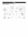
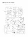
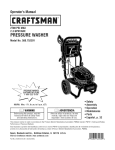
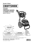
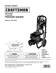
CRAFTSMAH3000 PSi Pressure Washer 580.752210
Main Unit _ ExpJodedView
\
\
900_
\
--5
24
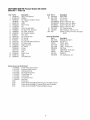
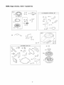
CRAFTSMAH3000 PSI Pressure Washer 580,752210
Main Unit -- Parts List
Item
1
2
3
4
5
6
7
8
9
10
11
12
13
14
15
16
17
18
19
20
21
Part #
205961GS
B204257GS
205963GS
195964GS
205291GS
198164GS
23139DGS
194298GS
190588GS
190589GS
190593GS
B2384GS
189971GS
205910GS
B2203GS
192131GS
205912GS
204658GS
205964GS
192050GS
200517GS
205413GS
204684GS
204627GS
200595GS
Item Part #
Description
22 204484GS
WIREFORM
23 205710GS
KIT, Nozzles
198841GS
Nozzle,Soap
201580AWGS Nozzle,Project Pro, Cyn
201580AXGS Nozzle,Project Pro, Mgnta
201580XGS Nozzle,Project Pro, Orng
201580AAGS Nozzle,Project Pro, Red
24 192310GS
KIT, Vibration Mount
25 75246GS
HHS,Trilobular, 3/8-16 x 1-1/4
900 NSP
ENGINE(12S512-0119-B1) (see pages
26-29)
Description
BASE,wNib Mounts
HANDLE
KIT, Billboard w/Clips & Decals
Clips, Tree
HOSE
ASSY, Pump
Key
Valve, Thermal Relief
Kit, Water Inlet, Anodized
Kit, Outlet, Anodized
Kit, Chemical Injection
Filter, inlet
Kit, Chemical Hose
KIT, Handle
KIT, Handle
KIT, Pump Mounting Hardware
KIT, Rope Guide
HOSE,Chemical
KIT, Wheel
E-Ring
Hubcap
Axle
WRAP, Hose
GUN
EXTENSION,QC
Items Net Illustrated
Part #
205712GS
AB3061BGS
792342
202712GS
202713GS
189332GS
100092
794693
87815GS
194256GS
Optional Accessories Not Illustrated
7175187GS
7175197GS
7175124GS
7175122GS
7175116GS
7175129GS
7175121GS
7174402GS
6039
6159
6160
6161
Garden Hose Quick Connect
Accessory Quick Connect
Rotating Brush Kit
30' Replacement Hose
0 Ring Repair Kit
Turbo Nozzle
25' Extension Hose
Hose Reel
Pump Saver
Project Pro® PerfectMWMMulti-Purpose and Vehicle Cleaner
Project Pro® PerfectMWMConcrete, Brick, and Tile Cleaner
Project Pro® PerfectMWMMold and Mildew Cleaner
25
Description
MANUAL, Operator's
OIL BOTTLE
COVER,Static
DECAL,Recoil
LABEL,Torquepower
CAP, Plug
CARTRIDGE,Fresh Start
LABEL,Warning
GOGGLES
KIT, Tag/Warning, Srv
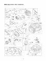
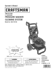
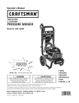
EHGIHE, Briggs & Stratto.,
12S512 - Exploded View
1022
51
51A_
993
1029
883
7
10'_
3@
830
%
914 ¢_
1227 I
10231 1022
615 0
404 (_
718
[
5o5®
616
251
27o
-__
24
32_
1102
741
1095 VALVEGASKETSET
7 _022__
51A_
51
51B_
993_
15® 2o_
26
EHGIHE, BrJggs& Stratto.,
12S512 - ExpJodedView
621
692
365
51A
108
51B
137 __
163
188
276
127
95
51
425
968
613 _
%
443
259
967
957
163
287 _
445
19o
977 CARBURETOR
GASKETSET
276 _
51A
633 _;_
163
524
51B_
27
51
633A Q
EHGIHE, BrJggs& Stratto.,
12S512 - ExpJodedView
65
121 CARBURETOR
OVERHAULKIT
58
55
592 ®
104 _,
276
51
633 ©5
60
121__
,
134
633A
689 o
51B
456 @
51A
597
127
137
163
356
37
78
305
358 ENGINEGASKETSET
332
868
455 _
_<LY
883 _
1005
IC
163
51A
524
28
ENGINE, 8riggs & Stratton, 12S512 - Parts List
Item
1
2
3
4
5
7
8
9
10
11
11A
12
13
15
16
20
22
23
24
25
26
27
28
29
32
32A
33
34
35
36
37
40
43
45
46
51
51A
51B
55
58
60
65
78
95
97
104
108
109
117
118
121
122
125
127
130
133
134
137
163
187
188
190
192
202
209
222
227
238
259
276
287
300
304
305
306
307
Part #
697893
399269
299819S
498983
792381
697230
495786
699833
691125
691260
692937
692232
691137
691680
691457
399781S
691092
790116
222698S
791968
791326
791969
791324
691866
499423
499424
691664
695759
499642
499641
691304
691304
694086
692194
691997
690977
694039
692668
697735
692555
691421
691921
281434S
690837
691108
691636
499682
691242
691182
499681
497466
792383
792383
792382
698055
694468
691203
398187
398188
693981
691894
791766
691147
690940
694543
691303
691290
792397
690783
691300
691189
271716
690940
697590
499676
691108
691232
690345
Description
Cylinder Assembly
Kit-Bushing/Seal (Magneto Side)
£ Seal-Oil (Magneto Side)
Sump-Engine
Bead-Cylinder
£ 1 Gasket-Cylinder Head
Breather Assembly
£ Gasket-Breather
Screw (Breather Assembly)
Tube-Breather
Tube-Breather
£ Gasket-Crankcase
Screw (Cylinder Head)
Plug-Oil Drain
Crankshaft
£ Seal-Oil (PTO Side)
Screw (Engine Sump)
Flywheel
Key-Flywheel
Piston Assembly (Standard)
Piston Assembly (.020" Oversize)
Ring Set (Standard)
Ring Set (.020" Oversize)
Lock-Piston Pin
Pin-Piston
Rod-Connecting
Screw (Connecting Rod)
Screw (Connecting Rod)
Valve-Exhaust
Valve-Intake
Spring-Valve (Intake)
Spring-Valve (Exhaust)
Guard-Flywheel
Retainer-Valve
Slinger-Governor/Oil
Tappet-Valve
Camshaft
¥ £ 1:1 Gasket-Intake
¥ £ :i:1 Gasket-intake
¥ £ :i:1 Gasket-Intake
Housing-Rewind Starter
Rope-Starter (Cut to Required Length)
Grip-Starter Rope
Screw (Rewind Starter)
Screw (Flywheel Guard)
Screw (Throttle Valve)
Shaft-Throttle
¥ Pin-Float Hinge
Valve-Choke
Shaft-Choke
Jet-Main (Standard)
Jet-Main (High Altitude)
Kit-Carburetor Overhaul
Spacer-Carburetor
Carburetor
¥ Plug-Welch
Valve-Throttle
Float-Carburetor
¥ Kit-Needle/Seat
¥ :i:Gasket-Float Bowl
¥ £ :i:1 Gasket-Air Cleaner
Line-Fuel (Cut to Required Length)
Screw (Control Bracket)
Screw (Fuel Tank)
Bali-Rocker Arm
Link-Mechanical Governor
Spring-Governor
Bracket-Control
Lever-Governor Control
Cap-Valve
Bracket-Casing Clamp
¥ :i:Washer-Sealing
Screw (Dipstick Tube)
Muffler
Housing-Blower
Screw (Blower Housing)
Shield-Cylinder
Screw (Cylinder Shield)
Item
332
333
334
337
356
358
363
365
404
425
443
445
455
456
459
505
523
524
525
562
584
585
592
597
601
608
613
613A
615
616
619
621
633
633A
635
67O
684
689
692
718
741
83O
832
836
836A
842
843
847
851
868
883
886
914
914A
Part #
690662
802574
691061
692051
692390
792384
19069
691129
690272
690244
690255
697029
791960
692299
281505S
691251
499621
692296
495265
691119
697734
691879
690800
691696
791850
497680
691108
691140
690340
698801
691108
692310
693867
691321
66538S
692294
690345
691855
690572
690959
790345
694544
691466
Description
Nut (Flywheel)
Armature-Magneto
Screw (Magneto Armature)
Plug-Spark
Wire-Stop
Gasket Set-Engine
Puller-Flywheel
Screw (Carburetor)
Washer (Governor Crank)
Screw (Air CleanerCover)
Screw (Air Cleaner Primer Base)
Filter-Air CleanerCartridge
Cup-Flywheel
Retainer-Spring
Plate-Pawl Friction
Nut (Governor Control Lever)
Dipstick
£ Seal-O Ring (Dipstick)
Dipstick Tube
Bolt (Governor Control Lever)
Cover-Breather Passage
£ Gasket-Breather Passage
Nut (Rewind Starter)
Screw (Pawl Friction Plate)
Clamp-Hose
Starter-Rewind
Screw (Muffler)
Screw (Muffler)
Retainer-Governor Shaft
Crank-Governor
Screw (Cylinder Head Plate)
Switch-Stop
¥ :I: Seal-Choke/Throttle Shaft
¥ $ Seal-Choke/Throttle Shaft
Boot-Spark Plug
Spacer-Fuel Tank
Screw (Breather Passage Cover)
Spring-Friction
Spring-Detent
Pin-Locating
Gear-Timing
Stud-Rocker Arm
Guard-Muffler
691147
697551
691031
691884
692047
493880S
692044
691893
696268
691108
691127
957
966
967
968
972
975
977
993
1005
1022
1023
1026
1029
1034
1059
1095
1102
1210
1211
£
¥
793606
690243
273356
691342
699374
493640
792385
694088
691346
691890
499624
692045
691230
691343
692311
792386
691255
498144
498144
Included in
Included in
Included in
Included in
Screw (Muffler Guard)
Screw (Muffler Guard)
£ Seal-O Ring (Dipstick Tube)
Lever-Sleeve
Dipstick/Tube Assembly
Terminal-Spark Plug
£ 1 Seal-Valve
£ 1 Gasket-Exhaust
Gasket Kit-Cylinder Head/Plate
Screw (Rocker Cover)
Screw (Rocker Cover)(Assemble in Number 1 and
Number 2 Positions)
Cap-FuelTank
Base-Air CleanerPrimer
Filter-Pre Cleaner
Cover-Air Cleaner
Tank-Fuel
Bowl-Float
Gasket Set-Carburetor
£ 1 Gasket-Cylinder Head Plate
Fan-Flywheel
£ 1 Gasket-Rocker Cover
Cover-Rocker
Rod-Push
Rocker Arm
Guide-Push Rod
Kit-Screw/Washer
Gasket Set-Valve
Pilot-Guide
Pulley/Spring Assembly (Pulley)
Pulley/Spring Assembly (Spring)
Engine Gasket Set, Item No. 358
Carburetor Overhaul Kit, Item No. 121
Carburetor Gasket Set, Item No. 977
Valve Gasket Set, Item No. 1095
t
t
29
Sears, Roebuck and Co., U.S.A. (Sears), the Cafifornia Air Resources Board (CARD) and
the United States Environmental Protection Agency (UoSoEPA)
Emissions Control System Warranty Statement
(Owner's Defect Warranty Rights and Obfigations}
The California Air Resources Board (CARD), U.S. EPA and Sears are
pleased to explain the Emissions Control System Warranty on your
small offroad engine (SORE).In California, new small offroad
engines model year 2006 and later must be designed, built and
equipped to meet the State's stringent anti-smog standards.
Elsewherein the United States, new non-road,spark-ignition engines
certified for model year 1997 and later must meet similar standardsset
forth bythe U.S.EPA.Sears must warrant the emissions control
system on your engine for the periodsof time listed below, provided
there has beenno abuse, neglector improper maintenanceof your
small off-road engine.
Your emissions control system includes parts such as the
carburetor, air cleaner, ignition system, fuel line, muffler and
catalytic converter. Also included may be connectors and other
emissions related assemblies.
*
*
*
*
*
b. Air Induction System
* Air cleaner
* Intake manifold
*
c.
*
*
d.
*
*
*
e.
*
Where a warrantable condition exists, Sears will repair your small
off-road engine at no cost to you including diagnosis, parts and
labor.
Sears, Roebuck and Co. Emissions Control Defects Warranty
Coverage
Small off-road engines are \warrantedrelative to emissions control
parts defects for a period of two years, subject to provisions set
forth below. If any covered part on your engine is defective,the part
will be repaired or replaced by Sears.
Owner's Warranty Responsibilities
As the small off-road engine owner, you are responsible for the
performance of the required maintenance listed in your Operating
and Maintenance Instructions. Sears recommends that you retain all
your receipts covering maintenance on your small off-road engine,
but Sears cannot deny warranty solely for the lack of receipts or for
your failure to ensurethe performance of all scheduled maintenance.
As the small off-road engine owner, you should however be aware
that Sears may deny you warranty coverage if your small off-road
engine or a part has failed due to abuse, neglect, improper
maintenance or unapproved modifications.
You are responsible for presenting your small off-road engine to an
Authorized Sears Service Dealeras soon as a problem exists.
The undisputed warranty repairs should be completed in a
reasonable amount of time, not to exceed30 days.
If you have any questions regarding your warranty rights and
responsibilities, you should contact a Sears Service Representative
at 1-800-469-4663.
Carburetor and internal parts
Fuel Pump
Fuelline, fuel line fittings, clamps
Fueltank, cap and tether
Carbon canister
2.
3.
4.
5.
Purge and vent line
Ignition System
Spark plug(s)
Magneto ignition system
Catalyst System
Catalytic converter
Exhaust manifold
Air injection system, Pulse valve
Miscellaneous Items
Vacuum, temperature, position, time sensitive valves and
switches
* Connectors and assemblies
Lengthof Coverage
Sears\warrantsto the initial owner and eachsubsequent
purchaser that the Warranted Parts shall be free from defects in
materials and workmanship which caused the failure of the
Warranted Parts for a period of two years from the date the
engine is deliveredto a retail purchaser.
No Charge
Repair or replacement of any Warranted Part will be performed
at no charge to the owner, including diagnostic labor which
leads to the determination that a Warranted Part is defective, if
the diagnostic work is performed at an Authorized Sears
Service Dealer.
Claims and Coverage Exclusions
Warranty claims shall be filed in accordance with the provisions
of the Sears Engine Warranty Policy. Warranty coverage shall
be excluded for failures of Warranted Parts which are not
original Sears parts or becauseof abuse, neglect or improper
maintenance as set forth in the Sears Engine Warranty Policy.
Sears is not liable to cover failures of Warranted Parts caused
by the use of add-on, non-original, or modified parts.
Maintenance
Any Warranted Part \which is not scheduled for replacement as
required maintenanceor which is scheduled only for regular
inspection to the effect of "repair or replaceas necessary"shall
be warranted asto defects for the warranty period. Any
Warranted Part which is scheduledfor replacementas required
maintenanceshall be warranted as to defects only for the period
of time up to the first scheduled replacementfor that part. Any
replacement part that is equivalent in performance and durability
may be used in the performance of any maintenanceor repairs.
The owner is responsible for the performance of all required
maintenance,as defined in the Sears Operating and Maintenance
Instructions.
6. Consequential Coverage
Coverage hereunder shall extend to the failure of any engine
components caused by the failure of any Warranted Part still
under warranty.
The emissions warranty is a defects warranty. Defects are judged
on normal engine performance. The warranty is not related to an inuse emissions test.
Sears, Roebuck and Co. Emissions Control Defects Warranty
Provisions
The following are specific provisions relative to your Emissions
Control Defects Warranty Coverage.It is in addition to the Sears
engine warranty for non-regulated engines found in the Operating and
Maintenance Instructions.
1. Warranted Parts
Coverageunder this warranty extends only to the parts listed
below (the emissions control systems parts) to the extent these
parts were present on the engine purchased.
a. Fuel Metering System
* Cold start enrichment system
In the USAandCanada,a 24-hour hotline,1-890-469-4663,hasa menuof pre-recordedmessagesofferingyou productmaintenance
information.
3O
Emission information
Certain engines will be certified to meet the United States
Environmental Protection Agency (USEPA)Phase 2 emission
standards. For phase 2 certified engines, the Emissions
Compliance Period referred to on the Emissions Compliance
label indicates the number of operating hours for which the
engine has been shown to meet Federalemission
requirements.
Enginesthat are certified to meet the California Air Resources
Board (CARB) Emission Standards must display information
regarding the Emissions Durability Period and Air Index. The
engine manufacturer makesthis information availableto the
consumer on emission labels. The engine emission label will
indicate certification information.
For engines less than 225 cc displacement:
CategoryC = 125 hours
Category B = 250 hours
CategoryA = 500 hours.
The Emissions DurabilityPeriod describes the number of
hours of actual running time for which the engine is certified
to be emissions compliant, assuming proper maintenancein
accordancewith the Operating & Maintenance Instructions.
The following categories are used:
For engines of 225 cc or more displacement:
CategoryC = 250 hours
Category B = 500 hours
CategoryA = 1000 hours.
Moderate: Engine is certified to be emission compliant for
125 hours of actual engine running time.
Intermediate: Engine is certified to be emission compliant
for 250 hours of actual engine running time.
Extended: Engine is certified to be emission compliant for
500 hours of actual engine running time.
Forexample, a typical walk-behind lawn mower is used 20 to
25 hours per year. Therefore, the Emissions Durability
Period of an engine with an intermediate rating would
equateto 10 to 12 years.
31
GARANTIA ..........................................
REGLASDE SEGURIDAD ............................
32
MANTENIMIENTO ..................................
32-35
CARACTERiSTICASY CONTROLES.......................
47-51
ALMACENAMIENTO ...................................
52
36
REPARACIONDE DANOSREPUESTOS ....................
53
MONTAJE ........................................
37-40
GARANTIADEL CONTROLDE EMISIONES ...............
54-55
OPERACION.......................................
41-45
COMOORDENARPARTES ...............
ESPECIFICACIONES...................................
PAGINAPOSTERIOR
46
Oarant[a completa de un afio de la fimpiadora a presi_n Craftsman
Si la limpiadora a presi6n falla debido a defectos de materiales o mane de obra en el plazo de un a_o a partir de la fecha de compra,
devu61valaa cualquier almac_n Sears, punto de venta de Craftsman o centre de reparaci6n y repuestos de Sears de los Estados Unidos o
Canada.para su reparaci6n gratuita o, en case de que _sta no sea posible, para su sustituci6n.
El periodo de garantia se reducir_ a 90 dias desde la fecha de compra si la limpiadora a presi6n se utiliza en algL]nmemento con fines
comerciales o de alquiler.
Esta garantia le otorga determinados derechos legales yes posible que tonga otros derechos que pueden variar de un pais o estado a otro.
Sears, Roebuck and Co., Dept. 817 WA, Hoffman Estates, IL 68179
Sears Canada inc., Toronto, Ontario, Canada IVl5B 288
,_
personal.
Este es elSigs
simhelo
Iss instruccionesde
de alerts de seguridsd.
redes los
Esussde
menssjes
pars
deindicsrle
seguridsdque
situscienescon
spsrecen despues
peligros de
potencislesde
este simhoio lesion
pars evitsr
pars elpesihies
JesieBes
e mgerte.
SimboJosde PeJigroy Significados
/I[__
T_-I-'_
!-JL
ea este
manual
minuciessmente
y conozcss
fende Iss
...................
psrtes
y el
funcionsmientode
su m_quins
limpisders
s
presi6n. Cenezcs sue splicsciones, sue limitscionesy los
peligros involucrsdos.
El simbolo de alerta de seguridad (_iiL) es usado con una palabra
(PELIGRO,ADVERTENCIA,PRECAUCION),un mensajepor escrito o
una ilustraciOn, para alertarlo acerca de cualquier situaciOnde
GasesT6xicos
OuimicoPeligroso
2
peligro que pueda existir. PELIGROindica un riesgo el cual, si no se
evita, causar_ la muerte o una heridagrave. ADVERTENCIAindica un
riesgo el cual, si no se evita, puedecausar la muerte o una herida
grave. PRECAUCIONindica un riesgo, el cual, si no se evita, puede
causar heridas menores o moderadas. AVISOindica una situaci6n
DescargaEl_ctrica
%
SuperficiesResbalosas
Caer
Inyecci6nLiquida
que podria resultar en el da_o del equipo. Siga los mensajesde
seguridad para evitar o reducir los riesgos de heridas e inclusive la
muerte.
Partesen Movimiento
Fuego
32
Objetos Voladores
Explosi6n
SuperficieCaliente
ManualdelOperario
Contragolpe
ADVERTENCIA
ADVERTENCIA
El escape del motor de este preducto contiene eiementos
quimicos recenocidos en el Estado de California
per producir
c_ncer,defectos de nacimiento
La. gasolina y sus vapores son extremadamente
inflamables y explosivos.
g otros danes de ripe reproductive.
severas e inclusive la muerte.
El fuego o una explosi6n pueden causar quemaduras
PELIGRO
S_-Contenido
es NOCIVO O
CUANDO ANABA COMBUSTIBLE 0 VACiE EL DEPOSITO
AL EN CASO
• Apague el limpiadora a presi6n (posici6n OFF)y d_jelo enfriar al menos
por 2 minutos antes de remover la tapa de la combustible. Afloje la
tapa lentamente para dejar que la presi6n salga del tanque.
ojos, la piel o la
ropa, No tomar internamente. Evite respirarla niebla o
el vapor, La exposici6nexcesiva de los ojos o la piel
puedecausar irritaciOn. Mantengael estabilizador fuera
<<<<<-_-<<_
INGERIDO. Evite el contacto con los
• Llene o vacie el dep6sito de combustible a la intemperie.
del alcance de los ni_os.
• NO Ilene demasiado el tanque. Permita al menos espacio para la
expansi6n del combustible.
Elestabilizador
decombustibleesun quimicopeligroso.**
• Si se ha derramado combustible, espere a que se evapore antes de
arrancar el motor.
La tapa de combustible FreshStartTM esta diseiiada para sostener un
cartucho el cual contiene el estabilizador de combustible.
• Mantenga la gasolina alejada de chispas, llamas abiertas, pilotos, calor
y otras fuentes de ignici6n.
EN CASO DE SERINGERIDO,Ilame un medico inmediatamente. No
induzca el v6mito. En caso de inhalaci6n salir al aire libre. En caso de
contacto con los ojos o con la piel, lavar abundantemente con agua
durante 15 minutos.
• NO encienda un cigarrillo o fume.
CUANBOPONGA
ENFUNCIONAMIENTO
ELEQUIPO
Almacene los cartuchos sin abrir en un area fresca, seca y bien
ventilada. Mantenga el cartucho abierto en latapa de combustible, y la
tapa de combustible cerrada en el tanque de combustible cuando no
estd en uso.
• Compruebe que la bujia, el silenciador, el tap6n del dep6sito de
combustible y el filtro de aire estan instalados.
En caso de la emergencia, contacte a un m_dico inmediatamente y llama
1-800-424-9300 para la informaci6n material de la seguridad.
CUANDO OPERE EL EQUIPO
• NO arranque el motor sin la bujia instalada.
• NO incline el motor o el equipo, de tal manera que la gasolina se pueda
derramar.
*El estabilizadorde combustiblecontiene2,6-di-tert-butilfenol(128-39-2)y
destiladodepetr61eoalif_tico(64742-47-8).
• NO rocie liquidos inflamables.
CUANBO TRANSPORTE 0 REPARE EL EQUIPO
ADVERTENCIA
AI motor funcionar,
se produce mon6xido
• Transporte o repare el equipo con el tanque de combustible vacio, o
con la valvula para apagar el combustible, apagada (posici6n OFF).
de carbono,
un gas inodoro y venenoso.
Respirar mon6xido
• Desconecte el cable de la bujia.
de carbono puede provocar dolor
CUANBO ALMACENE 0 GUARBE EL EQUIPO CON COMBUSTIBLE
EN EL TANQUE
de cabeza,n_useas,
fatiga, mareos,
confusi6n,
ataques,
desmayosv6mitos,
o incluso
la muerte.
• Almacene alejado de calderas, estufas, calentadores de agua, secadoras
de ropa u otros aparatos electrodomdsticos que posean pilotos u otras
fuentes de ignici6n, porque ellos puedenencender los vapores de la
combustible.
Algunas sustancias quimicas o los detergentes pueden
ser perjudiciales si inhalados o ingeridos, causando la
n_.usea severa, desmayando
o para envenenar.
• Opere el limpiadora a presi6n SOLAMENTEal aire libre.
• AsegQresede que los gases de escape no puedan entrar por ventanas,
puertas, tomas de aire de ventilaci6n u otras aberturas en un espacio
cerrado en el que puedan acumularse.
ADVERTENCIA
• NO arranque ni deje funoionar el motor en interiores ni en zonas
cerradas, aunque haya ventanas y puertas abiertas.
_¢
• Utilice un respirador o mascara siempre que exista la posibilidad de
inhalar vapores.
Eliesgode
contacto
con los cablesel_ctricospuedeprovocar
electrocuci6n.
electrocuciOn
y quemaduras.
• NUNCA rode cerca de una fuente de energia el_ctrica.
• Lea todas las instrucciones de la mascara para asegurarse de que le
brindard la protecci6n necesaria contra la inhalaci6n de vapores
nocivos.
33
ADVERTEHCIA
_,k,=
ADVERTEHCIA
El retroceso (repliegue r_.pido) del cable del arrancador
El chorro de agua a alta presi6n que este equipo
puede producir
produce,puedeatravesar
lesiones. El retroceso impedir_ que el
usuario suelte el cable a tiempo y tirar_, de su mano y
brazo hacia el motor.
Como resultado, podrian producirse
contusiones o esguinces.
_
fracturas,
• NUNCAtire del cable del arrancador sin eliminar previamente la presi6n
de la pistola rociadora.
la
piely
los
tejidos
_odrian dar lugar a la amputaciOn
de un miembro.
ubcut_.neos, provocando lesiones de gravedad que
La pistola rociadora contiene agua a alta presi6n incluso
con el motor parado y el agua desconectada, que puede
causar la herida.
• NO permita en ning_n momento que NINOS operen la m_quina
• Cuando arranque el motor, tire lentamente del cable basrasentir una
resistencia y, a continuaci6n, tire r@idamente de 81para evitar su
retroceso.
limpiadora a presi6n.
• NUNCA repare la manguera de alta presi6n. Remplacela.
• NUNCA utilice ning_n tipo de sellador para reparar una fuga en una
conexi6n. Sustituya la junta tOrica o la junta.
• Despuds que cada tentativa que empieza, donde motor falla de correr,
siempre se_alar el fusil en la direcci6n segura,presione el seguro
(bot6n rojo) y el disparador del fusil del rocio del estruj6n para liberar
la presi6n alta.
• NUNCA conecte la manguera de alta presi6n al prolongador de la
boquilla.
• Mantenga conectada la manguera a la m_quina o a la pistola de rociado
cuando el sistema est_ presurizado.
• Sujete firmemente la pistola rociadora con ambas manos cuando
aplique un rociado a alta presi6n para evitar lesiones cuando se
produzca el retroceso de la pistola.
• SIEMPRE que pare el motor, apunte con la pistola rociadora hacia una
direcci6n segura Presione el seguro (botOn rojo) y apriete el gatillo
para descargar la presiOny evitar el retroceso.
ADVERTEHCIA
• NUNCA apunte la pistola a la gente, animales o plantas.
• NO fije la pistola rociadora en la posici6n abierta.
El uso de limpiadora a presi6n puede crear los charcos
y superficies
• NO abandone la pistola rociadora cuando la mgquina estd en
funcionamiento.
resbalosas.
• NUNCA utilice una pistola rociadora cuyo seguro o protecci6n para el
gatillo no est6 en perfecto estado de funcionamiento.
caidas.
El retroceso de la pistola rociadora puede provocar
• Aseg_rese en todo momento de conectar correctamente la pistola
rociadora, las boquillas y los accesorios.
• Utilice la limpiadora a presi6n desde una superficie estable.
• El area de limpieza deber;i tener inclinaciones y drenajes adecuados
para disminuir la posibilidad de caidas debido a superficies resbalosas.
ADVERTENCJA
• Extreme las precauciones si necesita utilizar la limpiadora a presi6n
desde una escalera, un andamio u otro lugar similar.
• Sujete firmemente la pistola rociadora con ambas manos cuando
aplique un rociado a alta presi6n para evitar lesiones cuando se
produzca el retroceso de la pistola.
"_
_¢
ADVERTEHCIA
Chispear involuntario
puede tener corno resultado el
fuegoo el golpe el_ctrico.
CUANDO
AJUSTE
0 HAGAREPARACIONES
A SUIVI._QUINA
LIMPIADORA A PRESION
El contacto con
la zona del silenciador puede producir
quemaduras
graves.
• Siempre desconecte el alambre de la bujia y col6quelo donde no pueda
entrar en contacto con la bujia.
Los gasesy el calor de escapepueden inflamar los
_
CUANDO PRUEBE LA BUJIA DEL MOTOR
ateriales combustibles y las estructuras o da_ar el
dep6sito de combustible y provocar un incendio.
• Utilice un comprobador de bujias homologado.
• NO comprueba la chispa sin la bujia instalada.
• NO toque las superficies calientes y EVITE los gases del escape a alta
temperatura.
• Permita que el equipo se enfrie antes de tocarlo.
• Deje un espacio minimo de 152 cm (5 pies) alrededor del limpiadora a
presi6n, incluida la parte superior.
• El C6digo de Normativa Federal (CFR,Titulo 36: Parques, Bosques y
Propiedad P_blica) obliga a instalar una pantalla apagachispas en los
equipos con motor de combusti6n interno y a mantenerla en buenas
condiciones de funcionamiento, conforme a la norma 5100-1C (o
posterior) del Servicio Forestal de la USDA. Enel Estado de California.
la ley exige el uso de una pantalla apagachispas (Secci6n 4442 del
C6digo de Recursos Pt_blicosde California). En otros estados puede
haber leyes similares en vigor.
34
AVISO
ADVERTEHCIA
El rociado de alta presi6n puede daffar elementos fr_.giles,
incluyendoel vidrio.
El arrancador
las
manos, el ypelo,
otrasla piezas
ropa, 0que
los rotan
accesorios.
pueden enredar
NO dirija la pistola rociadora hacia un cristal cuando utilice la boquilla
MAX (punta de alfiler).
• NUNCA utilice la limpiadora a presi6n sin sus carcasas o tapas de
protecci6n.
NUNCA apunte la pistola a plantas.
• NO use ropa suelta, joyas o elementos que puedan quedar atrapados en
el arranque o en otras partes rotatorias.
AVISO
• Ate para arriba el pelo largo y quite la joyeria.
El tratamiento
inadecuado del limpiadora
a presi6n puede daffarlo
acortar su vida productiva.
ADVERTENCIA
•
si usted tiene alguna pregunta acerca de las finalidades de uso del
generador, preg0ntele a su concesionario o contacte a Sears.
NUNCA deber_n ser operadas las unidades con partes rotas o ausentes
o sin la caja o cubiertas de protecci6n.
Riesgo de lesiones oculares.
El agua rociada puede salpicar 0 propulsar objetos.
NO eluda ningt_n dispositivo de seguridad de esta mdquina.
NO intente alterar la velocidad controlada,
• Utilice siempre galas de protecci6n cuando utilice este equipo o si se
encuentra cerca de donde se est9 utilizando.
NO utilice la limpiadora a presi6n por encima de su presi6n nominal.
NO haga ninguna modificaci6n en la limpiadora a presi6n.
• Antes de poner en marcha la limpiadora a presi6n, asegQresede Ilevar
gafas de protecci6n adecuadas.
Antes de poner en marcha la m_iquina limpiadora a presi6n en clima
frio, revise todas las partes del equipo y aseg0rese de que no se haya
formado hielo sobre elias.
• Utilice SlEMPRE las galas de seguridad apropiadas.
NUNCA mueva la m_iquina halando la manguera de alta presi6n. Utilice
la manija que viene con la unidad.
Revise que el sistema de combustible no presente fugas o signos de
deterioro, como mangueras desgastadas o porosas, sujetadores flojos
o ausentes, tapa o tanque daiiados. Corrija todos los defectos antes de
operar la m_iquina limpiadora a presi6n.
El equipo de alta presi6n est,1diseiiado para ser utilizado UNICAMENTE
con las partes autorizadas Sears. Si utiliza este equipo con partes que
no cumplan con las especificaciones minimas, el usuario asume todos
los riesgos y responsabilidades.
35
CONOZCASU MAQUJHASISTEMADE LIMPJEZA
!i _!i_!i] Lea
el IVlanualdel
Operarioy
inssistema
regias de
de poneren
marcha
su sistema
I.................
Compare
Ins ilustraciones
con su
de seguridadantes
limpieza para familiarizarse
con
Ins ubicaciones
dede
loslimpieza.
diferentes controles y ajustes.
Guarde este manual para referencias futuras.
iii
IVl- Soporteparabotella:La botellade soluciSnlimpiadorase
colocaen el soportede alambre,
A - Pistola de Rociado -- Controla la aplicaciSn de agua sobre la
superficie de limpieza con el gatillo. Incluye cerrojo de
seguridad.
N- ExtensiSn
paraBoquillasconConexiSnR_pida-- Le permite
usarquatropuntasde rociadodiferentes.
B - Pantas de Rosiado - Detergente,0°, 15° y 40°: para diferentes
alta presiSn aplicaciones de limpieza.
P - Tapadel Dep6sitodel Aeeite-- Lleneel motor conaceiteaquL
Q- Mangaerade Alia Presi6n-- La abrazadera
de la manguera
facilitael transportey manejode la manguerade altapresi6n.
Conecteun extremode la mangueraa la bombade aguay el
otro a la pistolarociadora.
C - Bandeja de Accesorios - Permite almacenar cOmodamentelos
accesorios de serie.
B - Arrancador de Retroceso -- Usado para arrancar el motor
manualmente.
R- Asaplegable-- El asay la bandejade accesoriossepliegan
sobreel motor cuandoestAfifo parareducirel espacio
necesarioparael almacena-miento.
S- ProjectPro_'PerfectMW
M-- Unade eliasest,.conectadaal
dep6sitode limpieza,y la otrase utilizapara inyectar
detergentesaptosparala limpiadoraa presi6ndesdeuna
botellau otro recipiente.
Nomostrado:
E - Tanque del Combustible -- Lleneel tanque con gasolina regular
sin contenido de plomo en este punto. Siempre habitaciSnde hoja
para la expansiSndel combustible.
F - Filtro de Aire -- El elemento de filtro tipo seco limita la cantidad
de suciedady polvo que se introduce en el motor.
G - Paianca de Controlde la V;_ivniade ReguiaciSn-- Coloca el
motor en modo de arranque para el arrancador de retrocesoy
detiene el motor en funcionamiento.
CaicomaniaEjempiarde Dates(el traserocercanode plato
despreciaNe)
-- Proporcionael modeloy el nt]merode seriede
limpiadoraa presi6n.Tengapor favor estosprontamentedisponible
cu_.ndoIlamarparala ayuda.
EtiqaetadeAdvertensia
e Instrusciones
-- Identificalosriesgose
indicael procedimiento
adecuado
de puestaen marchao de parada
dela limpiadoraa presiSn.
H - Bomha -- Desarrolla alta presiSn de agua.
J - Autom_tico se Enfria Sistema -- Los ciclos regan por bomba
cuando agua alcanza 125°-155°F. Entibiar agua descargar_ de la
bomba en el suelo. Este sistema previene el da_o interno de
bomba.
K - Toma de Alia PresiSn-- ConexiSn para la manguera de alta
presiSn.
Gafasde Seguridad-- Siempreuselasgafasencerradascuando
corrersu limpiadoraa presiSn.
L- EntradadeAgna-- ConexiOnpara la manguerade jardin.
36
Su sistema de limpieza requiere de cierto ensamble y estar_ lista
para ser usado Onicamentedespu_s de haber depositado el
combustible y el aceite recomendado.
Si tiene prohlemas conel ensamhle de su m;_quina limpiadera a
presiOn,Ilame a la linea de ayuda de la m_quina limpiadora a
presiOnal 1-800-222-3136.
Saque todo el contenido de la caja de carton, a excepciOnde la
limpiadora a presiOn.
2.
Abra completamente la caja de carton cortando cada una de
sus esquinas de arriba abajo.
3.
Saque la limpiadora a presiOnde la caja de carton.
Conecte manguera a alta presiOna pistola rociadoray a bomba.
Conecte el suministro de agua a bomba.
8.
Conecte boquilla la extension al pistola rociadora.
9.
Seleccione una boquilla PrecisionSprayTM con conector rApido
y con_ctela al prolongador de la boquilla.
Conecte el IVlanubrio y bandeja accesoria
gesembale la Limpiadora a Presi_n
1.
6.
7.
1. Coloque el manubrio (A) a lado de los soportes del mismo (B)
que ya estAnadheridos a la unidad principal. AsegOresede que
los orificios (C) en el manubrio est_n alineados con los orificios
(C) en los soportes del mismo manubrio.
J
/
'
/
/
Contenidode ia Caja
/
Revise el contenido de la caja. Si alguna de las partes no est,.
presente o estA da_ada, Ilame a la linea de ayuda de la mAquina
limpiadora a presiOnal 1-800-222-3136.
°
°
La unidad principal
Manubrio
o
Bandeja de accesorios
o
°
La manguera de alta presiOn
Pistola de rociado
o
ExtensiOnde la boquilla con conector rApido
°
o
Aceite para motor
Abrazaderade la manguera
°
Bolsa de partes (incluye los elementos descritos a continuaciOn)
°
Manual del operador
°
Tarjeta de la matricula
o
Gafasde seguridad
o
Soportes para botellas
o
Manguera de sifOn del detergente
o
Bolsa que contiene 5 boquillas PrecisionSprayTM
o
Cartucho de combustible para mejorar el arranque
o
Piezas para la manubrio (incluye Io siguiente):
o
Pernos para manubrio (2)
o
o
Perilla Pl_.sticapara manubrio (2)
Guia de la cuerda (1)
o
o
Pernos de cabeza redonda (2)
Perilla Pl_.stica(3)
o
Pinzas de _rbol (4)
2.
Inserte los pernos de cabeza redonda (D) del asa en los
orificios desde el interior de la unidad y coloque un pomo de
pldstico (E) desde la parte exterior. Apriete a mano. Si se
aflojan los dos pomos de la parte intermedia del perno de
sujeciOn,el asa superior se puede plegar sobre el motor
cuando est_ frio.
NOTA:NO pliegue el asa si el motor est,. caliente.
Coloque la bandeja de accesorios (F) sobre los orificios (G) del
asa (vista desde la parte trasera de la unidad). Inserte los tres
pasadoresde retenciOn(it) en los orificios hasta que queden
empotrados en la bandeja de accesorios.
S
............................
Familiaricese con cada parte antes de ensamblar la m_quina
limpiadora a presiOn.Compare el contenido con la ilustraciOn de la
p_.gina38. Si alguna de la partes no est,. presente o se encuentra
da_ada, Ilame a la linea de ayuda de la m_.quinalimpiadora a
presiOn al 1-800-222-3136.
MOHTAJEDELSISTEiVIADE LIMPIEZA
(_
Usted deber_ Ilevar a cabo los siguientes procedimientos antes de
poner en funcionamiento su sistema de limpieza:
1.
Llene y mande en tarjeta de matricula.
2.
Conectemanubrio y bandejade accesorios.
3.
Conecte la manguera de sifOn del detergente a la bomba.
4.
A_ada aceite al motor.
5.
A_ada gasolina al tanque de combustible.
/
Inserte las boquillas de colores PrecisionSprayTM y el resto de
accesorios en los espacios correspondientes de la bandeja de
accesorios. Consulte Cdmo usar la bandeja de accesorios.
37
5.
Fijela guiadela cuerda(A) al asaconel pomodeplAsticonegro
(B).Aprietea mane.Pasela cuerdadelarrancadorper elfijador.
Tube de inyecci6nest_ndar trunspurente
Tube transparente con filtro:
/
Cuando utiliceel tube de inyecci6ntransparente,
diluya 1 partede concentradoper 16 partesde
agua. (120 ml de concentradoest_.ndarpermiten
obtener 1,90 litros de mezcla.)
Conecte el sistema de inyecci_n Project Pro@
PerfectMix a la bomba
Alinee la abrazaderade la manguera (C) con la parte trasera de
la bandeja de accesorios. Localice la muesca con el icono
"abrir" (D) en la abrazaderade la manguera. Sitt]e la muesca en
la parte superior con la abrazaderade la manguera en posici6n
vertical. Los pasadores de la partetrasera de la bandejade
accesorios deben penetrar en las ranuras de la superficie
interior de la abrazaderade la manguera.Deslice la abrazadera
de la manguera en la parte trasera de la bandejade accesorios y
girela 1/8 de vuelta hasta que el icono "cerrar" (E) quede en
posici6n vertical. La abrazaderade la manguera se puede retirar
fAcilmentede la bandejade accesorios para recoger y liberar la
manguera de alta presi6n. Un clip fija la manguera al carrete
para facilitar la sujeci6n de la manguera cuando no estd
conectada a la bandejade accesorios.
Conecte el extreme de la manguera del sistema de inyecci6n Project
Pro@ PerfectMix (J) al acoplamiento dentado de la manguera (K) de
la bomba.
Conecte e] sistema de myecci_n de detergente
PerfectMix TM a ia botella de concentrado
Coloque la botella de Project Pro@ PerfectMixTM (no incluida) en el
soporte de alambre del asa. Quite el tapOn de la botella e inserte el
sistema de inyecci6n Project Pro@ PerfectMix (L). Enrosque la
unidad de inyecci6n a la parte superior de la botella (M). Utilice el
clip del tap@ (L) para encajar el sistema de inyecciOn en el soporte
de alambre cuando no est6 en una botella de concentrado.
Fijelos soportes para botellas (F) a los soportes del asa con
pernos de cabeza redonda (G) y pomos de pl_stico negro (H).
Aprietea mano.
Agregue Aceite de Motor
1.
Coloque la limpiadora a presi6n en una superficie plana y
nivelada.
2.
Limpie la zona de alrededor del orificio de Ilenado de aceite y
quite el tap@ amarillo.
3.
Con la ayuda de un embudo (opcional), vierta lentamentetodo
el contenido de la botella de aceite per el orificio de Ilenado de
aceite.
Sistema de inyecci_n "2 en
La limpiadora a presi6n estA equipada con dos mangueras de
inyecci6n de detergente.
AVISO
El tratamiento inadecuado del limpiadora a presi6n puede da_arlo
acortar su vida productiva.
NOprocureacodarni empezarel motoranteshaside atendidoa
apropiadamente
conel aceiterecomendado.
Estopuedetenorcome
resultadounaaveriadel motor.
Sistema de inyecci6nProject Pro PerfectMixTM
Tubo azul con tap@ de botella azul:
,
Cuando haga use del sistema de inyecci6n
PerfectMixTM azul, utilice el concentrado directamente
de la botella. (Un cuarto de botella de concentrado
Perfect MixTM permite preparar 16 litros de soluci6n
jabonosa.)
4.
38
Vuelva a colocar el tapOn y apri_telo firmemente.
Agregue Gasolina
iPRECAUCION!Los combustibles con mezcla de alcohol (gasohol,
EIcombgstihJe
dehereunirlossiggientesreqgisitos:
etanol o metanol) pueden atraer la humedad y provocar la
separaciOny formaciOn de _.cidosdurante el almacenamiento. Los
gases_cidos pueden da_ar el circuito de combustible y el motor
durante el almacenamiento.
o Gasolinasin plomolimpiay nueva.
o Un rninirnode 87 octanos/87AKI (91 RON).Parausoa gran
altitud,consulteGranaltitud.
Para evitar este tipo de problemas, vacie el circuito de combustible
cuando vaya a almacenar la unidad durante 30 dias o m_.s.Vacie el
depOsito de combustible, arranque el motor y d_jelo funcionar hasta
que los conductos de combustible y el carburador queden vacios.
Utilice combustible nuevo la pr6xima temporada. Para obtener m_.s
informaci6n al respecto, consulte Almacenamiento.
o El motoradmitegasolinaconhastaun 10%de etanol(gasohol)o
hastaun 15%deMTBE(_termetilterbutilico).
AVlSO
Evite el da_o del limpiadora a presiOn.
NUNCAutilice productos limpiadores para motores o carburadores
en el depOsito de combustible, ya que podrian provocar da_os
permanentes.
El fracaso para seguir Manual de Operario para el combustible
reccomendations garantia de vacios.
NOutilicegasolinano autorizada;por ejernplo,E85.
NOrnezcleaceitecon gasolina.
NOrnodifiqueelmotor parahacerlofuncionarcon otroscombustibles.
Tap6n de cerabustible para raejerar ei arranque
El uso de conservante de combustible mantiene el combustible en
buen estado y limpia los carburadores, Io que facilita el arranque en
todas las estaciones del a_o. El nuevo tapOn de combustible gotea
autom_.ticamenteconservante concentrado en el depOsito de
combustible.
Para evitar la formaci6n de carbonilla en el circuito de combustible,
siempre que a_ada combustible, m_zclelo con un estabilizador.
Consulte Almacenamiento. NOtodos los combustibles son iguales.
Si detecta problemas de arranque o de rendimiento despu_s de
utilizar un combustible, pruebe a cambiar de proveedor o de marca.
Este motor est,. certificado para funcionar con gasolina. Su sistema
de control de emisiones es EM (Modificaciones del motor).
PELIGRO
Su Contenido es NOCIVO0 FATAL EN CASODE SER
INGERIDO.Evite
el contacto con
losrespirar
ojos, la la
piel
0 la 0
ropa. No tomar internamente.
Evite
niebla
el vapor. La exposiciOnexcesiva de los ojos 0 la piel
3uedecausar irritaciOn. Mantenga el estabilizador fuera
ADVERTENCIA
La gasolina y sus vapores son extremadamente
inflamables y explosivos.
del alcance de los nifios.
El estabilizadorde combustiblees un quimico peligroso.**
o ENCASODESERINGERIDO,
Ilarneun medicoinrnediatarnente.
Encasode laernergencia,contactea un rnOdicoinrnediatamente
y llama
1-800-424-9300parala inforrnaciOn
materialde laseguridad.
severas
la muerte.
El fuego eo inclusive
una explosion
pueden causar quemaduras
CUANDOANADACOMBUSTIBLEEL DEPOSITO
**El estabilizador de combustible contiene 2,6-di-tert-butilfenol (128-39-2) y
destilado de petrOleo alif_tico (64742-47-8).
• Apague el lirnpiadora a presiOn (posiciOn OFF)y dOjelo enfriar al rnenos
por 2 rninutos antes de remover la tapa de la combustible. Afloje la
tapa lentarnente para dejar que la presiOn salga del tanque.
1.
Introduzcael cartuchoen el tapOn.
2.
Presione hasta que el cartucho encaje en su posiciOn.
3.
Retire la lengiJetapara dejar la membranaal descubierto.
• Llene el depOsito de combustible a la internperie.
• NO Ilene dernasiado el tanque. Perrnita al rnenos espacio para la
expansion del combustible.
• Si se ha derrarnado combustible, espere a que se evapore antes de
arrancar el motor.
• Mantenga la gasolina alejada de chispas, llamas abiertas, pilotos, calor
y otras fuentes de igniciOn.
• NO encienda un cigarrillo o fume.
1.
Limpie el Areaalrededor de la tapa de Ilenado del combustible,
retire la tapa.
2. A_ada lentamente gasolina sin plomo (A) al depOsito de
combustible (B). NO a_ada combustible en exceso. Deje
aproximadamente 4 cm (1,5") de espacio (C) en el dep6sito
para permitir la expansion del combustible, como se muestra.
I[VlPORTANTE:
NO retire el cierre plateado del otto lado.
4.
Vuelva a colocar el tap6n de combustible en el depOsito.
ft
3.
6ompruebe periOdicamenteel cartucho para asegurarse de que
siga conteniendo estabilizador de combustible. Si est,. vacio,
cambie el cartucho por uno nuevo.
Instale la tapa del tanque de combustible y la espera para
algOncombustible rociado para evaporar.
39
Gran altitud
4.
En altitudes superiores a 1.524 metros (5.000 pies), se deber_
utilizar gasolina con un minimo de 85 octanos / 85 AKI (89 RON).
Para seguir cumpliendo la normativa sobre emisiones, es necesario
ajustar la unidad para su uso a gran altitud. De no realizarse este
ajuste, el rendimiento se reducir_ y el consumo de combustible y
las emisiones aumentar_n. Para obtener mds informaci6n sobre el
ajuste para gran altitud, consulte con un distribuidor cualificado de
Sears. No se recomienda utilizar el motor a altitudes inferiores a
762 metros (2.500 pies) con el juego de gran altitud.
IIVlPORTANTE:
Hace NO agua de parar de siphon para el
abastecimiento de agua. Use agua SOLOfria (menos que 100%).
AVISO
El uso de una%lvula unidireccional (igualador de presi6n o
v_lvula de retenci6n) en la entrada de la bomba puede producir
da_os en la bomba o en el conector de entrada.
Conecte la Manguera y el Suministro de Agua a
la Bomba
NOTA:Antes de conectar las mangueras, retire y desechelos
tapones de transporte de la salida de alta presi6n y de la entrada de
agua de la bomba.
DEBEhaberun minimode3 metros(5 pies)de manguerade riego
libre entrelaentradade la limpiadoraa presiOny cualquierdispositivo.
comeun igualadorde presiOno unav_ilvulade retenci6n).
El daiio a lalimpiadoraa presi6n,resultadode la desatenci6naesta
precauci6n,no ser_icubiertopor lagarantia.
5.
Av
Conecte la manguera de jardin (no exceder 50 pies en la
Iongitud) a la entrada del agua. Apriete con la mano.
A ADVERTENClA
JNO haga funcionar la bomba si no tiene el surninistro conectado y
_bierto. _
....
J. El daiio a lalimpiadoraa presi6n,resultadode la desatenci6naesta
precauci6n,no ser_icubiertoporla garantia.
L
1.
Haga correr el agua a trav_s de la manguera de su jardin por
30 segundos para limpiar cualquier escombro que se
encuentre en ella. Desconecteel agua.
•_b_
Retroceda la manguera a alta presi6n y conecte a la base de la
pistola rociadora. Apriete con la mano.
Riesgo
lesiones
oculares.
El aguade
rociada
puede
salpicar o propulsar objetos.
• Utilice siempre gafas de protecci6n cuando utilice este equipo o si se
encuentra cerca de donde se est9 utilizando.
• Antes de poner en marcha la limpiadora a presi6n, asegOresede Ilevar
gafas de protecci6n adecuadas.
• Utilice SIEMPRElas gafas de seguridad apropiadas.
6.
ABRA el agua, apunte con la pistola hacia una direcci6n segura
presione el seguro (bot6n rojo) (B) y apriete el gatillo para
eliminar el aire y las impurezas del sistema de bombeo.
ADVEBTENCiA
produce, puedeatravesar la piel y los tejidos
EI chorro de agua
a alta presiOn
quedeeste
equipoque
subcut_neos,
provocando
lesiones
gravedad
podrian dar lugar a la amputaciOn de un miembro.
• NUNCAconectela mangueradealta presi6nal prolongadorde la
boquilla.
• Mantengaconectadalamangueraa lam_iquinao a la pistolade rociado
cuandoel sistemaest6 presurizado.
• AsegOrese
entodo momentodeconectarcorrectamente
la pistola
rociadora,lasboquillasy losaccesorios.
2.
Conecte el otto extremo de la manguera a alta presiOn,a la
salida de alta presiOn de la bomba. Apriete con la mano.
Lista de BevisionPreviaal Arranquedel Motor
Revise la unidad para asegurarse que ha Ilevado a cabo los
siguientes procedimientos:
1.
Aseg_rese de leer las secciones Reglas de Seguridady
Operaci6n antes de usar el sistema de limpieza.
2.
Revise que los sujetadores del carrete de la manguera est_n
apretados.
3.
Revise que haya sido depositado aceitey est_ al nivel correcto
en la caja del cigQe_aldel motor.
4.
Deposite la gasolina adecuada en el tanque del combustible.
5.
Revise quetodas las conexiones de las mangueras (alta
presi6n y suministro de agua) est_n apretadas correctamente y
que no existan dobleces, cortes o da_o de la manguera de alta
presi6n.
6.
Proporcione el suministro de agua adecuado (que no exceda
los IO0°F).
Antes de que conecte la manguera de jardin a la entrada de
agua, inspeccioneel colador de la entrada (A). Limpie el colador
si tiene residuos o solicite su remplazo si est,. da_ado. NO haga
funcionarla lirnpiadoraa presi6nsi el filtro de entrada falta
o estd dahado.
4O
COMB USARSU SISTEMA DE LIMPIEZA
Para Porter en Marcha eJ Sistema de Limpieza
Si tiene problemas con el funcionamiento de su m_.quinalimpiadora
a presi6n, por favor Ilamea la lineade ayuda de la m_.quina
limpiadora a presi6n al 1-808-222-3136.
Para darle arranque a su sistema de limpieza movido a motor por
primera vez, siga estas instrucciones paso a paso. Esta informaci6n
acerca de la puesta en marcha inicial tambi@ es v_.lida para cuando
vaya a darle arranque al motor despu_s de haberlo dejado la
m_.quinalimpiadora a presi6n fuera de funcionamiento por Io
menos un dia.
Ubicaci6n del Hmpiadora a presi6n
Espaciolihre airededor del limpiadora a presi6n
1.
Coloque la m_.quinalimpiadora a presi6n en un _.reacercana a
una suministro de agua exterior capaz de abastecer agua a un
volumen mayor de 3.3 galones por minuto en no menos que
20 PSI en el fin de arandela de presi6n de la manga del jardin.
2.
Revise que la manguera de alta presi6n se encuentre
conectada firmemente a la pistola de rociado y a la bomba. Yea
Montaje.
3.
Aseg_rese que la unidad est6 nivelada.
4.
Conecte la manguera de jardin a la entrada del agua. Aprietela
con la mano.
ADVERTENCIA
_
materiales
y las estructuras
o da_ar
Los gases ycombustibles
el calor de escape
pueden inflamar
losel
dep6sito de combustible y provocar un incendio.
• Dejeun espaciominimode 152cm (5 pies)alrededordel limpiadoraa
presi6n,incluidala partesuperior.
Coloque la limpiadora a presi6n a la intemperie en una zona en
donde no se acumulen gases de escape mortales. AsegQresede que
los gases de escape (A) no puedan entrar por ventanas, puertas,
tomas de aire de ventilaci6n u otras aberturas en un espacio
cerrado en el que puedan acumularse. Tenga en cuenta los vientos y
las corriente de aire preponderantes cuando elija la ubicaci6n del
limpiadora a presi6n.
ADVERTENCIA
AVIS0
NO haga funcionar la bomba si no tiene el suministro conectado y J
Jabierto.
J
_, precauci6n,
Eldaiioalalirnpiadoraapresi6n,
no ser_cubiertopor lagarantia.
resultadodeladesatenci6naesta
1
5.
Abra el agua, apunte con la pistola hacia una direcci6n segura
presione el seguro (bot6n rojo) y apriete el gatillo para eliminar
el aire y las impurezas del sistema de bombeo.
6.
Conecte la extensi6n de la boquilla a la pistola rociadora.
Apri_tela con las manos.
AI motor funcionar, se produce mon6xido de carbono,
Respirar
mon6xido
de carbono puede provocar dolor
un gas inodoro
y venenoso.
de cabeza,fatiga, mareos, v6mitos, confusi6n, ataques,
n_.useas,desmayos o incluso la muerte.
/
• Opereel limpiadoraa presi6nSOLAMENTE
al airelibre.
• AsegQrese
de quelosgasesde escapeno puedanentrarporventanas,
puertas,tomasde airedeventilaci6nu otrasaberturasen un espacio
cerradoen el quepuedanacumularse.
• NOarranqueni dejefuncionarel motoren interioresnien zonas
cerradas,aunquehayaventanasy puertasabiertas.
Elija la boquilla PrecisionSprayTM que desee usar, tire hacia
atr_.sdel anillo del prolongador de la boquilla, inserte la
boquilla y suelte el anillo. Tire de la boquilla para comprobar
que est_ bien montada. Consulte C6mo usar el sistema de
boquillas PrecisionSprayT_'{
8.
Mueva el control de la v_lvula de admisi6n (B) a la posici6n
"R@ido" ("Fast"), que se distingue con la figura de un conejo.
9.
Mueva la palanca del ahogador (C) a la posici6n "Ahogado"
("Choke").
NOTA:En el caso de que el motor est_ caliente, asegQresede que la
palanca del ahogador se encuentre en la posici6n "En marcha"
("R,n").
IMPORTANTE:
Antesde poneren marchala limpiadoraa presiOn,
asegt]rese de Ilevar gafas de protecci6n
13. Si los fuegosde motor,perono contint]acorrer, siempre
se_alarel fusil en la direcci6nsegura,presioneel seguro
(bot6nrojo)y el disparadordel fusil del rodo del estrujOnpara
liberarla presi6nalta.Muevala palancadel ahogadora la
posici6n"Ahogado"("Cheke"),y repitelos pasos10 por 12.
14. Si el motorno arrancadespu_sde 6 tirones,muevala palanca
delahogadora la posiciOn"Enmarcha"("Run"),y repitelos
pasos10 por 12.
adecuadas.
ADVERTENCIA
Riesgo de lesiones oculares.
El agua rociada puede salpicar o propulsar objetos.
"
• Utilice siempre gafas de protecci6n cuando utilice este equipo o si se
encuentra cerca de donde se est_ utilizando.
ADVERTENCJA
• Antes de poner en marcha la limpiadora a presi6n, asegLiresede Ilevar
gafas de protecci6n adecuadas.
El chorro de agua a alta presi6n que este equipo
produce, puedeatravesar la piel y los tejidos
• Utilice SIEMPRElas gafas de seguridad apropiadas.
10.
Cuando arranque el motor, col6quese
recomienda
a continuaciOn.
en la posiciOn que se
)odrian dar lugar a la amputaci6n de un miembro.
ubcut_.neos,provocando lesiones de gravedad que
La pistola rociadoracontieneaguaa alta presi6n incluso
con el motor parado y el agua desconectada,quepuede
causar laherida.
_
Sujete la manija y hale ligeramente
la manija del arranque hasta que sienta cierta resistencia.
Despu_s h_.lela rApidamente.
• NOpermitaen ning0nmomentoqueNINOSoperenlam_quina
limpiadoraa presiOn.
• Mantengaconectadalamangueraa lam_iquinao a lapistolade rociado
cuandoel sistemaest_ presurizado.
• NUNCAapuntela pistolaa lagente,animaleso plantas.
• NOfije lapistolarociadoraen laposici6nabierta.
• NOabandonelapistola rociadoracuandolamgquinaestd en
funcionamiento.
• NUNCAutiliceunapistolaroeiadoraeuyoseguroo protecci6nparael
gatillo noest6en perfectoestadode funcionamiento.
• Aseg_reseentodo momentodeconectarcorrectamentela pistola
rociadora,lasboquillasy los accesorios.
ADVERTENCIA
s_
El
contacto con
la zona del silenciador puede producir
quemaduras
graves.
Los gasesy el calor de escape pueden inflamar los
ADVERTENCJA
_,L-'
_
El retroceso(replieguer_.pido)del cabledel arrancador
puedeproducirlesiones.El retrocesoimpedirAqueel
usuariosuelteel cablea tiempoy tirar_,de su manoy
brazohaciael motor.
Comoresultado,podrianproducirsefracturas,
contusioneso esguinces.
• NUNCAtire del cable del arrancador sin eliminar previamente la presi6n
de la pistola rociadora.
• Cuando arranque el motor, tire lentamente del cable hasta sentir una
resistencia y, a continuaci6n, tire r@idamente de 81para evitar su
retroceso.
• Despu_s que cada tentativa que empieza, donde motor falla de correr.
siempre seiialar el fusil en la direcci6n segura, presione el seguro
(bot6n rojo) y el disparador del fusil del rocio del estruj6n para liberar
la presi6n alta.
ateriales combustibles y las estructuras o da_ar el
dep6sito de combustible y provocar un incendio.
®
NOtoque las superficies calientes y EVlTE los gases del escape a alta
temperatura.
o
Permita que el equipo se enfrie antes de tocarlo.
o
Deje un espacio minimo de 152 cm (5 pies) alrededor del limpiadora a
presi6n, incluida la parte superior.
®
El COdigode Normativa Federal (CFR,Titulo 36: Parques, Bosques y
Propiedad P_blica) obliga a instalar una pantalla apagachispas en los
equipos con motor de combusti6n interno y a mantenerla en buenas
condiciones de funcionamiento, conforme a la norma 5100-1C (o
posterior) del Servicio Forestal de la USDA. En el Estado de California,
la ley exige el uso de una pantalla apagachispas (Secci6n 4442 del
C6digo de Recursos POblicos de California). En otros estados puede
haber leyes similares en vigor.
NOTA:Siempre mantenga la control de v_.lvulade regulaci6n en el
"Rdpido" ("Fast") posicione cu_ndo operar la limpiadora a presi6n.
• Sujete firmemente la pistola rociadora con ambas manes cuando
aplique un rociado a alta presi6n para evitar lesiones cuando se
produzca el retroceso de la pistol&
11. Jalela cuerdade arranquelentamente.NOpermitaquela cuerda
regresebruscamente
encontradelarrancador.
12. Cuandoarranqueel motor,muevalentamentela palancadel
ahogadora la posiciOn"Enmarcha"("Run").Si el motor falla,
mueva la palanca a la posici6n "Ahogado" ("Cheke"), y despu_s
a la posiciOn"En marcha" ("Run").
42
C_mo Detener su Sistema de Limpieza
1.
2.
2.
Suelte el gatillo de la pistola rociadora y deje funcionar el
motor al ralenti durante dos minutos.
Coloque la pistola rociadora en el orificio situado a la derecha
de la bandeja de accesorios.
3.
Mueva el acelerador a la posici6n "Slow" (Lento),
posici6n "Stop" (Parada).
Inserte las boquilla de colores en los espacios
correspondientes de la bandeja de accesorios.
4.
Sujete la manguera de alta presi6n con la abrazaderade la
manguera y fije la abrazaderaa la parte trasera de la bandeja
de accesorios.
5.
La parte trasera de la bandejade accesorios dispone de un
gancho para colocar correctamente la mascara de seguridad.
luego a la
ADVERTENCIA
jEI
motor podria petardear, incendiarse o da_arse.
C_mo usar el sistema de boquillas
PrecisionSprayTM
• NOcoloquela palancaestranguladora
en laposici6n"Choke"para parar
el motor.
3.
El conector rApido del prolongador de la boquilla permite cambiar la
boquilla y montar una de las tres diferentes que incluye el sistema
PrecisionSprayTM. Siempre que est6 activado el seguro del gatillo de
la pistola rociadora, se pueden cambiar las boquillas
PrecisionSprayTM con la limpiadora a presi6n en funcionamiento.
SIEMPRE
fusil de puntoen unadirecci6nsegura,presioneel
seguro(bot6nrojo) y el disparadordelfusil del rocio del
estruj6npara liberarla presi6nretenidade la pleamar.
IIVIPORTANTE:
La pistolarociadoracontieneaguaa altapresi6n
inclusoconel motor paradoy el aguadesconectada.
Pars cambiar las boqniiias PrecisionSpray
TM,
siga estas
instrucciones:
ADVERTENCiA
1.
El chorro de agua a alta presi6n que este equipo
produce, puedeatravesar la piel y los tejidos
1_
podrian dar lugar a la amputaci6n de un miembro.
subcut_.neos,provocando lesiones de gravedad que
La pistola rociadoracontieneaguaa alta presi6nincluso
con el motor parado y el agua desconectada,que puede
causarla herida.
ADVERTENCIA
"_sEI
chorro de agua a alta presiOn que este equlpo
produce, puedeatravesar la piel y los tejidos
ubcutAneos,provocando lesiones de gravedad que
podrian dar lugar a la amputaci6n de un miembro.
NUNCAintercambieboquillaPrecisionSpray
TM sin haberasegurado
el
cerrojode seguridaddel gatillo.
NOtuerzaboquillaPrecisionSpray
TM al rociar.
• Mantengaconectadalamangueraa lam_iquinao a la pistolade rociado
cuandoel sistemaest6 presurizado.
• SlEMPREquepareel motor,apuntecon la pistolarociadorahaciauna
direcci6nsegura,presioneelseguro(bot6nrojo)y aprieteelgatillo
paradescargarla presi6ny evitarel retroceso.
Elijala boquillaPrecisionSpray
TM quedesee:
°
C6mo usar la bandeja de acceserios
La unidad dispone de una bandejade accesorios con
compartimentos para guardar la pistola rociadora, el prolongador de
la boquilla y las boquillas de conexi6n rApida. La partetrasera de la
bandeja tambi_n incluye una abrazaderade la manguera
desmontable para sujetar la manguera de alta presi6n.
1.
Desplacehacia atrAs el ani]lo del conector rApido y tire de las
boquillas PrecisionSprayTM. Guarde las boquillas
PrecisionSprayTM en el soporte de la bandeja de accesorios.
Seleccione
la boquillanaranjaPrecisionSpray
TM para
limpiezageneral.Permitelimpiarrevestimientos
devinilo,
patiosde ladrillo,caminosde hormig6ny otrassuperficies.
Coloque el prolongador de la boquilla en el pasador de la parte
trasera de la bandeja de accesorios.
Seleccione la boquilla roja PrecisionSprayTM para limpieza
de maxima intensidad. Es id6nea para eliminar manchas
rebeldes de grasa, alquitrAn, cera, etc.
43
Sistema de inyecci_n "2 en 1"
Seleccione la boquilla azul verdoso PrecisionSprayTM de
chorro de agua de alto caudal para limpiar revestimientos
y ventanas de plantas altas.
, PRECAUCI6H
JET FLUSH
Los productos quimicos pueden provocar lesiones de gravedad
/y/o da_os materiales.
NUNCAutiliceliquidosc_ustieoscon la limpiadoraa presi6n.
UseEXCLUSIVAMENTE
detergenteso jabonesespecialespara la
limpiadoraa presi6n.Sigatodaslas instruccionesdelfabricante.
Limpiezay aplicaci6n de detergente conel sistema de inyecci6n
Project Pro® PerfectMix TM
Siga estos pasos para aplicar detergente sin
diluir con el sistema de inyecci6n azul
PerfectMixTM:
Seleccione la boquilla morada PrecisionSprayTM de jab6n
en chorro para lanzar jab6n a los revestimientos y
ventanas de plantas altas.
1.
Reviseel uso de las boquillas
PrecisionSprayTM.
2.
Conecte la manguera de inyecci6n
PerfectMWMa la bomba y a la botella de
concentrado PerfectMW M.
/
AVISO
El contacto con el silenciador a alta temperatura puede producir
da_os en el tubo de inyecci6n de detergente.
Cuandocoloqueelfiltro en labotelladeldetergente,coloqueeltubo de
maneraquenoentreencontactoaccidentalmente
con elsilenciador
caliente.
Seleccione la boquilla negra PrecisionSprayTM de jab6n en
abanico para limpieza general. Es id6nea para aplicar
jab6n a vehiculos, barcos, caminos, cubiertas y patios.
3.
FAN SOAP
Aseg0rese de que est_ instalada la boquilla de jab6n en
abanico (negra) o jab6n en chorro (morada).
NOTA:No se puede aplicar detergente con las boquillas de alta
presi6n (azul verdoso, naranja o roja).
4. Aseg0rese de que la manguera del jardin est_ conectada a la
entrada de agua. Compruebe que la manguera de alta presi6n
est_ conectada a la pistola rociadora y a la bomba. Abra la
alimentaci6n de agua.
AVlSO
3.
Usted deber_ conectar todas las mangueras antes de darle
arranque al motor.
Arrancarel motorsintenertodaslas mangueras
conectadasy sinel
suministrodeaguaABIERTO
(ON)causar_eldafiode la bomba.
El daiio a lalimpiadoraa presi6n,resultadode la desatenci6naesta
precauci6n,no ser_cubiertopor lagarantia.
Desplacehacia atr_s el anillo, inserte la boquilla
PrecisionSprayTM elegiday suelte el anillo. Tire de la boquilla
PrecisionSprayTM para comprobar que est,. bien montada.
Usoinclina
o
.
.
Paraunalimpiezam_sefectiva,mantengala boquilla
PrecisionSpray
TM de 20 a 61 cm (8 a 24 pulgadas)
de la
superficiede limpieza.
Si colocala boquillaPrecisionSpray
TM demasiado
cercapodria
da_arla superficie,especialmente
cuandoest6usandoel modo
de altapresiOn.
NOcoloquela boquillaa menosde 15 cm (6 pulgadas)cuando
est_limpiandoIlantas.
44
5.
Marcha el motor siguiendo las instrucciones de la secciOn
CSmoponer en funcionamiento la Iimpiadora a presiSn.
6.
Aplique el detergente sobre la superficie seca, comenzando en
la parte inferior del _.reay dirigi_ndose hacia arriba, utilizando
movimientos largos, parejos y superpuestos.
7.
Permita que el detergente "penetre" de 3 a 5 minutos antes de
enjuagar.Vuelva a aplicarlo cuando sea necesario para evitar
que la superficie se seque. NO permita que el detergente se
seque. Si permite que el detergente se seque, la superficie
podria quedar con manchas.
Lirnpieza y aplicaci6n de detergente con el sisterna de inyecci6n
eet;_ndartransparente
Enjuage de la IVl_quina Limpiadora a Presi6n
Siga estos pasos para aplicar detergente
diluido con el tubo de inyecci6n est_.ndar
transparente:
Despu6sde haber apiicade el detergente, refriegue la superficie
y enjuagela de la siguiente rnanera:
1.
Revise el uso de las boquillas
PrecisionSprayTM.
2.
Conecte la manguera de inyecci6n transparente a la bomba.
3.
Prepare una soluci6n de detergente adecuada para el trabajo.
4.
Introduzca el extremo del filtro peque_o del tubo de inyecci6n
transparente en el contenedor de la soluci6n diluida, como se
ha descrito anteriormente.
1.
Retire la boquilla de baja presi6n del prolongador de la
boquilla.
2.
Seleccione e instale la boquilla de alta presi6n deseada
conforme alas instrucciones de la secci6n Cdmo Usar el
Sistema de Boquitlas PrecisionSpraS_'(
3.
Mantenga la pistola de rociado a una distancia segura del Area
que planea rociar.
ADVEBTENCIA
NOTA:AsegOresede que el filtro est6 totalmente sumergido en
Ik uido mientras se aplica la soluci6n.
AViSO
El retroceso de la pistola rociadora puede provocar
caidas.
El contacto con el silenciador a alta temperatura puede producir
da_os en el tubo de inyecci6n de detergente.
Ouandocoloqueel filtro en labotelladeldetergente,coloqueeltubo de
rnaneraqueno entreen contactoaccidentalrnente
con elsilenciador
caliente.
5.
• Utilice la lirnpiadora a presi6n desde una superficie estable.
• Extreme las precauciones si necesita utilizar la lirnpiadora a presi6n
desde una escalera, un andarnio u otro lugar similar.
• Sujete firrnernente la pistola rociadora con arnbas rnanos cuando
aplique un rociado a alta presi6n para evitar lesiones cuando se
produzca el retroceso de la pistola.
Asegt]rese de que est_ instalada la boquilla de jab6n en
abanico (negra) o jab6n en chorro (morada).
NOTA: No se puedeaplicar detergente con las boquillas de alta
presi6n (azul verdoso, naranja o roja).
6. Asegt]rese de que la manguera del jardin est6 conectada a la
entrada de agua. Compruebe que la manguera de alta presi6n
est6 conectada a la pistola rociadora y a la bomba. Abra la
alimentaci6n de agua.
AVlSO
Arranque el motor conforme alas instrucciones de Puesta en
funcionamiento de la fimpiadora a presidn.
8.
Aplique el detergentesobre la superficie seca, comenzando en
la parte inferior del Areay dirigi_ndose hacia arriba, utilizando
movimientos largos, parejos y superpuestos.
9.
Aplique un rociado de alta presi6n a una peque_a zona y luego
compruebe si se ha producido algt_ntipo de da_o. Si no
aprecia dafios, contint]e en el paso 5.
5.
Comience en la parte superior del Area queva a enjuagar,
dirigi6ndose hacia abajo con los mismos movimientos
superpuestos que utiliz6 para la limpieza.
Limpiezadel tube de inyecci6n de detergente
Usted deberAconectar todas las mangueras antes de darle
arranque al motor.
Arrancarel motorsintenertodaslas rnanguerasconectadasy sin el
surninistrode aguaABIERTO
(ON)causar_ieldafiode la bornba.
El daiio a lalirnpiadoraa presi6n,resultadode la desatenci6naesta
precauci6n,no ser_icubiertoporla garantia.
7.
4.
Si us6 el tubo, debe lavarlo con agua limpia antes de parar el motor.
Permita que el detergente "penetre"de 3 a 5 minutos antes de
enjuagar. Vuelva a aplicarlo cuando sea necesario para evitar
que la superficie se seque. NO permita que el detergente se
seque. Si permite que el detergente se seque, la superficie
podria quedar con manchas.
1.
Coloque el filtro y la inyecci6n de detergente en un balde Ileno
de agua limpia.
2.
Quite la boquilla de alta presi6n del prolongador de la boquilla.
3.
Seleccione e instale la boquilla de jab6n en abanico (negra) o
jab6n en chorro (morada) siguiendo las instrucciones de la
secci6n C6mo Usar el Sistema de Boquitlas PrecisionSprayT_(
4.
Lave de 1 a 2 minutos.
5.
Pare el motor siguiendo las instrucciones de la secci6n C6mo
detener su Iimpiadora a presidn y cierre la entrada de agua.
6.
SIEMPREapunte la pistola rociador hacia una direccidn
segura, optima el bot6n rojo y apriete el gatillo de la pistola
rociadora para liberar la presi6n.
llVlPORTANTE:La pistola rociadora contiene agua a alta presi6n
incluso cuando el motor estAapagado y el tubo de agua estA
desconectado.
IIVlPORTANTE:Usted deber_,lavar el sistema de inyecci6n de
quimicos despu_s de cada uso colocando el filtro en un balde de
agua limpia y haciendo funcionar la m_.quinalimpiadora a presi6n
de 1 a 2 minutos en el modo de baja presi6n.
Sistema de Enfriamiento Autom_tico
(AfivioT6rmico)
El agua que circula dentro de la bomba puede alcanzartemperaturas
entre los 125°-155°F si hacefuncionar el motor de su mAquina
limpiadora a presi6n de 3 a 5 minutos sin oprimir el gatillo de la
pistola de rociado. El sistema de enfriamiento automAtico se activa a
esta temperatura y enfria la bomba descargando agua caliente en el
piso, evitando asi el da_o interno de la bomba.
45
JNFORMACI6HTECHICASOBREEL MOTOR
ESPECIFJCACJONES
DELPRODUCTO
El motor es de uno cilindros, de vAIvulasen cabeza (OHV),
refrigerado por aire y de baja emisi6n.
Especificaciones de la M_quina Limpiadora a
Presi6n
En el Estado de California, los motores de la 120000 han obtenido la
certificaciOn del California Air Resources Board (Consejo de
recursos de aire de California) de cumplimiento de la normativa
sobre emisiones durante 125 horas. Esta certificaci6n no supone
para el comprador, el propietario o el usuario ninguna garantia
adicional en Io relativo al rendimiento y a la vida t]til del motor. Las
garantias del motor ata_en exclusivamente al producto y alas
emisiones que se declaran en este manual.
Presi6n de salida m_.xima .........................
Caudal m_.ximo..................................
3,000 PSI
2.7 GPM
Mezclade quimicos ..................
Usesegt]n instrucciones
Temperatura del suministro
de agua ............................
Que no exceda los IO0°F
Peso que Embarca .................................
71 Ibs.
Potencia Nominal
Especificaciones del Motor
El valor de potencia bruta de cada modelo de motor de gasolina se
indica en la etiqueta conforme a los requisitos del c6digo J1940
(Procedimiento de valoraci6n de potencia y par de peque_os
motores) de la SAE (Society of Automotive Engineers, Sociedad de
ingenieros de automoci6n). Los valores nominales se han obtenido
y corregido conforme al cOdigoSAE J1995 (Revisi6n 2002-05). Los
valores de par se obtienen a 3060 rpm, y los valores de potencia, a
3600 rpm. La potencia bruta real del motor ser_.inferior y
depender_.,entre otros factores, de las condiciones ambientales de
uso y de las variaciones entre distintos motores del mismo modelo.
Dada la amplia variedad de productos que utilizan nuestros motores
y la multitud de factores ambientales que pueden afectar a su
funcionamiento, es posible que el motor de gasolina no desarrolle
toda su potencia bruta nominal en determinados equipos (potencia
"en la aplicaci6n" o neta real). Esta diferencia se debe, entre otros, a
los siguientes factores: accesorios (filtro de aire, escape, carga,
refrigeraci6n, carburador, bomba de combustible, etc.), limitaciones
de la aplicaci6n, condiciones ambientales de uso (temperatura,
humedad, altitud) y variaciones entre distintos motores de un
mismo modelo. Briggs & Stratton podrA sustituir el motor de esta
serie por otro de mayor potencia nominal en caso de limitaciones
de fabricaciOno capacidad.
Di_.metrode camisa ...................
68 mm (2,69 pulgadas)
Carrera .............................
52 mm (2,04 pulgadas)
Desplazamiento ......................
190 cc (11,57 pulgadas)
Bujia
Tipo: ..........................
Briggs & Stratton 491055S
Calibrar Separaci6na: .............
0.020 pulgadas (0.50mm)
Entrehierro del inducido: ...0,15-0,36 mm (0,006-0,014 pulgadas)
Holgura de la v_.lvulacon muelles de v_.lvula instalados y pist6n de
6 mm (0,25 pulgadas) pasado el punto muerto superior (comprobar
con el motor en frio)
Admisi6n ...............
0,10-0,15 mm (0,004-0,006 pulgadas)
Escape .................
0,10-0,20 mm (0,004-0,008 pulgadas)
Capacidad de Gasolina ..........................
Capacidad de Aceite .....................
1.6 Cuartos
0.65 litros (22 onzas)
NOTA:Para que el rendimiento sea Optimo, la carga del motor no
debe superar el 85% de su potencia nominal. La potencia del motor
se reducir_, un 3,5% por cada300 metros (1.000 pies) de altitud y
un 1% por cada 5,6 °C (10 °F) a partir de 25 °C (77 °C). Funcionar_.
satisfactoriamente en un _.ngulode hasta 15°.
Esta limpiadora a presi6n estA clasificada conforme a la norma
PWI01 (comprobaci6n y clasificaci6n de rendimiento de
limpiadoras a presi6n) de la Asociaci6n de fabricantes de bombas a
presi6n (Pressure Washer Manufacture Association, PWMA).
46
RESPONSABILIDADES
DELPROPIETARJO
Romba de Aceite
Siga el programa de mantenimiento segOnel nOmerode horas o
segOnel calendario, Io que suceda primero. Se requiere de servicio
con mayor frecuencia cuando opere la unidad en las condiciones
adversas descritas a continuaci6n.
NO realice ninguna operaci6n de mantenimiento con el aceite de la
bomba. La bomba se suministra prelubricada y sellada en f_.brica,y
no requiere lubricaci6n adicional durante su vida Otil.
Control de Emisiones
Plan de mantenimiento
Revise/limpie el filtro de la entrada de agua1
Cualquier establecimientoo individnoespecializadoen la
reparaci6nde metores qge no sean de antemoci6npnede
encargarsedel mantenimiente, la snstituci6n y la reparaci6n de
los dispositivos y sistemas de control de emisiones.No obstante,
para realizarla revisi6n gratuita de control de emisiones, deberA
acudir a un distribuidor autorizado per elfabricante. V_ase Garantfa
de emisiones.
Revisela manguera de alta presi6n
Antes de Cada Use
Cambie el aceite del motor
Revisela manguera del detergente
Revisela pistola aspersora y verifique que no hayafugas en el
ensamblaje
Limpie los residues
1.
Reviseel nivel de aceite del motor.
2.
Limpie los residues.
3.
Revisesi existen da_os en el colador de la entrada de agua.
4.
Revisesi existen da_os en el dep6sito de limpieza.
5.
Revisesi existen fugas en el conjunto de la extensi6n para
boquilla y pistola.
6.
Elimine el aire y los contaminantes de la bomb&
el nivel de aceite
Mantenimiento del filtro de aire2
iVlANTENllVIIENTO
DE LA iViAQUINA
LIMPIADOBAA PRESION
Cambie el aceite del motoP
LimpieJosResidues
Limpie a diario, o antes de cada use, los residues acumulados en el
limpiadora a presiOn.Mantenga limpias las conexiones, los muelles
y los mandos. Limpie todo resto de combustible de la zona que
rodea al silenciador y de detrAs del mismo. Inspeccione las ranuras
para aire de enfriamiento y la aperLuradel limpiadora a presiOn.
Estas aperLurasdeber_.nmantenerselimpias y despejadas.
Servicio al sistema de la bujia
sistema de
geraciOn_
Mantenga limpios los componentes del limpiadora a presi6n para
reducir el riesgo de sobrecalentamiento e ignici6n de los residuos
acumulados.
Limpiar si est_ obstruido. Remplazar si est_ perforado o roto.
2 Servicio rn_s a menudo bajo condiciones de suciedad o polvo.
*
Utilice un trapo hOmedopara limpiar las superficies exteriores.
Recomendaciones generales
*
El mantenimiento peri6dico mejorar_ el rendimiento y prolongar_tla
vida Otil del limpiadora a presi6n. Si necesita asistencia, consulte
con un distribuidor de Sears o con otro distribuidor cualificado.
Puede usar un cepillo de cerdas suaves para retirar la suciedad
endurecida, aceite, etc.
*
Puede usar una mAquina aspiradora para eliminar suciedad y
residues sueltos.
La garantiade la m_quina limpiadora a presi6n NOcubre los
elementos que hansido sujetos a abuso o negligenciapor parle del
operador. Parahacer vAlidala coberLuratotal de la garantia, el
operador debefft mantener la lavadorade presiOntal y como se indica
en el manual,incluyendo su adecuadoalmacenamiento,como se
describeen la secciOnAlmacenamientoen el Inviernoy
Almacenamientoprotongado.
AVISO
El tratamiento inadecuad_piadora
a presi6n puede
roductiva.
L
NOinsertecualquierobjetoa travdsde lasranurasde enfriamiento.
Revisey Limpieel Coladorde Entrada
Examine el colador de entrada de la manguera de jardin. Limpielo si
est,. tapado o remplacelo si est_ rote.
NOTA: Unavez al a_o, usted deber_,limpiar o remplazar la bujia y el
filtro de aire. Una bujia nuevay un filtro de aire limpio garantizan
una mezcla de combustible-aire adecuada y le ayuda a su motor a
funcionar mejor y a tener unavida t]til m_s prolongada.
Revisela Manguerade AIta Presi_n
Las rnanguerasde alta presi6n pueden desarrollar fugas debido al
desgaste, dobleces o abuse. Revise la manguera antes de cada use.
Revise si existen cortes, fugas, abrasiones, levantamiento de la
cubierta, da_o o movimiento de los acoplamientos. Si existe
cualquiera de estas condiciones, remplace la manguera
inmediatamente.
47
ADVERTEHCIA
Retire la extension para boquillas de la pistola.
5&
Usando una manguera de jardin, remueva cualquier desecho
adicional, poniendo agua en la extension de la boquilla. Haga
_sto de 30 a 60 segundos.
produce, puedeatravesar la piel y los tejidos
EI chorro de agua
a alta presi0n
quedeeste
equipoque
subcutAneos,
provocando
lesiones
gravedad
podrian dar lugar a la amputaci0n de un miembro.
• NUNCAreparela manguerade altapresiOn.Remplacela,
• Remplacela
con unamangueraquecumplacon lacapacidadminimade
presiOndesu m_quinalimpiadoraa presiOn.
Revise la Pistola y la ExtensiOn para Boquiflas
7.
Instale de nuevo la boquilla en la extension.
Examinez le branchement du boyau au pistolet _ pulv_risation et
assurez-vous que le branchement est solide. Faites I'essai de la
d_tente en appuyant sur le bouton rouge et en vous assurant que la
d_tente revient _.sa position initiale Iorsque vous la relAchez.Vous
ne devriez pas _tre en mesure d'actionner la d_tente sans avoir
appuy_ sur le bouton rouge. Remplacez le pistolet _.pulv_risation
imm_diatement s'il _choue un de ces essais.
8.
Conecte de nuevo la extension de la boquilla a la pistola
rociadora.
9.
AsegOresede que la manguera del jardin estA conectada a la
entrada de agua. Compruebe que la manguera de alta presiOn
estA conectada a la pistola rociadora y a la bomba. Abra la
alimentaciOnde agua.
Mantenimiento
10. Ponga en marcha el motor siguiendo las instrucciones de la
secciOn COmoponer en funcionamiento la fimpiadora a
presiOn.
de la Boquillas
Si siente una sensaciOnpulsante al momento de apretar el gatillo de
la pistola rociadora, puede que sea causadapor la presiOn excesiva
en la bomba. La causa principal de la presiOn excesiva en la bomba
es cuando la boquilla se encuentra atascadao tapada con materiales
extra_os, tales como tierra, etc. Para corregir el problema, limpie
inmediatamente la boquilla siga las instrucciones siguientes:
1.
Apague el motor y apague el suministro de agua.
2.
SIEMPREfusil de punto en una direcciOn segura, presione el
seguro (botOn rojo) y el disparador del fusil del rocio del
estrujOnpara liberar la presiOn retenida de la pleamar.
11. Pruebe el limpiadora a presiOn al hacer funcionar con cada una
de las boquilla de conexiones r_.pidasque viene con el
limpiadora a presiOn.
Mantenimiento
Compre una O-Juego de ReparaciOnde Anillo en sus Sears locales
o Ilamando 1-SOO-4-MY-HOME(469-4663) o en linea en
www.sears.com. No se incluye con la arandela de la presiOn. Este
juego incluye los anillos del reemplazoO, arandela de caucho y filtro
de cala de agua. Refi_rasea la hoja de la instrucciOn proporcionada
en el juego para atender a su unidad'los anillos de s O.
ADVERTENCIA
El chorro de agua a alta presiOn que este equipo
produce, puedeatravesar la piel y los tejidos
:_
ADVERTENCIA
produce, puedeatravesar la piel y los tejidos
l chorro de agua a alta presi0n
que
equipoque
subcut_.neos,provocando
lesiones
deeste
gravedad
)odriandar lugar a la amputaciOn de un miembro.
• NUNCAreparaciOn
quesalelaseonexionescon selladorde cualquier
tipo. Reemplaceelanillo 'O' o elsello.
podrian dar lugar a la amputaciOn de un miembro.
subcut_.neos,provocando lesiones de gravedad que
La pistola rociadoracontieneaguaa alta presiOnincluso
con el motor parado y el agua desconectada,que puede
causarla herida.
_
• Mantengaconectadalamangueraa lam_quinao a la pistolade rociado
cuandoel sistemaest6 presurizado.
• SlEMPREquepareel motor,apuntecon la pistolarociadorahaciauna
direcciOnsegura,presioneelseguro(botOnrojo)y aprieteelgatillo
paradescargarla presiOny evitarel retroceso.
3.
Remuevala boquilla del extremo de la extension de la boquilla.
4.
Use el peque_o sujeta papeles para liberar cualquier material
extra_o que est_ tapando la boquilla (A).
de los Anillos 'O'
48
MANTENIMIENTODELMOTOR
Cemprohaci6n del nivel de aceite
Cornpruebe el nivel de aceite antes de cada uso o cada 8 horas de
funcionamiento, como minimo. Rellene si es necesario.
ADVERTENCIA
_'_
¢
1.
Coloque el limpiadora a presi6n sobre una superficie nivelada.
Chispear involuntariopuedetener como resultado el
2.
Retire la varilla de medici@ y limpie la varilla de medici@.
Instale el varilla de medici@, apriete firmemente. Quite y
verifique nivel del aceite.
fuego o el golpe el_ctrico.
3.
Compruebe que el aceite hasta la marca "Full" de la varilla de
medici@. Instale el varilla de medici@, apriete firmemente.
CUANDO AJUSTE 0 HAGA REPARACJONESA SU MAQUJNA
LJMPJADORAA PRESJOH
OEPOS,TAR
• siempredesconecteelalambrede la bujiay col6quelodondeno pueda
entraren contactocon labujia.
CUANDO PRUEBE LA BUJ|A DEL MOTOR
• Utiliceun comprobadorde bujiashornologado.
• NOcornpruebalachispasin labujiainstalada.
Adi¢i6n de acetic del meter
Aceite
1.
Coloque el limpiadora a presi6n sobre una superficie nivelada.
2.
Compruebe el nivel de aceite tal como se indica en la secci6n
ComprobaciSn det nivel de aceite.
3.
Si es necesario, vierta lentamente aceite por el orificio de
Ilenado hasta la marca "Full" de la varilla de medici@. NO Ilene
excesivamente.
Recemendacienes sebre el aceite
Para obtener el mejor rendimiento, recomendamos utilizar aceites
certificados con garantia Briggs & Stratton. Tambi@ se pueden
utilizar otros aceites detergentes de alta calidad con clasificaci6n de
servicio SF, SG, SH, SJ o superior. NO utilice aditivos especiales.
AVISO
Las temperaturas exteriores determinan laviscosidad adecuada del
aceite para el motor. Utilice el cuadro para seleccionar la mejor
viscosidad para el intervalo de temperatura exterior previsto.
OF
Si el niveldeaceiteest_per encimade lamarcaFULL(LLENO)de la
varilla,vacieaceiteparareducirelnivelhastala marcaFULL(LLENO)
de lavarilla.
°C
1O4
4O
86
-_
68
5o
i
32
El Ilenadode aceiteen excesopuedeimpedir el arranquedel motor o
)rovocardificultades de arranuqA&.
NOIleneen exceso.
4.
_ I--30
Instale el varilla de medici@, apriete firmemente.
Cambie de Aceite del Meter
_
14
_
0
u
-10
Cambie el aceite despu_s de las primeras 5 horas de operaci6n.
Cambie el aceite cada 50 horas de ese momento en adelante. Si est,.
_4
oLIj L-_ o
-22
_i\_1-30
utilizando su generador bajo condiciones de extrema suciedad o
polvo, o en un clima demasiado caliente, haga el cambio de aceite
m_.sfrecuentemente.
AVISO
* Por debajo de 4 °C (40 °F), el uso de aceite SAE 30 provocar_
dificultades de arranque.
Evite el contacto prolongado o repetido de piel con aceite usado
de motor.
El aceiteusadodel motor hasido mostradoal cancerde lapielde la
causaen ciertosanimalesdel laboratorio.
Completamente
lavadoexpusoareascon eljab6ny el agua.
** Por encima de 27 °C (80 °F) el uso de aceite 10W30 puede
aumentar el consumo de aceite. Compruebe el nivel de aceite
con mayor frecuencia.
MANTENERFUERADELALCANCEDE LOS NIKIOS.NO
CONTAMINE.CONSERVELOS RECURSOS.DEPOSITEEL
ACEITEUSADOEN UN PUNTODE RECOGIDA.
especificaciones
ILSAC
GF-2,que
concumpla
marca de
NOTA: Todo aceite
sint_tico
lascertificaci6n
API y con sfmbolo de servicio API (se muestra a la
izquierda)
con
"SJ/CF ENERGY
CONSERVING"o
superior
es un aceite
aceptable
a todas las
temperaturas. El
uso de
aceite sint_tico no altera los intervalos de cambio de aceite
indicados.
49
BempJace la BujJa
Cambie el aceite cuandoel motorsiga estando caliente despg_s
de haber funcionado:
1.
Drene el tanque del combustible haciendo funcionar la
m_quina limpiadora a presi6n hasta que el tanque est_ vacio.
2.
Desconectealambre de bujia y Io mantiene lejos del bujia.
3.
Limpie el _rea alrededor de la abertura para Ilenado de aceite,
retire la varilla de medici6n. Limpie lavarilla de medici6n.
4.
Incline su m_quina limpiadora a presi6n para drenar el aceite a
trav_s del orificio de Ilenado en un recipiente adecuado
asegur_ndose de inclinar la unidad hacia el lado opuesto de la
bujia. Cuando la caja del cig_effal est_ vacia, vuelva a colocar
la m_quina limpiadora a presi6n en posici6n vertical.
5.
Vierta lentamente unos 0,6 litros (20 onzas) de aceite por el
orificio. Deposite el aceite recomendado hasta la marca "Full"
de la varilla de medici6n.
6.
Limpie la varilla de medici6n cada vez nivel del aceite se
verifica. NO affada aceite en exceso.
7.
Instale la varilla de medici6n, apriete firmemente.
8.
Limpie los residuos de aceite.
9.
Conecte de nuevo alambre de bujia al bujia.
Serviciode[ gepuradorde Aire
Su motor no funcionar_ adecuadamentey puede daffarse si usted Io
hace funcionar con un depurador de aire sucio.
Suministre servicio al depurador de aire una vez cada 25 horas de
operaciOno una vez por a_o, Io que suceda primero. Suministre
servicio m_.sfrecuentemente si la unidad funciona bajo condiciones
de mucha suciedad o polvo. Los repuestos se encuentran
disponibles en su centro de servicio local Sears.
Remplacela bujia anualmente o cada 100 horas de operaci6n.
1.
Limpie el _rea alrededor de la bujia y retirela.
2.
Retire y revise la bujia.
3.
Gamble la bujia si los electrodos est_n picados o quemados o
si la porcelana est,. agrietada. Utilice la bujia de repuesto
recomendada. Consulte Espedficadones.
4.
Revisela separaci6n del electrodo con un calibrador de
alambre y ajuste la separaci6n a 0.020 pulgadas (0.50 ram), si
es necesario.
_..
5.
.........._
Instale la bujia y aprietela firmemente.
NOTA:Puede adquirir nuevos bujia al n_mero telef6nico
1-800-4-1VlY-H01YIE
(469-4663).
Servicio de[ Apagachispas
El motor de su unidad no viene equipado de f_.bricacon un
apagachispas. En ciertas _reas,es ilegal operar motores que no
tengan apagachispas. Revise las leyes y regulaciones locales. Si
necesita apagachispas, Io puede comprar en su centro de servicio
Sears m_.scercano. Para obtener el nOmerode parte Ilame al
1-800-4-1VlY-H01YIE
(469-4663).
Deber_suministrarle servicio al apagachispas cada 50 horas para
conservarlo en buenascondiciones de funcionamiento.
Para dar servicioai filtro de aire, siga los pasos que se detallan a
continuaci6n:
1.
jf
ADVERTENCIA
Afloje dos tornillos (A) y levantelejoscubierta (B).
s_
El contacto con
la zona del silenciador
quemaduras
graves.
puede producir
Los gases y el calor de escape pueden inflamar
_
ateriales combustibles
dep6sito de combustible
los
y las estructuras 0 da_ar el
y provocar un incendio.
• NOtoque las superficies calientes y EVlTE los gases del escape a alta
temperatura.
• Permita que el equipo se enfrie antes de tocarlo.
Deje un espacio minimo de 152 cm (5 pies) alrededor del limpiadora a
presi6n, incluida la parte superior.
2.
Retirecuidadosamente
airelimpiador(C)de la base(D).
3.
Instalelimpie(o nuevo)limpiadorde aireen la base.El
limpiadora_reodebequedarseguramenteen base.
4.
La cubiertadel lugarsobrelimpiadorde airey aprietalos
tornillos.
• El C6digo de Normativa Federal (CFR,Titulo 36: Parques, Bosques y
Propiedad POblica)obliga a instalar una pantalla apagachispas en los
equipos con motor de combusti6n interno y a mantenerla en buenas
condiciones de funcionamiento, conforme a la norma 5100-1C (o
posterior) del Servicio Forestal de la USDA. En el Estado de California,
la ley exige el uso de una pantalla apagachispas (Secci6n 4442 del
C6digo de Recursos P_blicos de California). En otros estados puede
haber leyes similares en vigor.
NOTA:Ustedpuedecomprarlos elementosdel filtro de airenuevos
Ilamandoal 1-800-4-1VlY-HOIVlE
(46g-4663).
5O
Si el motor ha estado funcionando, el silenciador estar_ bastante
caliente. Deje que el silenciador se enfrie para poder darle servicio al
apagachispas.
2.
Desconectemanga del fusil del rocio y salida alta de presiOn
en la bomba. DesagLieagua de la manga, del fusil, y de la
extensi6n de boquilla. Use un harapo para quitar la manga.
o
Retire la pantalla del apagachispaspara limpieza e inspecci6n.
3.
o
Remplace la pantalla si est,. da_ada.
Saquetodos los liquidos de la bomba halando la manija de
retroceso aproximadamente 6 veces. Esto deber_,evacuar la
mayoria del liquido de la bomba.
4.
Enrosque la manguera de alta presi6n en la abrazaderade la
manguera de la bandeja de accesorios.
5.
Almacene la unidad en una Arealimpia y seca.
6.
Si planea almacenar la unidad por m_s de 30 dias, vea la
secci6n Almacenamiento Prolongado en pr6xima p_gina.
Sistema de Refrigeraci_n de Aire
Con el tiempo, se pueden acumular residuos en las aletas de
refrigeraci6n del cilindro y pasar inadvertidos mientras no se
desmonte parcialmente el motor. Recomendamos que encargue la
limpieza del sistema de refrigeraciOna un distribuidor autorizado de
servicio Sears siguiendo los intervalos recomendados (consulte la
secci6n Calendario de Mantenimiento). Es igualmente importante
que no se acumulen residuos en el motor. Consulte la secciOn
Limpie los Residuos.
DESPUESDE CADAUSO
No deber_,haber agua en la unidad por largos periodos de tiempo.
Los sedimentos de minerales se pueden depositar en partes de la
bombay "congelar" su funcionamiento. Lleve a cabo estos
procedimientos despu6s de cada uso:
1.
Pare el motor, cierre la alimentaci6n de agua, apunte con la
pistola rociadora hacia una direcci6n segura, pulse el botOn
rojo y apriete el gatillo para descargar la presi6n. Deje enfriar el
motor.
ADVERTENCIA
El chorro de agua a alta presiOn que este equipo
produce, puedeatravesar la piel y los tejidos
:_
podrian dar lugar a la amputaci6n de un miembro.
subcut_.neos,provocando lesiones de gravedad que
La pistola rociadoracontieneaguaa alta presiOnincluso
con el motor parado y el agua desconectada,que puede
causarla herida.
• Mantengaconectadalarnangueraa larn_iquinao a la pistolade rociado
cuandoel sisternaest_ presurizado.
• SIEMPREquepareel motor,apuntecon la pistolarociadorahaciauna
direcci6nsegura,presioneelseguro(botOnrojo)y aprieteelgatillo
paradescargarla presi6ny evitarel retroceso.
ADVERTENCIA
La gasolina y sus vapores son extremadamente
inflamables y explosivos.
severas
la muerte.
El fuegoeo inclusive
una explosi6n
pueden causar quemaduras
CUANDOALNIACENE0 GUARDEELEQUIPOCON COMBUSTIBLE
EN ELTANQUE
• AIr'nacene
alejadode calderas,estutas,calentadoresde agua,secadoras
de ropau otrosaparatoselectrodorn_sticos
queposeanpilotosu otras
fuentesde ignici6n,porqueellos puedenencenderlosvaporesde la
combustible.
ALMACENAMIEHTO PARA JNViERNO
Cambiode aceite
Con el motor todavia caliente, drene el aceite de la caja del cigiJe_al.
Vuelva a Ilenarlo con el grado de aceite recomendado. Vea Cambio
de Aceite del Motor en la secci6n Mantenimiento det Motor.
AVISO
Usted deber_,proteger su unidad de las temperaturas de
_elamiento.
si no Io hace,daiiar_perrnanenternente
la bornbayla unidadno podr_
funcionar.
Aceite el Di_metro Interior del Ciiindro
.
Quite la bujia y vierta aproximadamente 15 ml (1/2 onza) de
aceite de motor limpio en el interior del cilindro.
.
Coloque la bujia y arranque lentamente para distribuir el aceite.
Lagarantiano cubreeldaiiode launidadocasionadoporcongelamiento.
Para protegerla unidad de las temperaturas de congelamiento:
1.
Siga los pasos 1-4 en la secci6n previa Despues de Cada Uso.
Protecci_n de la Bomba
2.
Utilice un protector de bomba, disponible en Sears con el
nOmero de cat,logo 6039 para cuidar la bomba. Aqu_l protege
a la unidad contra el congelamiento y lubrica tanto los pistones
como los empaques.
Para proteger la bomba frente a los da_os que causan los dep6sitos
minerales o la congelaci6n, use PumpSaver, nQmero de catAIogo
6039, para cuidar la bomba. Esto evita los da_os derivados de la
congelaci6n y lubrica los pistones y lasjuntas.
3.
Si el protector de bomba no est_ disponible, conecte un tramo
de 3 pies de manguera de jardin a la entrada de agua. Vierta
anticongelante RV (anticongelante sin alcohol) en la manguera.
Jale la manija de arranque dos veces. Desconectedespu6s la
manguera de 3 pies.
4.
AVISO
Usted deber_ proteger su unidad de las temperaturas de
co_elamiento.
si no Io hace,daiiar9perrnanenternente
la bornbay launidadno podrd
funcionar.
Almacene la unidad en una _rea limpia y seca.
Lagarantianocubreeldaiiode launidadocasionadoporcongelarniento.
ALMACENAMIEHTOPROLOHGADO
Si usted no planea usar la m_.quinalimpiadora a presi6n por m_s de
30 dias, deberApreparar el motor para un almacenamiento
prolongado.
NOTA:El PumpSaver est_n disponible s61ocomo un accesorio
opcional. NO es incluido con la arandela de la presi6n. Avise el m_.s
cercano servicio autorizado central para comprar PumpSaver.
Es importante evitar la formaci6n de dep6sitos de goma en las
partes esenciales del sistema del combustible tales como
carburador, filtro del combustible, manguera o tanque del
combustible durante el almacenamiento. Tambi_n, la experiencia
indica que los combustibles con mezclasde alcohol (llamados
gasohol, etanol o metanol) pueden atraer la humedad, Io que Ileva a
la separaci6n y formaci6n de _.cidosdurante el almacenamiento. La
gasolina Acida puede dafiar el sistema del combustible de un motor
durante el almacenamiento.
AI uso el PumpSaver, cerciOresela arandela de la presi6n se apagay
desconectadel agua del suministro. Leay siga todas instrucciones y
las advertenciasdadas en el contenedor de PumpSaver.
Otras sugerencias para el almacenamiento
1.
Sujete el tap6n azul del sistema de inyecci6n PerfectMixTM en el
soporte de alambre cuando el tubo no est6 en una botella de
concentrado.
2.
Guardeel tubo de inyecci6ntransparenteenrosc_.ndolo
en
circulosde unos15 cm y suj_telocon abrazaderas
de alambre
confundade papel.
Proteja el Sistema de Combustible
NOTA:NOguardeenroscadoel tubo de inyecci6ntransparente
duranteperiodosprolongados.
Aditive para Combustible:
Llene el dep6sito con combustible nuevo y deje aproximadamente
3,8 cm (1,5") de espacio para permitir la expansi6n del combustible,
como se muestra en la p_gina 39, cu_ndo utiliza un cartucho de
aditivo para el combustible con el tap6n Fresh StartTM. Si s61ose
Ilena parcialmente, el aire contenido en el dep6sito favorecer_ el
deterioro del combustible durante el almacenamiento. El motor y el
combustible se pueden almacenar hasta 6 meses con aditivo.
o
Compruebe el nivel del cartucho de aditivo para el combustible.
El aditivo es de color oscuro.
o
Si el cartucho est_ vacio o casivacio, c_mbielo por otto nuevo
conforme alas instrucciones de la secci6n TapSnde
combustible Fresh StarY, en la p_gina 39.
3.
NOguardecombustiblede unatemporadaa otra a menosque
Io hayatratadocomose indicaen la secci6nAditivopara
combustible.
4.
Reemplacela caneca de gasolina si comienza a oxidarse. El
6xido y/o la suciedad en la gasolina le causar_,problemas.
5.
Cubra su unidad con una cubierta de protecci6n adecuada que
no retenga humedad.
ADVERTENCIA
Las cubiertas para almacenamiento pueden ser
inflamables.
Si no usa aditivo para combustible, retire todo el combustible del
tanque y haga funcionar el motor hasta que se detenga por falta de
combustible.
NOcoloqueunacubiertaencirnade un lirnpiadoraa presi6ncaliente.
DejequelaunidadseenfrieIo suficientemente
antesde quelecoloque
lacubierta.
6.
52
Almacene la unidad en un _.realimpia y seca.
Problema
CaUS8
Soiuci6n
EstAusandola boquillade bajapresi6n.
1.
Cambie la boquilla a una de las de boquilla de
alta presi6n.
2.
La entrada de agua estA bloqueada.
2.
Limpie la entrada.
3.
Suministro de agua inadecuado.
3.
Proporcione flujo de agua adecuado.
4.
La manguera de entrada estA doblada o
presenta fugas.
4.
Estire la manguera de entrada, coloque un
parche en la fuga.
Labombapresentalossiguientes
5.
problemas:
no producepresi6n,
prodgceunapresi6nerrada,
traqgeteo,p_rdidade presi6n,bajo 6.
volgmende agua.
El colador de la manguera de entrada estA 5.
tapado.
Revisey limpie el colador de la manguera de
entrada.
El suministro de agua estA por encima de
los IO0°F.
6.
Proporcione suministro de agua m_.sfria.
7.
La manguera de alta presi6n est_
bloqueada o presenta fugas.
7.
Retirelasobstruccionesde la manguerade
salida.
8.
La pistola presenta fugas.
8.
Remplacela pistola.
9. La boquilla est,. obstruida.
10. Bomba defectuosa.
9. Limpiela boquilla.
10. POngase
en contactocon el centrode servicio
Sears.
El detergentenose mezclaconel
rociado.
EstA usando la boquilla de alta preston.
Use la boquilla de baja presi6n.
El motor funcionabien sgandono
La velocidad del motor es demasiado lenta.
Muevael controlde la vdlvulade regulaci6na la
posiciOnFAST(RAPIDO).Si el motor continua
funcionandoreal,pOngaseen contactoconel
centrode servicioSears.
1.
Depurador de aire sucio.
1.
Limpie o remplace el depurador de aire.
2.
Sin gasolina.
2.
Llene el tanque de combustible.
3.
Gasolinavieja.
3.
Drene el tanque de gasolina; II_nelo con
combustible fresco.
4.
El alambre de la bujia no estA conectado a 4.
la bujia.
Conecte el alambre a la bujia.
5.
Bujia mala.
5.
Remplace la bujia.
6.
Agua en la gasolina.
6.
Drene el tanque de gasolina; II_nelo con
combustible fresco.
7.
Mezcla de combustible demasiado rica.
tiene ¢argas, pero funciona"real"
cuandose conecta gnacarga.
EJmotor noarranca;o arrancay
funcionareal.
P6ngaseen contactocon el centrode servicio
Sears.
El motor se apaga durante la
operaci6n.
Sin gasolina.
Llene el tanque de combustible.
El motor no tiene fuerza.
Filtro de aire sucio.
Remplace el filtro de aire.
53
Sears,
Roebuck
andCo., U.S.A.(Sears),CaliforniaAir Resources
Board(Consejode Recursossobreel Aire de California,CARB,por
sus siglas en ingles)y United StatesEnvironmental
ProtectionAgency(Agenciade Protecci6n
Amhiental de EE.UU., EPA,porsos
siglas en ingles).
Declaraci6n
degarantiadel sistema decontrol de emisiones
(derechos
y obligacionesdel propietario
parala garantiacontradeiectos)
California Air Resources Board (CARB), U.S. EPAy Sears le explican a continuaci6n
la garantia del sistema de control de emisiones de su pequeSo motor para mdquinas
de servicio (SORE, Small Offroad Engine). En California, los modelos de pequeSos
motores para m_quinas de servicio a partir del aiio 2006 deben estar diseiiados,
fabricados y equipados conforme a los exigentes est_ndares de lucha contra la
contaminaci6n del Estado.
Carburador y partes internas
Bomba de combustible
Tubo de combustible,
abrazaderas
Dep6sito de combustible,
b.
Linea de purga y ventilaci6n
c.
Sistema de ignici6n por magneto
d.
Sistema catalizador
Convertidor catalitico
Colector de escape
las partes de repuesto y la mano de obra.
e.
Sistema de inyecci6n de aire o v;_lvula por impulsos
Distintos elementos utilizados en los sistemas anteriores
Wlvulas e interruptores
detecci6n de tiempo
de vacio, temperatura,
posici6n y de
Conectores y conjuntos
Los peque_os nlotores para nl_quinas de servioio est_ll garantizados contra defectos
de las piezas de control de emisiones durante un periodo de dos aiios, conforme alas
siguientes disposiciones. Si cualquier pieza del motor con cobertura es defectuosa,
ser_ reparada o sustituida por Sears.
2.
Vigencia de la cobertera
Sears garantiza al propietario inicial y a cada comprador subsiguiente que
las partes garantizadas estar_n libres de defectos en material y en mano de
obra, que ocasionen fallas de las partes garantizadas durante un periodo de
dos a_os a partir de la fecha en que el motor sea entregado al comprador
minorista.
deJ propJetarJe para la garantia
Como propietario del motor peque_o para exteriores, usted es responsable de
realizar las actividades de mantenimiento requeridas que se indican en
Instrucciones de uso y mantenimiento. Sears recomienda que conserve todos los
recibos que cubran el mantenimiento de su motor peque_o para exteriores, pero
Sears no puede negar la garantia solamente por la falta de recibos ni por su
imposibilidad de garantizar la realizaci6n de todas las actividades de
mantenimiento programadas.
3.
No habr_ cargos
La reparaci6n o reemplazo de cualquier parte garantizada se realizar;_sin
cargo alguno para el propietario, incluyendo la mano de obra de diagn6stico
que derive en la determinaci6n de que una parte garantizada ester defectuosa,
si la labor de diagn6stico se realiza en un Centro de servicio Sears aprobado.
Como propietario del motor peque_o para exteriores, usted siempre debe tener
en cuenta que Sears podr_ negar la cobertura de la garantia si su motor pequeiio
para exteriores o una parte del mismo presenta fallas debido a abuso, descuido,
mantenimiento incorrecto o modificaciones no aprobadas.
4.
Reclamos y exclosiones de ceber|ura
Los reclamos vinculados con la garantia se presentar_n conforme alas
disposiciones de la P61iza de garantia de Sears. La cobertura de la garantia
se excluir_ para aquellas fallas de partes garantizadas que no sean partes
originales de Sears o debido a abuso, descuido o mantenimiento incorrecto,
segl3n se establece en la P61izade garantia de motores de Sears. Sears 11o
es responsable por la cobertura de fallas de partes garantizadas ocasionadas
por el uso de partes adicionales, no originales o modificadas.
Usted es responsable de presentar su motor peque_o para exteriores a un
distribuidor autorizado de servicio de Sears aprobado tan pronto como se
presente el problema.
Las reparaciones cubiertas por la garantia se Ilevar_n a cabo en un plazo
razonable, 11osuperior a 30 dias en ning_n caso.
Si tiene alguna pregunta con respecto a sus derechos y responsabilidades para la
garantia, p6ngase en contacto con un representante de servicio Sears al 1-800469-4663.
5.
Manteniudento
Cualquier parte garantizada cuyo reemplazo no est6 programado como
mantenimiento requerido o que est6 programada _nicamente para
inspecci6n frecuente con el fin de "reparar o reemplazar conforme sea
necesario", estar_ garantizada en cuanto a defectos por el pefiodo de la
garantia. Cualquier parte garantizada cuyo reemplazo est6 programado
como mantenimiento requerido tendr_ solamente una garantia contra
defectos _nicamente por el periodo hasta el primer reemplazo programado
para esa parte. Se podr_ utilizar cualquier parte de repuesto que tenga un
rendimiento y durabilidad equivalentes, al realizar cualquier actividad de
mantenimiento o reparaci6n. El propietario es responsable de realizar todo
el mantenimiento requerido, seg_n se define en Instrucciones de uso y
mantenimiento de Sears.
La garantia de emisiones es una garantia contra defectos. Los defeotos se juzgan
en funci6n del rendimiento normal del motor. La garantia no depender_ de
ninguna prueba de emisiones en funcionamiento.
Disposicienes de la garautia de Sears, Roebuck and Co. contra defectos en el
control de emisienes
Las siguientes son disposiciones especificas relacionadas con la cobertura de la
garantia contra defectos en el control de emisiones. Se aiiade a la garantia de
motores de Sears para motores no regulados, que figura en las Instrucciones de
uso y mantenimiento.
Partes garantizadas
La cobertura bajo esta garantia incluye solamente aquellas partes que se
enumeran a continuaci6n (las partes del sistema de control de emisiones)
en la medida que dichas partes hayan estado presentes en el motor
adquirido.
6.
Cobertura consiguiente
La cobertura bajo la presente se ampliar_ a la falla de cualquier componente
del motor provocada por un desperfecto en cualquier parte garantizada que
siga gozando de la cobertura de la garantia.
Sistema de medici6n de combustible
Sistema de enriquecimiento
Sistema de ignici6n
Bujias
Cebertura de la garantia de Sears, Roebuck and Co. contra defectos en el
control de emisiones
a.
Sistema de inducci6n de aire
Colector de entrada
Cuando exista una condici6n que pueda ser cubierta por la garantia, Sears
reparar;_ el motor peque_o para exteriores sin costo alguno, incluyendo el
1.
tap6n y cadena
Filtro de aire
Su sistema de control de emisiones incluye piezas como el carburador, el filtro de
aire, el sistema de arranque, el tubo de combustible, el silenciador y el conver[idor
cataldico. Tambi6n puede inoluir conectores y otros conjuntos relacionados con las
emisiones.
ResponsabilJdades
del tubo de combustible,
Bote de carbono
En otras regiones de Estados Unidos, los nuevos motores para interiores de
ignici6n por chispa certificados para modelos a_o 1997 y posteriores deben
cumplir con normas similares establecidas por la EPA de EE.UU. Sears debe
garantizar el sistema de control de emisiones de su motor para los pefiodos
indicados a continuaci6n, siempre y cuando no se haya abusado, descuidado o
dado mantenimiento incorrecto al motor peque_o para exteriores.
diagn6stico,
acoplamientos
para arranque en frio
En EE.UU. y Canad_ contamos con una linea de emergencia las 24 horas (1-800-469-4663),
mantenimiento de productos.
54
que ofrece un menQ de mensajes pregrabados con informaci6n
sobre
InformatiOn sobre emisiones
Algunos motores cuentan con la certificaci6n de cumplimiento de la
fase 2 de las normas sobre emisiones de la United States
Los motores con certificaci6n de cumplimiento de la normativa
sobre emisiones del California Air ResourcesBoard (CARB) deben
mostrar informaci6nsobre el periodo de durabilidad de las
emisiones y el indice de aire. El fabricante del motor ofrece esta
informaci6nal consumidor mediante etiquetas de emisiones. La
etiqueta de emisiones del motor contiene la informaci6nde
certifica.ci6n.
Environmental Protection Agency (USEPA,Agencia estadounidense
de protecciOndel medioambiente ). En el caso de los motores con
certificaci6n de fase 2, el periodo de cumplimiento de la normativa
sobre emisiones que figura en la etiqueta de cumplimiento de
emisiones indica el n0mero de horas de funcionamiento durante las
cuales el motor ha demostrado cumplir los requisitos federales
sobre emisiones.
El Periodo de Durabilidad de las Emisiones indica el nOmerode
horas durante las cuales el motor puedefuncionar cumpliendo las
normas sobre emisiones, siempre que se realicen las operaciones
de mantenimiento que se detallan en las instrucciones de uso y
mantenimiento. Se utilizan las siguientes categorias:
Paramotoresde menosde225 cc:
CategoriaC = 125 horas
CategoriaB = 250 horas
CategoriaA = 500 horas.
Paramotoresde 225 cc o m_.s:
CategoriaC = 250 horas
CategoriaB = 500 horas
CategoriaA = 1000 horas.
Mederado: El motor est,. certificado para cumplir la normativa
sobre emisiones durante 125 horas de funcionamiento real.
Intermedio: El motor est_ certificado para cumplir la normativa
sobre emisiones durante 250 horas de funcionamiento real.
Prolongado: El motor est_ certificado para cumplir la normativa
sobre emisiones durante 500 horas de funcionamiento real.
Por ejemplo, un cortac_sped con operario a pie se suele utilizar
entre 20 y 25 horas al a_o. Por tanto, el Periodo de Burabilidad de
las Ernisienes de un motor con clasificaci6n intermedia equivaldria
a 10-12 a_os.
55
Your Home
For expert troubleshooting and home solutions advice:
www.managemyhome.com
For repair - in your home - of all major brand appliances,
lawn and garden equipment, or heating and cooling systems,
no matter who made it, no matter who sold it!
For the replacement parts, accessories and
owner's manuals that you need to do-it-yourself.
For Sears professional installation of home appliances
and items like garage door openers and water heaters.
1-800-4-MY-HOME ® (1-800-469-4663)
Call anytime, day or night (U.S.A. and Canada)
www.sears.com
www.sears.ca
Our Home
For repair of carry-in items like vacuums, lawn equipment,
and electronics, call anytime for the location of your nearest
Sears Parts & Repair Service Center
1-800-488-1222
(U.S.A.)
1-800-469-4663
www.sears.com
(Canada)
www.sears.ca
To purchase a protection agreement on a product serviced by Sears:
1-800-827-6655
(U.S.A.)
Para pedir servicio de reparaci6n
a domicilio, y para ordenar piezas:
1-888-SU-HOGAR
1-800-361-6665
Au Canada pour service en fran(_ais:
1-800-LE-FOYER
®
Trademark
/ _M Trademark
/ SMService Mark of Sears Brands,
Mc
(1-800-533-6937)
www.sears.ca
(1-888-784-6427)
® Registered
(Canada)
LLC
® Marca Registrada / TM Marca de F&brica / SM Marca de Servicio de Sears Brands,
MC Marque de commerce / MD Marque d6pos6e de Sears Brands, LLC
LLC
© Sears Brands,
LLC