1
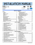
R-410A
J**ZJ SERIES
6-1/2 - 12-1/2 Ton
60 Hertz
TABLE OF CONTENTS
General . . . . . . . . . . . . . . . . . . . . . . . . . . . . . . . . . . . . . . . . . . 2
Installation . . . . . . . . . . . . . . . . . . . . . . . . . . . . . . . . . . . . . . . . 5
Preceding Installation . . . . . . . . . . . . . . . . . . . . . . . . . . . . . 5
Limitations . . . . . . . . . . . . . . . . . . . . . . . . . . . . . . . . . . . . 5
Location. . . . . . . . . . . . . . . . . . . . . . . . . . . . . . . . . . . . . . . . 7
Rigging And Handling . . . . . . . . . . . . . . . . . . . . . . . . . . . . . 7
Ductwork . . . . . . . . . . . . . . . . . . . . . . . . . . . . . . . . . . . . . . 15
Condensate Drain . . . . . . . . . . . . . . . . . . . . . . . . . . . . . . . 16
Compressors. . . . . . . . . . . . . . . . . . . . . . . . . . . . . . . . . . . 16
Filters . . . . . . . . . . . . . . . . . . . . . . . . . . . . . . . . . . . . . . . . 17
Power And Control Wiring. . . . . . . . . . . . . . . . . . . . . . . . . 17
Optional Electric Heat . . . . . . . . . . . . . . . . . . . . . . . . . . . . 30
Optional Gas Heat. . . . . . . . . . . . . . . . . . . . . . . . . . . . . . . 31
Options/Accessories . . . . . . . . . . . . . . . . . . . . . . . . . . . . . 33
Optional Variable Air Volume (VAV) . . . . . . . . . . . . . . . . . 34
Optional Hot Gas Bypass (HGBP) . . . . . . . . . . . . . . . . . . 36
Economizer Interface Overview . . . . . . . . . . . . . . . . . . . . 37
Airflow Performance . . . . . . . . . . . . . . . . . . . . . . . . . . . . . 42
Air Balance . . . . . . . . . . . . . . . . . . . . . . . . . . . . . . . . . . . . 47
Checking Air Quantity . . . . . . . . . . . . . . . . . . . . . . . . . . . .
Operation . . . . . . . . . . . . . . . . . . . . . . . . . . . . . . . . . . . . . . .
Cooling Sequence Of Operation . . . . . . . . . . . . . . . . . . . .
No Outdoor Air Options . . . . . . . . . . . . . . . . . . . . . . . . .
Cooling Operation Errors . . . . . . . . . . . . . . . . . . . . . . . .
Electric Heating Sequence Of Operations . . . . . . . . . . . .
Electric Heat Operation Errors . . . . . . . . . . . . . . . . . . . .
Gas Heating Sequence Of Operations . . . . . . . . . . . . . . .
Ignition Control Board . . . . . . . . . . . . . . . . . . . . . . . . . .
Gas Heating Operation Errors . . . . . . . . . . . . . . . . . . . .
Start-Up (Cooling) . . . . . . . . . . . . . . . . . . . . . . . . . . . . . . . . .
Start-Up (Gas Heat) . . . . . . . . . . . . . . . . . . . . . . . . . . . . . . .
Checking Gas Heat Input . . . . . . . . . . . . . . . . . . . . . . . . . . .
Charging The Unit . . . . . . . . . . . . . . . . . . . . . . . . . . . . . . . . .
Troubleshooting . . . . . . . . . . . . . . . . . . . . . . . . . . . . . . . . . .
Unit Control Board Option Setup . . . . . . . . . . . . . . . . . . . . . .
Option Byte Setup . . . . . . . . . . . . . . . . . . . . . . . . . . . . . . .
Heat Delay Setup . . . . . . . . . . . . . . . . . . . . . . . . . . . . . . .
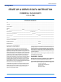
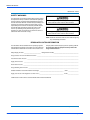
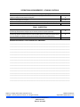
Start-Up Sheet . . . . . . . . . . . . . . . . . . . . . . . . . . . . . . . . . . .
47
50
50
51
53
54
54
55
55
55
57
57
58
60
60
62
62
62
69
LIST OF TABLES
1
2
3
4
5
6
7
8
9
10
11
12
13
14
15
16
J06 thru 12ZJ Unit Limitations . . . . . . . . . . . . . . . . . . . . . . 7
Weights and Dimensions . . . . . . . . . . . . . . . . . . . . . . . . . 8
J06 thru 12ZJ Unit Accessory Weights . . . . . . . . . . . . . . . 9
J06 thru 12ZJ Unit Physical Dimensions . . . . . . . . . . . . 11
J06 thru 12ZJ Unit Clearances . . . . . . . . . . . . . . . . . . . . 11
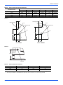
Side Duct Dimensions . . . . . . . . . . . . . . . . . . . . . . . . . . . 14
Control Wire Sizes . . . . . . . . . . . . . . . . . . . . . . . . . . . . . 19
Electrical Data . . . . . . . . . . . . . . . . . . . . . . . . . . . . . . . . . 20
Physical Data . . . . . . . . . . . . . . . . . . . . . . . . . . . . . . . . . 28
Electric Heat Minimum Supply Air . . . . . . . . . . . . . . . . . . 30
Gas Pipe Sizing - Capacity of Pipe . . . . . . . . . . . . . . . . . 31
Gas Heat Minimum Supply Air . . . . . . . . . . . . . . . . . . . . 32
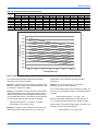
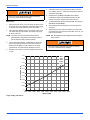
Single Enthalpy and Dual Enthalpy High Limit Curves. . 38
Supply Air Limitations . . . . . . . . . . . . . . . . . . . . . . . . . . . 39
Altitude/Temperature Correction Factors . . . . . . . . . . . . 41
Airflow Performance - Side Duct Application . . . . . . . . . 43
1
2
3
4
5
6
7
8
9
10
11
12
13
14
15
16
17
18
19
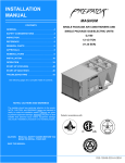
Unit Shipping Bracket . . . . . . . . . . . . . . . . . . . . . . . . . . . 5
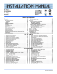
Condenser Covering . . . . . . . . . . . . . . . . . . . . . . . . . . . . 5
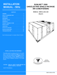
Compressor Section . . . . . . . . . . . . . . . . . . . . . . . . . . . . 5
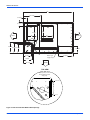
J**ZJ Component Location (J10ZJ Shown) . . . . . . . . . . . 6
Unit 4 Point Load Weight . . . . . . . . . . . . . . . . . . . . . . . . . 8
Unit 6 Point Load Weight . . . . . . . . . . . . . . . . . . . . . . . . . 8
Center of Gravity . . . . . . . . . . . . . . . . . . . . . . . . . . . . . . . 8
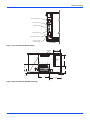
J06 thru 10ZJ Physical Dimensions . . . . . . . . . . . . . . . . . 9
J12ZJ Physical Dimensions . . . . . . . . . . . . . . . . . . . . . . 10
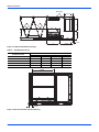
J06 thru 12ZJ Unit Bottom Duct Openings . . . . . . . . . . 12
J06 thru 12ZJ Unit Electrical Entry . . . . . . . . . . . . . . . . . 13
J06 thru 10ZJ Unit Side Duct Openings . . . . . . . . . . . . . 13
J12ZJ Unit Side Duct Openings . . . . . . . . . . . . . . . . . . . 14
J06 thru 12ZJ Unit Left Duct Opening . . . . . . . . . . . . . . 14
J06 thru 12ZJ Roof Curb . . . . . . . . . . . . . . . . . . . . . . . . 15
J06 thru 12ZJ Transition Roof Curb . . . . . . . . . . . . . . . . 15
Side Panels With Hole Plugs . . . . . . . . . . . . . . . . . . . . . 16
Return Downflow Plenum With Panel . . . . . . . . . . . . . . 16
Discharge Panel In Place . . . . . . . . . . . . . . . . . . . . . . . . 16
17
18
19
20
21
22
23
24
25
26
27
28
29
30
31
32
Airflow Performance - Bottom Duct Application . . . . . . .
RPM Selection . . . . . . . . . . . . . . . . . . . . . . . . . . . . . . . .
Indoor Blower Specifications . . . . . . . . . . . . . . . . . . . . . .
Power Exhaust Specifications . . . . . . . . . . . . . . . . . . . .
Motor Sheave Datum Diameters . . . . . . . . . . . . . . . . . .
Additional Static Resistance . . . . . . . . . . . . . . . . . . . . . .
Electric Heat Limit Setting . . . . . . . . . . . . . . . . . . . . . . . .
Electric Heat Anticipator Setpoints . . . . . . . . . . . . . . . . .
Gas Heat Limit Control Settings . . . . . . . . . . . . . . . . . . .
Gas Heat Anticipator Setpoints . . . . . . . . . . . . . . . . . . . .
Gas Rate Cubic Feet Per Hour . . . . . . . . . . . . . . . . . . . .
Gas Heat Stages . . . . . . . . . . . . . . . . . . . . . . . . . . . . . . .
Unit Control Board Flash Codes . . . . . . . . . . . . . . . . . . .
Heat Delay . . . . . . . . . . . . . . . . . . . . . . . . . . . . . . . . . . .
Ignition Control Flash Codes . . . . . . . . . . . . . . . . . . . . . .
VAV Control Board Flash Codes . . . . . . . . . . . . . . . . . .
45
46
47
47
49
50
54
55
56
57
59
59
61
63
63
63
LIST OF FIGURES
20 Condensate Drain . . . . . . . . . . . . . . . . . . . . . . . . . . . . . 16
21 Field Wiring Disconnect - Cooling Unit With/Without Electric
Heat and All Units With VFD Option . . . . . . . . . . . . . . . 18
22 Field Wiring Disconnect - Cooling Unit With Gas Heat
Without VFD Option . . . . . . . . . . . . . . . . . . . . . . . . . . . . 18
23 Typical Electronic Thermostat Field Wiring . . . . . . . . . . 19
24 Typical Field Wiring 24 Volt Thermostat . . . . . . . . . . . . 19
25 Side Entry Gas Piping . . . . . . . . . . . . . . . . . . . . . . . . . . 31
26 Bottom Entry Gas Piping . . . . . . . . . . . . . . . . . . . . . . . . 31
27 Simplified VFD Wiring . . . . . . . . . . . . . . . . . . . . . . . . . . 36
28 Economizer LCD and Keypad Layout. . . . . . . . . . . . . . . 37
29 Single Enthalpy Curve And Boundaries . . . . . . . . . . . . . 38
30 Belt Adjustment . . . . . . . . . . . . . . . . . . . . . . . . . . . . . . . 39
31 Altitude/Temperature Correction Factors . . . . . . . . . . . . 41
32 Dry Coil Delta P . . . . . . . . . . . . . . . . . . . . . . . . . . . . . . . 48
33 Occupied Jumper . . . . . . . . . . . . . . . . . . . . . . . . . . . . . . 51
34 Typical Flame . . . . . . . . . . . . . . . . . . . . . . . . . . . . . . . . . 60
35 Typical Gas Valve . . . . . . . . . . . . . . . . . . . . . . . . . . . . . 60
36 Unit Control Board . . . . . . . . . . . . . . . . . . . . . . . . . . . . . 62
860616-JIM-D-0614
860616-JIM-D-0614
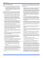
General
Johnson Controls J**ZJ units are single package air
conditioners with optional gas heating designed for outdoor
installation on a rooftop or slab and for non-residential use.
These units can be equipped with factory or field installed
electric heaters for heating applications.
These units are completely assembled on rigid, permanently
attached base rails. All piping, refrigerant charge, and electrical
wiring is factory installed and tested. The units require electric
power, gas supply (where applicable), and duct connections.
The electric heaters have nickel-chrome elements and utilize
single-point power connection.
Before performing service or maintenance operations on
unit, turn off main power switch to unit. Electrical shock
could cause personal injury. Improper installation,
adjustment, alteration, service or maintenance can
cause injury or property damage. Refer to this manual.
For assistance or additional information consult a
qualified installer, service agency or the gas supplier.
Safety Considerations
This is a safety alert symbol. When you see this symbol
on labels or in manuals, be alert to the potential for
personal injury.
Understand and pay particular attention the signal words
DANGER, WARNING or CAUTION.
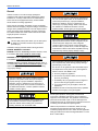
This system uses R-410A Refrigerant which operates at
higher pressures than R-22. No other refrigerant may be
used in this system. Gage sets, hoses, refrigerant
containers and recovery systems must be designed to
handle R-410A. If you are unsure, consult the equipment
manufacturer. Failure to use R-410A compatible servicing
equipment may result in property damage or injury.
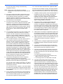
DANGER indicates an imminently hazardous situation, which,
if not avoided, will result in death or serious injury.
WARNING indicates a potentially hazardous situation, which,
if not avoided, could result in death or serious injury.
CAUTION indicates a potentially hazardous situation, which, if
not avoided may result in minor or moderate injury. It is also
used to alert against unsafe practices and hazards involving
only property damage.
If the information in this manual is not followed exactly, a
fire or explosion may result causing property damage,
personal injury or loss of life.
Do not store or use gasoline or other flammable vapors
and liquids in the vicinity of this or any other appliance.
WHAT TO DO IF YOU SMELL GAS:
a. Do not try to light any appliance.
Improper installation may create a condition where the
operation of the product could cause personal injury or
property damage. Improper installation, adjustment,
alteration, service or maintenance can cause injury or
property damage. Refer to this manual for assistance or
for additional information, consult a qualified contractor,
installer or service agency.
This product must be installed in strict compliance with
the installation instructions and any applicable local,
state and national codes including, but not limited to
building, electrical, and mechanical codes.
b. Do not touch any electrical switch; do not use any
phone in your building.
c. Immediately call your gas supplier from a neighbor’s
phone. Follow the gas supplier’s instructions.
d. If you cannot reach your gas supplier, call the fire
department.
Installation and service must be performed by a qualified
installer, service agency or the gas supplier.
Due to system pressure, moving parts, and electrical
components, installation and servicing of air conditioning
equipment can be hazardous. Only qualified, trained service
personnel should install, repair, or service this equipment.
Untrained personnel can perform basic maintenance functions
of cleaning coils and filters and replacing filters.
Observe all precautions in the literature, labels, and tags
accompanying the equipment whenever working on air
conditioning equipment. Be sure to follow all other applicable
safety precautions and codes including ANSI Z223.1 or CSAB149.1- latest edition.
2
Johnson Controls Unitary Products
860616-JIM-D-0614
Wear safety glasses and work gloves. Use quenching cloth and
have a fire extinguisher available during brazing operations.
• Gas Heat Propane Conversion Kit
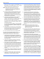
Inspection
• Gas Heat High Altitude Kit (Propane)
• Gas Heat High Altitude Kit (Natural Gas)
• –60F Gas Heat Kit
As soon as a unit is received, it should be inspected for possible
damage during transit. If damage is evident, the extent of the
damage should be noted on the carrier’s freight bill. A separate
request for inspection by the carrier’s agent should be made in
writing.
Renewal Parts
For authorized replacement parts, call Johnson Controls, Inc.
National Source1 Parts Outlet at 1-866-525-9670.
Approvals
Design certified by CSA as follows:
This product must be installed in strict compliance with
the enclosed installation instructions and any applicable
local, state and national codes including, but not limited
to, building, electrical, and mechanical codes.
1.
For use as a cooling only unit, cooling unit with
supplemental electric heat or a forced air furnace.
2.
For outdoor installation only.
3.
For installation on combustible material and may be
installed directly on combustible flooring or, in the U.S., on
wood flooring or Class A, Class B or Class C roof covering
materials.
4.
For use with natural gas (convertible to LP with kit).
The furnace and its individual shut-off valve must be
disconnected from the gas supply piping system during
any pressure testing at pressures in excess of 1/2 PSIG.
Pressures greater than 1/2 PSIG will cause gas valve
damage resulting in a hazardous condition. If it is
subjected to a pressure greater than 1/2 PSIG, the gas
valve must be replaced.
The furnace must be isolated from the gas supply piping
system by closing its individual manual shut-off valve
during any pressure testing of the gas supply piping
system at test pressures equal to or less than 1/2 PSIG
This product must be installed in strict compliance with
the enclosed installation instructions and any applicable
local, state, and national codes including, but not limited
to, building, electrical, and mechanical codes.
Reference
Additional information is available in the following reference
forms:
• Technical Guide - 528199
• General Installation - 860616
• Pre-start & Post-start Check List
Improper installation may create a condition where the
operation of the product could cause personal injury or
property damage.
• Economizer Accessory Downflow Factory Installed
Downflow Field Installed
Horizontal Field Installed
• Motorized Outdoor Air Damper
• Manual Outdoor Air Damper (0-100%)
• Manual Outdoor Air Damper (0-35%)
Johnson Controls Unitary Products
This system uses R-410A Refrigerant which operates at
higher pressures than R-22. No other refrigerant may be
used in this system.
3
860616-JIM-D-0614
Nomenclature
6.5-12.5 Ton Series 10 Model Number Nomenclature
J07 Z J N10 A 2 A AA 6 0 1 2 4 A
Nominal Cooling Capacity
Product Style
J06 = 6.5 Ton
J07 = 7.5 Ton
J08 = 8.5 Ton
J10 = 10.0 Ton
J12 = 12.5 Ton
A = Style A
B = Style B
C = Style C
Configuration Options (not required for all units)
These four digits will not be assigned until a quote is requested, or an order placed.
Product Category
SS Drain Pan
CPC Controller, DFS, APS
Z = A/C, Single Pkg., R-410A
Johnson Controller UNT 1126 (N2 protocol), DFS, APS
Johnson Controller Metasys FEC-2611 (BACnet MS/TP protocol), SAS, RAS, OAS, DFS, APS
Honeywell Controller, DFS, APS
Product Identifier
Novar Controller, DFS, APS
J = 12.2+ EER A/C
Simplicity IntelliComfort II Controller
Simplicity IntelliComfort II Controller w/Simplicity®LINC
Commercial Comfort System (CCS) Rtu Controller
Heat Type and Nominal Heat Capacity
Hot Gas Bypass (Standard on VAV, Optional on CV)
IntelliSpeed with VFD
C00 = Cooling Only. No heat installed
IntelliSpeed, VFD and Manual Bypass
IntelliSpeed, VFD Ready (for customer-provided, field-installed drive)
Variable Air Volume, VFD (not available with factory installed BAS options)
Gas Heat Options
Variable Air Volume, VFD with Simplicity®LINC (not available with factory installed BAS options)
N10 = 100 MBH Output Aluminized Steel
N15 = 150 MBH Output Aluminized Steel
N20 = 200 MBH Output Aluminized Steel
S10 = 100 MBH Output Stainless Steel
S15 = 150 MBH Output Stainless Steel
S20 = 200 MBH Output Stainless Steel
Variable Air Volume, VFD and Manual Bypass
(not available with factory installed BAS options)
Variable Air Volume, VFD and Manual Bypass with Simplicity®LINC
(not available with factory installed BAS options)
Variable Air Volume, VFD (BAS ready)
Variable Air Volume, VFD and Manual Bypass (BAS ready)
Electric Heat Options
Variable Air Volume, VFD Ready (for customer-provided, field-installed drive)
E09 = 9 KW
E18 = 18 KW
E24 = 24 KW
E36 = 36 KW
E54 = 54 KW
Variable Air Volume, VFD Ready with Simplicity®LINC
(for customer-provided, field-installed drive)
2" Pleated Filters, MERV 7
4" Pleated Filters, MERV 13
BAS Ready Economizer (2-10 V.D.C. Actuator without a Controller)
Any Combination of Additional Options that Don’t Have an Option Code Pre-assigned
Airflow
Product Generation
A = Std. Motor
D = Std. Motor/Motorized Damper (Downflow Only)
H = Std Motor/Low Leak Econ/Barometric Relief
(Downflow, Slab Economizer Only)
J = Std Motor/Low Leak Econ/Power Exhaust (Downflow,
Slab Economizer Only)
E = Std Motor/Horizontal Economizer (No Baro)
N = Hi Static
R = Hi Static/Motorized Damper (Downflow Only)
V = Hi Static Mtr/Low Leak Econ/Barometric Relief
(Downflow, Slab Economizer Only)
W = Hi Static Mtr/Low Leak Econ/Power Exhaust
(Downflow, Slab Economizer Only)
S = Hi Static Mtr/Horizontal Economizer (No Baro)
6 = 6th Generation
Additional Options
AA = None
AB = Phase Monitor
AC = Coil Guard
AD = Dirty Filter Switch
AE = Phase Monitor & Coil Guard
AF = Phase Monitor & Dirty Filter Switch
AG = Coil Guard & Dirty Filter Switch
AH = Phase Monitor, Coil Guard & Dirty Filter Switch
RC = Coil Guard, Shipping Bag & American Flag
TA = Technicoat Condenser Coil
TJ = Technicoat Evaporator Coil
TS = Technicoat Evaporator & Condenser Coils
EA = ElectroFin Condenser Coil
EJ = ElectroFin Evaporator Coil
ES = ElectroFin Cond & Evap Coils
ZZ = If desired option combination is not listed above, ZZ will be assigned and configuration options will be
located in digits 15-18.
Installation Options
Voltage
2 = 208/230-3-60
4 = 460-3-60
5 = 575-3-60
A = No Options Installed
B = Option 1
C = Option 2
D = Options 1 & 2
E = Option 3
F = Option 4
G = Options 1 & 3
H = Options 1 & 4
J = Options 1, 2 & 3
K = Options 1, 2, & 4
L = Options 1,3 & 4
M = Options 1, 2, 3, & 4
N = Options 2 & 3
P = Options 2 & 4
Q = Options 2, 3, & 4
R = Options 3 & 4
S = Option 5
T = Options 1 & 5
U = Options 1, 3, & 5
V = Options 1, 4, & 5
W = Options 1, 3, 4, & 5
X = Options 3 & 5
Y = Options 4 & 5
Z = Options 3, 4 & 5
Options
1 = Disconnect
2 = Non-Pwr'd Conv. Outlet
3 = Smoke Detector S.A.
4 = Smoke Detector R.A.
5 = Pwr'd Conv. Outlet
4
Johnson Controls Unitary Products
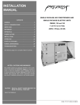
860616-JIM-D-0614
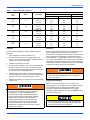
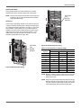
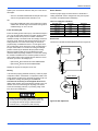
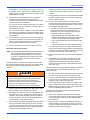
Installation
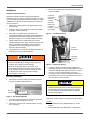
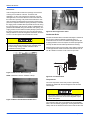
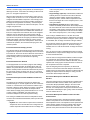
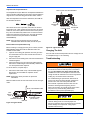
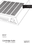
4.
Remove the toolless doorknobs and instruction packet
prior to installation.
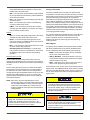
Installation Safety Information
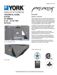
Condenser
Coil External
Protective
Covering
Read these instructions before continuing this appliance
installation. This is an outdoor combination heating and cooling
unit. The installer must assure that these instructions are made
available to the consumer and with instructions to retain them
for future reference.
1.
Refer to the unit rating plate for the approved type of gas
for this product.
2.
Install this unit only in a location and position as specified
on Page 7 of these instructions.
3.
Never test for gas leaks with an open flame. Use
commercially available soap solution made specifically for
the detection of leaks when checking all connections, as
specified on Pages 5, 32, 33 and 58 of these instructions.
4.
Always install furnace to operate within the furnace's
intended temperature-rise range with the duct system and
within the allowable external static pressure range, as
specified on the unit name/rating plate, specified on
Page 60 of these instructions.
5.
Barometric
Relief Hood
in Shipping
Location
(if Included)
Figure 2: Condenser Covering
Toolless
Doorknobs
This equipment is not to be used for temporary heating of
buildings or structures under construction.
Installation
Instruction
Packet
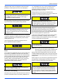
FIRE OR EXPLOSION HAZARD
Failure to follow the safety warning exactly could result
in serious injury, death or property damage.
Never test for gas leaks with an open flame. use a
commercially available soap solution made specifically
for the detection of leaks to check all connections. A fire
or explosion may result causing property damage,
personal injury or loss of life.
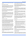
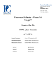
Figure 3: Compressor Section
5.
Preceding Installation
1.
If a factory option convenience outlet is installed, the
weatherproof outlet cover must be field installed. The cover
shall be located behind the filter access panel. To install
the cover, remove the shipping label covering the
convenience outlet, follow the instructions on the back of
the weatherproof cover box, and attach the cover to the
unit using the (4) screws provided.
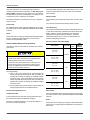
Remove the two screws holding the brackets in the front,
rear and compressor side fork-lift slots.
Bracket
Screws
208/230-3-60 and 380/415-3-50 units with factory
installed Powered Convenience Outlet Option are wired
for 230v and 415v power supply respectively. Change
tap on transformer for 208-3-60 or 380-3-50 operation.
See unit wiring diagram.
Turn down
Figure 1: Unit Shipping Bracket
Limitations
2.
Turn each bracket toward the ground and the protective
plywood covering will drop to the ground.
These units must be installed in accordance with the following:
3.
Remove the condenser coil external protective covering
prior to operation.
1.
National Electrical Code, ANSI/NFPA No. 70 - Latest
Edition
2.
National Fuel Gas Code, ANSI Z223.1 - Latest Edition
Johnson Controls Unitary Products
In U.S.A.:
5
860616-JIM-D-0614
3.
Gas-Fired Central Furnace Standard, ANSI Z21.47 - Latest
Edition
4.
Local building codes, and
5.
Local gas utility requirements
Size of unit for proposed installation should be based on heat
loss/heat gain calculation made according to the methods of Air
Conditioning Contractors of America (ACCA).
This furnace is not to be used for temporary heating of buildings
or structures under construction.
In Canada:
1.
Canadian Electrical Code, CSA C22.1
2.
Installation Codes, CSA - B149.1.
3.
Local plumbing and waste water codes, and
4.
Other applicable local codes.
Refer to unit application data found in this document.
After installation, gas fired units must be adjusted to obtain a
temperature rise within the range specified on the unit rating
plate.
If components are to be added to a unit to meet local codes,
they are to be installed at the dealer’s and/or customer’s
expense.
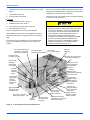
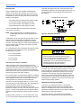
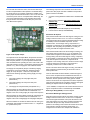
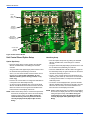
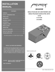
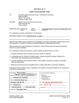
Unit control board w/screw
connector for T-stat wiring
and network connections
The Simplicity® control board used in this product will
effectively operate the cooling system down to 0°F when
this product is applied in a comfort cooling application
for people. An economizer is typically included in this
type of application. When applying this product for
process cooling applications (computer rooms,
switchgear, etc.), please reference applications bulletin
AE-011-07 or call the applications department for
Unitary Products @ 1-877-UPG-SERV for guidance.
Additional accessories may be needed for stable
operation at temperatures below 30° F.
Filter access
Disconnect location
(2” or 4” Filter Options)
(optional disconnect switch)
Terminal block for
hi-voltage connection
Filter drier
(solid core)
Micro-Channel Aluminum Tube
Aluminum Fin Condenser
Second model
nameplate
inside hinged
access panel
Slide-out motor and
blower assembly for
easy adjustment
and service
Dual stage
cooling for
maximum
comfort
Belt-drive
blower motor
VFD Location (Optional)
Power ventor motor
Compressor #2
access (highefficiency
compressor
w/crankcase
heater)
20-gauge aluminized steel tubular
heat exchanger for
long life (stainless
steel option)
Base rails w/forklift
slots (three sides)
and lifting holes
Two-stage gas
heating to maintain
warm, comfortable
temperature
Slide-out drain pan
with 3/4” NPT,
female connection
Roof curbs in eight- and
fourteen-inch heights.
Toolless
door latch
Side entry power
and control wiring
knockouts
Intelligent control
board for safe and
efficient operation
Compressor #1 access
(high-efficiency compressor
w/crankcase heater)
Figure 4: J**ZJ Component Location (J10ZJ Shown)
6
Johnson Controls Unitary Products
860616-JIM-D-0614
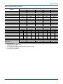
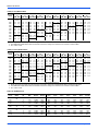
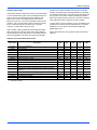
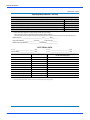
Table 1:
J06 thru 12ZJ Unit Limitations
Unit Limitations
Size
(Tons)
J06
(6.5)
J07
(7.5)
J08
(8.5)
J10
(10)
J12
(12.5)
Model
Unit Voltage
Applied Voltage
Outdoor DB Temp
Min
Max
Max (°F)
208/230-3-60
187
252
125
460-3-60
432
504
125
575-3-60
540
630
125
208/230-3-60
187
252
125
460-3-60
432
504
125
575-3-60
540
630
125
208/230-3-60
187
252
125
460-3-60
432
504
125
575-3-60
540
630
125
208/230-3-60
187
252
125
460-3-60
432
504
125
575-3-60
540
630
125
208/230-3-60
187
252
125
460-3-60
432
504
125
575-3-60
540
630
125
ZJ
ZJ
ZJ
ZJ
ZJ
Location
Clearances
Use the following guidelines to select a suitable location for
these units:
All units require particular clearances for proper operation and
service. Installer must make provisions for adequate
combustion and ventilation air in accordance with section 5.3 of
Air for Combustion and Ventilation of the National Fuel Gas
Code, ANSI Z223.1 – Latest Edition (in U.S.A.), or Sections 7.2,
7.3, or 7.4 of Gas Installation Codes, CSA-B149.1 (in Canada) Latest Edition, and/or applicable provisions of the local building
codes. Refer to Table 5 for clearances required for combustible
construction, servicing, and proper unit operation.
1.
Unit is designed for outdoor installation only.
2.
Condenser coils must have an unlimited supply of air.
Where a choice of location is possible, position the unit on
either north or east side of building.
3.
Suitable for mounting on roof curb.
4.
For ground level installation, use a level concrete slab with
a minimum thickness of 4 inches. The length and width
should be at least 6 inches greater than the unit base rails.
Do not tie slab to the building foundation.
5.
Roof structures must be able to support the weight of the
unit and its options/accessories. Unit must be installed on a
solid, level roof curb or appropriate angle iron frame.
6.
Maintain level tolerance to 1/2” across the entire width and
length of unit.
Excessive exposure of this furnace to contaminated
combustion air may result in equipment damage or
personal injury. Typical contaminates include:
permanent wave solution, chlorinated waxes and
cleaners, chlorine based swimming pool chemicals,
water softening chemicals, carbon tetrachloride,
Halogen type refrigerants, cleaning solvents (e.g.
perchloroethylene), printing inks, paint removers,
varnishes, hydrochloric acid, cements and glues,
antistatic fabric softeners for clothes dryers, masonry
acid washing materials.
Johnson Controls Unitary Products
Do not permit overhanging structures or shrubs to
obstruct condenser air discharge outlet, combustion air
inlet or vent outlets.
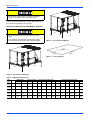
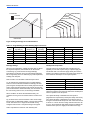
Rigging And Handling
Exercise care when moving the unit. Do not remove any
packaging until the unit is near the place of installation. Rig the
unit by attaching chain or cable slings to the lifting holes
provided in the base rails. Spreader bars, whose length
exceeds the largest dimension across the unit, MUST be used
across the top of the unit.
If a unit is to be installed on a roof curb other than a UP
roof curb, gasketing must be applied to all surfaces that
come in contact with the unit underside.
7
860616-JIM-D-0614
Before lifting, make sure the unit weight is distributed
equally on the rigging cables so it will lift evenly.
Units may be moved or lifted with a forklift. Slotted openings in
the base rails are provided for this purpose.
LENGTH OF FORKS MUST BE A MINIMUM OF 60 INCHES.
FRONT
LEFT
All panels must be secured in place when the unit is
lifted.
D
C
B
A
E
F
The condenser coils should be protected from rigging
cable damage with plywood or other suitable material.
Figure 6: Unit 6 Point Load Weight
Y
X
FRONT
LEFT
Figure 7: Center of Gravity
FRONT
LEFT
B
C
A
D
Figure 5: Unit 4 Point Load Weight
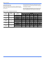
Table 2:
Weights and Dimensions
Weight (lbs.)
Center of Gravity
Size
Model
(Tons)
Shipping Operating
X
Y
J06
ZJ
1035
1030
39
25
(6.5)
J07
ZJ
1055
1050
39
25
(7.5)
J08
ZJ
1065
1060
38
24
(8.5)
J10
ZJ
1075
1070
39
24
(10)
J12
ZJ
1285
1280
48
24
(12.5)
8
4 Point Load Location (lbs.)
A
B
C
D
A
6 Point Load Location (lbs.)
B
C
D
E
F
245
191
260
333
170
144
122
167
195
232
250
195
265
340
174
146
125
170
199
236
247
184
268
360
173
141
117
171
206
253
245
191
278
357
170
143
122
178
209
248
240
281
410
350
156
173
192
280
252
227
Johnson Controls Unitary Products
860616-JIM-D-0614
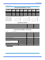
Table 3:
J06 thru 12ZJ Unit Accessory Weights
Unit Accessory
Economizer
Power Exhaust
Electric Heat1
Gas Heat2
Variable Frequency Drive3
Weight (lbs.)
Shipping
Operating
90
85
40
35
49
49
110
110
30
30
1. Weight given is for the maximum heater size available
(54KW).
2. Weight given is for the maximum number of tube heat
exchangers available (8 tube).
3. Weight includes mounting hardware, controls and manual
bypass option.
29.69
15.25
15.38
59.00
15.38
2X Ø 24.38
B
SEE DETAIL A FOR GAS INLET
A
C
D
E
11.38
F
59.00
4.19
LEFT
27.31
SEE DETAIL B
FOR DRAIN LOCATION
21.19
89.00
FRONT
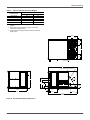
Figure 8: J06 thru 10ZJ Physical Dimensions
Johnson Controls Unitary Products
9
860616-JIM-D-0614
28.86
29.66
44.09
15.23
14.85
29.03
29.03
14.85
Ø 24.58 TYP. 4 PL.
15.23
B
See detail A for gas inlet
A
C
D
E
11 3/8
F
See detail B for drain location
LEFT
59
4 3/16
21 3/16
FRONT
27 5/16
89
Figure 9: J12ZJ Physical Dimensions
10
Johnson Controls Unitary Products
860616-JIM-D-0614
Table 4:
J06 thru 12ZJ Unit Physical Dimensions
Unit Model Number
A
50 3/4
50 3/4
50 3/4
50 3/4
50 3/4
J06ZJ
J07ZJ
J08ZJ
J10ZJ
J12ZJ
B
89
89
89
89
119 1/2
Dimension (in.)
C
D
30 3/16
24 3/16
30 3/16
24 3/16
30 3/16
24 3/16
30 3/16
24 3/16
30 3/16
24 3/16
E
17 3/16
17 3/16
17 3/16
17 3/16
17 3/16
F
6 3/16
6 3/16
6 3/16
6 3/16
6 3/16
Detail A
3.184
3.184
Gas Pipe Inlet
Gas Pipe Inlet
Ø 2.000
Ø 2.000
Gas Exhaust Vent
Gas Exhaust Vent
Ø 3.126
Ø 3.126
17.541
14.594
7.715
7.705
4.737
4.727
42” CABINET
50 3/4” CABINET
Detail B
5-3/8
3/4” FPT
Table 5:
J06 thru 12ZJ Unit Clearances
Direction
Top1
Front
Rear
Distance (in.)
72
36
36
Direction
Right
Left
Bottom2
Distance (in.)
12
36
0
1. Units must be installed outdoors. Over hanging structure or shrubs should not obscure condenser air discharge outlet.
2. Units may be installed on combustable floors made from wood or class A, B or C roof covering materials.
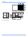
Johnson Controls Unitary Products
11
860616-JIM-D-0614
89
32 11/16
6 13/16
6 13/16
SUPPLY
AIR
RETURN
AIR
24
27 1/2
LEFT
21
18
RIGHT
20 1/8 19 1/8
17 1/8
12 5/16
Bottom condensate drain
14 1/2
25 9/16
Bottom gas
supply entry
16 3/8
18 1/16
FRONT
TOP VIEW
Bottom power, control
and convenience outlet
wiring entry
3X Ø 0.875
Ø 2.469
Figure 10: J06 thru 12ZJ Unit Bottom Duct Openings
12
Johnson Controls Unitary Products
860616-JIM-D-0614
Disconnect Swith Cover
Power Entry Ø 2-1/2
Control Entry Ø 7/8
Power Entry Ø 2-1/2
Convenience Outlet Cover
Convenience Outlet
Power Entry Ø 7/8
FRONT
Figure 11: J06 thru 12ZJ Unit Electrical Entry
Dot Plugs
18-1/4
Return
Air
A
Supply Air
D
B
2-31/32
5-5/32
C
31-11/16
Figure 12: J06 thru 10ZJ Unit Side Duct Openings
Johnson Controls Unitary Products
13
860616-JIM-D-0614
Dot Plugs
18-1/4
A
D
B
5-5/32
2-7/8
C
31-5/8
Figure 13: J12ZJ Unit Side Duct Openings
Table 6:
Side Duct Dimensions
Unit Model Number
Dimension (in.)
A
B
C
D
J06ZJ
28 1/4
18 1/16
28 1/4
18 1/4
J07ZJ
28 1/4
18 1/16
28 1/4
18 1/4
J08ZJ
28 1/4
18 1/16
28 1/4
18 1/4
J10ZJ
28 1/4
18 1/16
28 1/4
18 1/4
J12ZJ
28 1/4
18 1/16
28 1/4
18 1/4
30-3/8
4-5/16
Figure 14: J06 thru 12ZJ Unit Left Duct Opening
14
Johnson Controls Unitary Products
860616-JIM-D-0614
RIGHT
80-5/8
INSULATED DECK UNDER
CONDENSER SECTION
20
SUPPLY
20
6
RETURN
2 TYP.
30
INSULATED DECK UNDER
COMPRESSOR SECTION
50-1/2
FRONT
8 or 14
Figure 15: J06 thru 12ZJ Roof Curb
2 TYP
50-1/2
30-1/2
23 4
80-5/8
26
RETURN
SUPPLY
10
76-5/8
94
FRONT
59-1/4
64-1/4
RIGHT
Figure 16: J06 thru 12ZJ Transition Roof Curb
Ductwork
Ductwork should be designed and sized according to the
methods in Manual D of the Air Conditioning Contractors of
America (ACCA) or as recommended by any other recognized
authority such as ASHRAE or SMACNA.
A closed return duct system should be used. This will not
preclude use of economizers or outdoor fresh air intake. The
Johnson Controls Unitary Products
supply and return air duct connections at the unit should be
made with flexible joints to minimize noise.
The supply and return air duct systems should be designed for
the CFM and static pressure requirements of the job. They
should NOT be sized to match the dimensions of the duct
connections on the unit.
Refer to Figure 10 for bottom air duct openings. Refer to
Figures 12, 13 and Table 6 for side air duct openings.
15
860616-JIM-D-0614
Duct Covers
Units are shipped with the side duct openings covered and a
covering over the bottom of the unit. For bottom duct
application, no duct cover changes are necessary. For side
duct application, remove the side duct covers and install over
the bottom duct openings. The panels removed from the side
duct connections are designed to be reused by securing each
panel to its respective downflow opening. But keep in mind that
the supply panel is installed with the painted surface UP, facing
the heat exchanger, while the return panel is installed with the
painted surface DOWN, facing the downflow duct opening. The
supply panel is secured with the bracket (already in place from
the factory) and two screws. It’s a snug fit for the panel when
sliding it between the heat exchanger and unit bottom, but there
is room. The return panel is secured with four screws.
When fastening ductwork to side duct flanges on unit,
insert screws through duct flanges only. DO NOT insert
screws through casing. Outdoor ductwork must be
insulated and water-proofed.
Figure 19: Discharge Panel In Place
Condensate Drain
The side condensate drain is reversible and maybe re-oriented to
the rear of the cabinet to facilitate condensate piping. A
condensate drain connection is available through the base pan
for piping inside the roof curb. Trap the connection per Figure 20.
The trap and drain lines should be protected from freezing.
Plumbing must conform to local codes. Use a sealing compound
on male pipe threads. Install condensate drain line from the 3/4
inch NPT female connection on the unit to an open drain.
3" Minimum
Figure 17: Side Panels With Hole Plugs
NOTE: Orientation. Panel is “insulation” side up.
Figure 20: Condensate Drain
Compressors
The scroll compressor used in this product is specifically
designed to operate with R-410A Refrigerant and cannot be
interchanged.
Figure 18: Return Downflow Plenum With Panel
This system uses R-410A Refrigerant which operates at
higher pressures than R-22. No other refrigerant may be
used in this system.
The compressor also uses a polyolester (POE oil), Mobil 3MA
POE. This oil is extremely hygroscopic, meaning it absorbs water
readily. POE oil can absorb 15 times as much water as other oils
16
Johnson Controls Unitary Products
860616-JIM-D-0614
designed for HCFC and CFC refrigerants. Take all necessary
precautions to avoid exposure of the oil to the atmosphere.
Do not leave the system open to the atmosphere. Unit
damage could occur due to moisture being absorbed by
the POE oil in the system. This type of oil is highly
susceptible to moisture absorption
POE (polyolester) compressor lubricants are known to cause
long term damage to some synthetic roofing materials.
70 – Latest Edition (in U.S.A.), current Canadian Electrical
Code C221, and/or local ordinances. The unit must be
electrically grounded in accordance with NEC and CEC as
specified above and/or local codes.
Voltage tolerances which must be maintained at the
compressor terminals during starting and running conditions are
indicated on the unit Rating Plate and Table 1.
208/230-3-60 and 380/415-3-50 units control
transformers are factory wired for 230v and 415v power
supply respectively. Change tap on transformer for 2083-60 or 380-3-50 operation. See unit wiring diagram.
Exposure, even if immediately cleaned up, may cause
embrittlement (leading to cracking) to occur in one year
or more. When performing any service that may risk
exposure of compressor oil to the roof, take precautions
to protect roofing.
The internal wiring harnesses furnished with this unit are an
integral part of the design certified unit. Field alteration to
comply with electrical codes should not be required. If any of
the wire supplied with the unit must be replaced, replacement
wire must be of the type shown on the wiring diagram and the
same minimum gauge as the replaced wire.
Procedures which risk oil leakage include, but are not limited to,
compressor replacement, repairing refrigerant leaks, replacing
refrigerant components such as filter drier, pressure switch,
metering device or coil.
A disconnect must be utilized for these units. Factory installed
disconnects are available. If installing a disconnect (field
supplied or Unitary Product supplied accessory), refer to Figure
4 for the recommended mounting location.
Units are shipped with compressor mountings which are
factory-adjusted and ready for operation.
Avoid damage to internal components if drilling holes for
disconnect mounting.
Do not loosen compressor mounting bolts.
Filters
Two-inch filters are supplied with each unit. One-inch filters may
be used with no modification to the filter racks. Filters must
always be installed ahead of evaporator coil and must be kept
clean or replaced with same size and type. Dirty filters reduce
the capacity of the unit and result in frosted coils or safety
shutdown. Refer to physical data tables, for the number and
size of filters needed for the unit. The unit should not be
operated without filters properly installed.
Make sure that panel latches are properly positioned on
the unit to maintain an airtight seal.
Power And Control Wiring
Field wiring to the unit, fuses, and disconnects must conform to
provisions of National Electrical Code (NEC), ANSI/NFPA No.
Johnson Controls Unitary Products
NOTE: Since not all local codes allow the mounting of a
disconnect on the unit, please confirm compliance with
local code before mounting a disconnect on the unit.
Electrical line must be sized properly to carry the load. USE
COPPER CONDUCTORS ONLY. Each unit must be wired with
a separate branch circuit fed directly from the meter panel and
properly fused.
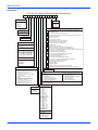
Refer to Figures 21, 22, 23 and 24 for typical field wiring and to
the appropriate unit wiring diagram mounted inside control
doors for control circuit and power wiring information.
When connecting electrical power and control wiring to
the unit, water-proof connectors must be used so that
water or moisture cannot be drawn into the unit during
normal operation. The above water-proofing conditions
will also apply when installing a field supplied disconnect
switch.
17
860616-JIM-D-0614
Power Wiring Detail
Units are factory wired for the voltage shown on the unit
nameplate. Refer to Electrical Data Table 8 to size power
wiring, fuses, and disconnect switch.
Power wiring is brought into the unit through the side of the unit
or the basepan inside the curb.
TERMINAL BLOCK TB1
FACTORY OR FIELD
SUPPLIED DISCONNECT
GROUND
LUG
THREE
PHASE
POWER
SUPPLY
Figure 21: Field Wiring Disconnect - Cooling Unit With/Without Electric Heat and All Units With VFD Option
CONTACTOR 1M
GROUND
LUG
T1
T2
T3
L1
L2
L3
FACTORY OR FIELD
SUPPLIED DISCONNECT
THREE
PHASE
POWER
SUPPLY
Figure 22: Field Wiring Disconnect - Cooling Unit With Gas Heat Without VFD Option
18
Johnson Controls Unitary Products
860616-JIM-D-0614
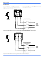
Thermostat Wiring (Not applicable to units with VFD)
thermostat to the unit. Refer to Table 7 for control wire sizing
and maximum length.
The thermostat should be located on an inside wall
approximately 56 inch above the floor where it will not be
subject to drafts, sun exposure or heat from electrical fixtures or
appliances. Follow the manufacturer's instructions enclosed
with thermostat for general installation procedure. Seven (7)
color-coded, insulated wires should be used to connect the
THERMOSTAT1
TERMINALS
RC
UNIT TERMINALS
STRIP TB1
RH
R
Y1
Y1
Y2
Y2
W1
W1
W2
W2
G
G
C
C
X1
X3
Table 7:
Control Wire Sizes
Wire Size
Maximum Length1
18 AWG
150 Feet
1. From the unit to the thermostat and back to the unit.
208/230-3-60 and 380/415-3-50 units control
transformers are factory wired for 230v and 415v power
supply respectively. Change tap on transformer for 2083-60 or 380-3-50 operation. See unit wiring diagram.
24 Volt
Transformer
X
OCC
2
X4
A1
A2
T
T
TO REMOTE SENSOR
2ET04701324 IF USED
1
2
Electronic programmable Thermostat 2ET0770010124 (includes subbase).
Terminals A1 and A2 provide a relay output to close the outdoor economizer
dampers when the thermostat switches to the set-back position.
Figure 23: Typical Electronic Thermostat Field Wiring
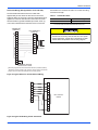
T-STAT
W1
W1
W2
W2
Y1
Y1
G
G
Y2
OCC
RH
RC
REMOTE
MIN POS
C
UNIT CONTROL
BOARD
Y2
X
R
SD
C
Figure 24: Typical Field Wiring 24 Volt Thermostat
Johnson Controls Unitary Products
19
860616-JIM-D-0614
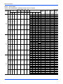
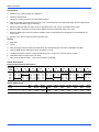
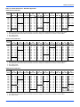
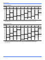
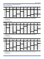
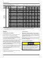
Table 8: Electrical Data
J06 thru 12ZJ Standard Motor - Without Powered Convenience Outlet
Size
(Tons)
Volt
Compressors
(each)
RLA LRA
MCC
OD Fan
Motors
(each)
Supply
Blower
Motor
Pwr
Exh
Motor
Pwr
Conv
Outlet
FLA
FLA
FLA
FLA
208
9.3
68
14.5
1.5
6.0
5.5
0.0
230
9.3
68
14.5
1.5
6.0
5.5
0.0
460
4.9
34
7.6
0.8
3.0
2.2
0.0
575
3.8
28
6
0.6
2.4
1.8
0.0
208
11.9
88
18.5
3.5
6.0
5.5
0.0
230
11.9
88
18.5
3.5
6.0
5.5
0.0
460
5.2
44
8.1
1.6
3.0
2.2
0.0
575
4.8
36
7.5
1.3
2.4
1.8
0.0
208
12.2
88
19
3.5
6.8
5.5
0.0
230
12.2
88
19
3.5
6.8
5.5
0.0
460
5.8
44
9
1.6
3.4
2.2
0.0
575
4.4
36
5.5
1.3
2.7
1.8
0.0
J06
(6.5)
J07
(7.5)
J08
(8.5)
20
Electric Heat Option
Model
kW
None
E09
E18
E24
E36
None
E09
E18
E24
E36
None
E09
E18
E24
E36
None
E09
E18
E24
E36
None
E09
E18
E24
E36
None
E09
E18
E24
E36
None
E09
E18
E24
E36
None
E09
E18
E24
E36
None
E09
E18
E24
E36
None
E09
E18
E24
E36
None
E09
E18
E24
E36
None
E09
E18
E24
E36
6.8
13.5
18
25.5
9
18
24
34
9
18
24
34
9
18
24
34
6.8
13.5
18
25.5
9
18
24
34
9
18
24
34
9
18
24
34
6.8
13.5
18
25.5
9
18
24
34
9
18
24
34
9
18
24
34
MCA
(Amps)
MCA1
w/Pwr
Exh
(Amps)
29.9
31.1
54.3
70
96
29.9
34.6
61.6
79.7
109.7
15.6
17.3
30.8
39.8
54.9
12.2
13.8
24.7
31.9
43.9
39.8
39.8
54.3
70
96
39.8
39.8
61.6
79.7
109.7
17.9
17.9
30.8
39.8
54.9
15.8
15.8
24.7
31.9
43.9
41.3
41.3
55.3
71
97
41.3
41.3
62.6
80.7
110.7
19.7
19.7
31.3
40.3
55.4
15.2
15.2
25
32.2
44.3
35.4
38
61.2
76.8
102.9
35.4
41.4
68.5
86.5
116.6
17.8
20
33.6
42.6
57.6
14
16.1
26.9
34.1
46.1
45.3
45.3
61.2
76.8
102.9
45.3
45.3
68.5
86.5
116.6
20.1
20.1
33.6
42.6
57.6
17.6
17.6
26.9
34.1
46.1
46.8
46.8
62.2
77.8
103.9
46.8
46.8
69.5
87.5
117.6
21.9
21.9
34.1
43.1
58.1
17
17
27.3
34.5
46.5
1
Stages Amps
1
2
2
2
1
2
2
2
1
2
2
2
1
2
2
2
1
2
2
2
1
2
2
2
1
2
2
2
1
2
2
2
1
2
2
2
1
2
2
2
1
2
2
2
1
2
2
2
18.9
37.5
50.0
70.8
21.7
43.3
57.7
81.8
10.8
21.7
28.9
40.9
8.7
17.3
23.1
32.7
18.9
37.5
50.0
70.8
21.7
43.3
57.7
81.8
10.8
21.7
28.9
40.9
8.7
17.3
23.1
32.7
18.9
37.5
50.0
70.8
21.7
43.3
57.7
81.8
10.8
21.7
28.9
40.9
8.7
17.3
23.1
32.7
2
Max Fuse2/ Max Fuse3 /
Breaker
3
Breaker
Size w/ Pwr
Size
Exh
(Amps)
(Amps)
35
40
35
40
60
70
70
80
100
110
35
40
35
45
70
70
80
90
110
125
20
20
20
20
35
35
40
45
60
60
15
15
15
20
25
30
35
35
45
50
50
50
50
50
60
70
70
80
100
110
50
50
50
50
70
70
80
90
110
125
20
25
20
25
35
35
40
45
60
60
20
20
20
20
25
30
35
35
45
50
50
50
50
50
60
70
80
80
100
110
50
50
50
50
70
70
90
90
125
125
25
25
25
25
35
35
45
45
60
60
20
20
20
20
25
30
35
35
45
50
Johnson Controls Unitary Products
860616-JIM-D-0614
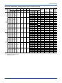
J06 thru 12ZJ Standard Motor - Without Powered Convenience Outlet (Continued)
Size
(Tons)
Volt
Compressors
(each)
RLA LRA
MCC
OD Fan
Motors
(each)
Supply
Blower
Motor
Pwr
Exh
Motor
Pwr
Conv
Outlet
FLA
FLA
FLA
FLA
208
16
110
24.9
3.5
6.8
5.5
0.0
230
16
110
24.9
3.5
6.8
5.5
0.0
460
7.8
52
12.1
1.6
3.4
2.2
0.0
575
5.7
38.9
8.9
1.3
2.7
1.8
0.0
208
23.1
160
36
1.5
9.6
5.5
0.0
230
23.1
160
36
1.5
9.6
5.5
0.0
460
12.2
87
19
0.8
4.8
2.2
0.0
575
8.7
62
13.5
0.6
3.9
1.8
0.0
J10
(10)
J12
(12.5)
Electric Heat Option
Model
kW
None
E18
E24
E36
E54
None
E18
E24
E36
E54
None
E18
E24
E36
E54
None
E18
E24
E36
E54
None
E18
E24
E36
E54
None
E18
E24
E36
E54
None
E18
E24
E36
E54
None
E18
E24
E36
E54
13.5
18
25.5
40.6
18
24
34
54
18
24
34
54
18
24
34
54
13.5
18
25.5
40.6
18
24
34
54
18
24
34
54
18
24
34
54
MCA
(Amps)
MCA1
w/Pwr
Exh
(Amps)
49.8
55.3
71
97
149.4
49.8
62.6
80.7
110.7
138.4
24.2
31.3
40.3
55.4
69.2
18.1
25
32.2
44.3
55.3
67.6
67.6
74.5
100.5
152.9
67.6
67.6
84.2
114.2
141.9
35.5
35.5
42.1
57.1
71
25.9
26.5
33.7
45.8
56.8
55.3
62.2
77.8
103.9
156.2
55.3
69.5
87.5
117.6
145.3
26.4
34.1
43.1
58.1
72
19.9
27.3
34.5
46.5
57.6
73.1
73.1
81.3
107.4
159.7
73.1
73.1
91
121.1
148.8
37.7
37.7
44.8
59.9
73.7
27.7
28.8
36
48
59.1
1
Stages Amps
2
2
2
2
2
2
2
2
2
2
2
2
2
2
2
2
2
2
2
2
2
2
2
2
2
2
2
2
2
2
2
2
37.5
50.0
70.8
112.7
43.3
57.7
81.8
129.9
21.7
28.9
40.9
65.0
17.3
23.1
32.7
52.0
37.5
50.0
70.8
112.7
43.3
57.7
81.8
129.9
21.7
28.9
40.9
65.0
17.3
23.1
32.7
52.0
2
Max Fuse2/ Max Fuse3 /
Breaker
3
Breaker
Size w/ Pwr
Size
Exh
(Amps)
(Amps)
60
70
60
70
80
80
100
110
150
175
60
70
70
70
90
90
125
125
150
175
30
30
35
35
45
45
60
60
80
80
20
25
25
30
35
35
45
50
60
60
90
90
90
90
90
90
110
110
175
175
90
90
90
90
90
100
125
125
175
175
45
45
45
45
45
45
60
60
80
80
30
35
30
35
35
40
50
50
70
70
1. Minimum Circuit Ampacity.
2. Dual Element, Time Delay Type.
3. HACR type per NEC.
Johnson Controls Unitary Products
21
860616-JIM-D-0614
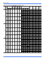
J06 thru 12ZJ Hi Static Motor - Without Powered Convenience Outlet
Size
(Tons)
Volt
Compressors
(each)
RLA LRA
MCC
OD Fan
Motors
(each)
Supply
Blower
Motor
Pwr
Exh
Motor
Pwr
Conv
Outlet
FLA
FLA
FLA
FLA
208
9.3
68
14.5
1.5
6.8
5.5
0.0
230
9.3
68
14.5
1.5
6.8
5.5
0.0
460
4.9
34
7.6
0.8
3.4
2.2
0.0
575
3.8
28
6
0.6
2.7
1.8
0.0
208
11.9
88
18.5
3.5
9.6
5.5
0.0
230
11.9
88
18.5
3.5
9.6
5.5
0.0
460
5.2
44
8.1
1.6
4.8
2.2
0.0
575
4.8
36
7.5
1.3
3.9
1.8
0.0
208
12.2
88
19
3.5
9.6
5.5
0.0
230
12.2
88
19
3.5
9.6
5.5
0.0
460
5.8
44
9
1.6
4.8
2.2
0.0
575
4.4
36
5.5
1.3
3.9
1.8
0.0
J06
(6.5)
J07
(7.5)
J08
(8.5)
22
Electric Heat Option
Model
kW
None
E09
E18
E24
E36
None
E09
E18
E24
E36
None
E09
E18
E24
E36
None
E09
E18
E24
E36
None
E09
E18
E24
E36
None
E09
E18
E24
E36
None
E09
E18
E24
E36
None
E09
E18
E24
E36
None
E09
E18
E24
E36
None
E09
E18
E24
E36
None
E09
E18
E24
E36
None
E09
E18
E24
E36
6.8
13.5
18
25.5
9
18
24
34
9
18
24
34
9
18
24
34
6.8
13.5
18
25.5
9
18
24
34
9
18
24
34
9
18
24
34
6.8
13.5
18
25.5
9
18
24
34
9
18
24
34
9
18
24
34
MCA1
(Amps)
MCA1
w/Pwr
Exh
(Amps)
30.7
32.1
55.3
71
97
30.7
35.6
62.6
80.7
110.7
16
17.8
31.3
40.3
55.4
12.5
14.2
25
32.2
44.3
43.4
43.4
58.8
74.5
100.5
43.4
43.4
66.1
84.2
114.2
19.7
19.7
33.1
42.1
57.1
17.3
17.3
26.5
33.7
45.8
44.1
44.1
58.8
74.5
100.5
44.1
44.1
66.1
84.2
114.2
21.1
21.1
33.1
42.1
57.1
16.4
16.4
26.5
33.7
45.8
36.2
39
62.2
77.8
103.9
36.2
42.4
69.5
87.5
117.6
18.2
20.5
34.1
43.1
58.1
14.3
16.5
27.3
34.5
46.5
48.9
48.9
65.7
81.3
107.4
48.9
48.9
73
91
121.1
21.9
22.3
35.8
44.8
59.9
19.1
19.1
28.8
36
48
49.6
49.6
65.7
81.3
107.4
49.6
49.6
73
91
121.1
23.3
23.3
35.8
44.8
59.9
18.2
18.2
28.8
36
48
Stages Amps
1
2
2
2
1
2
2
2
1
2
2
2
1
2
2
2
1
2
2
2
1
2
2
2
1
2
2
2
1
2
2
2
1
2
2
2
1
2
2
2
1
2
2
2
1
2
2
2
18.9
37.5
50.0
70.8
21.7
43.3
57.7
81.8
10.8
21.7
28.9
40.9
8.7
17.3
23.1
32.7
18.9
37.5
50.0
70.8
21.7
43.3
57.7
81.8
10.8
21.7
28.9
40.9
8.7
17.3
23.1
32.7
18.9
37.5
50.0
70.8
21.7
43.3
57.7
81.8
10.8
21.7
28.9
40.9
8.7
17.3
23.1
32.7
2
Max Fuse2/ Max Fuse3 /
Breaker
Breaker3
Size w/ Pwr
Size
Exh
(Amps)
(Amps)
40
45
40
45
60
70
80
80
100
110
40
45
40
45
70
70
90
90
125
125
20
20
20
25
35
35
45
45
60
60
15
15
15
20
25
30
35
35
45
50
50
60
50
60
60
70
80
90
110
110
50
60
50
60
70
80
90
100
125
125
20
25
20
25
35
40
45
45
60
60
20
20
20
20
30
30
35
40
50
50
50
60
50
60
60
70
80
90
110
110
50
60
50
60
70
80
90
100
125
125
25
25
25
25
35
40
45
45
60
60
20
20
20
20
30
30
35
40
50
50
Johnson Controls Unitary Products
860616-JIM-D-0614
J06 thru 12ZJ Hi Static Motor - Without Powered Convenience Outlet (Continued)
Size
(Tons)
Volt
Compressors
(each)
RLA LRA
MCC
OD Fan
Motors
(each)
Supply
Blower
Motor
Pwr
Exh
Motor
Pwr
Conv
Outlet
FLA
FLA
FLA
FLA
208
16
110
24.9
3.5
9.6
5.5
0.0
230
16
110
24.9
3.5
9.6
5.5
0.0
460
7.8
52
12.1
1.6
4.8
2.2
0.0
575
5.7
38.9
8.9
1.3
3.9
1.8
0.0
208
23.1
160
36
1.5
15.2
5.5
0.0
230
23.1
160
36
1.5
15.2
5.5
0.0
460
12.2
87
19
0.8
7.6
2.2
0.0
575
8.7
62
13.5
0.6
6.1
1.8
0.0
J10
(10)
J12
(12.5)
Electric Heat Option
Model
kW
None
E18
E24
E36
E54
None
E18
E24
E36
E54
None
E18
E24
E36
E54
None
E18
E24
E36
E54
None
E18
E24
E36
E54
None
E18
E24
E36
E54
None
E18
E24
E36
E54
None
E18
E24
E36
E54
13.5
18
25.5
40.6
18
24
34
54
18
24
34
54
18
24
34
54
13.5
18
25.5
40.6
18
24
34
54
18
24
34
54
18
24
34
54
MCA
(Amps)
MCA1
w/Pwr
Exh
(Amps)
52.6
58.8
74.5
100.5
152.9
52.6
66.1
84.2
114.2
141.9
25.6
33.1
42.1
57.1
71
19.3
26.5
33.7
45.8
56.8
73.2
73.2
81.5
107.5
159.9
73.2
73.2
91.2
121.2
148.9
38.3
38.3
45.6
60.6
74.5
28.1
29.3
36.5
48.5
59.6
58.1
65.7
81.3
107.4
159.7
58.1
73
91
121.1
148.8
27.8
35.8
44.8
59.9
73.7
21.1
28.8
36
48
59.1
78.7
78.7
88.3
114.4
166.7
78.7
80
98
128.1
155.8
40.5
40.5
48.3
63.4
77.2
29.9
31.5
38.7
50.8
61.8
1
Stages Amps
2
2
2
2
2
2
2
2
2
2
2
2
2
2
2
2
2
2
2
2
2
2
2
2
2
2
2
2
2
2
2
2
37.5
50.0
70.8
112.7
43.3
57.7
81.8
129.9
21.7
28.9
40.9
65.0
17.3
23.1
32.7
52.0
37.5
50.0
70.8
112.7
43.3
57.7
81.8
129.9
21.7
28.9
40.9
65.0
17.3
23.1
32.7
52.0
2
Max Fuse2/ Max Fuse3 /
Breaker
3
Breaker
Size w/ Pwr
Size
Exh
(Amps)
(Amps)
60
70
60
70
80
90
110
110
175
175
60
70
70
80
90
100
125
125
175
175
30
35
35
40
45
45
60
60
80
80
25
25
30
30
35
40
50
50
70
70
90
100
90
100
90
100
110
125
175
175
90
100
90
100
100
100
125
150
175
175
50
50
50
50
50
50
70
70
90
90
35
35
35
35
40
40
50
60
70
70
1. Minimum Circuit Ampacity.
2. Dual Element, Time Delay Type.
3. HACR type per NEC.
Johnson Controls Unitary Products
23
860616-JIM-D-0614
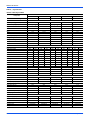
J06 thru 12ZJ Standard Motor - With Powered Convenience Outlet
Size
(Tons)
Volt
Compressors
(each)
RLA LRA
MCC
OD Fan
Motors
(each)
Supply
Blower
Motor
Pwr
Exh
Motor
Pwr
Conv
Outlet
FLA
FLA
FLA
FLA
208
9.3
68
14.5
1.5
6.0
5.5
10.0
230
9.3
68
14.5
1.5
6.0
5.5
10.0
460
4.9
34
7.6
0.8
3.0
2.2
5.0
575
3.8
28
6
0.6
2.4
1.8
4.0
208
11.9
88
18.5
3.5
6.0
5.5
10.0
230
11.9
88
18.5
3.5
6.0
5.5
10.0
460
5.2
44
8.1
1.6
3.0
2.2
5.0
575
4.8
36
7.5
1.3
2.4
1.8
4.0
208
12.2
88
19
3.5
6.8
5.5
10.0
230
12.2
88
19
3.5
6.8
5.5
10.0
460
5.8
44
9
1.6
3.4
2.2
5.0
575
4.4
36
5.5
1.3
2.7
1.8
4.0
J06
(6.5)
J07
(7.5)
J08
(8.5)
24
Electric Heat Option
Model
kW
None
E09
E18
E24
E36
None
E09
E18
E24
E36
None
E09
E18
E24
E36
None
E09
E18
E24
E36
None
E09
E18
E24
E36
None
E09
E18
E24
E36
None
E09
E18
E24
E36
None
E09
E18
E24
E36
None
E09
E18
E24
E36
None
E09
E18
E24
E36
None
E09
E18
E24
E36
None
E09
E18
E24
E36
6.8
13.5
18
25.5
9
18
24
34
9
18
24
34
9
18
24
34
6.8
13.5
18
25.5
9
18
24
34
9
18
24
34
9
18
24
34
6.8
13.5
18
25.5
9
18
24
34
9
18
24
34
9
18
24
34
MCA1
(Amps)
MCA1
w/Pwr
Exh
(Amps)
40.1
43.6
66.8
82.5
108.5
40.1
47.1
74.1
92.2
122.2
20.7
23.5
37.1
46.1
61.1
16.2
18.8
29.7
36.9
48.9
49.8
49.8
66.8
82.5
108.5
49.8
49.8
74.1
92.2
122.2
22.9
23.5
37.1
46.1
61.1
19.8
19.8
29.7
36.9
48.9
51.3
51.3
67.8
83.5
109.5
51.3
51.3
75.1
93.2
123.2
24.7
24.7
37.6
46.6
61.6
19.2
19.2
30
37.2
49.3
45.6
50.5
73.7
89.3
115.4
45.6
53.9
81
99
129.1
22.9
26.3
39.8
48.8
63.9
18
21.1
31.9
39.1
51.1
55.3
55.3
73.7
89.3
115.4
55.3
55.3
81
99
129.1
25.1
26.3
39.8
48.8
63.9
21.6
21.6
31.9
39.1
51.1
56.8
56.8
74.7
90.3
116.4
56.8
56.8
82
100
130.1
26.9
26.9
40.3
49.3
64.4
21
21.5
32.3
39.5
51.5
Stages Amps
1
2
2
2
1
2
2
2
1
2
2
2
1
2
2
2
1
2
2
2
1
2
2
2
1
2
2
2
1
2
2
2
1
2
2
2
1
2
2
2
1
2
2
2
1
2
2
2
18.9
37.5
50.0
70.8
21.7
43.3
57.7
81.8
10.8
21.7
28.9
40.9
8.7
17.3
23.1
32.7
18.9
37.5
50.0
70.8
21.7
43.3
57.7
81.8
10.8
21.7
28.9
40.9
8.7
17.3
23.1
32.7
18.9
37.5
50.0
70.8
21.7
43.3
57.7
81.8
10.8
21.7
28.9
40.9
8.7
17.3
23.1
32.7
2
Max Fuse2/ Max Fuse3 /
Breaker
Breaker3
Size w/ Pwr
Size
Exh
(Amps)
(Amps)
50
50
50
60
70
80
90
90
110
125
50
50
50
60
80
90
100
100
125
150
25
25
25
30
40
40
50
50
70
70
20
20
20
25
30
35
40
40
50
60
60
60
60
60
70
80
90
90
110
125
60
60
60
60
80
90
100
100
125
150
25
30
25
30
40
40
50
50
70
70
20
25
20
25
30
35
40
40
50
60
60
60
60
60
70
80
90
100
110
125
60
60
60
60
80
90
100
100
125
150
30
30
30
30
40
45
50
50
70
70
20
25
20
25
30
35
40
40
50
60
Johnson Controls Unitary Products
860616-JIM-D-0614
J06 thru 12ZJ Standard Motor - With Powered Convenience Outlet (Continued)
Size
(Tons)
Volt
Compressors
(each)
RLA LRA
MCC
OD Fan
Motors
(each)
Supply
Blower
Motor
Pwr
Exh
Motor
Pwr
Conv
Outlet
FLA
FLA
FLA
FLA
208
16
110
24.9
3.5
6.8
5.5
10.0
230
16
110
24.9
3.5
6.8
5.5
10.0
460
7.8
52
12.1
1.6
3.4
2.2
5.0
575
5.7
38.9
8.9
1.3
2.7
1.8
4.0
208
23.1
160
36
1.5
9.6
5.5
10.0
230
23.1
160
36
1.5
9.6
5.5
10.0
460
12.2
87
19
0.8
4.8
2.2
5.0
575
8.7
62
13.5
0.6
3.9
1.8
4.0
J10
(10)
J12
(12.5)
Electric Heat Option
Model
kW
None
E18
E24
E36
E54
None
E18
E24
E36
E54
None
E18
E24
E36
E54
None
E18
E24
E36
E54
None
E18
E24
E36
E54
None
E18
E24
E36
E54
None
E18
E24
E36
E54
None
E18
E24
E36
E54
13.5
18
25.5
40.6
18
24
34
54
18
24
34
54
18
24
34
54
13.5
18
25.5
40.6
18
24
34
54
18
24
34
54
18
24
34
54
MCA
(Amps)
MCA1
w/Pwr
Exh
(Amps)
59.8
67.8
83.5
109.5
161.9
59.8
75.1
93.2
123.2
150.9
29.2
37.6
46.6
61.6
75.5
22.1
30
37.2
49.3
60.3
77.6
77.6
87
113
165.4
77.6
78.6
96.7
126.7
154.4
40.5
40.5
48.3
63.4
77.2
29.9
31.5
38.7
50.8
61.8
65.3
74.7
90.3
116.4
168.7
65.3
82
100
130.1
157.8
31.4
40.3
49.3
64.4
78.2
23.9
32.3
39.5
51.5
62.6
83.1
83.1
93.8
119.9
172.2
83.1
85.5
103.5
133.6
161.3
42.7
42.7
51.1
66.1
80
31.7
33.8
41
53
64.1
1
Stages Amps
2
2
2
2
2
2
2
2
2
2
2
2
2
2
2
2
2
2
2
2
2
2
2
2
2
2
2
2
2
2
2
2
37.5
50.0
70.8
112.7
43.3
57.7
81.8
129.9
21.7
28.9
40.9
65.0
17.3
23.1
32.7
52.0
37.5
50.0
70.8
112.7
43.3
57.7
81.8
129.9
21.7
28.9
40.9
65.0
17.3
23.1
32.7
52.0
2
Max Fuse2/ Max Fuse3 /
Breaker
3
Breaker
Size w/ Pwr
Size
Exh
(Amps)
(Amps)
70
80
70
80
90
100
110
125
175
175
70
80
80
90
100
100
125
150
175
175
35
35
40
45
50
50
70
70
80
90
25
25
30
35
40
40
50
60
70
70
100
100
100
100
100
100
125
125
175
175
100
100
100
100
100
110
150
150
175
175
50
50
50
50
50
60
70
70
90
90
35
40
35
40
40
45
60
60
70
70
1. Minimum Circuit Ampacity.
2. Dual Element, Time Delay Type.
3. HACR type per NEC.
Johnson Controls Unitary Products
25
860616-JIM-D-0614
J06 thru 12ZJ Hi Static Motor - With Powered Convenience Outlet
Size
(Tons)
Volt
Compressors
(each)
RLA LRA
MCC
OD Fan
Motors
(each)
Supply
Blower
Motor
Pwr
Exh
Motor
Pwr
Conv
Outlet
FLA
FLA
FLA
FLA
208
9.3
68
14.5
1.5
6.8
5.5
10.0
230
9.3
68
14.5
1.5
6.8
5.5
10.0
460
4.9
34
7.6
0.8
3.4
2.2
5.0
575
3.8
28
6
0.6
2.7
1.8
4.0
208
11.9
88
18.5
3.5
9.6
5.5
10.0
230
11.9
88
18.5
3.5
9.6
5.5
10.0
460
5.2
44
8.1
1.6
4.8
2.2
5.0
575
4.8
36
7.5
1.3
3.9
1.8
4.0
208
12.2
88
19
3.5
9.6
5.5
10.0
230
12.2
88
19
3.5
9.6
5.5
10.0
460
5.8
44
9
1.6
4.8
2.2
5.0
575
4.4
36
5.5
1.3
3.9
1.8
4.0
J06
(6.5)
J07
(7.5)
J08
(8.5)
26
Electric Heat Option
Model
kW
None
E09
E18
E24
E36
None
E09
E18
E24
E36
None
E09
E18
E24
E36
None
E09
E18
E24
E36
None
E09
E18
E24
E36
None
E09
E18
E24
E36
None
E09
E18
E24
E36
None
E09
E18
E24
E36
None
E09
E18
E24
E36
None
E09
E18
E24
E36
None
E09
E18
E24
E36
None
E09
E18
E24
E36
6.8
13.5
18
25.5
9
18
24
34
9
18
24
34
9
18
24
34
6.8
13.5
18
25.5
9
18
24
34
9
18
24
34
9
18
24
34
6.8
13.5
18
25.5
9
18
24
34
9
18
24
34
9
18
24
34
MCA1
(Amps)
MCA1
w/Pwr
Exh
(Amps)
40.9
44.6
67.8
83.5
109.5
40.9
48.1
75.1
93.2
123.2
21.1
24
37.6
46.6
61.6
16.5
19.2
30
37.2
49.3
53.4
53.4
71.3
87
113
53.4
53.4
78.6
96.7
126.7
24.7
25.8
39.3
48.3
63.4
21.3
21.3
31.5
38.7
50.8
54.1
54.1
71.3
87
113
54.1
54.1
78.6
96.7
126.7
26.1
26.1
39.3
48.3
63.4
20.4
20.7
31.5
38.7
50.8
46.4
51.5
74.7
90.3
116.4
46.4
54.9
82
100
130.1
23.3
26.8
40.3
49.3
64.4
18.3
21.5
32.3
39.5
51.5
58.9
58.9
78.2
93.8
119.9
58.9
58.9
85.5
103.5
133.6
26.9
28.5
42.1
51.1
66.1
23.1
23.1
33.8
41
53
59.6
59.6
78.2
93.8
119.9
59.6
59.6
85.5
103.5
133.6
28.3
28.5
42.1
51.1
66.1
22.2
23
33.8
41
53
Stages Amps
1
2
2
2
1
2
2
2
1
2
2
2
1
2
2
2
1
2
2
2
1
2
2
2
1
2
2
2
1
2
2
2
1
2
2
2
1
2
2
2
1
2
2
2
1
2
2
2
18.9
37.5
50.0
70.8
21.7
43.3
57.7
81.8
10.8
21.7
28.9
40.9
8.7
17.3
23.1
32.7
18.9
37.5
50.0
70.8
21.7
43.3
57.7
81.8
10.8
21.7
28.9
40.9
8.7
17.3
23.1
32.7
18.9
37.5
50.0
70.8
21.7
43.3
57.7
81.8
10.8
21.7
28.9
40.9
8.7
17.3
23.1
32.7
2
Max Fuse2/ Max Fuse3 /
Breaker
Breaker3
Size w/ Pwr
Size
Exh
(Amps)
(Amps)
50
50
50
60
70
80
90
100
110
125
50
50
50
60
80
90
100
100
125
150
25
25
25
30
40
45
50
50
70
70
20
20
20
25
30
35
40
40
50
60
60
70
60
70
80
80
90
100
125
125
60
70
60
70
80
90
100
110
150
150
25
30
30
30
40
45
50
60
70
70
25
25
25
25
35
35
40
45
60
60
60
70
60
70
80
80
90
100
125
125
60
70
60
70
80
90
100
110
150
150
30
30
30
30
40
45
50
60
70
70
25
25
25
25
35
35
40
45
60
60
Johnson Controls Unitary Products
860616-JIM-D-0614
J06 thru 12ZJ Hi Static Motor - With Powered Convenience Outlet (Continued)
Size
(Tons)
Volt
Compressors
(each)
RLA LRA
MCC
OD Fan
Motors
(each)
Supply
Blower
Motor
Pwr
Exh
Motor
Pwr
Conv
Outlet
FLA
FLA
FLA
FLA
208
16
110
24.9
3.5
9.6
5.5
10.0
230
16
110
24.9
3.5
9.6
5.5
10.0
460
7.8
52
12.1
1.6
4.8
2.2
5.0
575
5.7
38.9
8.9
1.3
3.9
1.8
4.0
208
23.1
160
36
1.5
15.2
5.5
10.0
230
23.1
160
36
1.5
15.2
5.5
10.0
460
12.2
87
19
0.8
7.6
2.2
5.0
575
8.7
62
13.5
0.6
6.1
1.8
4.0
J10
(10)
J12
(12.5)
Electric Heat Option
Model
kW
None
E18
E24
E36
E54
None
E18
E24
E36
E54
None
E18
E24
E36
E54
None
E18
E24
E36
E54
None
E18
E24
E36
E54
None
E18
E24
E36
E54
None
E18
E24
E36
E54
None
E18
E24
E36
E54
13.5
18
25.5
40.6
18
24
34
54
18
24
34
54
18
24
34
54
13.5
18
25.5
40.6
18
24
34
54
18
24
34
54
18
24
34
54
MCA
(Amps)
MCA1
w/Pwr
Exh
(Amps)
62.6
71.3
87
113
165.4
62.6
78.6
96.7
126.7
154.4
30.6
39.3
48.3
63.4
77.2
23.3
31.5
38.7
50.8
61.8
83.2
83.2
94
120
172.4
83.2
85.6
103.7
133.7
161.4
43.3
43.3
51.8
66.9
80.7
32.1
34.3
41.5
53.5
64.6
68.1
78.2
93.8
119.9
172.2
68.1
85.5
103.5
133.6
161.3
32.8
42.1
51.1
66.1
80
25.1
33.8
41
53
64.1
88.7
88.7
100.8
126.9
179.2
88.7
92.5
110.5
140.6
168.3
45.5
45.6
54.6
69.6
83.5
33.9
36.5
43.7
55.8
66.8
1
Stages Amps
2
2
2
2
2
2
2
2
2
2
2
2
2
2
2
2
2
2
2
2
2
2
2
2
2
2
2
2
2
2
2
2
37.5
50.0
70.8
112.7
43.3
57.7
81.8
129.9
21.7
28.9
40.9
65.0
17.3
23.1
32.7
52.0
37.5
50.0
70.8
112.7
43.3
57.7
81.8
129.9
21.7
28.9
40.9
65.0
17.3
23.1
32.7
52.0
2
Max Fuse2/ Max Fuse3 /
Breaker
3
Breaker
Size w/ Pwr
Size
Exh
(Amps)
(Amps)
70
80
80
80
90
100
125
125
175
175
70
80
80
90
100
110
150
150
175
175
35
40
40
45
50
60
70
70
90
90
25
30
35
35
40
45
60
60
70
70
100
110
100
110
100
110
125
150
175
200
100
110
100
110
110
125
150
150
175
175
50
50
50
50
60
60
70
70
90
90
40
40
40
40
45
45
60
60
70
70
1. Minimum Circuit Ampacity.
2. Dual Element, Time Delay Type.
3. HACR type per NEC.
Johnson Controls Unitary Products
27
860616-JIM-D-0614
Table 9:
Physical Data
J06 thru 12ZJ Physical Data
Models
Component
J06ZJ
J07ZJ
J08ZJ
J10ZJ
J12ZJ
6.5
7.5
8.5
10
12.5
Gross Capacity @ AHRI A point (Btu)
80000
93000
106000
124000
154000
AHRI net capacity (Btu)
77000
90000
102000
120000
150000
12.21/12.02
12.2
12.21/12.02
12.0
12.0
Nominal Tonnage
AHRI COOLING PERFORMANCE
EER
SEER
-
-
-
-
-
IEER
13.5
13
12.8
12.8
13
IPLV
14.9
14.18
13.6
13.4
14.1
CFM
2600
2500
3400
3400
3500
System power (KW)
6.40
7.38
8.30
9.80
12.50
R-410A
R-410A
R-410A
R-410A
R-410A
System 1
5-10
7-12
8-8
7-14
10-8
System 2
5-12
7-10
8-12
7-14
9-12
Refrigerant type
Refrigerant charge (lb-oz)
AHRI HEATING PERFORMANCE
Heating model
10
15
10
15
10
15
15
20
15
20
Heat input (K Btu)
120
180
120
180
120
180
180
240
180
240
Heat output (K Btu)
96
144
96
144
96
144
144
192
144
192
-
-
-
-
-
-
-
-
-
-
Steady state efficiency (%)
80
80
80
80
80
80
80
80
80
80
No. burners
4
6
4
6
4
6
6
8
6
8
No. stages
23
23
23
23
23
23
23
23
23
23
AFUE %
Temperature Rise Range (ºF)
20-50
35-65
15-45
30-60
10-40
25-55
20-50
35-65
10-40
25-55
Gas Limit Setting (ºF)
165
165
165
165
215
195
195
160
195
160
Gas piping connection (in.)
3/4
3/4
3/4
3/4
3/4
3/4
3/4
3/4
3/4
3/4
DIMENSIONS (inches)
Length
89
89
89
89
Width
59
59
59
59
59
Height
50-3/4
50-3/4
50-3/4
50-3/4
50-3/4
1030
1050
1060
1070
1280
Recip
Recip
Recip
Scroll
Scroll
2
2
2
2
2
50 / 100
50 / 100
50 / 100
50 / 100
50 / 100
29.0
23.8
29.0
29.0
47.5
1
1
1
1
1
OPERATING WT. (lbs.)
119-1/2
COMPRESSORS
Type
Quantity
Unit Capacity Steps (%)
CONDENSER COIL DATA
Face area (Sq. Ft.)
Rows
Fins per inch
Tube diameter (in./MM)
Circuitry Type
23
23
23
23
23
.71/18
1/25
1/25
1/25
.71/18
2-pass Microchannel 2-pass Microchannel 2-pass Microchannel 2-pass Microchannel 2-pass Microchannel
EVAPORATOR COIL DATA
Face area (Sq. Ft.)
13.2
13.2
13.2
13.2
Rows
3
4
4
4
4
Fins per inch
15
15
15
15
15
Tube diameter
0.375
0.375
0.375
0.375
0.375
Circuitry Type
Intertwined
Intertwined
Intertwined
Intertwined
Intertwined
TXV
TXV
TXV
TXV
TXV
Refrigerant control
28
13.2
Johnson Controls Unitary Products
860616-JIM-D-0614
J06 thru 12ZJ Physical Data (Continued)
Models
Component
J06ZJ
J07ZJ
J08ZJ
J10ZJ
J12ZJ
6.5
7.5
8.5
10
12.5
2
2
2
2
4
Nominal Tonnage
CONDENSER FAN DATA
Quantity of fans
Fan diameter (Inch)
24
24
24
24
24
Type
Prop
Prop
Prop
Prop
Prop
Drive type
Direct
Direct
Direct
Direct
Direct
2
2
2
2
4
1/3
3/4
3/4
3/4
1/3
Quantity of motors
Motor HP each
No. speeds
1
1
1
1
1
RPM
850
1110
1110
1110
850
Total CFM
7400
9000
9000
9400
14000
BELT DRIVE EVAP FAN DATA
Quantity
Fan Size (Inch)
Type
1
1
1
1
1
15 x 15
15 x 15
15 x 15
15 x 15
15 x 15
Centrifugal
Centrifugal
Centrifugal
Centrifugal
Centrifugal
Motor Sheave
1VL40
1VM50
1VL40
1VM50
1VM50
1VM50
1VM50
1VM50
1VM50
1VP56
Blower Sheave
AK74
AK74
AK69
AK69
AK89
AK74
AK84
AK74
AK74
BK77
Belt
A53
A54
A53
A54
A56
A54
A56
A54
A54
BX55
Motor HP each
1-1/2
2
1-1/2
3
2
3
2
3
3
5
RPM
1725
1725
1725
1725
1725
1725
1725
1725
1725
1725
56
56
56
56
56
56
56
56
56
184T
Frame size
FILTERS
Quantity - Size
1.
2.
3.
4.
5.
6.
4 - (24 x 20 x 2)4,5
6
4 - (24 x 20 x 4)
4 - (24 x 20 x 2)4,5
6
4 - (24 x 20 x 4)
4 - (24 x 20 x 2)4,5
6
4 - (24 x 20 x 4)
4 - (24 x 20 x 2)4,5
6
4 - (24 x 20 x 4)
4 - (24 x 20 x 2)4,5
4 - (24 x 20 x 4)6
Cooling Only Unit
Cooling Unit with Gas or Electric Heat
1st Stage 60% of 2nd Stage.
2 In. Throwaway, Standard, MERV (Minimum Efficiency Reporting Value) 3
2 In. Pleated, Optional, MERV 7.
4 In. Pleated, Optional, MERV 14.
Johnson Controls Unitary Products
29
860616-JIM-D-0614
Optional Electric Heat
The factory-installed heaters are wired for single point power
supply. Power supply need only be brought into the single point
terminal block.
These CSA approved heaters are located within the central
compartment of the unit with the heater elements extending in
to the supply air chamber.
Fuses are supplied, where required, by the factory. Some kW
sizes require fuses and others do not. refer to Table 10 for
minimum CFM limitations and to Table 8 for electrical data.
Table 10: Electric Heat Minimum Supply Air
Size
(Tons)
30
Model
J06
(6.5)
ZJ
J07
(7.5)
ZJ
J08
(8.5)
ZJ
J10
(10)
ZJ
J12
(12.5)
ZJ
Voltage
208/230-3-60
460-3-60
600-3-60
208/230-3-60
460-3-60
600-3-60
208/230-3-60
460-3-60
600-3-60
208/230-3-60
460-3-60
600-3-60
208/230-3-60
460-3-60
600-3-60
9
1950
1950
1950
2250
2250
2250
2550
2550
2550
-
Minimum Supply Air (CFM)
Heater kW
18
24
36
1950
1950
1950
1950
1950
1950
1950
1950
1950
2250
2250
2250
2250
2250
2250
2250
2250
2250
2550
2550
2550
2550
2550
2550
2550
2550
2550
3000
3000
3000
3000
3000
3000
3000
3000
3000
3750
3750
3750
3750
3750
3750
3750
3750
3750
54
3500
3000
3500
4000
3750
3750
Johnson Controls Unitary Products
860616-JIM-D-0614
Optional Gas Heat
These gas-fired heaters have aluminized-steel or optional
stainless steel, tubular heat exchangers with spark ignition.
OPTIONAL
COIL
GUARD
SHOWN
NOTE: On VAV units, individual VAV boxes must be fully open
in heating mode to insure airflow falls within specified
Temperature Rise range.
Gas Piping
Proper sizing of gas piping depends on the cubic feet per hour
of gas flow required, specific gravity of the gas and the length of
run. "National Fuel Gas Code" Z223.1 (in U.S.A.) or the current
Gas Installation Codes CSA-B149.1 (in Canada) should be
followed in all cases unless superseded by local codes or gas
utility requirements. Refer to the Pipe Sizing Table 11. The
heating value of the gas may differ with locality. The value
should be checked with the local gas utility.
OPTIONAL
COIL
GUARD
SHOWN
Figure 25: Side Entry Gas Piping
Figure 26: Bottom Entry Gas Piping
Table 11: Gas Pipe Sizing - Capacity of Pipe
Nominal Iron Pipe Size
Length of
Pipe (ft.)
3/4 in.
1 in.
1-1/4 in.
10
278
520
1050
20
190
350
730
30
152
285
590
40
130
245
500
50
115
215
440
60
105
195
400
70
96
180
370
80
90
170
350
90
84
160
320
100
79
150
305
NOTE: Maximum capacity of pipe in cubic feet of gas per hour
based upon a pressure drop of 0.3 inch W.C. and 0.6
specific gravity gas.
NOTE: There may be a local gas utility requirement specifying a
minimum diameter for gas piping. All units require a 3/4
inch pipe connection at the entrance fitting. Line should
not be sized smaller than the entrance fitting size.
Johnson Controls Unitary Products
31
860616-JIM-D-0614
Table 12: Gas Heat Minimum Supply Air
Size
(Tons)
J06
(6.5)
J07
(7.5)
J08
(8.5)
J10
(10)
J12
(12.5)
Supply Air (CFM)
Model
ZJ
ZJ
ZJ
ZJ
ZJ
Heat Size
10
15
10
15
10
15
15
20
15
20
Cooling
Min
1950
1950
2250
2250
2550
2550
3000
3000
3750
3750
Heating
Max
3250
3250
3750
3750
4250
4250
5000
5000
6250
6250
Min
1950
1950
2250
2250
2550
2550
3000
3000
3750
3750
Max
3250
3250
3750
3750
4250
4250
5000
5000
6250
6250
Gas Connection
The gas supply line can be routed within the space and roof curb,
exiting through the unit’s basepan. Refer to Figures 8 and 9 for
the gas piping inlet location. Typical supply piping arrangements
are shown in Figures 25 and 26. All pipe nipples, fittings, and the
gas cock are field supplied or may be purchased in UP accessory
kit #1GP0405.
Gas piping recommendations:
1.
A drip leg and a ground joint union must be installed in the
gas piping.
2.
Where required by local codes, a manual shut-off valve
must be installed outside of the unit.
3.
Use wrought iron or steel pipe for all gas lines. Pipe dope
should be applied sparingly to male threads only.
FIRE OR EXPLOSION HAZARD
Failure to follow the safety warning exactly could result
in serious injury, death or property damage.
Never test for gas leaks with an open flame. use a
commercially available soap solution made specifically
for the detection of leaks to check all connections. A fire
or explosion may result causing property damage,
personal injury or loss of life.
The furnace and its individual shut-off valve must be
disconnected from the gas supply piping system during
any pressure testing at pressures in excess of 1/2 PSIG.
Natural gas may contain some propane. Propane is an
excellent solvent and will quickly dissolve white lead and
most standard commercial compounds. A special pipe
dope must be used when assembling wrought iron or
steel pipe. Shellac based compounds such as Gaskolac
or Stalastic, and compounds such as Rectorseal #5,
Clydes’s or John Crane may be used.
4.
All piping should be cleaned of dirt and scale by
hammering on the outside of the pipe and blowing out
loose particles. Before initial start-up, be sure that all gas
lines external to the unit have been purged of air.
5.
The gas supply should be a separate line and installed in
accordance with all safety codes as prescribed under
“Limitations”.
6.
A 1/8-inch NPT plugged tapping, accessible for test gage
connection, must be installed immediately upstream of the
gas supply connection to the unit.
7.
After the gas connections have been completed, open the
main shut-off valve admitting normal gas pressure to the
mains. Check all joints for leaks with soap solution or other
material suitable for the purpose. NEVER USE A FLAME.
32
Pressures greater than 1/2 PSIG will cause gas valve
damage resulting in a hazardous condition. If it is
subjected to a pressure greater than 1/2 PSIG, the gas
valve must be replaced.
The furnace must be isolated from the gas supply piping
system by closing its individual manual shut-off valve
during any pressure testing of the gas supply piping
system at test pressures equal to or less than 1/2 PSIG.
Threaded joints should be coated with a sealing
compound that is resistant to the action of liquefied
petroleum gases. Do not use Teflon tape.
Lp Units, Tanks And Piping
All gas heat units are shipped from the factory equipped for
natural gas use only. The unit may be converted in the field for
use with LP gas with accessory kit model number 1NP0442.
All LP gas equipment must conform to the safety standards of
the National Fire Protection Association.
Johnson Controls Unitary Products
860616-JIM-D-0614
For satisfactory operation, LP gas pressure must be 10.5 inch
W.C. at the unit under full load. Maintaining proper gas
pressure depends on three main factors:
1.
The vaporization rate which depends on the temperature of
the liquid and the “wetted surface” area of the container(s).
2.
The proper pressure regulation. (Two-stage regulation is
recommended).
3.
The pressure drop in the lines between regulators and
between the second stage regulator and the appliance.
Pipe size required will depend on the length of the pipe run
and the total load of all appliances.
Complete information regarding tank sizing for vaporization,
recommended regulator settings, and pipe sizing is available
from most regulator manufacturers and LP gas suppliers.
LP gas is an excellent solvent and will quickly dissolve
white lead and most standard commercial compounds. A
special pipe dope must be used when assembling
wrought iron or steel pipe for LP. Shellac base
compounds such as Gaskolac or Stalastic, and
compounds such as Rectorseal #5, Clyde’s, or John
Crane may be used.
Check all connections for leaks when piping is completed using
a soap solution. NEVER USE A FLAME.
electric heaters are fused and intended for use with single point
power supply.
Smoke Detectors
The use of duct smoke detectors have specific limitations
as established by the National Fire Protection
Association. Duct smoke detectors are; NOT a substitute
for an open area smoke detector, NOT a substitute for
early warning detection, and NOT a replacement for a
building's regular fire detection system. Refer to NFPA
Code 72 and Standard 90A for additional information.
The factory-installed smoke detector will shut down operation of
the unit by interrupting power to the UCB when smoke is
detected within its mounting compartment. The smoke detector
option is available for both supply and/or return air configurations. Be aware that the supply air configuration has the sensor
component mounted in the blower section, with its control module mounted in the return air compartment.
Factory-installed smoke detectors may be subjected to
extreme temperatures during "off" times due to outside air
infiltration. These smoke detectors have an operational
limit of -4°F to 158°F. Smoke detectors installed in areas
that could be outside this range will have to be relocated to
prevent false alarms.
FIRE OR EXPLOSION HAZARD
Failure to follow the safety warning exactly could result
in serious injury, death or property damage.
Never test for gas leaks with an open flame. use a
commercially available soap solution made specifically
for the detection of leaks to check all connections. A fire
or explosion may result causing property damage,
personal injury or loss of life.
Vent And Combustion Air
Venting slots in the heating compartment access panel remove
the need for a combustion air hood. The gas heat flue exhaust
is routed through factory installed exhaust piping with screen. If
necessary, a flue exhaust extension may be installed at the
point of installation.
Options/Accessories
Electric Heat
Electric heaters are available as factory-installed options or
field-installed accessories. Refer to electric heat instructions for
installation. These heaters mount in the heat compartment with
the heating elements extending into the supply air chamber. All
Johnson Controls Unitary Products
To assure adequate airflow reaches the smoke detector's
sensor, make sure that the holes of the sampling tube
face into the air stream, and that the far-end of the
sampling tube is sealed with the plastic end cap.
In addition, the unit's supply airflow must be adjusted to
provide a pressure differential across the smoke
detector's sampling and exhaust ports of at least 0.01
inches of water and no more than 1.11 inches of water, as
measured by a manometer.
The detector must be tested and maintained on a regular basis
according to NFPA 72 requirements and cleaned at least once
a year. For specific troubleshooting and maintenance
procedures, please refer to the smoke detector's installation
instructions which accompanies the unit.
Motorized Outdoor Damper
The Motorized Outdoor Damper can be a factory installed
option or a field installed accessory. If factory installed, refer to
the instructions included with the outdoor air hood to complete
33
860616-JIM-D-0614
the assembly. Field installed Motorized Outdoor Damper
accessories include complete instructions for installation.
Economizer
The Economizer can be a factory installed option or a field
installed accessory. If factory installed, refer to the instructions
included with the outdoor air hood to complete the assembly.
Field installed Economizer accessories include complete
instructions for installation.
There are two Economizer options:
1. Down Flow application with barometric relief hood standard.
2.
Horizontal Flow application that requires the purchase of a
barometric relief hood.
there should be no obstructions, turns or VAV terminal boxes
up- or down-stream of the sensing tube location for at least a
distance of 6-10 times the duct diameter. Tubing must also be
run between the 'LOW' pressure tap of the transducer and
atmospheric pressure (outside of the unit).
Do not run plastic tubing in the supply or return air ducts
as air movement could cause erroneous pressure
measurements. If the tubing penetrates through the
bottom of the unit be sure openings are sealed to
prevent air and water leakage.
Power Exhaust
VAV Control Board
The Power Exhaust can be a factory installed option or a field
installed accessory. If factory installed, refer to the instructions
included with the outdoor air hood to complete the assembly.
Field installed Power Exhaust accessories include complete
instructions for installation.
A VAV control board, located in the control box, is used to
convert the pressure transducer input signal into a speed
reference signal that the drive uses to control the speed of the
blower motor. This modulating speed reference signal is
generated using an algorithm which continuously calculates an
output value.
The Power Exhaust factory installed option is for Down Flow
application only.
There are two field installed Power Exhaust accessories:
1. Down Flow application.
2.
Horizontal Flow application that requires the purchase of a
barometric relief hood.
Rain Hood
All of the hood components, including the filters, the gasketing
and the hardware for assembling, are packaged and located
between the condenser coil section and the main unit cabinet, if
the unit has factory installed options. If field installed
accessories are being installed all parts necessary for the
installation comes in the accessory.
Optional Variable Air Volume (VAV)
A variable air volume (VAV) option using a variable frequency
drive (VFD) is available for applications requiring a constant
supply-duct static pressure. A differential pressure transducer is
used to monitor supply duct static pressure and return a speed
reference signal to the VFD to control the output of the indoor
blower motor.
Duct Static Pressure Transducer
A 0-5" WC pressure transducer, located in the control box
compartment, is used to sense static (gauge) pressure in the
supply air duct and convert this pressure measurement to a
proportional 0-5 VDC electrical output. Pressure-transmitting
plastic tubing (1/4" diameter) must be field supplied and
installed from the transducer to both the ductwork and to the
atmosphere. Connect the tubing from the 'HIGH' pressure tap of
the transducer to a static pressure tap (field supplied) in the
supply duct located at a point where constant pressure is
expected. To prevent an unstable signal due to air turbulence,
34
A brief description of the VAV board's I/O terminals that are
used follows;
Inputs:
• DUCT PRES - a 0-5 VDC analog input provided by a
factory-installed duct static pressure transducer located in
the unit's control box.
• SAT - analog input provided by a factory-installed 10kohm, type 3 thermistor located in the unit's supply air
compartment.
• RAT - analog input provided by a factory-installed 10kohm, type 3 thermistor located in the unit's return air
compartment.
• OAT - analog input provided by a factory-installed 10kohm, type 3 thermistor located in the unit’s compressor
compartment within the base rail.
• ST - analog input provided by field-installed space
temperature sensor.
• OH - a 0-10 VDC analog input provided by a field installed
outdoor air relative humidity sensor for single enthalpy
economizer configuration.
• RH - a 0-10 VDC analog input provided by a field-installed
return air relative humidity sensor for dual enthalpy
economizer configuration (used with OH).
• IAQ - a 0-10 VDC analog input provided by a fieldinstalled carbon dioxide sensor which monitors indoor air
quality (CO2 concentration) and enables call for Demand
Ventilation mode for units installed with economizer
option.
• OAQ - a 0-10 VDC analog input provided by a fieldinstalled carbon dioxide sensor which monitors outdoor air
quality (CO2 concentration) and, along with IAQ, enables
Johnson Controls Unitary Products
860616-JIM-D-0614
call for Differential Demand Ventilation mode for units
installed with economizer option.
• APS - a 24 VAC binary input provided by a field-installed
air proving switch which monitors the pressure difference
across the indoor blower.
• PUR - a 24 VAC binary input for building purge calls from
an external source.
• OCC - a 24 VAC binary input used to set the building
occupancy status for the control.
• LIMIT 2 - a 24 VAC binary input which either confirms
2nd-stage gas heat operation or receives an error signal
from the variable frequency drive.
Outputs:
• FAN - a 2-10 VDC analog output signal sent to the VFD to
modulate the speed of the indoor blower motor.
• ECON - a 2-10 VDC analog output signal sent to the
economizer actuator to modulate position of the return air
and outdoor air dampers (optional).
• EXH ~ - a 24 VAC binary output signal used to turn on/off
the power exhaust relay (optional).
• VAV BOX (gas/electric heat only) - a normally open
relay contact connected to a terminal block, used to drive
the building's VAV boxes to full-open during heating
operation.
Programmable set points:
The duct static set point is the pressure that the drive will
maintain when operating the unit in VAV mode. The set-point is
adjustable between 0" WC and 5" WC with the default setting of
1.5" WC.
The duct static high-limit set point is the maximum allowable
duct pressure to prevent damage from over-pressurization of
the ductwork in the event of either a drive or damper failure.
The high-limit set-point is adjustable between 0" WC and 5" WC
with the factory default setting of 4.5" WC. If the duct static
pressure reaches the high-limit set point, then the supply fan
motor will be shutdown.
NOTE: Either of the set points described above can be
changed through the unit control board (UCB) with the
use of a USB-to-RS485 converter, personal computer
or PDA and a down-loaded copy of the Simplicity®
software available at the UPGnet Commercial Product
Catalog website.
The customer must be aware of the duct pressure
design limit, and what the duct pressure sensor is
reading when the peak pressure is reached (i.e. the
pressure transducer sensing tube may not be located at
the place of highest pressure in the system).
Johnson Controls Unitary Products
Factory-installed VFD
The factory-installed VFD is mounted in the blower access
compartment. The drive comes wired from the factory to include
both 3-phase power and control connections (run permit signal,
speed reference signal & fault signal). All required drive
parameters are pre-programmed at the factory, except in the
case of 208-volt applications, in which the parameter that
defines motor nameplate voltage must be changed to a value of
208.00 and the parameter that defines motor-rated current must
be changed to the appropriate value appearing on the motor's
nameplate. Refer to the enclosed drive material or access the
UPGnet Commercial Product Catalog website for instructions
on changing parameter settings.
For units also equipped with gas/electric heat, a terminal block
located in the unit's control box and connected to the VAV
board's "VAV BOX" terminal, must be field wired to the
building's VAV boxes to ensure fully open dampers during
heating operation.
Manual Bypass
An optional, factory-installed manual bypass switch available
with factory-installed VFD can be found in the Blower Motor
Access compartment and has the following three positions:
• DRIVE - routes power through the VFD for modulating
control of the indoor blower motor.
• LINE (or BYPASS) - routes power directly to the motor
which provides full-speed motor operation and complete
electrical isolation of the drive.
• TEST - routes power to the VFD but not to the motor to
allow for drive programming and/or diagnostics.
If a drive failure occurs, the unit does not automatically switch to
bypass mode. The LINE/DRIVE/TEST switch must be manually
switched to the LINE (BYPASS) position. If there is a call for the
fan, the indoor blower motor will run at full-speed while in the
bypass mode.
If the unit is operated with the manual bypass switch in
the LINE (BYPASS) position and there are VAV boxes
present in the duct system, then boxes must be driven to
the full-open position using a customer-supplied power
source to prevent over-pressurizing and possible
damage to the ductwork.
Before beginning any service, disconnect all power to
the drive. Be aware that high voltages are present in the
drive even after power has been disconnected.
Capacitors within the drive must be allowed to discharge
before beginning service.
35
860616-JIM-D-0614
Bas-ready VFD
Factory-installed VFD is also available with 'BAS-Ready'
models. Terminal blocks are provided in the control box (in
place of the VAV control board) for field wiring of a customerinstalled BAS to receive 24 VAC power and to connect to the
following control signals:
• a duct static pressure transducer input signal (0-5 VDC)
• an economizer actuator input signal (2-10 VDC)
nuts. After removing the wire nuts, connect the wires to the
field-installed VFD per the VFD wiring diagram (See Figure 27).
The VFD should also be grounded per the manufacturer's
specifications.
ELEMENTARY DIAGRAM
TB1
L1
720 / PR
FU3
722 / BK
(L1)
(T1)
L2
723 / BR
FU4
725 / BR
(L2)
(T2)
L3
726 / O
FU5
728 / Y
T1
118 / BK
1 DMTR
M
VFD
119 / BR
T2 3
120 / Y
T3
(T3)
(L3)
• an economizer actuator output signal (2-10 VDC)
GND( )
GRN
GND
GRN
GND
• a VFD speed reference output signal (2-10 VDC)
The use of shielded cable is recommended for the above
control wiring connections.
NOTE: Factory-installed VFD is not available with factoryinstalled BAS options due to space limitations in the
control box.
A solid-state, lock-out relay (LR) and 100 microfarad, 50 VDC
capacitor must be field-supplied and installed to provide a
means to transmit a potential fault signal back to the BAS
controller. The specific relay part number required will depend
upon the need for either AC-output or DC-output. See price
pages for further details.
SPEED REF
(ANALOG)
(2-10 VDC)
RUN PERMIT
(DIGITAL)
1
2
3
4
5
6
TB8 (IN CONTROL BOX)
Figure 27: Simplified VFD Wiring
Do not connect AC power to the T1, T2, T3 drive
terminals to prevent damage to the VFD.
Once the appropriate relay and capacitor are obtained, install
the capacitor across LR terminals '3' & '4' and make the
following wiring connections:
• LR '1' to BAS controller
• LR '2' to BAS controller
• LR '3' to UCB 'X'
• LR '4' to UCB 'C'
'VFD-ready' For Customer-installation
Units configured as 'VFD-ready' provide provisions for a
customer-installed drive. The physical dimensions of VFDs can
vary greatly among manufacturers, horsepower ratings and
voltage requirements. Keep in mind that drive manufacturers
also require various minimum clearances to allow for adequate
internal cooling of the drive during operation.
The unit comes with a mounting bracket installed in the Blower
Access compartment which may accommodate other vendor's
drives depending on their size. In order to utilize the unit's
mounting bracket, the maximum recommended drive
dimensions are limited to approximately 9" H x 5" W x 7.5" D.
The fuses (FU3, FU4, FU5) supplied with the unit are
sized according to the electrical load of the blower
motor, but may not provide adequate protection to the
customer-installed drive, depending upon its
specifications. Once a drive has been selected and
installed, refer to the drive manufacturer's
recommendations for proper fuse sizing.
A terminal block located in the control box is provided for field
connection of the VFD speed reference signal (2-10 VDC) and
to the normally-open, run-permit auxiliary contact. The use of
shielded cable is recommended for the above control wiring
connections. For VFD-ready units also equipped with gas/
electric heat, a terminal block located in the unit's control box
and connected to the VAV board's "VAV BOX" terminal, must
be field wired to the building's VAV boxes to ensure fully open
dampers during heating operation.
Optional Hot Gas Bypass (HGBP)
If the drive will not fit in the allotted space, then it will need to be
mounted elsewhere; either within the building on a
perpendicular wall which is not subjected to excessive
temperature, vibration, humidity, dust, corrosive gas, explosive
gas, etc., or within an appropriate enclosure rated for outside
installation to safeguard against moisture, dust and excessive
heat.
The power leads to the drive (L1, L2, L3) and from the motor
(T1, T2, T3) have been temporarily spliced together with wire
36
To allow for low cooling load operation, a direct-acting,
pressure-modulating bypass control valve installed on the
system #1 discharge line is used to divert high temperature,
high pressure refrigerant around the TXV in order to maintain a
desired minimum evaporator pressure.
The opening pressure of the bypass valve is adjustable
between 95 and 115 psig with a factory-setting of 105 psig.
Johnson Controls Unitary Products
860616-JIM-D-0614
HGBP is standard on all units with VAV and optional with CV
units.
Economizer Interface Overview
This section describes how to use the Economizer’s user
interface for:
• Keypad and menu navigation
Advanced Settings, Checkout tests, and Alarms:
• Navigate to the desired menu.
• Press the button (Enter) to display the first item in
the currently displayed menu.
• Use the and buttons to scroll to the desired
parameter.
• Press the button (Enter) to display the value of the
• Settings and parameter changes
• Press the button to increase (change) the displayed
parameter value.1
• Menu structure and selection
User Interface
The user interface consists of an LCD display and a 4-button
keypad on the front of the Economizer module. The LCD is a 16
character by 2 line dot matrix display.
• Press the button to decrease (change) the displayed
parameter value.
• Press the button to accept the displayed value and
store it in non-volatile RAM.
• CHANGE STORED displays.
• Press the button (MenuUp/Exit) to return to the
previous menu.
Menu Structure
2 LINE
LCD
The Menus in display order are:
• STATUS
• SETPOINTS
• SYSTEM SETUP
• ADVANCED SETUP
• CHECKOUT
• ALARMS
Figure 28: Economizer LCD and Keypad Layout.
NOTE: Your menu parameters will be different depending on
your configuration. See the JADE™ Economizer
Module accessory instruction P/N 1150208-UAI-A-0514
included in this instruction packet for additional menu
information.
Keypad
Economizer Setup And Configuration
The four navigation buttons illustrated in Fig. 28 are used to
scroll through the menus and menu items, select menu items,
and to change parameter and configuration settings.
Before being placed into service, the JADE™ Economizer
module must be setup and configured for the installed system.
MENU UP
(EXIT)
BUTTON
SCROLL
(UP/DOWN)
BUTTONS
SELECT (ENTER)
BUTTONS
Using the Keypad with Menus
To use the keypad when working with menus:
• Press the button to move to the previous menu.
• Press the button to move to the next menu.
• Press the button (Enter) to display the first item in the
currently displayed menu.
• Press the button (Menu up) to exit a menu’s item and
return to the list of menus.
Using the Keypad with Settings and Parameters
To use the keypad when working with Setpoints, System and
Johnson Controls Unitary Products
NOTE: During setup, the Economizer module is live at all
times.
The setup process uses a hierarchical menu structure that is
easy to use. You press the and arrow buttons to move
forward and backward through the menus and press the
button to select and confirm setup item changes.
Time-out and Screensaver
When no buttons have been pressed for 10 minutes, the LCD
displays a screen saver, which cycles through the Status items.
Each Status items displays in turn and cycles to the next item
after 5 seconds.
1. When values are displayed, pressing and holding the and
button causes the display to automatically increment.
37
860616-JIM-D-0614
ECONOMIZING
HIGH LIMIT
AVAILABLE
HAL
PY
H
RA
UM
RH
(%
)
SINGLE ENTHALPY
ABSOLUTE HUMIDITY
ENT
RATEMP
NOT AVAILABLE
DUAL ENTHALPY
P2 (T,RH)
P1 (T,RH)
ES5
ES4
ES3
ES2
ES1
HL
TEMPERATURE
Figure 29: Single Enthalpy Curve And Boundaries
Table 13: Single Enthalpy and Dual Enthalpy High Limit Curves.
Point P1
Point P2
Enthalpy
Curve
Temp.
Dry-Bulb (°F)
Temp.
Dewpoint (°F)
Enthalpy
(btu/lb/da)
Temp. °F
Humidity %RH
Temp. °F
Humidity %RH
ES1
80.0
60.0
28.0
80.0
36.8
66.3
80.1
ES2
75.0
57.0
26.0
75.0
39.6
63.3
80.0
ES3
70.0
54.0
24.0
70.0
42.3
59.7
81.4
ES4
65.0
51.0
22.0
65.0
44.8
55.7
84.2
ES5
60.0
48.0
20.0
60.0
46.9
51.3
88.5
HL
86.0
66.0
32.4
86.0
38.9
72.4
80.3
Enthalpy Settings
Two-Speed Fan Operation
When the OA temperature, enthalpy and dew point are below
the respective setpoints, the Outdoor Air can be used for
economizing. Fig. 29 shows the new single enthalpy
boundaries in the W7220. There are 5 boundaries (setpoints
ES1 through ES5), which are defined by dry bulb temperature,
enthalpy and dew point.
The later versions of the W7220 Jade controller have the
capability to work with a system using a 2-speed supply fan.
The W7220 does not control the supply directly but uses the
following input status to determine the speed of the supply fan
and controls the OA damper to the required position.
Refer to Table 13 for the ENTH CURVE setpoint values.
To use enthalpy the W7220 must have a C7400S Sylkbus
sensor for OA. The W7220 calculates the enthalpy and dew
point using the OA temperature and humidity input from the OA
sensor. When the OA temperature, OA humidity and OA dew
point are all below the selected boundary, the economizer sets
the economizing mode to YES, economizing is available.
When conditions are above the selected boundary, the
conditions are not good to economize and the mode is set to
NO.
Fig. 29 shows the 5 current boundaries. There is also a high
limit boundary for differential enthalpy. The high limit boundary
is ES1 when there are no stages of mechanical cooling
energized and HL when a compressor stage is energized.
State
Fan Speed
OCC
Low
Y1
Low
Y2
High
W
High
The W (heating mode) is not controlled by the W7220 but it
requires the status to know where to position the OA damper for
minimum position for the fan speed.
The 2 speed fan delay is available when the system is
programmed for 2 speed fan (in the System Setup menu item).
The 2 speed fan delay is defaulted to 5 minutes and can be
changed in the Advanced Setup menu item. When the unit has
a call for Y1 In and in the free cooling mode and there is a call
for Y2 In, the 2-speed fan delay starts and the OA damper will
modulate 100% open, the supply fan should be set to high
Table 13 provides the values for each boundary limit.
38
Johnson Controls Unitary Products
860616-JIM-D-0614
speed by the unit controller. After the delay one of two actions
will happen:
• The Y2 In call will be satisfied with the damper 100% open
and fan on high speed and the call will turn off.
OR
Blower Rotation
Check for proper supply air blower rotation. If the blower is
rotating backwards, the line voltage at the unit point of power
connection is misphased (See ‘PHASING’).
Table 14: Supply Air Limitations
• If the call for additional cooling in the space has not been
satisfied then the first stage of mechanical cooling will be
enabled through Y1 Out or Y2 Out.
Unit Size (Ton)
Minimum
Maximum
J06 (6.5)
1950
3250
J07 (7.5)
2250
3750
Indoor Air Quality AQ
J08 (8.5)
2550
4250
Indoor Air Quality (indoor sensor input): Terminal AQ accepts a
+2 to +10 Vdc signal with respect to the (AQ1) terminal. When
the signal is below it's set point, the actuator is allowed to
modulate normally in accordance with the enthalpy and mixed
air sensor inputs. When the AQ signal exceeds it's set point
setting and there is no call for free cooling, the actuator is
proportionately modulated from the 2 to 10 Vdc signal, with 2
Vdc corresponding to full closed and 10 Vdc corresponding to
full open. When there is no call for free cooling, the damper
position is limited by the IAQ Max damper position setting.
When the signal exceeds it's set point (Demand Control
Ventilation Set Point) setting and there is a call for free cooling,
the actuator modulates from the minimum position to the full
open position based on the highest call from either the mixed
air sensor input or the AQ voltage input.
J10 (10)
3000
5000
J12 (12.5)
3750
6250
Belt Tension
The tension on the belt should be adjusted as shown in Figure 30.
A
A
C*
* NEVER LOOSEN
• Optional CO2 Space Sensor Kit Part # 2AQ04700324
• Optional CO2 Sensor Kit Part # 2AQ04700424
Replace the top rear access panel on the unit.
Phasing
J**ZJ units are properly phased at the factory. Check for proper
compressor rotation. If the blower or compressors rotate in the
wrong direction at start-up, the electrical connection to the unit
is misphased. Change the phasing of the Field Line
Connection at the factory or field supplied disconnect to
obtain proper rotation. (Scroll compressors operate in only one
direction. If the scroll is drawing low amperage, has similar
suction and discharge pressures, or producing a high noise
level, the scroll is misphased.)
Scroll compressors require proper rotation to operate
correctly. Units are properly phased at the factory. Do
not change the internal wiring to make the blower
condenser fans, or compressor rotate correctly.
Johnson Controls Unitary Products
A
B
SPAN LENGTH
DEFL. FORCE
Figure 30: Belt Adjustment
39
860616-JIM-D-0614
CFM Static Pressure and Power-Altitude and Temperature
Corrections
Procedure for adjusting belt tension:
1. Loosen six nuts (top and bottom) A.
2. Adjust by turning (B).
3. Never loosen nuts (C).
4. Use belt tension checker to apply a perpendicular
force to one belt at the midpoint of the span as
shown. Deflection distance of 4mm (5/32”) is
obtained.
To determine the deflection distance from normal
position, use a straight edge from sheave to sheave as
reference line. The recommended deflection force is as
follows:
Tension new belts at the max. deflection force
recommended for the belt section. Check the belt
tension at least two times during the first 24 hours of
operation. Any retensioning should fall between the min.
and max. deflection force values.
5. After adjusting retighten nuts (A).
40
The information below should be used to assist in application of
product when being applied at altitudes at or exceeding 1000
feet above sea level.
The air flow rates listed in the standard blower performance
tables are based on standard air at sea level. As the altitude or
temperature increases, the density of air decreases. In order to
use the indoor blower tables for high altitude applications,
certain corrections are necessary.
A centrifugal fan is a "constant volume" device. This means
that, if the rpm remains constant, the CFM delivered is the
same regardless of the density of the air. However, since the air
at high altitude is less dense, less static pressure will be
generated and less power will be required than a similar
application at sea level. Air density correction factors are shown
in Table 15 and Figure 31.
Johnson Controls Unitary Products
860616-JIM-D-0614
Table 15: Altitude/Temperature Correction Factors
Air
Temp.
40
50
60
70
80
90
100
0
1.060
1.039
1.019
1.000
0.982
0.964
0.946
1000
1.022
1.002
0.982
0.964
0.947
0.929
0.912
2000
0.986
0.966
0.948
0.930
0.913
0.897
0.880
3000
0.950
0.931
0.913
0.896
0.880
0.864
0.848
4000
0.916
0.898
0.880
0.864
0.848
0.833
0.817
Altitude (Ft.)
5000
0.882
0.864
0.848
0.832
0.817
0.802
0.787
6000
0.849
0.832
0.816
0.801
0.787
0.772
0.758
7000
0.818
0.802
0.787
0.772
0.758
0.744
0.730
8000
0.788
0.772
0.757
0.743
0.730
0.716
0.703
9000
0.758
0.743
0.729
0.715
0.702
0.689
0.676
10000
0.729
0.715
0.701
0.688
0.676
0.663
0.651
1.100
1.050
Correction Factor
1.000
Sea Level
0.950
1000 ft
0.900
2000 ft
0.850
3000 ft
0.800
5000 ft
0.750
6000 ft
7000 ft
4000 ft
8000 ft
0.700
9000 ft
10000 ft
0.650
0.600
40
50
60
70
80
90
100
Air Temperature (ºF)
Figure 31: Altitude/Temperature Correction Factors
The examples below will assist in determining the airflow
performance of the product at altitude.
blower tables to select the blower speed and the BHP
requirement.
Example 1: What are the corrected CFM, static pressure, and
BHP at an elevation of 5,000 ft. if the blower performance data
is 6,000 CFM, 1.5 IWC and 4.0 BHP?
Solution: As in the example above, no temperature
information is given so 70°F is assumed.
Solution: At an elevation of 5,000 ft. the indoor blower will still
deliver 6,000 CFM if the rpm is unchanged. However, Table 14
must be used to determine the static pressure and BHP. Since
no temperature data is given, we will assume an air temperature
of 70°F. Table 16 shows the correction factor to be 0.832.
Corrected static pressure = 1.5 x 0.832 = 1.248 IWC
Corrected BHP = 4.0 x 0.832 = 3.328
Example 2: A system, located at 5,000 feet of elevation, is to
deliver 6,000 CFM at a static pressure of 1.5". Use the unit
Johnson Controls Unitary Products
The 1.5" static pressure given is at an elevation of 5,000 ft. The
first step is to convert this static pressure to equivalent sea level
conditions.
Sea level static pressure = 1.5 / .832 = 1.80"
Enter the blower table at 6000 sCFM and static pressure of
1.8". The rpm listed will be the same rpm needed at 5,000 ft.
Suppose that the corresponding BHP listed in the table is 3.2.
This value must be corrected for elevation.
BHP at 5,000 ft. = 3.2 x .832 = 2.66
41
860616-JIM-D-0614
Drive Selection
1.
Determine side or bottom supply duct Application.
2.
Determine desired airflow.
3.
Calculate or measure the amount of external static pressure.
4.
Using the operating point determined from steps 1, 2 & 3, locate this point on the appropriate supply air blower performance
table. (Linear interpolation may be necessary.)
5.
Noting the RPM and BHP from step 4, locate the appropriate motor and, or drive on the RPM selection table.
6.
Review the BHP compared to the motor options available. Select the appropriate motor and, or drive.
7.
Review the RPM range for the motor options available. Select the appropriate drive if multiple drives are available for the
chosen motor.
8.
Determine turns open to obtain the desired operation point.
Example
1.
2600 CFM
2.
1.6 iwg
3.
Using the supply air blower performance table below, the following data point was located: 1268 RPM & 1.95 BHP.
4.
Using the RPM selection table below, Size X and Model Y is found.
5.
1.95 BHP exceeds the maximum continuous BHP rating of the 1.5 HP motor. The 2 HP motor is required.
6.
1268 RPM is within the range of the 2 HP drives.
7.
Using the 2 HP motor and drive, .5 turns open will achieve 1268 RPM.
Airflow Performance
Example Supply Air Blower Performance
Air Flow
(CFM)
2200
2400
2600
2800
Available External Static Pressure - IWG
0.2
0.4
0.6
0.8
1.0
1.2
1.4
1.6
1.8
2.0
RPM BHP RPM BHP RPM BHP RPM BHP RPM BHP RPM BHP RPM BHP RPM BHP RPM BHP RPM BHP
804
835
869
906
0.50
0.66
0.84
1.03
1.5 HP & Field Supplied Drive
866
0.71
925
0.90
982
897
0.87
956
1.06 1013
931
1.05
990
1.24 1047
968
1.25 1027 1.43 1084
1.06
1.22
1.40
1.60
1038
1069
1103
1139
Standard 1.5 HP & Drive
1.21 1092 1.35 1147
1.37 1124 1.51 1178
1.55 1158 1.69 1212
1.75 1194 1.89 1249
1.48
1.64
1.82
2.02
1203
1234
1268
1304
Alternate 2 HP & Drive
1.61 1259 1.73 1317
1.77 1290 1.90 1348
1.95 1324 2.07 1382
2.14 1361 2.27
-
1.87
2.03
2.21
-
Table X: RPM Selection
Size
(Tons)
Model
HP
Max
BHP
Motor
Sheave
Blower
Sheave
6 Turns
Open
5 Turns
Open
4 Turns
Open
3 Turns
Open
2 Turns
Open
1 Turn
Open
Fully
Closed
X
Y
1.5
2
1.73
2.30
1VM50
1VM50
AK74
AK64
N/A
N/A
897
1039
945
1094
991
1150
1035
1207
1079
1256
1126
1308
42
Johnson Controls Unitary Products
860616-JIM-D-0614
Table 16: Airflow Performance - Side Duct Application
J06ZJ (6.5 Ton) Side Duct
Air Flow
(CFM)
1800
2000
2200
2400
2600
2800
3000
3200
3400
1.
2.
3.
4.
Available External Static Pressure - IWG1
0.2
0.4
0.6
0.8
1.0
1.2
1.4
1.6
1.8
2.0
RPM BHP RPM BHP RPM BHP RPM BHP RPM BHP RPM BHP RPM BHP RPM BHP RPM BHP RPM BHP
514
529
544
559
574
590
607
624
641
FS4
0.15
586
0.23
601
0.33
616
0.43
631
0.54
646
0.67
662
0.80
679
0.95
695
1.10
713
0.33
0.41
0.51
0.61
0.72
0.85
0.98
1.13
1.28
657
672
687
702
717
733
750
766
784
0.52
0.60
0.69
0.80
0.91
1.03
1.17
1.31
1.47
727
741
756
771
787
802
819
836
853
Standard 1.5 HP & Drive
0.71
794
0.89
857
0.79
808
0.97
872
0.88
823
1.07
886
0.98
838
1.17
902
1.10
853
1.28
917
1.22
869
1.41
933
1.36
886
1.54
949
1.50
903
1.69
966
1.66
920
1.84
984
1.07
1.15
1.24
1.35
1.46
1.59
1.72
1.86
2.02
917
931
946
961
977
993
1009
1026
1043
1.23
1.31
1.41
1.51
1.62
1.75
1.88
2.03
2.18
972
986
1001
1016
1032
1047
1064
1081
1098
Hi Static 2 HP & Drive
1.38 1021 1.50 1064
1.46 1036 1.58 1079
1.55 1051 1.67 1094
1.65 1066 1.78 1109
1.77 1081 1.89 1124
1.89 1097 2.02 1140
2.03 1113 2.15 1157
2.17 1130 2.29
2.33
FS4
1.59
1.67
1.77
1.87
1.98
2.11
2.24
-
Blower performance includes gas heat exchangers and 2” filters. See STATIC RESISTANCE table for additional applications.
See RPM SELECTION table to determine desired motor sheave setting and to determine the maximum continuous BHP.
kW = BHP x 0.932.
Field Supplied Drive.
J07ZJ (7.5 Ton) Side Duct
Air Flow
(CFM)
2000
2200
2400
2600
2800
3000
3200
3400
3600
3800
1.
2.
3.
4.
Available External Static Pressure - IWG1
0.2
0.4
0.6
0.8
1.0
1.2
1.4
1.6
1.8
2.0
RPM BHP RPM BHP RPM BHP RPM BHP RPM BHP RPM BHP RPM BHP RPM BHP RPM BHP RPM BHP
619
631
642
652
663
675
688
703
718
FS4
656
0.07
670
0.16
682
0.27
692
0.39
703
0.53
714
0.68
726
0.84
739
1.03
753
1.23
769
0.24
0.32
0.41
0.52
0.64
0.77
0.92
1.09
1.28
1.47
711
724
736
747
757
768
780
793
807
823
0.48
0.57
0.66
0.76
0.88
1.02
1.17
1.34
1.52
1.72
768
781
793
804
814
825
837
850
864
880
Standard 1.5 HP & Drive
0.73
826
0.96
886
0.81
840
1.04
899
0.90
852
1.14
911
1.01
862
1.24
922
1.13
873
1.36
932
1.26
884
1.50
943
1.41
896
1.65
955
1.58
909
1.82
968
1.76
923
2.00
983
1.96
939
2.20
998
1.19
1.27
1.36
1.47
1.59
1.73
1.88
2.04
2.23
2.43
945
959
970
981
992
1003
1014
1027
1042
1058
1.41
1.49
1.58
1.69
1.81
1.94
2.09
2.26
2.44
2.64
1003
1016
1028
1039
1049
1060
1072
1085
1100
1115
Hi Static 3 HP & Drive
1.61 1058 1.79 1110
1.69 1072 1.87 1124
1.78 1084 1.97 1136
1.89 1094 2.07 1146
2.01 1105 2.19 1157
2.14 1116 2.33 1168
2.29 1128 2.48 1180
2.46 1141 2.65 1193
2.64 1155 2.83
2.84 1171 3.03
-
1.95
2.04
2.13
2.24
2.36
2.49
2.64
2.81
-
Blower performance includes gas heat exchangers and 2” filters. See STATIC RESISTANCE table for additional applications.
See RPM SELECTION table to determine desired motor sheave setting and to determine the maximum continuous BHP.
kW = BHP x 0.932.
Field Supplied Drive.
J08ZJ (8.5 Ton) Side Duct
Air Flow
(CFM)
2200
2400
2600
2800
3000
3200
3400
3600
3800
4000
4200
Available External Static Pressure - IWG1
0.2
0.4
0.6
0.8
1.0
1.2
1.4
1.6
1.8
2.0
RPM BHP RPM BHP RPM BHP RPM BHP RPM BHP RPM BHP RPM BHP RPM BHP RPM BHP RPM BHP
Field Supplied Drive
654
0.32
706
0.53
664
0.43
716
0.64
675
0.53
726
0.74
686
0.63
738
0.84
699
0.75
750
0.96
713
0.88
764
1.09
728
1.02
779
1.23
745
1.18
796
1.39
763
1.36
815
1.57
783
1.55
835
1.76
805
1.77
856
1.98
755
765
776
787
800
814
829
846
864
884
906
0.73
0.83
0.94
1.04
1.16
1.28
1.43
1.59
1.76
1.96
2.17
Standard 2 HP & Drive
803
0.92
849
1.10
813
1.02
859
1.20
824
1.12
870
1.30
835
1.23
881
1.41
847
1.34
893
1.52
861
1.47
907
1.65
877
1.61
923
1.79
893
1.77
939
1.95
912
1.95
958
2.13
932
2.15
978
2.33
953
2.36
999
2.54
893
904
914
925
938
952
967
984
1002
1022
1044
1.27
1.38
1.48
1.58
1.70
1.83
1.97
2.13
2.31
2.50
2.72
937
947
957
969
981
995
1010
1027
1046
1066
1087
1.44
1.55
1.65
1.76
1.87
2.00
2.14
2.30
2.48
2.67
2.89
Hi Static 3 HP & Drive
979
1.62 1020 1.79 1061 1.96
989
1.72 1030 1.89 1071 2.07
1000 1.82 1041 1.99 1082 2.17
1011 1.93 1052 2.10 1093 2.27
1024 2.04 1065 2.21 1106 2.39
1037 2.17 1079 2.34 1119 2.52
1053 2.31 1094 2.48 1135 2.66
1069 2.47 1111 2.64 1152 2.82
1088 2.65 1129 2.82 1170 3.00
1108 2.84 1149 3.02 1190 3.19
1129 3.06 1171 3.23 1211 3.41
3 HP & Field Supplied Drive
1. Blower performance includes gas heat exchangers and 2” filters. See STATIC RESISTANCE table for additional applications.
2. See RPM SELECTION table to determine desired motor sheave setting and to determine the maximum continuous BHP.
3. kW = BHP x 0.932.
Johnson Controls Unitary Products
43
860616-JIM-D-0614
J10ZJ (10 Ton) Side Duct
Air Flow
(CFM)
2600
2800
3000
3200
3400
3600
3800
4000
4200
4400
4600
4800
5000
Available External Static Pressure - IWG1
0.2
0.4
0.6
0.8
1.0
1.2
1.4
1.6
1.8
2.0
RPM BHP RPM BHP RPM BHP RPM BHP RPM BHP RPM BHP RPM BHP RPM BHP RPM BHP RPM BHP
675
686
699
713
728
745
763
783
805
828
852
879
906
Field Supplied Drive
0.53
726
0.74
776
0.63
738
0.84
787
0.75
750
0.96
800
0.88
764
1.09
814
1.02
779
1.23
829
1.18
796
1.39
846
1.36
815
1.57
864
1.55
835
1.76
884
1.77
856
1.98
906
2.00
879
2.21
929
2.25
904
2.46
953
2.52
930
2.73
980
2.81
958
3.02 1007
0.94
1.04
1.16
1.28
1.43
1.59
1.76
1.96
2.17
2.41
2.66
2.93
3.22
824
835
847
861
877
893
912
932
953
976
1001
1027
1055
1.12
1.23
1.34
1.47
1.61
1.77
1.95
2.15
2.36
2.59
2.85
3.12
3.41
Standard 2 HP & Drive
870
1.30
914
1.48
881
1.41
925
1.58
893
1.52
938
1.70
907
1.65
952
1.83
923
1.79
967
1.97
939
1.95
984
2.13
958
2.13 1002 2.31
978
2.33 1022 2.50
999
2.54 1044 2.72
1022 2.77 1067 2.95
1047 3.03 1092 3.20
1073 3.30
-
957
969
981
995
1010
1027
1046
1066
1087
1110
1135
-
Hi Static 3 HP & Drive
1.65 1000 1.82 1041 1.99 1082
1.76 1011 1.93 1052 2.10 1093
1.87 1024 2.04 1065 2.21 1106
2.00 1037 2.17 1079 2.34 1119
2.14 1053 2.31 1094 2.48 1135
2.30 1069 2.47 1111 2.64 1152
2.48 1088 2.65 1129 2.82 1170
2.67 1108 2.84 1149 3.02 1190
2.89 1129 3.06 1171 3.23 1211
3.12 1152 3.29
3.37
3 HP & Field Supplied Drive
2.17
2.27
2.39
2.52
2.66
2.82
3.00
3.19
3.41
-
1. Blower performance includes gas heat exchangers and 2” filters. See STATIC RESISTANCE table for additional applications.
2. See RPM SELECTION table to determine desired motor sheave setting and to determine the maximum continuous BHP.
3. kW = BHP x 0.932.
J12ZJ (12.5 Ton) Side Duct
Air Flow
(CFM)
3200
3400
3600
3800
4000
4200
4400
4600
4800
5000
5200
5400
5600
5800
6000
6200
Available External Static Pressure - IWG1
0.2
0.4
0.6
0.8
1.0
1.2
1.4
1.6
1.8
2.0
RPM BHP RPM BHP RPM BHP RPM BHP RPM BHP RPM BHP RPM BHP RPM BHP RPM BHP RPM BHP
713
728
745
763
783
805
828
852
879
906
936
966
999
1032
1067
1103
0.88
1.02
1.18
1.36
1.55
1.77
2.00
2.25
2.52
2.81
3.12
3.45
3.80
4.16
4.54
4.94
Field Supplied Drive
764
1.09
814
1.28
779
1.23
829
1.43
796
1.39
846
1.59
815
1.57
864
1.76
835
1.76
884
1.96
856
1.98
906
2.17
879
2.21
929
2.41
904
2.46
953
2.66
930
2.73
980
2.93
958
3.02 1007 3.22
987
3.33 1037 3.53
1018 3.66 1067 3.86
1050 4.01 1100 4.20
1084 4.37 1133 4.57
1119 4.75 1168 4.95
1155 5.15 1204 5.34
Hi Static 5 HP & Drive
861
877
893
912
932
953
976
1001
1027
1055
1084
1115
1147
1181
1216
1252
1.47
1.61
1.77
1.95
2.15
2.36
2.59
2.85
3.12
3.41
3.72
4.05
4.39
4.75
5.13
5.53
907
923
939
958
978
999
1022
1047
1073
1101
1130
1161
1193
1227
1262
1298
1.65
1.79
1.95
2.13
2.33
2.54
2.77
3.03
3.30
3.59
3.90
4.23
4.57
4.93
5.31
5.71
952
967
984
1002
1022
1044
1067
1092
1118
1146
1175
1206
1238
1271
1306
-
1.83
1.97
2.13
2.31
2.50
2.72
2.95
3.20
3.47
3.76
4.07
4.40
4.75
5.11
5.49
-
Standard 3 HP & Drive
995
2.00 1037 2.17
1010 2.14 1053 2.31
1027 2.30 1069 2.47
1046 2.48 1088 2.65
1066 2.67 1108 2.84
1087 2.89 1129 3.06
1110 3.12 1152 3.29
1135 3.37 1177 3.54
1161 3.65 1203 3.82
1189 3.94 1231 4.11
1218 4.24 1260 4.42
1249 4.57 1291 4.74
1281 4.92 1323 5.09
1315 5.28 1357 5.45
1350 5.66
5 HP & Field Supplied Drive
1079
1094
1111
1129
1149
1171
1194
1219
1245
1273
1302
1333
1365
1398
-
2.34
2.48
2.64
2.82
3.02
3.23
3.46
3.72
3.99
4.28
4.59
4.91
5.26
5.62
-
1119
1135
1152
1170
1190
1211
1235
1259
1285
1313
1343
1373
1405
-
2.52
2.66
2.82
3.00
3.19
3.41
3.64
3.89
4.16
4.45
4.76
5.09
5.44
-
1. Blower performance includes gas heat exchangers and 2” filters. See STATIC RESISTANCE table for additional applications.
2. See RPM SELECTION table to determine desired motor sheave setting and to determine the maximum continuous BHP.
3. kW = BHP x 0.932.
44
Johnson Controls Unitary Products
860616-JIM-D-0614
Table 17: Airflow Performance - Bottom Duct Application
J06ZJ (6.5 Ton) Bottom Duct
Air Flow
(CFM)
1800
2000
2200
2400
2600
2800
3000
3200
3400
1.
2.
3.
4.
Available External Static Pressure - IWG1
0.2
0.4
0.6
0.8
1.0
1.2
1.4
1.6
1.8
2.0
RPM BHP RPM BHP RPM BHP RPM BHP RPM BHP RPM BHP RPM BHP RPM BHP RPM BHP RPM BHP
FS4
603
0.13
627
0.26
650
0.40
673
0.55
696
0.71
720
0.87
745
1.05
771
1.24
797
1.44
656
680
703
726
749
773
798
824
850
0.36
0.49
0.63
0.78
0.94
1.10
1.28
1.47
1.67
Standard 1.5 HP & Drive
718
0.58
784
0.79
742
0.71
808
0.92
765
0.85
831
1.06
788
1.00
854
1.21
811
1.16
878
1.37
835
1.32
902
1.53
860
1.50
926
1.71
886
1.69
952
1.90
912
1.89
979
2.10
851
875
898
921
944
968
993
1019
1045
0.98
1.12
1.25
1.40
1.56
1.73
1.91
2.09
2.29
914
937
961
984
1007
1031
1056
1081
1108
1.16
1.29
1.43
1.58
1.73
1.90
2.08
2.27
2.47
968
992
1015
1038
1061
1085
1110
1136
1162
Hi Static 2 HP & Drive
1.31 1010 1.43 1035 1.53
1.44 1034 1.57 1059 1.66
1.58 1057 1.71 1082 1.80
1.73 1080 1.85 1105 1.95
1.89 1103 2.01 1128 2.10
2.05 1127 2.18 1152 2.27
2.23 1152 2.36 1177 2.45
2.42 1178 2.54 1203 2.64
2.62 1204 2.74 1229 2.84
3 HP & Field Supplied Drive
1039
1063
1086
1109
1133
1157
1181
1207
1234
1.59
1.72
1.86
2.01
2.16
2.33
2.51
2.70
2.90
Blower performance includes gas heat exchangers and 2” filters. See STATIC RESISTANCE table for additional applications.
See RPM SELECTION table to determine desired motor sheave setting and to determine the maximum continuous BHP.
kW = BHP x 0.932.
Field Supplied Drive.
J07ZJ (7.5 Ton) Bottom Duct
Air Flow
(CFM)
2000
2200
2400
2600
2800
3000
3200
3400
3600
3800
1.
2.
3.
4.
Available External Static Pressure - IWG1
0.2
0.4
0.6
0.8
1.0
1.2
1.4
1.6
1.8
2.0
RPM BHP RPM BHP RPM BHP RPM BHP RPM BHP RPM BHP RPM BHP RPM BHP RPM BHP RPM BHP
FS4
644
0.11
666
0.26
689
0.42
712
0.60
736
0.80
761
1.00
787
1.22
813
1.46
841
1.70
869
1.96
698
720
743
766
790
815
840
867
894
923
0.38
0.53
0.69
0.87
1.06
1.27
1.49
1.73
1.97
2.22
755
777
800
823
847
872
898
924
952
980
Standard 1.5 HP & Drive
0.62
814
0.85
874
0.77
836
1.00
896
0.93
859
1.16
919
1.11
882
1.34
942
1.31
906
1.53
967
1.52
931
1.74
991
1.74
957
1.96 1017
1.97
984
2.19 1044
2.21 1011 2.44 1071
2.47 1039 2.69 1099
1.06
1.21
1.37
1.55
1.74
1.95
2.17
2.40
2.65
2.90
933
956
978
1002
1026
1051
1076
1103
1130
1158
1.26
1.41
1.57
1.75
1.94
2.15
2.37
2.61
2.85
3.10
990
1012
1035
1058
1082
1107
1133
1160
1187
1215
1.46
1.61
1.77
1.95
2.14
2.35
2.57
2.80
3.05
3.30
Hi Static 3 HP & Drive
1043 1.66 1090 1.87 1131
1065 1.81 1113 2.02 1153
1088 1.97 1135 2.18 1176
1111 2.15 1159 2.36 1199
1135 2.34 1183 2.55 1223
1160 2.55 1208 2.76 1248
1186 2.77 1233 2.98 1274
1212 3.01 1260 3.21
3 HP & Field Supplied Drive
2.09
2.24
2.40
2.58
2.78
2.98
3.20
-
Blower performance includes gas heat exchangers and 2” filters. See STATIC RESISTANCE table for additional applications.
See RPM SELECTION table to determine desired motor sheave setting and to determine the maximum continuous BHP.
kW = BHP x 0.932.
Field Supplied Drive.
J08ZJ (8.5 Ton) Bottom Duct
Air Flow
(CFM)
2200
2400
2600
2800
3000
3200
3400
3600
3800
4000
4200
1.
2.
3.
4.
Available External Static Pressure - IWG1
0.2
0.4
0.6
0.8
1.0
1.2
1.4
1.6
1.8
2.0
RPM BHP RPM BHP RPM BHP RPM BHP RPM BHP RPM BHP RPM BHP RPM BHP RPM BHP RPM BHP
FS4
685
0.59
702
0.70
722
0.83
744
0.97
769
1.13
797
1.32
828
1.52
861
1.75
897
2.00
935
2.27
976
2.57
739
756
776
798
823
851
882
915
951
989
1030
0.74
0.85
0.97
1.12
1.28
1.46
1.67
1.90
2.15
2.42
2.72
Standard 2 HP & Drive
791
0.88
841
1.01
808
0.99
858
1.12
828
1.11
878
1.25
850
1.26
900
1.39
875
1.42
925
1.55
903
1.60
953
1.74
934
1.81
983
1.94
967
2.04 1017 2.17
1002 2.29 1052 2.42
1041 2.56 1091 2.69
1082 2.86 1132 2.99
889
906
926
949
974
1001
1032
1065
1101
1139
1180
1.14
1.25
1.37
1.52
1.68
1.86
2.07
2.30
2.55
2.82
3.12
936
953
973
995
1020
1048
1078
1112
1147
1186
1227
1.27
1.37
1.50
1.64
1.80
1.99
2.19
2.42
2.67
2.95
3.24
Hi Static 3 HP & Drive
981
1.39 1025 1.51 1069
999
1.49 1043 1.62 1086
1018 1.62 1063 1.74 1106
1041 1.76 1085 1.88 1128
1066 1.92 1110 2.05 1153
1093 2.11 1138 2.23 1181
1124 2.32 1168 2.44 1212
1157 2.54 1201 2.67 1245
1193 2.80 1237 2.92 1280
1231 3.07 1275 3.19 1319
1272 3.36
3 HP & Field Supplied Drive
1.63
1.74
1.86
2.00
2.17
2.35
2.56
2.79
3.04
3.31
-
1111
1129
1149
1171
1196
1224
1254
1287
1323
1362
-
1.75
1.86
1.99
2.13
2.29
2.48
2.68
2.91
3.16
3.43
-
Blower performance includes gas heat exchangers and 2” filters. See STATIC RESISTANCE table for additional applications.
See RPM SELECTION table to determine desired motor sheave setting and to determine the maximum continuous BHP.
kW = BHP x 0.932.
Field Supplied Drive.
Johnson Controls Unitary Products
45
860616-JIM-D-0614
J10ZJ (10 Ton) Bottom Duct
Air Flow
(CFM)
2600
2800
3000
3200
3400
3600
3800
4000
4200
4400
4600
Available External Static Pressure - IWG1
0.2
0.4
0.6
0.8
1.0
1.2
1.4
1.6
1.8
2.0
RPM BHP RPM BHP RPM BHP RPM BHP RPM BHP RPM BHP RPM BHP RPM BHP RPM BHP RPM BHP
Field Supplied
Drive
722
0.83
744
0.97
769
1.13
797
1.32
828
1.52
861
1.75
897
2.00
935
2.27
976
2.57
1019 2.88
1065 3.22
Standard 2 HP & Drive
776
798
823
851
882
915
951
989
1030
1073
1119
0.97
1.12
1.28
1.46
1.67
1.90
2.15
2.42
2.72
3.03
3.36
828
850
875
903
934
967
1002
1041
1082
1125
-
1.11
1.26
1.42
1.60
1.81
2.04
2.29
2.56
2.86
3.17
-
878
900
925
953
983
1017
1052
1091
1132
1175
-
1.25
1.39
1.55
1.74
1.94
2.17
2.42
2.69
2.99
3.30
-
Hi Static 3 HP & Drive
926
949
974
1001
1032
1065
1101
1139
1180
1223
-
1.37
1.52
1.68
1.86
2.07
2.30
2.55
2.82
3.12
3.43
-
973
1.50 1018 1.62
995
1.64 1041 1.76
1020 1.80 1066 1.92
1048 1.99 1093 2.11
1078 2.19 1124 2.32
1112 2.42 1157 2.54
1147 2.67 1193 2.80
1186 2.95 1231 3.07
1227 3.24 1272 3.36
3 HP & Field Supplied Drive
1063
1085
1110
1138
1168
1201
1237
1275
-
1.74
1.88
2.05
2.23
2.44
2.67
2.92
3.19
-
1106
1128
1153
1181
1212
1245
1280
1319
-
1.86
2.00
2.17
2.35
2.56
2.79
3.04
3.31
-
1149
1171
1196
1224
1254
1287
1323
1362
-
1.99
2.13
2.29
2.48
2.68
2.91
3.16
3.43
-
1. Blower performance includes gas heat exchangers and 2” filters. See STATIC RESISTANCE table for additional applications.
2. See RPM SELECTION table to determine desired motor sheave setting and to determine the maximum continuous BHP.
3. kW = BHP x 0.932.
J12ZJ (12.5 Ton) Bottom Duct
Air Flow
(CFM)
3200
3400
3600
3800
4000
4200
4400
4600
4800
5000
5200
5400
5600
5800
Available External Static Pressure - IWG1
0.2
0.4
0.6
0.8
1.0
1.2
1.4
1.6
1.8
2.0
RPM BHP RPM BHP RPM BHP RPM BHP RPM BHP RPM BHP RPM BHP RPM BHP RPM BHP RPM BHP
Field Supplied Drive
797
1.32
851
1.46
828
1.52
882
1.67
861
1.75
915
1.90
897
2.00
951
2.15
935
2.27
989
2.42
976
2.57 1030 2.72
1019 2.88 1073 3.03
1065 3.22 1119 3.36
1113 3.57 1167 3.72
1163 3.94 1217 4.09
1216 4.34 1270 4.48
1270 4.75 1324 4.89
1327 5.17 1381 5.32
1385 5.62
-
903
934
967
1002
1041
1082
1125
1171
1219
1269
1321
1376
1433
-
1.60
1.81
2.04
2.29
2.56
2.86
3.17
3.50
3.86
4.23
4.62
5.03
5.46
-
953
983
1017
1052
1091
1132
1175
1221
1269
1319
1371
1426
1483
-
Standard 3 HP & Drive
1.74 1001 1.86 1048 1.99
1.94 1032 2.07 1078 2.19
2.17 1065 2.30 1112 2.42
2.42 1101 2.55 1147 2.67
2.69 1139 2.82 1186 2.95
2.99 1180 3.12 1227 3.24
3.30 1223 3.43 1270 3.55
3.64 1269 3.76 1316 3.89
3.99 1317 4.12 1364 4.24
4.36 1367 4.49 1414 4.62
4.76 1420 4.88 1466 5.01
5.17 1474 5.29 1521 5.42
5.59 1531 5.72
5 HP & Field Supplied Drive
1093
1124
1157
1193
1231
1272
1315
1361
1409
1459
1512
1566
-
2.11
2.32
2.54
2.80
3.07
3.36
3.67
4.01
4.36
4.74
5.13
5.54
-
1138
1168
1201
1237
1275
1316
1360
1405
1453
1504
1556
1611
-
Hi Static 5 HP & Drive
2.23 1181 2.35 1224
2.44 1212 2.56 1254
2.67 1245 2.79 1287
2.92 1280 3.04 1323
3.19 1319 3.31 1362
3.48 1360 3.60 1402
3.80 1403 3.92 1446
4.13 1449 4.25 1491
4.48 1497 4.61 1540
4.86 1547 4.98 1590
5.25 1600 5.37 1642
5.66
-
2.48
2.68
2.91
3.16
3.43
3.73
4.04
4.38
4.73
5.10
5.50
-
1. Blower performance includes gas heat exchangers and 2” filters. See STATIC RESISTANCE table for additional applications.
2. See RPM SELECTION table to determine desired motor sheave setting and to determine the maximum continuous BHP.
3. kW = BHP x 0.932.
Table 18: RPM Selection
Size
(Tons)
J06
(6.5)
Model
ZJ
J07
(7.5)
ZJ
102
(8.5)
ZJ
J10
(10)
ZJ
J12
(12.5)
ZJ
46
HP
1.5
2
1.5
3
2
3
2
3
3
5
Max
BHP
1.73
2.30
1.73
3.45
2.30
3.45
2.30
3.45
3.45
5.75
Motor
Sheave
1VL40
1VM50
1VL40
1VM50
1VM50
1VM50
1VM50
1VM50
1VM50
1VP56
Blower
Sheave
AK74
AK74
AK69
AK69
AK89
AK74
AK84
AK74
AK74
BK77
6 Turns
Open
N/A
N/A
N/A
N/A
N/A
N/A
N/A
N/A
N/A
1052
5 Turns
Open
641
887
690
955
731
887
776
887
887
1095
4 Turns
Open
690
936
743
1008
771
936
819
936
936
1136
3 Turns
Open
739
986
796
1062
812
986
863
986
986
1175
2 Turns
Open
789
1035
849
1115
852
1035
906
1035
1035
1216
1 Turn
Open
838
1084
902
1168
893
1084
949
1084
1084
1272
Fully
Closed
887
1134
955
1221
934
1134
992
1134
1134
N/A
Johnson Controls Unitary Products
860616-JIM-D-0614
Table 19: Indoor Blower Specifications
Size
(Tons)
Motor
Model
J06
(6.5)
J07
(7.5)
J08
(8.5)
J10
(10)
J12
(12.5)
ZJ
ZJ
ZJ
ZJ
ZJ
HP
RPM
Eff.
SF
Frame
1-1/2
2
1-1/2
3
2
3
2
3
3
5
1725
1725
1725
1725
1725
1725
1725
1725
1725
1725
0.8
0.8
0.8
0.8
0.8
0.8
0.8
0.8
0.8
0.87
1.15
1.15
1.15
1.15
1.15
1.15
1.15
1.15
1.15
1.15
56
56
56
56
56
56
56
56
56
184T
Motor Sheave
Datum Dia.
Bore (in.)
(in.)
2.6 - 3.6
7/8
3.6 - 4.6
7/8
2.6 - 3.6
7/8
3.6 - 4.6
7/8
3.4 - 4.4
7/8
3.4 - 4.4
7/8
3.4 - 4.4
7/8
3.4 - 4.4
7/8
3.4 - 4.4
7/8
4.3 - 5.3
1-1/8
Model
1VL40
1VM50
1VL40
1VM50
1VM50
1VM50
1VM50
1VM50
1VM50
1VP56
Blower Sheave
Datum Dia.
Bore (in.)
(in.)
7.0
1
7.0
1
6.5
1
6.5
1
8.5
1
7.0
1
8.0
1
7.0
1
7.0
1
6.7
1
Model
AK74
AK74
AK69
AK69
AK89
AK74
AK84
AK74
AK74
BK77
Belt
A53
A54
A53
A54
A56
A54
A56
A54
A54
BX55
Table 20: Power Exhaust Specifications
Model
Voltage
2PE04703225
2PE04703246
2PE04703258
208/230-1-60
460-1-60
575-1-60
HP
3/4
3/4
3/4
Motor
RPM1
1075
1075
1050
QTY
1
1
1
LRA
7.8
3.4
2.9
Motor
FLA
5
2.2
1.5
MCA
6.3
2.8
1.9
Fuse Size
10
5
4
CFM @
0.1 ESP
3800
3800
3800
1. Motors are multi-tapped and factory wired for high speed.
Air Balance
Checking Air Quantity
Method One
1.
Remove the dot plugs from the duct panel (for location of
the dot plugs see Figures 12 and 13).
On VAV units be certain that the VFD is set to maximum
output, exhaust dampers are closed and individual
space damper boxes are full open.
2.
Insert eight-inches of 1/4 inch metal tubing into the airflow
on both sides of the indoor coil.
VFD units with manual bypass option must not be in the
bypass mode ('LINE" position), unless all individual
space dampers are full open.
NOTE: The tubes must be inserted and held in a position
perpendicular to the air flow so that velocity pressure
will not affect the static pressure readings.
Start the supply air blower motor. Adjust the resistances in both
the supply and the return air duct systems to balance the air
distribution throughout the conditioned space. The job
specifications may require that this balancing be done by
someone other than the equipment installer.
3.
Use an Inclined Manometer or Magnehelic to determine
the pressure drop across a dry evaporator coil. Since the
moisture on an evaporator coil can vary greatly, measuring
the pressure drop across a wet coil under field conditions
could be inaccurate. To assure a dry coil, the compressors
should be de-activated while the test is being run.
NOTE: De-energize the compressors before taking any test
measurements to assure a dry evaporator coil.
Belt drive blower systems MUST be adjusted to the
specific static and CFM requirements for the application.
The Belt drive blowers are NOT set at the factory for any
specific static or CFM. Adjustments of the blower speed
and belt tension are REQUIRED. Verify proper sheave
alignment; tighten blower pulley and motor sheave set
screws after these adjustments. Re-checking set screws
after 10-12 hrs. run time is recommended.
Johnson Controls Unitary Products
4.
The CFM through the unit can be determined from the
pressure drop indicated by the manometer by referring to
Figure 32. In order to obtain an accurate measurement, be
certain that the air filters are clean.
5.
To adjust Measured CFM to Required CFM, see SUPPLY
AIR DRIVE ADJUSTMENT.
6.
After readings have been obtained, remove the tubes and
replace the dot plugs.
7.
Tighten blower pulley and motor sheave set screws after
any adjustments. Re-check set screws after 10-12 hrs. run
time is recommended.
47
860616-JIM-D-0614
Failure to properly adjust the total system air quantity
can result in extensive blower damage.
Method Two
1.
Drill two 5/16 inch holes, one in the return air duct as close
to the inlet of the unit as possible, and another in the supply
air duct as close to the outlet of the unit as possible.
2.
Using the whole drilled in step 1, insert eight inches of 1/4
inch metal tubing into the airflow of the return and supply
air ducts of the unit.
NOTE: The tubes must be inserted and held in position
perpendicular to the airflow so that velocity pressure
will not affect the static pressure readings.
3.
4.
Use an Inclined Manometer or Magnehelic to determine
the pressure drop across the unit. This is the External
Static Pressure (ESP). In order to obtain an accurate
measurement, be certain that the air filters are clean.
5.
Select the correct blower performance table for the unit
from Tables 16 and 17. Tables are presented for side and
downflow configuration.
6.
Determine the unit Measured CFM from the Blower
Performance Table, External Static Pressure and the
number of turns the variable motor sheave is open.
7.
To adjust Measured CFM to Required CFM, see SUPPLY
AIR DRIVE ADJUSTMENT.
8.
After reading has been obtained, remove the tubes and
seal holes.
9.
Tighten blower pulley and motor sheave set screws after
any adjustments. Re-check set screws after 10-12 hrs. run
time is recommended.
NOTE: With the addition of field installed accessories repeat
this procedure.
Failure to properly adjust the total system air quantity
can result in extensive blower damage.
Determine the number of turns the variable motor sheave
is open.
0.5
J06ZJ
J07ZJ
J08ZJ
J10ZJ
J12ZJ
0.45
Dry Coil Delta P (iwg)
0.4
0.35
0.3
0.25
0.2
0.15
0.1
0.05
0
1500
2000
2500
3000
3500 4000 4500
Airflow (CFM)
5000
5500
6000
6500
Figure 32: Dry Coil Delta P
48
Johnson Controls Unitary Products
860616-JIM-D-0614
Supply Air Drive Adjustment
EXAMPLE
A 12.5 ton unit was selected to deliver 4,000 CFM with a 3 HP
motor, but the unit is delivering 3,800 CFM. The variable pitch
motor sheave is set at 2 turns open.
Before making any blower speed changes review the
installation for any installation errors, leaks or undesirable
systems effects that can result in loss of airflow.
Even small changes in blower speed can result in
substantial changes in static pressure and BHP. BHP
and AMP draw of the blower motor will increase by the
cube of the blower speed. Static pressure will increase
by the square of the blower speed. Only qualified
personnel should make blower speed changes, strictly
adhering to the fan laws.
Use the equation to determine the required DD for the new
motor sheave,
Use Table 21 to locate the DD nearest to 4.21 in. Close the
sheave to 1 turn open.
New BHP
= (Speed increase)3 • BHP at 3,800 CFM
At unit start-up, the measured CFM may be higher or lower than
the required CFM. To achieve the required CFM, the speed of
the drive may have adjusted by changing the datum diameter
(DD) of the variable pitch motor sheave as described below:
= (Speed increase)3 • Original BHP
= New BHP
New motor Amps
= (Speed increase)3 • Amps at 3,800 CFM
Use the following tables and the DD calculated per the above
equation to adjust the motor variable pitch sheave.
= (Speed increase)3 • Original Amps
= New Amps
Table 21: Motor Sheave Datum Diameters
1VM50x7/8
(1-1/2, 2 & 3 HP Motor)
Turns Open
Datum Diameter
0
4.4
1/2
4.3
1
4.2
1-1/2
4.1
2
4.0
2-1/2
3.9
3
3.8
3-1/2
3.7
4
3.6
4-1/2
3.5
5
3.4
1VP56x1-1/8
(5 HP Motor)
Turns Open
Datum Diameter
1
5.3
1-1/2
5.2
2
5.1
2-1/2
5.0
3
4.9
3-1/2
4.8
4
4.7
4-1/2
4.6
5
4.5
5-1/2
4.4
6
4.3
Belt drive blower systems MUST be adjusted to the
specific static and CFM requirements for the application.
The Belt drive blowers are NOT set at the factory for any
specific static or CFM. Adjustments of the blower speed
and belt tension are REQUIRED. Verify proper sheave
alignment; tighten blower pulley and motor sheave set
screws after these adjustments. Re-checking set screws
after 10-12 hrs. run time is recommended.
Johnson Controls Unitary Products
49
860616-JIM-D-0614
Table 22: Additional Static Resistance
Size
(Tons)
J06 (6.5)
J07 (7.5)
102 (8.5)
J10 (10)
J12 (12.5)
Model
CFM
Cooling Only1
Economizer2,3
4” Filter2
ZJ
1900
2100
2300
2500
2700
2900
3100
3300
3500
3700
3900
4100
4300
4500
4700
4900
5100
5300
5500
5700
5900
6100
6300
0.06
0.07
0.08
0.09
0.11
0.12
0.14
0.16
0.18
0.20
0.23
0.25
0.28
0.30
0.33
0.36
0.39
0.42
0.45
0.48
0.52
0.56
0.60
0.02
0.02
0.04
0.11
0.18
0.25
0.31
0.37
0.43
0.49
0.54
0.58
0.65
0.69
0.74
0.78
0.82
0.86
0.89
0.93
0.96
0.98
1.01
0.12
0.13
0.14
0.16
0.17
0.19
0.20
0.22
0.26
0.27
0.29
0.32
0.35
0.38
0.41
0.44
0.47
0.51
0.55
0.58
0.62
0.67
0.71
9
0.05
0.06
0.07
0.08
0.09
0.10
0.12
0.13
0.15
0.17
0.19
0.21
0.23
0.25
0.28
0.30
0.33
0.35
0.38
0.41
0.44
0.47
0.50
Electric Heat kW2
18
24
36
0.06
0.07
0.08
0.07
0.08
0.09
0.08
0.09
0.10
0.09
0.10
0.11
0.10
0.12
0.13
0.11
0.13
0.14
0.13
0.15
0.16
0.14
0.17
0.18
0.16
0.19
0.20
0.18
0.21
0.22
0.20
0.23
0.24
0.22
0.25
0.26
0.24
0.28
0.29
0.26
0.30
0.31
0.29
0.33
0.34
0.31
0.35
0.37
0.34
0.38
0.40
0.37
0.41
0.43
0.40
0.44
0.46
0.43
0.47
0.49
0.46
0.50
0.53
0.49
0.53
0.56
0.53
0.56
0.59
54
0.10
0.11
0.13
0.14
0.16
0.18
0.20
0.22
0.24
0.26
0.28
0.31
0.34
0.37
0.40
0.43
0.46
0.49
0.53
0.56
0.59
0.62
0.65
1. Add these values to the available static resistance in the respective Blower Performance Tables.
2. Deduct these values from the available external static pressure shown in the respective Blower Performance Tables.
3. The pressure drop through the economizer is greater for 100% outdoor air than for 100% return air. If the resistance of the return air duct is
less than 0.25 IWG, the unit will deliver less CFM during full economizer operation.
Operation
Cooling Sequence Of Operation
For the J**ZJ series of units, the thermostat makes a circuit
between "R" and "Y1" for the first stage of cooling.
The call is passed to the Unit Control Board (UCB), which
then determines whether the requested operation is available
and, if so, which components to energize.
For gas heating, the UCB monitors the "W1" call but does not
handle the operation of the gas furnace. An ignition control
board controls the gas heater operation. For electric heat units,
the UCB passes the call to the electric heater. In both cases,
when the "W1" call is sensed, the indoor air blower is energized
following a specified heating delay.
If at any time a call for both heating and cooling are present, the
heating operation will be performed. If operating, the cooling
system is halted as with a completion of a call for cooling.
Heating always takes priority.
Continuous Blower
Intermittent Blower
With the room thermostat fan switch set to "AUTO" and the
system switch set to either the "AUTO" or "HEAT" settings, the
blower is energized whenever a cooling or heating operation is
requested. The blower is energized after any specified delay
associated with the operation.
When energized, the indoor blower has a minimum run time of
30 seconds. Additionally, the indoor blower has a delay of 10
seconds between operations.
Optional VAV Start-up and Control
If the unit is operated with the optional manual bypass
switch in the LINE (BYPASS) position and there are
VAV boxes present in the duct system, then boxes must
be driven to the full-open position using a customersupplied power source to prevent over-pressurizing and
possible damage to the ductwork.
By setting the room thermostat fan switch to "ON," the supply
air blower will operate continuously.
50
Johnson Controls Unitary Products
860616-JIM-D-0614
For units with VFD and VAV control, the unit must first be put
into the Occupied Mode to start operation. The default setting
for all VAV units is 'Unoccupied', therefore the installer must
add a jumper wire between terminals R - OCC on the VAV addon board to put the unit into 'Occupied' Mode. Additionally, the
unit can be switched between Unoccupied/Occupied mode
through network communications with Simplicity™ PC and
other BAS control systems.
The following components are needed to access the control
points in the Simplicity® controller. Installation and operation
guide is located on UPGNET.
1.
Computer running Windows software with a standard USB
port.
2.
Simplicity® PC Software (http://www.yorkupg.com/
software.asp)
3.
Freenet USB adapter driver, (http://www.yorkupg.com/
software.asp)
4.
Simplicity® Freenet USB Adapter (S1-03101967000)
5.
Freenet service cable (S1-02538682000)
No Outdoor Air Options
When the thermostat calls for the first stage of cooling, the lowvoltage control circuit from “R” to “Y1” and “G” is completed.
The UCB energizes the economizer (if installed and free cooling
is available) or the first available compressor* and the
condenser fans. For first stage cooling, compressor #1 is
energized. If compressor #1 is unavailable, compressor #2 is
energized. After completing the specified fan on delay for
cooling, the UCB will energize the blower motor.
Figure 33: Occupied Jumper
Once placed into the Occupied Mode, the speed of the indoor
blower motor is controlled by duct static pressure. The Duct
Static set point (default = 1.5") is the pressure that the VFD
drive will maintain when operating the unit in VAV mode. If the
duct static pressure reaches or exceeds the high-limit set-point
(default = 4.5"), then the supply fan motor will be shutdown.
The Supply Air Temperature (SAT) is controlled by staging
compressors on and off to satisfy the "Operating Cooling
Supply Air Temp Set point". There are 3 set points that
determine the resulting "Operating Cooling Supply Air Temp
Set point".
1.
VAV Cooling Supply Air Temp Upper Set point
(default 60° F)
2.
VAV Cooling Supply Air Temp Lower Set point
(default 55° F)
3.
VAV Supply Air Temp Reset Set point (default 72° F)
When the Return Air Temp (RAT) is above the "VAV Supply Air
Temp Reset Set point" the SAT will be maintained at +/- 5
degrees of the "VAV Cooling Supply Air Temp Lower Set point".
When the Return Air Temp (RAT) is below the "VAV Supply Air
Temp Reset Set point" the SAT will be maintained at +/- 5
degrees of the "VAV Cooling Supply Air Temp Upper Set point".
When the Outdoor air condition is sufficient for free cooling, the
economizer will modulate to control the SAT to +/- 1 degrees of
the operational set point.
Johnson Controls Unitary Products
When the thermostat calls for the second stage of cooling, the
low-voltage control circuit from “R” to “Y2” is completed. The
control board energizes the first available compressor. If free
cooling is being used for the first stage of cooling, compressor
#1 is energized. If compressor #1 is active for first stage cooling
or the first compressor is locked-out, compressor #2 is
energized. In free-cooling mode, if the call for the second stage
of cooling continues for 20 minutes, compressor #2 is
energized, provided it has not been locked-out.
If there is an initial call for both stages of cooling, the UCB will
delay energizing compressor #2 by 30 seconds in order to
avoid a power rush.
Once the thermostat has been satisfied, it will de-energize Y1
and Y2. If the compressors have satisfied their minimum run
times, the compressors and condenser fans are de-energized.
Otherwise, the unit operates each cooling system until the
minimum run times for the compressors have been completed.
Upon the final compressor de-energizing, the blower is stopped
following the elapse of the fan off delay for cooling.
* To be available, a compressor must not be locked-out due to a
high or low-pressure switch or freezestat trip and the AntiShort Cycle Delay (ASCD) must have elapsed.
Economizer With Single Enthalpy Sensor
When the room thermostat calls for "first-stage" cooling, the low
voltage control circuit from "R" to "G" and "Y1" is completed.
The UCB energizes the blower motor (if the fan switch on the
room thermostat is set in the "AUTO" position) and drives the
economizer dampers from fully closed to their minimum
position. If the enthalpy of the outdoor air is below the set point
of the enthalpy controller (previously determined), "Y1"
energizes the economizer. The dampers will modulate to
51
860616-JIM-D-0614
maintain a constant supply air temperature as monitored by the
discharge air sensor. If the outdoor air enthalpy is above the set
point, "Y1" energizes compressor #1.
When the thermostat calls for "second-stage" cooling, the low
voltage control circuit from "R" to "Y2" is completed. The UCB
energizes the first available compressor. If the enthalpy of the
outdoor air is below the set point of the enthalpy controller (i.e.
first stage has energized the economizer), "Y2" will energize
compressor #1. If the outdoor air is above the set point, "Y2" will
energize compressor #2.
Once the thermostat has been satisfied, it will de-energize “Y1”
and “Y2”. If the compressors have satisfied their minimum run
times, the compressors and condenser fans are de-energized.
Otherwise, the unit operates each cooling system until the
minimum run times for the compressors have been completed.
Upon the final compressor de-energizing, the blower is stopped
following the elapse of the fan off delay for cooling, and the
economizer damper goes to the closed position. If the unit is in
continues fan operation, the economizer damper goes to the
minimum position.
Economizer With Dual Enthalpy Sensors
The operation with the dual enthalpy sensors is identical to the
single sensor except that a second enthalpy sensor is mounted
in the return air. This return air sensor allows the economizer to
choose between outdoor air and return air, whichever has the
lowest enthalpy value, to provide maximum operating
efficiency.
Economizer With Power Exhaust
A unit equipped with an economizer (single or dual enthalpy)
and a power exhaust operates as specified above with one
addition. The power exhaust motor is energized 45 seconds
after the actuator position exceeds the exhaust fan set point on
the economizer control. As always, the "R" to "G" connection
provides minimum position but does not provide power exhaust
operation.
Economizer With Optional VAV OR INTELLI-Comfort II™
Control
The position of the outside air and return air dampers are
controlled through a 2-10 VDC signal from the VAV or INTELLIComfort II™ control board. The economizer is enabled only in
Occupied or Recovery mode. When the control is not powered
or is in Unoccupied mode, the outside air dampers will be
closed. When the supply fan is powered and there is no Y1 call,
or if free-cooling is unavailable, the control opens the
economizer dampers to the minimum position setting.
Free-cooling is available if the outdoor air temperature meets
one of the three criteria discussed below, based upon the unit's
configuration.
• Dry Bulb: The control refers to input from the Outside Air
Temperature sensor and will allow free cooling when the
outdoor temperature is less than both the First-Stage SAT
52
Control set point plus 5 °F, and the Economizer OAT
Enable set point.
• Single Enthalpy (optional): A field-installed, Outdoor Air
Humidity sensor is connected to the control. When the
measured outdoor enthalpy is below the Outside Air
Enthalpy set point, and the outdoor temperature is less
than the First-Stage SAT Control set point plus 5 °F, freecooling is available.
• Dual Enthalpy (optional): Both the field-installed
Outdoor Air Humidity and the Return Air Humidity sensors
are connected to the control. When the measured outdoor
air enthalpy is less than the measured return air enthalpy,
and the outdoor temperature is less than the First-Stage
SAT Control set point plus 5 °F, free-cooling is available.
If free-cooling is available with a Y1 call, then the control
modulates the economizer dampers to maintain the First-Stage
SAT Control set point, plus or minus one degree. If free-cooling
is unavailable, then 1st-stage mechanical cooling is initiated.
If at anytime the outdoor air temperature rises above the FirstStage SAT Control set point plus 5 °F, while free-cooling is
available, then a Y1 call will also initiate 1st-stage mechanical
cooling.
For a Y2 call, free-cooling is available based upon the criteria
described above, except a Second-Stage SAT Control set point
is used in the determination.
Once the call for cooling has been satisfied, it will de-energize
any compressors and condenser fans, after the minimum
compressor run times have been satisfied. Otherwise, the unit
operates each cooling system until the minimum run times for
the compressors have been completed.
Upon de-energizing the final compressor, the blower will
continue to run with the economizer damper in its minimum
position if in the Occupied mode; otherwise, the blower will stop
following the elapse of the fan-off delay for cooling, and the
economizer outdoor damper will close.
Economizer With Optional VAV Blower With Power
Exhaust
The power exhaust motor is energized via the controller's EXH~
terminal and the M5 contactor, based on the position of the
economizer damper parameter settings in the VAV control.
Minimum run time is 10 seconds; minimum off time is 60
seconds. The outlet pressure of the power exhaust fan forces
the barometric relief dampers open; gravity closes the dampers
when the exhaust fan is off.
Economizer With Optional INTELLI-Comfort II™ With
Power Exhaust
The power exhaust motor is energized via the M5 contactor
based on the position of the economizer actuator's auxiliary
switch adjustment screw. The adjustment screw represents the
outdoor damper position at which to activate power exhaust,
and can be set between 0 to 90 degrees open. The outlet
pressure of the power exhaust fan forces the barometric relief
Johnson Controls Unitary Products
860616-JIM-D-0614
dampers open; gravity closes the dampers when the exhaust
fan is off.
for cooling is still present at the conclusion of the ASCD, the
UCB will re-energize the halted compressor.
Motorized Outdoor Air Dampers
Should a freezestat open three times within two hours of
operation, the UCB will lock-out the associated compressor and
flash a code (Table 29). If the other compressor is inactive, the
condenser fans will be de-energized.
This system operation is the same as the units with no outdoor
air options with one exception. When the "R" to "G" circuit is
complete, the motorized damper drives open to a position set
by the thumbwheel on the damper motor. When the "R" to "G"
circuit is opened, the damper spring returns fully closed.
Cooling Operation Errors
Each cooling system is monitored for operation outside of the
intended parameters. Errors are handled as described below. All
system errors override minimum run times for compressors.
High-Pressure Limit Switch
During cooling operation, if a high-pressure limit switch opens,
the UCB will de-energize the associated compressor, initiate
the ASCD (Anti-short cycle delay), and, if the other compressor
is idle, stop the condenser fans. If the call for cooling is still
present at the conclusion of the ASCD, the UCB will re-energize
the halted compressor.
Low Ambient Cooling
To determine when to operate in low ambient mode, the UCB
has a pair of terminals connected to a temperature-activated
switch set at 45ºF. When the low ambient switch is closed and
the thermostat is calling for cooling, the UCB will operate in the
low ambient mode.
Low ambient mode operates the compressors in this manner:
10 minutes on, 5 minutes off. The indoor blower is operated
throughout the cycle. The 5-minute off period is necessary to
defrost the indoor coil.
Low ambient mode always begins with compressor operation.
Compressor minimum run time may extend the minutes of
compressor operation. The defrost cycle will begin immediately
following the elapse of the minimum run time.
Should a high-pressure switch open three times within two
hours of operation, the UCB will lock-out the associated
compressor and flash a code (see Table 29). If the other
compressor is inactive, the condenser fans will be deenergized.
When operating in low ambient mode, the UCB will not lockout
the compressors due to a freezestat trip. However, a freezestat
trip will de-energize the associated compressor. If the call for
cooling is still present at the end of the ASCD and the freezestat
has closed, the unit will resume operation.
Low-Pressure Limit Switch
Safety Controls
The low-pressure limit switch is not monitored during the initial
30 seconds of a cooling system's operation. For the following
30 seconds, the UCB will monitor the low-pressure switch to
ensure it closes. If the low-pressure switch fails to close after
the 30-second monitoring phase, the UCB will de-energize the
associated compressor, initiate the ASCD, and, if the other
compressor is idle, stop the condenser fans.
The unit control board monitors the following inputs for each
cooling system:
Once the low-pressure switch has been proven (closed during
the 30-second monitor period described above), the UCB will
monitor the low-pressure limit switch for any openings. If the
low-pressure switch opens for greater than 5 seconds, the UCB
will de-energize the associated compressor, initiate the ASCD,
and, if the other compressor is idle, stop the condenser fans.
If the call for cooling is still present at the conclusion of the
ASCD, the UCB will re-energize the halted compressor.
Should a low-pressure switch open three times within one hour
of operation, the UCB will lock-out the associated compressor
and flash a code (Table 29). If the other compressor is inactive,
the condenser fans will be de-energized.
Freezestat
During cooling operation, if a freezestat opens, the UCB will deenergize the associated compressor, initiate the ASCD, and, if
the other compressor is idle, stop the condenser fans. If the call
Johnson Controls Unitary Products
1.
A suction line freezestat to protect against low evaporator
temperatures due to a low airflow or a low return air
temperature, (opens at 26 ± 5 °F and resets at 38 ± 5°F).
2.
A high-pressure switch to protect against excessive
discharge pressures due to a blocked condenser coil or a
condenser motor failure, (opens at 625 ± 25 psig).
3.
A low-pressure switch to protect against loss of refrigerant
charge, (opens at 50 ± 5 psig).
The above pressure switches are hard-soldered to the unit. The
refrigeration systems are independently monitored and
controlled. On any fault, only the associated system will be
affected by any safety/preventive action. The other refrigerant
system will continue in operation unless it is affected by the
fault as well.
The unit control board monitors the temperature limit switch of
electric heat units and the temperature limit switch and the gas
valve of gas furnace units.
Compressor Protection
In addition to the external pressure switches, the compressors
also have inherent (internal) protection. If there is an abnormal
temperature rise in a compressor, the protector will open to shut
53
860616-JIM-D-0614
down the compressor. The UCB incorporates features to
minimize compressor wear and damage. An Anti-Short Cycle
Delay (ASCD) is utilized to prevent operation of a compressor
too soon after its previous run. Additionally, a minimum run time
is imposed any time a compressor is energized.
If the temperature limit opens three times within one hour, it will
lock-on the indoor blower motor and a flash code is initiated
(See Table 29).
The ASCD is initiated on unit start-up and on any compressor
reset or lock-out.
The UCB monitors the temperature limit switch of electric heat
units.
Flash Codes
The control circuit includes the following safety controls:
The UCB will initiate a flash code associated with errors within
the system. Refer to UNIT CONTROL BOARD FLASH CODES
Table 29.
Limit Switch (Ls)
Reset
Remove the call for cooling, by raising thermostat setting higher
than the conditioned space temperature. This resets any
pressure or freezestat flash codes.
Safety Controls
This control is located inside the heater compartment and is set
to open at the temperature indicated in the Electric Heat Limit
Setting Table 23. It resets automatically. The limit switch
operates when a high temperature condition, caused by
inadequate supply air flow occurs, thus shutting down the
heater and energizing the blower.
Table 23: Electric Heat Limit Setting
Electric Heating Sequence Of Operations
UNIT (TONS)
The following sequence describes the operation of the electric
heat section.
VOLTAGE
J06, 07ZJ
(6.5, 7.5)
208/230
For units with VFD and electric heat, the speed of the
indoor blower motor continues to be controlled by duct
static pressure via the VAV control board.
J08, 10, 12ZJ
(8.5,10, 12.5)
If there are VAV boxes present in the duct system, the
boxes must be driven to the full-open position using a
customer-supplied power source to assure adequate
airflow across the heating elements.
J06, 07ZJ
(6.5, 7.5)
480
J08, 10, 12ZJ
(8.5, 10, 12.5)
Two-stage heating:
a. Upon a call for first stage heat by the thermostat, the
heater relay (RA) will be energized. After completing the
specified fan on delay for heating, the UCB will energize
the blower motor. If the second stage of heat is required,
heater relay (RB) will be energized. After completing the
specified fan on delay for heating, the UCB will energize
the blower motor.
J06, 07ZJ
(6.5, 7.5)
600
J08, 10, 12ZJ
(8.5, 10, 12.5)
b The thermostat will cycle the electric heat to satisfy the
heating requirements of the conditioned space.
HEATER
kW
9
18
24
34
18
24
34
54
9
18
24
34
18
24
34
54
9
18
24
34
18
24
34
54
LIMIT
SWITCH
OPENS °F
150
150
150
150
150
150
150
130
150
150
150
150
150
150
150
130
150
150
150
150
150
150
150
130
Electric Heat Operation Errors
Flash Codes
Temperature Limit
The UCB will initiate a flash code associated with errors within
the system. Refer to UNIT CONTROL BOARD FLASH CODES
Table 29.
If the UCB senses zero volts from the high temperature limit,
the indoor blower motor is immediately energized.
Reset
This limit is monitored regardless of unit operation status, i.e.
the limit is monitored at all times.
54
Remove the call for heating by lowering the thermostat setting
lower than the conditioned space temperature.This resets any
flash codes.
Johnson Controls Unitary Products
860616-JIM-D-0614
Electric Heat Anticipator Setpoints
It is important that the anticipator setpoint be correct. Too high
of a setting will result in longer heat cycles and a greater
temperature swing in the conditioned space. Reducing the
value below the correct setpoint will give shorter “ON” cycles
and may result in the lowering of the temperature within the
conditioned space. Refer to Table 24 for the required electric
heat anticipator setting.
Table 24: Electric Heat Anticipator Setpoints
second will cause the GV to close and the retry operation to
begin.
At the conclusion of the flame stabilization period, the ICB will
operate the gas heat in high fire for an additional 60 seconds
(for a total for 120 seconds of high fire operation). After this 60
seconds, the ICB will then use the call for the second stage of
heat to control second stage operation of the GV.
When “W1” is satisfied, both valves are closed.
Second Stage Of Heating
SETTING, AMPS
W1
W2
0.13
0.1
Gas Heating Sequence Of Operations
When the ICB receives a call for the second stage of heating,
“W2,” the ICB conducts a complete first stage ignition
sequence. If this sequence is satisfied, the second main valve
of the GV is opened.
When “W2” is satisfied, the second main valve is closed.
Retry Operation
For units with VFD and gas heat, the speed of the indoor
blower motor continues to be controlled by duct static
pressure via the VAV control board.
If there are VAV boxes present in the duct system, the
boxes must be driven to the full-open position using a
customer-supplied power source to assure adequate
airflow across the heat exchanger tubes.
When the thermostat calls for the first stage of heating, the lowvoltage control circuit from “R” to “W1” is completed. A call for
heat passes through the UCB to the Ignition Control Board
(ICB). The UCB monitors the “W1” call and acts upon any call
for heat by monitoring the Gas Valve (GV). Once voltage has
been sensed at the GV, the UCB will initiate the fan on delay for
heating, energizing the indoor blower the specified delay has
elapsed.
When a flame is lost or is not detected during an attempt to
achieve ignition, a retry operation occurs. A 30-second purge is
performed between ignition attempts.
If the unit fails after three ignition attempts, the furnace is
locked-out for one hour. The furnace is monitored during this
one-hour period for unsafe conditions.
Recycle Operation
When a flame is lost after the flame stabilization period, a recycle operation occurs. If the unit fails after five recycle attempts,
the furnace is locked-out for one hour.
Gas Heating Operation Errors
Lock-Out
When the thermostat has been satisfied, heating calls are
ceased. The GV is immediately closed. The blower is deenergized after the fan off delay for heating has elapsed. The
draft motor performs a 30-second post purge.
A one-hour lockout occurs following three retries or five
recycles. During the one-hour lockout, flame detection, limit
conditions, and main valves are tested. Any improper results
will cause the appropriate action to occur. Recycling the low
voltage power cancels the lock-out.
Ignition Control Board
Temperature Limit
First Stage Of Heating
If the UCB senses zero volts from the high temperature limit,
the indoor blower motor is immediately energized. When the
UCB again senses 24 volts from the temperature limit, the draft
motor will perform a 15-second post-purge and the indoor
blower will be de-energized following the elapse of the fan off
delay for heating.
When the ICB receives a call for first stage of heating, “W1,” the
draft motor is energized. Once the draft motor has been proven,
a 30-second purge is initiated. At the end of the purge, the GV
is opened, and the spark ignitor is energized for 10 seconds.
The ICB then checks for the presence of flame. If flame is
detected, the ICB enters a flame stabilization period. If flame
was not detected, the GV closes, and a retry operation begins.
During the flame stabilization period, a loss of the flame for 2
seconds will cause the GV to close and the retry operation to
begin. After the flame stabilization period, a loss of flame for 3/4
Johnson Controls Unitary Products
This limit is monitored regardless of unit operation status, i.e.
this limit is monitored at all times.
If the temperature limit opens three times within one hour, it will
lock-on the indoor blower motor and flash code is initiated (See
Table 29).
55
860616-JIM-D-0614
Flame Sense
Auxiliary Limit Switch (ALS)
Flame sensing occurs at all times. If “W1” is not present and a
flame is sensed for 2 seconds, the draft motor is energized and
the GV is kept off. The ICB halts any operation until a flame is
not detected. Once the flame detection is lost, the ICB performs
a post-purge. Normal operation is allowed concurrently with the
purge (i.e. this purge can be considered the purge associated
with a call for “W1”).
This control is located inside the supply air compartment and is
set to open at the temperature indicated in the Gas Heat Limit
Control Settings Table 25. It resets manually. The limit switch
operates when a high temperature condition, caused by
inadequate supply air flow occurs, thus shutting down the
heater and energizing the blower.
If “W1” is present, a flame is sensed, but the GV is not
energized, the draft motor is energized until the flame detection
is lost. Normal operation is now allowed.
The flame detection circuitry continually tests itself. If the ICB
finds the flame detection circuitry to be faulty, the ICB will not
permit an ignition sequence and the draft motor is energized. If
this failure should occur during an ignition cycle the failure is
counted as a recycle.
Gas Valve
The auxiliary limit switch is wired in series with the limit switch.
As such, the UCB cannot distinguish the auxiliary limit and the
gas heat limit switch operation except the auxiliary is manual
reset. Consequently, the control will respond in the same
manner as outlined above under “Limit Switch”.
Table 25: Gas Heat Limit Control Settings1
Unit
Size
J06ZJ
The UCB and ICB continuously monitor the GV.
J07ZJ
If the ICB senses voltage at the GV when not requested, the
ICB will energize the draft motor. The ICB will not operate the
furnace until voltage is no longer sensed at the GV. The draft
motor is stopped when voltage is not sensed at the GV.
J08ZJ
Any time the UCB senses voltage at the GV without a call for
heat for a continuous five-minute period, the UCB will lock-on
the indoor blower and a flash code is initiated (Table 29). When
voltage is no longer sensed at the GV, the UCB will de-energize
the indoor blower following the elapse of the fan off delay for
heating.
J12ZJ
If voltage has been sensed at the GV for at least 15 seconds
during the fan on delay for heating and GV voltage or “W1” is
lost, the indoor blower is forced on for the length of the fan off
delay for heating.
During a call for heat, if the UCB does not sense voltage at the
GV for a continuous five-minute period the UCB will initiate a
flash code (Table 29). The indoor blower motor will not be
locked-on while there is no GV voltage.
Safety Controls
The UCB monitors the temperature limit switch of gas heat
units.
The control circuit includes the following safety controls:
Limit Switch (LS)
This control is located inside the gas heat compartment and is
set to open at the temperature indicated in the Gas Heat Limit
Control Settings Table 25. It resets automatically. The limit
switch operates when a high temperature condition, caused by
inadequate supply air flow occurs, thus shutting down the
heater and energizing the blower.
56
J10ZJ
Opt.
10
15
10
15
10
15
15
20
15
20
Main Limit Setting
°F
165
165
165
165
215
195
195
160
195
160
1. Rollout = 300°F, Auxiliary Limit = 200°F.
The ICB monitors the Pressure and Rollout switches of gas
heat units.
The control circuit includes the following safety controls:
Pressure Switch (PS)
Once the draft motor has reached full speed and closes the
pressure switch during a normal ignition sequence, if the
pressure sw opens for 2 seconds, the GV will be de-energized,
the ignition cycle is aborted, and the ICB flashes the
appropriate code. See Table 31 Ignition Control Flash Codes.
The draft motor is energized until the pressure switch closes or
“W1” is lost.
Rollout Switch (ROS)
The rollout switch is wired in series with the pressure switch. As
such, the ICB cannot distinguish the rollout switch operation
from that of the pressure switch.
Consequently, the control will only respond in the same manner
as outlined above under “Pressure Switch”. An open rollout will
inhibit the gas valve from actuating.
Internal Microprocessor Failure
If the ICB detects an internal failure, it will cease all outputs,
ignore inputs, and display the proper flash code for control
replacement. The ICB remains in this condition until replaced.
Johnson Controls Unitary Products
860616-JIM-D-0614
Flash Codes
Operating Instructions
The ICB will initiate a flash code associated with errors within
the system. Refer to IGNITION CONTROL FLASH CODES
Table 31.
1.
Resets
Remove the call for heating by lowering the thermostat setting
lower than the conditioned space temperature. This resets any
flash codes.
NOTE: Prior to each cooling season, the crankcase heaters
must be energized at least 10 hours before the system
is put into operation.
2.
Set the room thermostat setting to lower than the room
temperature.
3.
First stage compressors will energize after the built-in time
delay (five minutes).
4.
The second stage of the thermostat will energize second
stage compressor if needed.
Gas Heat Anticipator Setpoints
It is important that the anticipator setpoint be correct. Too high
of a setting will result in longer heat cycles and a greater
temperature swing in the conditioned space. Reducing the
value below the correct setpoint will give shorter “ON cycles
and may result in the lowering of the temperature within the
conditioned space. Refer to Table 26 for the required gas heat
anticipator setting.
Turn unit electrical power on.
Post Start Check List
1.
Verify proper system pressures for both circuits.
2.
Measure the temperature drop across the evaporator coil.
Start-Up (Gas Heat)
Table 26: Gas Heat Anticipator Setpoints
Pre-Start Check List
SETTING, AMPS
W1
W2
0.65
0.1
Start-Up (Cooling)
Complete the following checks before starting the unit.
1. Check the type of gas being supplied. Be sure that it is the
same as listed on the unit nameplate.
2.
Prestart Check List
After installation has been completed:
1.
Check the electrical supply voltage being supplied. Be sure
that it is the same as listed on the unit nameplate.
2.
Set the room thermostat to the off position.
3.
Turn unit electrical power on.
4.
Set the room thermostat fan switch to on.
5.
Check indoor blower rotation.
• If blower rotation is in the wrong direction. Refer to
Phasing Section in general information section.
Check blower drive belt tension.
Make sure that the vent outlet and combustion air inlet are
free of any debris or obstruction.
Operating Instructions
This furnace is equipped with an automatic re-ignition
system. DO NOT attempt to manually light the pilot.
Lighting The Main Burners
1.
Turn “OFF” electric power to unit.
2.
Turn room thermostat to lowest setting.
3.
Turn gas valve counter-clockwise to “ON” position (See
Figure 35).
6.
Check the unit supply air (CFM).
7.
Measure evaporator fan motor's amp draw.
4.
Turn “ON” electric power to unit.
8.
Set the room thermostat fan switch to off.
5.
9.
Turn unit electrical power off.
If thermostat set temperature is above room temperature,
the main burners will ignite. If a second stage of heat is
called for, the main burners for second stage heat will
ignite for the second stage heat.
Johnson Controls Unitary Products
57
860616-JIM-D-0614
Post Start Checklist
After the entire control circuit has been energized and the
heating section is operating, make the following checks:
1. Check for gas leaks in the unit piping as well as the supply
piping.
Checking Gas Heat Input
This unit has two stages of gas heat. The first stage is 60% of
the full fire input and is considered the minimum input for the
furnace. The intended input for each furnace is shown in
Table 27. The table applies to units operating on 60 Hz power
only.
To determine the rate of gas flow (Second Stage).
FIRE OR EXPLOSION HAZARD
Failure to follow the safety warning exactly could result
in serious injury, death or property damage.
Never test for gas leaks with an open flame. use a
commercially available soap solution made specifically
for the detection of leaks to check all connections. A fire
or explosion may result causing property damage,
personal injury or loss of life.
2.
Check for correct manifold gas pressures. (See CHECKING
GAS INPUT.)
3.
Check the supply gas pressure. It must be within the limits
shown on the rating nameplate. Supply pressure should be
checked with all gas appliances in the building at full fire. At
no time should the standby gas pressure exceed 10.5 in. or
the operating pressure drop below 4.5 in for natural gas
units. If gas pressure is outside these limits, contact the
local gas utility or propane supplier for corrective action.
Shut Down
1.
Set the thermostat to the lowest temperature setting.
2.
Turn “OFF” all electric power to unit.
3.
Open gas heat access panel.
4.
Turn gas valve clockwise to “OFF” position (See Figure 35).
58
1.
Turn off all other gas appliances connected to the gas
meter.
2.
Turn on the furnace and make sure the thermostat is
calling for Second stage (100% input) heat.
3.
Measure the time needed for one revolution of the hand on
the smallest dial on the meter. A typical gas meter has a 1/
2 or a 1 cubic foot test dial.
4.
Using the number of seconds it takes for one revolution of
the dial, calculate the cubic feet of gas consumed per hour.
(See example below).
5.
If necessary, adjust the high pressure regulator as
discussed in the section “Manifold Gas Pressure
Adjustment”. Be sure not to over-fire the furnace on
Second stage. If in doubt, it is better to leave the Second
stage of the furnace slightly under-fired. Repeat Steps 1-5.
To determine the rate of gas flow (First Stage)
1.
Turn off all other gas appliances connected to the gas
meter.
2.
Turn on the furnace and make sure the thermostat is
calling for first stage (60% input) heat.
3.
Even when the thermostat is calling for first stage heat, the
unit will light on second stage and will run on Second stage
for 1 minute. Allow this one-minute time period to expire
and be certain the unit is running on first stage.
4.
Measure the time needed for one revolution of the hand on
the smallest dial on the meter. A typical gas meter has a
1/2 or a 1 cubic foot test dial.
5.
Using the number of seconds it takes for one revolution of
the dial, calculate the cubic feet of gas consumed per hour
(See example below).
6.
If necessary, adjust the low pressure regulator as
discussed in the section “Manifold Gas Pressure
Adjustment”. Be sure not to under-fire the furnace on first
stage. If in doubt, it is better to leave the first stage of the
furnace slightly over-fired (greater than 60% input). Repeat
Steps 1-6.
Johnson Controls Unitary Products
860616-JIM-D-0614
Table 27: Gas Rate Cubic Feet Per Hour
Seconds for
One Rev.
10
12
14
16
18
20
22
24
26
28
30
32
34
36
38
40
42
44
46
48
50
52
54
56
58
60
Size of Test Dial
1/2 cu. ft.
1 cu. ft.
180
360
150
300
129
257
113
225
100
200
90
180
82
164
75
150
69
138
64
129
60
120
56
113
53
106
50
100
47
95
45
90
43
86
41
82
39
78
37
75
36
72
35
69
34
67
32
64
31
62
30
60
Manifold Gas Pressure Adjustment
This gas furnace has two heat stages. Therefore, the gas valve
has two adjustment screws located under a plastic protective
cover. The second stage (100% input) adjustment screw is
adjacent to the “HI” marking on the valve and the first stage
(60% input) adjustment screw is located adjacent to the “LO”
marking on the valve (See Figure 35).
Manifold pressure adjustment procedure.
Adjust second stage (100% input) pressure first, then adjust
first stage (60% input) pressure.
1.
Turn off all power to the unit.
2.
Using the outlet pressure port on the gas valve, connect a
manometer to monitor the manifold pressure.
3.
Remove plastic cap covering HI and LO pressure
adjustment screws.
4.
Turn on power to the unit.
5.
Set thermostat to call for second stage heat and start
furnace.
6.
If necessary, using a screwdriver, turn the second stage
adjustment screw (adjacent to the “HI” marking on the
valve) clockwise to increase manifold pressure or
counterclockwise to decrease manifold pressure. Be sure
not to over-fire the unit on second stage.
7.
After the high manifold pressure has been checked, adjust
the thermostat to call for first stage heat.
8.
If necessary, using a screwdriver, turn the first stage
adjustment screw (adjacent to the “LO” marking on the
valve) clockwise to increase manifold pressure or
counterclockwise to decrease manifold pressure. Be sure
not to under-fire the unit on first stage.
EXAMPLE
9.
Once pressure has been checked, replace the plastic cap
covering the HI and LO pressure adjustment screws.
By actual measurement, it takes 19 seconds for the hand on a 1
cubic foot dial to make a revolution with a 192,000 Btuh furnace
running. To determine rotations per minute, divide 60 by 19 =
3.16. To calculate rotations per hour, multiply 3.16 60 = 189.6.
Multiply 189.6 1 (0.5 if using a 1/2 cubic foot dial) = 189.6.
Multiply 189.6 (the Btu rating of the gas). For this example,
assume the gas has a Btu rating of 1050 Btu/ft.3. The result of
199,000 Btuh is within 5% of the 192,000 Btuh rating of the
furnace.
NOTE: When using natural gas, the manifold pressure for
second stage (100% input) should be 3.5 IWG ± 0.3.
The manifold pressure for first stage (60% input) when
using natural gas should be 1.5 IWG ± 0.3.
NOTE: To find the Btu input, multiply the number of cubic feet
of gas consumed per hour by the Btu content of the gas
in your particular locality (contact your gas company for
this information as it varies widely from area to area).
Johnson Controls Unitary Products
Table 28: Gas Heat Stages
# of Burner Tubes
4
6
8
2nd Stage Input
(100% Btuh)
120,000
180,000
240,000
1st Stage Input
(60% Btuh)
72,000
108,000
144,000
59
860616-JIM-D-0614
Adjustment Of Temperature Rise
HIGH & LOW GAS ADJUSTMENT
The temperature rise (the difference of temperature between the
return air and the heated air from the furnace) must lie within the
range shown on the CSA rating plate and the data in Table 9.
LO
After the temperature rise has been determined, the CFM can
be calculated as follows:
HI
ON
INLET
PRESSURE
TAP
After about 20 minutes of operation, determine the furnace
temperature rise. Take readings of both the return air and the
heated air in the ducts (about 6 feet from the furnace) where
they will not be affected by radiant heat. Increase the blower
CFM to decrease the temperature rise; decrease the blower
CFM to increase the rise (See SUPPLY AIR DRIVE
ADJUSTMENT).
OFF
OUTLET
MATE-N-LOCK
PRESSURE
CONNECTORS
TAP
MV
C
HI
NOTE: Each gas heat exchanger size has a minimum
allowable CFM. Below this CFM, the limit will open.
Burners/Orifices Inspection/Servicing
Before checking or changing burners, pilot or orifices, CLOSE
MAIN MANUAL SHUT-OFF VALVE AND SHUT OFF ALL
POWER TO THE UNIT.
Figure 35: Typical Gas Valve
1.
Open the union fitting just upstream of the unit gas valve
and downstream from the main manual shut-off valve in
the gas supply line.
All J**ZJ units use Thermal Expansion Devices. Charge the unit
to nameplate charge or 10° subcooling.
2.
Remove the screws holding each end of the manifold to the
manifold supports.
Troubleshooting
3.
Disconnect wiring to the gas valves and spark igniter(s).
Remove the manifold & gas valve assembly. Orifices can
now be inspected and/or replaced.
To service burners, complete step 4.
4.
Remove the heat shield on top of the manifold supports.
Burners are now accessible for inspection and/or
replacement.
NOTE: Reverse the above procedure to replace the
assemblies.
Make sure that burners are level and seat at the rear of the gas
orifice.
HEAT EXCHANGER TUBE
GAS
SUPPLY
PIPE
BURNER
BURNER BRACKET
IGNITOR
Figure 34: Typical Flame
60
BURNER FLAME
(BLUE ONLY)
Charging The Unit
Troubleshooting of components may require opening
the electrical control box with the power connected to
the unit. Use extreme care when working with live
circuits! Check the unit nameplate for the correct line
voltage and set the voltmeter to the correct range before
making any connections with line terminals.
For troubleshooting of optional VFD, disconnect all
power to the drive. Be aware that high voltages are
present in the drive even after power has been
disconnected. Capacitors within the drive must be
allowed to discharge before beginning service.
When not necessary, shut off all electric power to the
unit prior to any of the following maintenance
procedures so as to prevent personal injury.
Label all wires prior to disconnection when servicing
controls. Wiring errors can cause improper and
dangerous operation which could cause injury to person
and/or damage unit components. Verify proper
operation after servicing.
Johnson Controls Unitary Products
860616-JIM-D-0614
Predator® Flash Codes
Various flash codes are utilized by the unit control board (UCB)
to aid in troubleshooting. Flash codes are distinguished by the
short on and off cycle used (approximately 200ms on and
200ms off). To show normal operation, the control board
flashes a 1 second on, 1 second off "heartbeat" during normal
operation. This is to verify that the UCB is functioning correctly.
Do not confuse this with an error flash code. To prevent
confusion, a 1-flash, flash code is not used.
Alarm condition codes are flashed on the UCB lower left Red
LED, See Figure 36. While the alarm code is being flashed, it
will also be shown by the other LEDs: lit continuously while the
alarm is being flashed. The total of the continuously lit LEDs
equates to the number of flashes, and is shown in the table.
Pressing and releasing the LAST ERROR button on the UCB
can check the alarm history. The UCB will cycle through the last
five (5) alarms, most recent to oldest, separating each alarm
flash code by approximately 2 seconds. In all cases, a flashing
Green LED will be used to indicate non-alarm condition.
In some cases, it may be necessary to "zero" the ASCD for the
compressors in order to perform troubleshooting. To reset all
ASCDs for one cycle, press and release the UCB TEST/
RESET button once.
Flash codes that do and do not represent alarms are listed in
Table 29.
Table 29: Unit Control Board Flash Codes
Flash Code
On Steady
1 Flash
Description
Green
LED
16
Red
LED
8
Red
LED
4
Red
LED
2
Red
LED
1
This is a Control Failure
-
-
-
-
-
Not Applicable
-
-
-
-
-
2 Flashes
Control waiting ASCD1
Flashing
Off
Off
On
Off
3 Flashes
HPS1 Compressor Lockout
Off
Off
Off
On
On
4 Flashes
HPS2 Compressor Lockout
Off
Off
On
Off
Off
5 Flashes
LPS1 Compressor Lockout
Off
Off
On
Off
On
6 Flashes
LPS2 Compressor Lockout
Off
Off
On
On
Off
7 Flashes
FS1 Compressor Lockout
Off
Off
On
On
On
8 Flashes
FS2 Compressor Lockout
Off
On
Off
Off
Off
9 Flashes
Ignition Control Locked Out / Ignition Control Failure
Off
On
Off
Off
On
10 Flashes
Compressors Locked Out on Low Outdoor Air Temperature1
Flashing
On
Off
On
Off
11 Flashes
Compressors locked out because the Economizer is using free
Cooling1
Flashing
On
Off
On
On
12 Flashes
Unit Locked Out due to Fan Overload Switch Failure
13 Flashes
Compressor Held Off due to Low Voltage1
14 Flashes
OFF
Off
On
On
Off
Off
Flashing
On
On
Off
On
EEPROM Storage Failure
Off
On
On
On
Off
No Power or Control Failure
Off
Off
Off
Off
Off
1. Non-alarm condition.
Johnson Controls Unitary Products
61
860616-JIM-D-0614
Check
Alarm
History
Reset All
ASCDs for
One Cycle
Non Alarm
Condition Green
LED Flashing
Current Alarm
Flashed
Red LED
Figure 36: Unit Control Board
Unit Control Board Option Setup
Option Byte Setup
• Enter the Option Setup mode by pushing the OPTION
SETUP / STORE button, and holding it for at least 2
seconds.
• The green status LED (Option Byte) will be turned on and
the red status LED (Heat Delay) is turned off.
• The 8, 4, 2 and 1 LEDs will then show the status of the 4
labeled options ((8) Fan Off at Heat Start, (4) Low
Ambient Lockout, (2) Free Cooling Lockout, and (1)
Lead / Lag).
• Press the UP or Down button to change the LED status to
correspond to the desired Option Setup.
• To save the current displayed value, push the OPTION
SETUP / STORE button and hold it for at least 2 seconds.
When the value is saved, the green LED will flash a few
times and then normal display will resume.
NOTE: While in either Setup mode, if no buttons are pushed for
60 seconds, the display will revert to its normal display,
exiting the Option Setup mode. When saving, the
control board only saves the parameters for the
currently displayed mode (Option Byte or Heat
Delay).
62
Heat Delay Setup
• Enter the Option Setup mode by pushing the OPTION
SETUP / STORE button, and holding it for at least 2
seconds.
• The green status LED (Option Byte) will be turned on and
the red status LED (Heat Delay) is turned off.
• Press the COMM SETUP / SELECT button to toggle into
the Heat Delay Setup, the green LED will turn off and the
red LED for Heat Delay will turn on.
• The 8, 4, 2 and 1 LEDs will then show the status of the
Heat Delay, (See Table 30). Press the UP or Down button
to change the LED status to correspond to the desired
Heat Delay Value.
• To save the current displayed value, push the OPTION
SETUP / STORE button and hold it for at least 2 seconds.
When the value is saved, the red LED will flash a few
times and then normal display will resume.
NOTE: While in either Setup mode, if no buttons are pushed for
60 seconds, the display will revert to its normal display,
exiting the Option Setup mode. When saving, the
control board only saves the parameters for the
currently displayed mode (Option Byte or Heat
Delay).
Johnson Controls Unitary Products
860616-JIM-D-0614
Table 30: Heat Delay
Heat
Fan On
Delay
60
60
60
60
45
45
45
45
30
30
30
30
0
0
0
Non-std
Heat
Fan Off
Delay
180
90
60
30
180
90
60
30
180
90
60
30
60
30
10
Non-std
Table 32: VAV Control Board Flash Codes
Red
LED 8
Red
LED 4
Red
LED 2
Red
LED 1
On
On
On
On
On
On
On
On
Off
Off
Off
Off
Off
Off
Off
Off
On
On
On
On
Off
Off
Off
Off
On
On
On
On
Off
Off
Off
Off
On
On
Off
Off
On
On
Off
Off
On
On
Off
Off
On
On
Off
Off
On
Off
On
Off
On
Off
On
Off
On
Off
On
Off
On
Off
On
Off
Table 31: Ignition Control Flash Codes
Flashes
Fault Conditions
STEADY ON
Control Failure
HEARTBEAT
Normal Operation
Check
Not Applicable
2
Pressure Switch
Stuck Closed
Pressure Switch
3
Pressure Switch Failed
To Close
Venter Pressure Switch
Vent Blocked
4
Limit Switch Open
Main Limit
AUX Limit
5
Flame Present With Gas
Off First Stage Gas Valve
Energized With W1 Off
Second Stage Gas Valve
Energized With First
Stage
Gas Valve Off
Gas Valve
Ignition Lockout
Gas Flow
Gas Pressure
Gas Valve
Flame Sensor
No Power Or Control
Failure
24VAC or Control
STEADY OFF
Johnson Controls Unitary Products
Description
This is a Control Failure
Not Applicable
Loss of Communications with UCB
Space Sensor Failed
SAT Sensor Failed
RAT Sensor Failed
OAT Sensor Failed
OAH Sensor Failed
RAH Sensor Failed
IAQ Sensor Failed
OAQ Sensor Failed
APS Switch Failed
Limit 2 Switch Open
Purge
VFD Input Failure
Dirty Filter Switch
Econ Minimum Position Alarm
Space Temp/Time Alarm
Water Coil Freeze Stat Alarm
SAT Alarm for Cooling
SAT Alarm for Heating
Control
1
6
Flash Codes
On Steady
1 Flash
2 Flashes
3 Flashes
4 Flashes
5 Flashes
6 Flashes
7 Flashes
8 Flashes
9 Flashes
10 Flashes
11 Flashes
12 Flashes
13 Flashes
14 Flashes
15 Flashes
16 Flashes
17 Flashes
18 Flashes
19 Flashes
20 Flashes
63
860616-JIM-D-0614
Cooling Troubleshooting Guide
NOTE: For units with optional VFD without manual bypass, the
M3 contactor has been replaced with an "ice cube"
relay (designated 'VFDR') located in the control box.
The relay is energized by "FAN" output from the UCB.
Normally-open relay contacts provide a run-permit
signal to the VFD.
On calls for cooling, the supply air blower motor is operating but
compressor #1 is not (the room thermostat fan switch is in the
“AUTO” position):
1.
If installed, check the position of the economizer blades. If
the blades are open, the economizer is providing free
cooling and the compressors will not immediately operate.
If both stages of cooling are requested simultaneously and
the economizer provides free cooling, following a short
delay compressor #1 will be energized unless it is locked
out. If compressor #1 is locked out, compressor #2 is
energized. Compressor #2 is always energized in place of
compressor #1 when compressor #1 is requested but
locked out.
2.
If no economizer is installed or the economizer is not
opening to provide free cooling and compressor #1 does
not energize on a call for cooling, check for line voltage at
the compressor contactor, M1, and that the contactor is
pulled in. Check for loose wiring between the contactor and
the compressor.
3.
If M1 is pulled in and voltage is supplied at M1, lightly touch
the compressor housing. If it is hot, the compressor may be
off on inherent protection. Cancel any calls for cooling and
wait for the internal overload to reset. Test again when
cool.
4.
If M1 is not pulled in, check for 24 volts at the M1 coil. If 24
volts are present and M1 is not pulled in, replace the
contactor.
5.
Failing the above, if voltage is supplied at M1, M1 is pulled
in, and the compressor still does not operate, replace the
compressor.
6.
If 24 volts is not present at M1, check for 24 volts at the
UCB terminal, C1. If 24 volts is present, check for loose
wiring between C1 and the compressor contactor.
7.
If 24 volts is not present at the C1 terminal, check for 24
volts from the room thermostat at the UCB Y1 terminal. If
24 volts is not present from the room thermostat, check for
the following:
a. 24 volts at the thermostat Y1 terminal
b. Proper wiring between the room thermostat and the
UCB, i.e. Y1 to Y1, Y2 to Y2, and
c. Loose wiring from the room thermostat to the UCB
8.
If 24 volts is present at the UCB Y1 terminal, the
compressor may be out due to an open high-pressure
switch, low-pressure switch, or freezestat. Check for 24
volts at the HPS1, LPS1, and FS1 terminals of the UCB. If
a switch has opened, there should be a voltage potential
between the UCB terminals, e.g. if LPS1 has opened, there
will be a 24-volt potential between the LPS1 terminals.
9.
If 24 volts is present at the UCB Y1 terminal and none of
the protection switches have opened, the UCB may have
locked out the compressor for repeat trips. The UCB
should be flashing an alarm code. If not, press and release
the ALARMS button on the UCB. The UCB will flash the
last five alarms on the LED. If the compressor is locked
On calls for cooling, if the compressors are operating but the
supply air blower motor does not energize after a short delay
(the room thermostat fan switch is in the “AUTO” position):
1.
Turn the thermostat fan switch to the ON position. If the
supply air blower motor does not energize, go to Step 3.
2.
If the blower motor runs with the fan switch in the ON
position but will not run after the first compressor has
energized when the fan switch is in the AUTO position,
check the room thermostat for contact between R and G in
the AUTO position during calls for cooling.
3.
If the supply air blower motor does not energize when the
fan switch is set to ON, check that line voltage is being
supplied to the contacts of the M3, contactor, and that the
contactor is pulled in. Check for loose wiring between the
contactor and the supply air blower motor.
4.
If M3 is pulled in and voltage is supplied to M3, lightly touch
the supply air blower motor housing. If it is hot, the motor
may be off on internal protection. Cancel any thermostat
calls and set the fan switch to AUTO. Wait for the internal
overload to reset. Test again when cool.
5.
If M3 is not pulled in, check for 24 volts at the M3 coil. If 24
volts are present at M3 but M3 is not pulled in, replace the
contactor.
6.
Failing the above, if there is line voltage supplied at M3, M3
is pulled in, and the supply air blower motor still does not
operate, replace the motor.
7.
If 24 volts is not present at M3, check that 24 volts is
present at the UCB supply air blower motor terminal,
“FAN”. If 24 volts is present at the FAN, check for loose
wiring between the UCB and M3.
8.
If 24 volts is not present at the “FAN” terminal, check for 24
volts from the room thermostat. If 24 volts are not present
from the room thermostat, check for the following:
a. Proper operation of the room thermostat (contact
between R and G with the fan switch in the ON position
and in the AUTO position during operation calls).
b. Proper wiring between the room thermostat and the
UCB, and
c. Loose wiring from the room thermostat to the UCB
9.
If 24 volts is present at the room thermostat but not at the
UCB, check for proper wiring between the thermostat and
the UCB, i.e. that the thermostat G terminal is connected to
the G terminal of the UCB, and for loose wiring.
10. If the thermostat and UCB are properly wired, replace the
UCB.
64
Johnson Controls Unitary Products
860616-JIM-D-0614
out, cancel any call for cooling. This will reset any
compressor lock outs.
NOTE: While the above step will reset any lockouts,
compressor #1 may be held off for the ASCD. See the
next step.
16. If none of the above correct the error, replace the UCB.
On calls for the second stage of cooling, the supply air blower
motor and compressor #1 are operating but compressor #2 is
not (the room thermostat fan switch is in the “AUTO” position):
1.
If installed, check the position of the economizer blades. If
the blades are open, the economizer is providing free
cooling. If the second stage of cooling is requested,
following a short delay, compressor #1 will be energized
unless it is locked out. Typically, compressor #2 is
energized only during free cooling if the call for the second
stage of cooling persists for 20 minutes.
11. If 24 volts is present at the UCB Y1 terminal and the
compressor is not out due to a protective switch trip, repeat
trip lock out, or ASCD, the economizer terminals of the
UCB may be improperly wired. Check for 24 volts at the Y1
“OUT” terminal of the UCB. If 24 volts is present, trace the
wiring from Y1 “OUT” for incorrect wiring. If 24 volts is not
present at the Y1 “OUT” terminal, the UCB must be
replaced.
2.
Compressor #2 will not energize simultaneously with
compressor #1 if a call for both stages of cooling is
received. The UCB delays compressor #2 by 30 seconds
to prevent a power surge. If after the delay compressor #2
does not energize on a second stage call for cooling, check
for line voltage at the compressor contactor, M2, and that
the contactor is pulled in. Check for loose wiring between
the contactor and the compressor.
12. For units without economizers: If 24 volts is present at the
Y1 OUT terminal, check for 24 volts at the Y1 “ECON”
terminal. If 24 volts is not present, check for loose wiring
from the Y1 “OUT” terminal to the Mate-N-Lock plug, the
jumper in the Mate-N-Lock plug, and in the wiring from the
Mate-N-Lock plug to the Y1 “ECON” terminal.
3.
If M2 is pulled in and voltage is supplied at M2, lightly touch
the compressor housing. If it is hot, the compressor may be
off on inherent protection. Cancel any calls for cooling and
wait for the internal overload to reset. Test again when cool.
4.
If M2 is not pulled in, check for 24 volts at the M2 coil. If 24
volts is present and M2 is not pulled in, replace the
contactor.
5.
Failing the above, if voltage is supplied at M2, M2 is pulled
in, and the compressor still does not operate, replace the
compressor.
6.
If 24 volts is not present at M2, check for 24 volts at the
UCB terminal, C2. If 24 volts are present, check for loose
wiring between C2 and the compressor contactor.
7.
If 24 volts is not present at the C2 terminal, check for 24
volts from the room thermostat at the UCB Y2 terminal. If
24 volts is not present from the room thermostat, check for
the following:
a. 24 volts at the thermostat Y2 terminal
b. Proper wiring between the room thermostat and the
UCB, i.e. Y1 to Y1, Y2 to Y2, and
c. Loose wiring from the room thermostat to the UCB
8.
If 24 volts is present at the UCB Y2 terminal, the
compressor may be out due to an open high-pressure
switch, low-pressure switch, or freezestat. Check for 24
volts at the HPS2, LPS2, and FS2 terminals of the UCB. If
a switch has opened, there should be a voltage potential
between the UCB terminals, e.g. if LPS2 has opened, there
will be 24 volts of potential between the LPS2 terminals.
9.
If 24 volts is present at the UCB Y2 terminal and none of
the protection switches have opened, the UCB may have
locked out the compressor for repeat trips. The UCB
should be flashing a code. If not, press and release the
ALARMS button on the UCB. The UCB will flash the last
five alarms on the LED. If the compressor is locked out,
10. If 24 volts is present at the UCB Y1 terminal and none of
the switches are open and the compressor is not locked
out, the UCB may have the compressor in an ASCD.
Check the LED for an indication of an ASCD cycle. The
ASCD should time out within 5 minutes. Press and release
the TEST button to reset all ASCDs.
13. For units with economizers: If 24 volts is present at the Y1
“OUT” terminal, check for 24 volts at the Y1 “ECON”
terminal. If 24 volts is not present, check for loose wiring
from the Y1 “OUT” terminal to the Mate-N-Lock plug, a
poor connection between the UCB and economizer MateN-Lock plugs, loose wiring from the Mate-N-Lock plug to
the economizer, back to the Mate-N-Lock plug, and from
the Mate-N-Lock plug to the Y1 “ECON” terminal. If nothing
is found, the economizer control may have faulted and is
failing to return the 24-volt “call” to the Y1 “ECON” terminal
even though the economizer is not providing free cooling.
To test, disconnect the Mate-N-Locks and jumper between
the WHITE and YELLOW wires of the UCB’s Mate-N-Lock
plug. If compressor #1 energizes, there is a fault in the
economizer wiring or the economizer control.
14. The UCB can be programmed to lock out compressor
operation during free cooling and in low ambient
conditions. These options are not enabled by default. Local
distributors can test the UCB for this programming.
For units with factory installed economizers, the UCB is
programmed to lock out compressor operation when the
LAS set point is reached.
For units without factory installed or with field installed
economizers, the UCB allows compressor operation all the
time. This programming can be checked or changed by the
local distributor.
15. If none of the above corrected the error, test the integrity of
the UCB. Disconnect the C1 terminal wire and jumper it to
the Y1 terminal. DO NOT jump the Y1 to C1 terminals. If
the compressor engages, the UCB has faulted.
Johnson Controls Unitary Products
65
860616-JIM-D-0614
remove any call for cooling at the thermostat or by
disconnecting the thermostat wiring at the Y2 UCB
terminal. This will reset any compressor lock outs.
7.
If 24 volts is not present at the C1 terminal, check for 24
volts from the room thermostat at the UCB Y1 terminal. If
24 volts are not present at the UCB Y1 terminal, the UCB
may have faulted. Check for 24 volts at the Y1 ECON
terminal. If 24 volts is not present at Y1 “ECON”, the UCB
has faulted. The UCB should de-energize all compressors
on a loss of call for the first stage of cooling, i.e. a loss if 24
volts at the Y1 terminal.
8.
If 24 volts are present at the UCB Y1 terminal, the
compressor may be out due to an open high-pressure
switch, low-pressure switch, or freezestat. Check for 24
volts at the HPS1, LPS1, and FS1 terminals of the UCB. If
a switch has opened, there should be a voltage potential
between the UCB terminals, e.g. if LPS1 has opened, there
will be a 24-volt potential between the LPS1 terminals.
9.
If 24 volts is present at the UCB Y1 terminal and none of
the protection switches have opened, the UCB may have
locked out the compressor for repeat trips. The UCB
should be flashing a code. If not, press and release the
ALARMS button on the UCB. The UCB will flash the last
five alarms on the LED. If the compressor is locked out,
remove any call for cooling. This will reset any compressor
lock outs.
NOTE: While the above step will reset any lock outs,
compressor #1 will be held off for the ASCD, and
compressor #2 may be held off for a portion of the
ASCD. See the next step.
10. If 24 volts is present at the UCB Y2 terminal and none of
the switches are open and the compressor is not locked
out, the UCB may have the compressor in an ASCD.
Check the LED for an indication of an ASCD cycle. The
ASCD should time out within 5 minutes. Press and release
the TEST button to reset all ASCDs.
11. The UCB can be programmed to lock out compressor
operation during free cooling and in low ambient
conditions. These options are not enabled by default. Local
distributors can test the UCB for this programming.
For units with factory installed economizers, the UCB is
programmed to lock out compressor operation when the
LAS set point is reached.
For units without factory installed or with field installed
economizers, the UCB allows compressor operation all the
time. This programming can be checked or changed by the
local distributor.
12. If none of the above corrected the error, test the integrity of
the UCB. Disconnect the C2 terminal wire and jumper it to
the Y2 terminal. DO NOT jump the Y2 to C2 terminals. If
the compressor engages, the UCB has faulted.
13. If none of the above correct the error, replace the UCB.
On a call for cooling, the supply air blower motor and
compressor #2 are operating but compressor #1 is not (the
room thermostat fan switch is in the “AUTO” position):
1.
Compressor #2 is energized in place of compressor #1
when compressor #1 is unavailable for cooling calls. Check
the UCB for alarms indicating that compressor #1 is locked
out. Press and release the ALARMS button if the LED is
not flashing an alarm.
2.
Check for line voltage at the compressor contactor, M1,
and that the contactor is pulled in. Check for loose wiring
between the contactor and the compressor.
3.
If M1 is pulled in and voltage is supplied at M1, lightly touch
the compressor housing. If it is hot, the compressor may be
off on inherent protection. Cancel any calls for cooling and
wait for the internal overload to reset. Test again when cool.
4.
If M1 is not pulled in, check for 24 volts at the M1 coil. If 24
volts is present and M1 is not pulled in, replace the
contactor.
5.
Failing the above, if voltage is supplied at M1, M1 is pulled
in, and the compressor still does not operate, replace the
compressor.
6.
If 24 volts is not present at M1, check for 24 volts at the
UCB terminal, C1. If 24 volts is present, check for loose
wiring between C1 and the compressor contactor.
66
NOTE: While the above step will reset any lock outs,
compressor #2 will be held off for the ASCD, and
compressor #1 may be held off for a portion of the
ASCD. See the next step.
10. If 24 volts is present at the UCB Y1 terminal and none of
the switches are open and the compressor is not locked
out, the UCB may have the compressor in an ASCD.
Check the LED for an indication of an ASCD cycle. The
ASCD should time out within 5 minutes. Press and release
the TEST button to reset all ASCDs.
11. If 24 volts is present at the UCB Y1 terminal and the
compressor is not out due to a protective switch trip, repeat
trip lock out, or ASCD, the economizer terminals of the UCB
may be improperly wired. Check for 24 volts at the Y1 “OUT”
terminal of the UCB. If 24 volts is present, trace the wiring
from Y1 “OUT” for incorrect wiring. If 24 volts is not present
at the Y1 “OUT” terminal, the UCB must be replaced.
12. For units without economizers: If 24 volts is present at the
Y1 “OUT” terminal, check for 24 volts at the Y1 “ECON”
terminal. If 24 volts is not present, check for loose wiring
from the Y1 “OUT” terminal to the Mate-N-Lock plug, the
jumper in the Mate-N-Lock plug, and in the wiring from the
Mate-N-Lock plug to the Y1 “ECON” terminal.
For units with economizers: If 24 volts is present at the Y1
“OUT” terminal, check for 24 volts at the Y1 “ECON”
terminal. If 24 volts is not present, check for loose wiring
from the Y1 “OUT” terminal to the Mate-N-Lock plug, a
poor connection between the UCB and economizer MateN-Lock plugs, loose wiring from the Mate-N-Lock plug to
the economizer, back to the Mate-N-Lock plug, and from
the Mate-N-Lock plug to the Y1 “ECON” terminal. The
economizer control may have faulted and is not returning
the 24 volts to the Y1 “ECON” terminal even though the
Johnson Controls Unitary Products
860616-JIM-D-0614
economizer is not providing free cooling. To test the
economizer control, disconnect the Mate-N-Locks and
jumper between the WHITE and YELLOW wires of the
UCB’s Mate-N-Lock plug.
13. The UCB can be programmed to lock out compressor
operation during free cooling and in low ambient
conditions. These options are not enabled by default. They
can be checked by local distributors.
4.
If M3 is not pulled in, check for 24 volts at the M3 coil. If 24
volts is present at M3 but M3 is not pulled in, replace the
contactor.
5.
Failing the above, if there is line voltage supplied at M3, M3
is pulled in, and the supply air blower motor still does not
operate, replace the motor.
6.
If 24 volts is not present at M3, check that 24 volts is
present at the supply air blower motor terminal on the UCB.
If 24 volts is present at the UCB terminal, check for loose
wiring between the UCB and M3.
a. If 24 volts is not present at the UCB supply air blower
motor terminal, check for 24 volts from the room
thermostat. If 24 volts is not present from the room
thermostat, check for the following:
• Proper operation of the room thermostat (contact
between R and G with the fan switch in the “ON” position
and in the “AUTO” position during operation calls.)
• Proper wiring between the room thermostat and the
UCB, and
• Loose wiring from the room thermostat to the UCB
7.
If 24 volts is present at the room thermostat but not at the
UCB, check for proper wiring between the thermostat and
the UCB, i.e. that the thermostat G terminal is connected to
the G terminal of the UCB, and for loose wiring.
8.
If the thermostat and UCB are properly wired, replace the
UCB.
9.
If the blower motor runs with the fan switch in the “ON”
position but does not run shortly after the furnace has
ignited when the fan switch is in the “AUTO” position,
check the room thermostat for contact between R and G
during “W1” calls.
For units with factory installed economizers, the UCB is
programmed to lock out compressor operation when the
LAS set point is reached.
For units without factory installed or with field installed
economizers, the UCB allows compressor operation all the
time. This programming can be checked or changed by the
local distributor.
14. If none of the above corrected the error, test the integrity of
the UCB. Disconnect the C1 terminal wire and jumper it to
the Y1 terminal. DO NOT jump the Y1 to C1 terminals. If
the compressor engages, the UCB has faulted.
15. If none of the above correct the error, replace the UCB.
Gas Heat Troubleshooting Guide
NOTE: For units with optional VFD without manual bypass, the
M3 contactor has been replaced with an "ice cube"
relay (designated 'VFDR') located in the control box.
The relay is energized by "FAN" output from the UCB.
Normally-open relay contacts provide a run-permit
signal to the VFD.
On calls for heating, the draft motor operates and the furnace
lights but the supply air blower motor does not energize after a
short delay (the room thermostat fan switch is in “AUTO”
position).
The furnace may shut down on a high temperature
condition during the procedure. If this occurs, the UCB
energize the supply air blower motor until the high
temperature limit has reset. Caution should be used at
all times as the supply air blower may energize
regardless of the room thermostat fan switch position.
1.
2.
3.
Place the thermostat fan switch in the “ON” position. If the
supply air blower motor energizes, go to Step 9.
If the supply air blower motor does not energize when the
fan switch is set to “ON,” check that line voltage is being
supplied to the contacts of the M3 contactor, and that the
contactor is pulled in. Check for loose wiring between the
contactor and the supply air blower motor.
If M3 is pulled in and voltage is supplied at M3, lightly touch
the supply air blower motor housing. If it is hot, the motor
may be off on inherent protection. Cancel any thermostat
calls and set the fan switch to “AUTO”, wait for the internal
overload to reset. Test again when cool.
Johnson Controls Unitary Products
On calls for heating, the supply air blower operates but the draft
motor does not (the room thermostat fan switch is in the
“AUTO” position).
1.
The draft motor has inherent protection. If the motor shell is
hot to the touch, wait for the internal overload to reset.
2.
If the motor shell is cold with the room thermostat calling
for heat, check for line voltage at the motor leads. If line
voltage is present, replace the draft motor.
3.
If line voltage is not present, check for line voltage on the
ignition control at the “inducer” terminal draft motor relay
(DMR or DMC) contacts in the main control box and check
to see if the (DMR or DMC) is pulled in.
The draft motor runs but the furnace does not light and the
spark ignitor does not spark.
1.
Check for 24 volts at the spark ignitor from the ignition
control board (ICB). Check the 24-volt wiring from the ICB
to the spark ignitor. Check for 24 volts at the ICB spark
ignitor terminal.
2.
Check the ground wiring for the ICB and the gas valve is
intact and making good electrical connection. Check the
ceramic insulator on the spark ignitor for breaks or cracks.
Replace the spark ignitor if damaged.
67
860616-JIM-D-0614
3.
With the draft motor running, check for 24 volts at the
pressure switch terminal on the ICB. If not present, check
for 24 volts on the terminal from the pressure switch. If
present, go to step 4. If 24 volts is not present, the either
pressure or rollout switch is not closed. Or the draft motor
is not sufficiently evacuating the heat exchanger tubes or
the pressure switch has failed. Check the operation of the
pressure switch. Check the line voltage to the unit; if line
voltage is low, call the local power company. If the problem
persists, the draft motor may need replacement.
4.
If the furnace is hot, it may be out on a high temperature
limit open; wait for limit reset.
5.
If all are intact replace the ICB.
The draft motor runs and the spark ignitor sparks at the burner,
but the burner does not ignite and a gas odor is not detected at
the draft motor outlet.
68
1.
Check to ensure gas is being supplied to the unit. Confirm
that the gas pressure to the unit is within the proper limits
as described in the “POST START CHECKLIST”.
2.
Check the voltage at the gas valve and at the gas valve
terminals on the ICB. Check all wiring between the ICB and
the gas valve. Check to make sure the ground connections
are intact.
3.
If 24 volts is present, remove the pilot burner and the
orifice. The removal procedure is described in “BURNER/
ORIFICE INSPECTION/SERVICING.” Inspect the orifice
for obstruction. If it is clear, replace the gas valve.
Main burners light but exhibit erratic flame characteristics.
1.
Check the main burner orifices for obstruction and
alignment. The removal procedure is described in
“BURNER/ORIFICE INSPECTION/SERVICING”. Clean or
replace burner orifices and burners as needed.
Johnson Controls Unitary Products
860616-JIM-D-0614
Start-Up Sheet
START-UP & SERVICE DATA INSTRUCTION
COMMERCIAL PACKAGE UNITS
3.0 To 40.0 TONS
START-UP CHECKLIST
Date: _______________________________________________________________________________________________________
Job Name: __________________________________________________________________________________________________
Customer Name: _____________________________________________________________________________________________
Address: ____________________________________________________________________________________________________
City: ______________________________ State: ______________________________ Zip: ________________________________
Model Number: _________________________________________ Serial Number:__________________________________________
Qualified Start-up Technician: _________________________________ Signature: _________________________________________
HVAC Contractor: _________________________________________________________ Phone: _____________________________
Address: ____________________________________________________________________________________________________
Contractor’s E-mail Address: ____________________________________________________________________________________
Electrical Contractor: _____________________________________________________ Phone: _____________________________
Distributor Name: ________________________________________________________ Phone: _____________________________
WARRANTY STATEMENT
Johnson Controls/UPG is confident that this equipment will
operate to the owner's satisfaction if the proper procedures are
followed and checks are made at initial start-up. This confidence is
supported by the 30 day dealer protection coverage portion of our
standard warranty policy which states that Johnson Controls/UPG
will cover parts and labor on new equipment start-up failures that
are caused by a defect in factory workmanship or material, for a
period of 30 days from installation. Refer to current standard
warranty policy and warranty manual found on UPGnet for details.
In the event that communication with Johnson Controls/UPG is
required regarding technical and/or warranty concerns, all parties
to the discussion should have a copy of the equipment start-up
sheet for reference. A copy of the original start-up sheet should be
filed with the Technical Services Department.
The packaged unit is available in constant or variable air volume
versions with a large variety of custom options and accessories
available. Therefore, some variation in the startup procedure will
exist depending upon the products capacity, control system,
options and accessories installed.
This start-up sheet covers all startup check points common to all
package equipment. In addition it covers essential startup check
points for a number of common installation options. Depending
upon the particular unit being started not all sections of this startup
sheet will apply. Complete those sections applicable and use the
notes section to record any additional information pertinent to your
particular installation.
Warranty claims are to be made through the distributor from whom
the equipment was purchased.
EQUIPMENT STARTUP
Simplicity PC is required to complete the start-up. Simplicity
PC software can be downloaded from www.york.com.
A copy of the completed start-up sheet should be kept on file
by the distributor providing the equipment and a copy sent to:
Johnson Controls/UPG
Technical Services Department
5005 York Drive
Norman, OK 73069
1034349-UCL-A-0313
Johnson Controls Unitary Products
69
860616-JIM-D-0614
1034349-UCL-A-0313
SAFETY WARNINGS
The inspections and recording of data outlined in this procedure
are required for start-up of Johnson Controls/UPG's packaged
products. Industry recognized safety standards and practices
must be observed at all times. General industry knowledge and
experience are required to assure technician safety. It is the
responsibility of the technician to assess all potential dangers
and take all steps warranted to perform the work in a safe
manner. By addressing those potential dangers, prior to
beginning any work, the technician can perform the work in a
safe manner with minimal risk of injury.
Lethal voltages are present during some start-up
checks. Extreme caution must be used at all times.
Moving parts may be exposed during some startup
checks. Extreme caution must be used at all times.
NOTE: Read and review this entire document before beginning
any of the startup procedures.
DESIGN APPLICATION INFORMATION
This information will be available from the specifying engineer
who selected the equipment. If the system is a VAV system the
CFM will be the airflow when the remote VAV boxes are in the
full open position and the frequency drive is operating at 60 HZ.
Do not proceed with the equipment start-up without the
design CFM information.
Design Supply Air CFM: __________________________ Design Return Air CFM:______________________________________
Design Outdoor Air CFM At Minimum Position: ________________________________________________________________
Total External Static Pressure: _______________________________________________________________________________
Supply Static Pressure: ____________________________________________________________________________________
Return Static Pressure: _____________________________________________________________________________________
Design Building Static Pressure: _____________________________________________________________________________
Outside Air Dilution: Economizer Position Percentage: ____________________________________ _ CFM: ________________
Supply Gas Pressure After Regulator W/o Heat Active _____________________________________ Inches_________________
ADDITIONAL APPLICATION NOTES FROM SPECIFYING ENGINEER:
2
70
Unitary Products Group
Johnson Controls Unitary Products
860616-JIM-D-0614
1034349-UCL-A-0313
REFERENCE
General Inspection
Completed
See Notes
Unit inspected for shipping, storage, or rigging damage
Unit installed with proper clearances
Unit installed within slope limitations
Refrigeration system checked for gross leaks (presence of oil)
Terminal screws and wiring connections checked for tightness
Filters installed correctly and clean
Economizer hoods installed in operating position
Condensate drain trapped properly, refer to Installation Manual
Economizer damper linkage tight
Gas Heat vent hood installed
All field wiring (power and control) complete
Completed
See Notes
Alignment of drive components
Air Moving Inspection
Belt tension adjusted properly
Blower pulleys tight on shaft, bearing set screws tight, wheel tight to shaft
Pressure switch or transducer tubing installed properly
Exhaust Inspection
Powered
Barometric Relief
Completed
See Notes
Check hub for tightness
Check fan blade for clearance
Check for proper rotation
Check for proper mounting (screen faces towards unit)
Prove operation by increasing minimum setting on economizer
Completed
See Notes
Check economizer setting A
B
C
D
Prove economizer open/close through PC or Control Module
Economizer Inspection Standard
BAS
CO2 sensor installed
Yes
No
Reheat Mode Normal
or Alternate
Not Applicable
Humidistat Location _____________________________________________
Note: BAS System Control Reheat through Intellicomfort/VAV Board
Unitary Products Group
Johnson Controls Unitary Products
3
71
860616-JIM-D-0614
1034349-UCL-A-0313
Operating Measurements - Air Flow
Fan operates with proper rotation ID Fans
Exh. Fans
Cond. Fans
Pressure drop across dry evaporator coil (At maximum design CFM) 1
IWC
External Static Pressure
IWC
Return Static Pressure
IWC
Supply Static Pressure
IWC
Supply Air CFM Using Dry Coil Chart
CFM
Final Adjusted Supply Air CFM2
CFM
1. Consult the proper airflow to pressure drop table to obtain the actual airflow at the measured pressure differential.
2. Was a motor pulley adjustment or change required to obtain the correct airflow?
Was it necessary to increase of decrease the airflow to meet the design conditions?
If the motor pulley size was changed, measure the outside diameters of the motor and blower pulleys and record those diameters here;
Blower Motor HP _______________________________FLA________ RPM________
Pulley Pitch Diameter ______________Turns Out________ Final Turns Out________
Blower Pulley Pitch Diameter ________________ Fixed Sheave_________________
ELECTRICAL DATA
T1 - T2 ____________________________ Volts
T2 - T3 ____________________________ Volts
Control Voltage ______________________ Volts
T1 - T3 ____________________________ Volts
Device
Supply Fan Motor1, 2
Measured
List All Three Amperages
Nameplate
AMPS
AMPS
Exhaust Motor (Dampers 100%)
AMPS
AMPS
Condenser Fan #1
AMPS
AMPS
Condenser Fan #2 (if equipped)
AMPS
AMPS
Condenser Fan #3 (if equipped)
AMPS
AMPS
Condenser Fan #4 (if equipped)
AMPS
AMPS
Compressor #1
AMPS
AMPS
Compressor #2 (if equipped)
AMPS
AMPS
Compressor #3 (if equipped)
AMPS
AMPS
Compressor #4 (if equipped)
AMPS
AMPS
1. VAV units with heat section - simulate heat call to drive VAV boxes and VFD/IGV to maximum design airflow position.
2. VAV units without heat section - VAV boxes must be set to maximum design airflow position.
4
72
Unitary Products Group
Johnson Controls Unitary Products
860616-JIM-D-0614
1034349-UCL-A-0313
OPERATING MEASUREMENTS - COOLING
Stage
Discharge
Pressure
Discharge
Temp.
Liquid Line
Temp.1
Suction
Pressure
Subcooling2
Suction
Temp.
Superheat
First
#
°
°
°
#
°
°
Second (if equipped)
#
°
°
°
#
°
°
Third (if equipped)
#
°
°
°
#
°
°
Fourth (if equipped)
#
°
°
°
#
°
°
Reheat 1st Stage
#
°
°
°
#
°
°
1. Liquid temperature should be taken before filter/drier.
2. Subtract 10 psi from discharge pressure for estimated liquid line pressure
Outside air temperature
________________ °F db
________________ °F wb
________________ %RH
Return Air Temperature
________________ °F db
________________ °F wb
________________ %RH
Mixed Air Temperature
________________ °F db
________________ °F wb
________________ %RH
Supply Air Temperature
________________ °F db
________________ °F wb
________________ %RH
REFRIGERANT SAFETIES
Action
Completed
See Notes
Prove Compressor Rotation (3 phase only) by gauge pressure
Prove High Pressure Safety, All Systems
Prove Low Pressure Safety, All Systems
OPERATING MEASUREMENTS - GAS HEATING
Fuel Type:
Natural Gas
Action
LP Gas
Completed
See Notes
Check for gas leaks
Prove Ventor Motor Operation
Prove Primary Safety Operation
Prove Auxiliary Safety Operation
Prove Rollout Switch Operation
Prove Smoke Detector Operation
Manifold Pressure
Stage 1
IWC
Stage 2 (If Equipped)
IWC
Stage 3 (If Equipped)
IWC
IWC
°F
Supply gas pressure at full fire
Check temperature rise1
measured at full fire
1. Input X Eff. (BTU output)
1.08 X Temp. Rise
Unitary Products Group
Johnson Controls Unitary Products
5
73
OPERATIONAL MEASUREMENTS - STAGING CONTROLS
Verify Proper Operation of Heating/Cooling Staging Controls
Create a cooling demand at the Thermostat, BAS System or Simplicity PC
Verify that cooling/economizer stages are energized.
Create a heating demand at the Thermostat, BAS System or Simplicity PC
Verify that heating stages are energized.
Verify Proper Operation of the Variable Frequency Drive (If Required)
Verify that motor speed modulates with duct pressure change.
FINAL - INSPECTION
Verify that all operational control set points have been set to desired value
Scroll through all setpoints and change as may be necessary to suit the occupant requirements.
Verify that all option parameters are correct
Scroll through all option parameters and ensure that all installed options are enabled in the software and all
others are disabled in the software. (Factory software settings should match the installed options)
Verify that all access panels have been closed and secured
OBSERVED PRODUCT DIFFICIENCIES & CONCERNS:
________________________________________________________________________________________________________
________________________________________________________________________________________________________
________________________________________________________________________________________________________
________________________________________________________________________________________________________
________________________________________________________________________________________________________
________________________________________________________________________________________________________
________________________________________________________________________________________________________
________________________________________________________________________________________________________
________________________________________________________________________________________________________
________________________________________________________________________________________________________
________________________________________________________________________________________________________
________________________________________________________________________________________________________
________________________________________________________________________________________________________
________________________________________________________________________________________________________
________________________________________________________________________________________________________
Subject to change without notice. Printed in U.S.A.
Copyright © 2014 by Johnson Controls, Inc. All rights reserved.
York International Corporation
5005 York Drive
Norman, OK 73069
860616-JIM-D-0614
Supersedes: 860616-JIM-C-1213