1
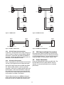
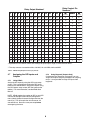
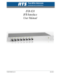
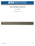
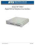
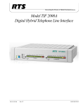
USER MANUAL
Model UIO-256
Universal Input/ Output Frame
9330-7499-000 Rev F, 02/2005
Proprietary Notice
The RTS product information and design disclosed
herein were originated by and are the property of Telex
Communications, Inc. Telex reserves all patent, proprietary design, manufacturing, reproduction, use and
sales rights thereto, and to any article disclosed therein,
except to the extent rights are expressly granted to
others.
Copyright Notice
Copyright© 2004 by Telex Communications, Inc. All
rights reserved. Reproduction in whole or in part
without prior written permission from Telex is prohibited.
Warranty Information
See enclosed warranty card.
Customer Support
Technical questions should be directed to:
Customer Service Department
RTS/Telex
12000 Portland Avenue South
Burnsville, MN 55337 U.S.A
Telephone:
(402) 467-5321
Fax:
(402) 467-3279
Factory Service (800) 553-5992
Return Shipping Instructions Procedure for
Returns
If a repair is necessary, contact the dealer where this
unit was purchased.
If repair through dealer is not possible, obtain a RETURN AUTHORIZATION from:
Customer Service Department
Telex Communications, Inc.
Telephone:
(402) 467-5321
Fax:
(402) 467-3279
Factory Service (800) 553-5992
Be prepared to provide the company name, address,
phone number, a person to contact regarding the repair,
the type and quantity of equipment, a description of the
problem, and the serial number(s).
Shipping to Manufacturer for Repair or Adjustment
All shipments of RTS products should be made via
United Parcel Service or the best available shipper,
prepaid. The equipment should be shipped in the
original packing carton; if that is not available, use any
suitable container that is rigid and of adequate size. If a
substitute container is used, the equipment should be
wrapped in paper and surrounded with at least four
inches of excelsior or similar shock-absorbing material.
All shipments must be sent to the following address and
must include the Return Authorization.
Factory Service Department
Telex Communications, Inc.
8601 Cornhusker Hwy
Lincoln, NE 68507 U.S.A
Attn: Service
Upon completion of any repair the equipment will be
returned via United Parcel Service or specified shipper,
collect.
What’s Included in this Box?
The UIO-256 shipping box should contain the following
items:
1
1
2
1
1
1
UIO-256 System
Power Cord (110V or 220V)
50-pin Telco Connector (no cable)
User Manual
Serial Cable
Warranty Card
If anything is missing or damaged, contact the shipper
or Telex immediately.
DO NOT RETURN ANY EQUIPMENT DIRECTLY TO
THE FACTORY WITHOUT FIRST OBTAINING A
RETURN AUTHORIZATION.
2
Contents
1. Introduction ......................................................................................................................................... 4
2. Description .......................................................................................................................................... 4
3. Theory of Operation ............................................................................................................................ 4
4. Installation ...........................................................................................................................................
4.1 Setting the DIP switches .............................................................................................................
4.1.1 System Firmware 9.2.1 or Newer .......................................................................................
4.1.2 System Firmware Older than 9.2.1 ....................................................................................
4.1.3 DIP Switch Functions .........................................................................................................
4.2 Voltage Section ...........................................................................................................................
4.3 Mounting .....................................................................................................................................
4.4 Multi-Drop Connections ...............................................................................................................
4.4.1 UIO-256 to ADAM System .................................................................................................
4.4.2 UIO-256 to ADAM CS System ...........................................................................................
4.4.3 UIO-256 Frame Interconnections .......................................................................................
4.4.4 UIO-256 to Zeus System....................................................................................................
4.5 GPI Output and Input Connections .............................................................................................
4.6 Power Connection .......................................................................................................................
4.7 Assigning the GPI Inputs and Outputs ........................................................................................
4.7.1 Using AZedit .......................................................................................................................
4.7.2 Using Keypanel (Outputs Only) ..........................................................................................
4
4
5
5
5
5
5
6
6
6
7
7
7
7
8
8
8
5. Operation............................................................................................................................................. 9
5.1 Status Indicators ......................................................................................................................... 9
5.2 UIO-256 Frame Reset ................................................................................................................. 9
5.3 Fuse Replacement .................................................................................................................... 10
6. Specifications .................................................................................................................................... 10
3
Figure 1. UIO-256 Front and Rear Panel Features
1.
Introduction
This manual describes the installation, programming,
and operating procedures for the RTS Model UIO-256
Universal Input/Output Frame. Since the UIO-256
inputs and outputs are generally assigned using AZedit.
For more information on AZedit, refer to the AZedit User
Manual (9350-7532-000).
2.
4.
Installation
4.1
Setting the DIP switches
Description
Each UIO-256 provides 16 GPI inputs and 16 GPI
outputs. The GPI inputs can be set up as remotely
controlled keypanel keys to activate intercom ports,
party lines, GPI outputs, etc. within the intercom system. The GPI outputs are typically assigned for activation from keypanel keys. They can be used to control
lighting or to key remote transmitters, paging systems,
etc.
3.
GPI inputs are connected via a 50-pin telco connector
on the back of the UIO-256. Each input requires =5 to
+18 VDC for activation. The positive input and common
connections may be provided from a remote source.
Or, +18 VDC is supplied at the connector by the UIO256, and may be used for input activation, with the user
supplying the external switch.
Theory of Operation
The UIO-256 exchanges control signals with the
intercom system via an RS-485 data connection.
Multiple UIO-256’s may also be interconnected using a
multi-drop configuration. Note, the multi-drop configuration requires version 2 of the UIO-256 firmware.
There are two banks of DIP switches on the back panel.
Only SW1 is currently used. There are slight differences between how UIO-256 units are configured
based on the version of firmware they are programmed
with and the ADAM or ADAM CS Firmware version.
The current shipping version of the firmware is Version
2. If the intercom system (ADAM or ADAM CS ) has
Firmware version 9.2.1 or later, Version 2 of the UIO256 firmware MUST be used. If the firmware in the
intercom system is older than 9.2.1, then either Version
1 or 2 of the UIO-256 firmware may be used.
4
4.2
4.1.1 System Firmware 9.2.1 or Newer
The UIO-256 must be configured to work in Multi-Drop
mode. Set DIP switch 1-2 to the CLOSED position. Up
to 16 UIO-256 frames are allowed to be connected
together.
Voltage Section
Set the 110/220 VAC selector according to local power
standards.
4.3
Mounting
UIO-256 Frames are generally mounted in the front of
an equipment rack near a Master Controller Breakout
Panel for ADAM intercom systems or near the matrix
frame for ADAM CS intercom systems. When positioning a UIO-256, consideration should be given to the
visibility of the front panel status indicators and access
to the reset switch. Also, consider access to the rear
panel for fuse replacement or changes to the DIP switch
settings, etc. There are no ventilation requirements.
4.1.2 System Firmware Older than 9.2.1
The UIO-256 must be configured to work in Token Ring
mode. Set DIP switch 1-2 to the OPEN position. Up to
four UIO-256 frames are allowed to be connected
together.
4.1.3 DIP Switch Functions
SW1-1: Diagnostics mode. Leave in OPEN
position for normal operation. If open, GPI outputs
operate normally. If closed, GPI outputs track the
corresponding GPI inputs
SW1-2: Communications Mode
Open = Token Ring
Closed = Multi-Drop (default)
SW1-3: Unused. Leave in OPEN position.
SW1-4 to SW1-7: Frame number
SW1-8: Baud rate for communication between
UIO-256 and the intercom system. Must be closed
(76.8K baud).
FRAME
NUMBER
SW1-1
SW1-2
SW1-3
SW1-4
SW1-5
SW1-6
SW1-7
SW1-8
GPI INPUT /
OUTPUT
NUMBERS
1
Open
Open/Closed
see text
Open
Open
Open
Open
Open
Closed
001-016
2
Open
Open/Closed
see text
Open
Closed
Open
Open
Open
Closed
017-032
3
Open
Open/Closed
see text
Open
Open
Closed
Open
Open
Closed
033-048
4
Open
Open/Closed
see text
Open
Closed
Closed
Open
Open
Closed
049-064
5*
Open
Closed
Open
Open
Open
Closed
Open
Closed
065-080
6*
Open
Closed
Open
Closed
Open
Closed
Open
Closed
081-096
7*
Open
Closed
Open
Open
Closed
Closed
Open
Closed
097-112
8*
Open
Closed
Open
Closed
Closed
Closed
Open
Closed
113-128
9*
Open
Closed
Open
Open
Open
Open
Closed
Closed
129-144
10*
Open
Closed
Open
Closed
Open
Open
Closed
Closed
145-160
11*
Open
Closed
Open
Open
Closed
Open
Closed
Closed
161-176
12*
Open
Closed
Open
Closed
Closed
Open
Closed
Closed
177-192
13*
Open
Closed
Open
Open
Open
Closed
Closed
Closed
193-208
14*
Open
Closed
Open
Closed
Open
Closed
Closed
Closed
209-224
15*
Open
Closed
Open
Open
Closed
Closed
Closed
Closed
225-240
16*
Open
Closed
Open
Closed
Closed
Closed
Closed
Closed
241-256
NOTE: Frame numbers 5-16 are possible only when using multi-drop mode.
Table 1. UIO-256 DIP Switch 1 Configuration.
5
SW1
SW1
Open
Open
Closed 1 2 3 4 5 6 7 8
GPI OUT
1-16
Punch
Block
CONNECTION TO
INTERCOM SYSTEM
XCP-ADAM-MC,
XCP-ADAM-MCJ3
or
ADAM CS, J902
or
ZEUS, J26
GPI IN
1-16
Punch
Block
50-Pin
50-Pin
J7
UIO-256 #2
In / Out 17-32
J2
J3
J4
J3
J4
J4
J3
J4
J3
UIO-256 #3
IN / OUT 33-48
J2
J7
J5
50-Pin
50-Pin
GPI OUT
49-64
J7
J5
Punch
Block
GPI IN
49-64
Punch
Block
PAP/LCP-102 Panels
(15 units max)
J5
UIO-256 #4
IN / OUT 49-64
J2
GPI IN
17-32
Punch
Block
50-Pin
J7
UIO-256 #1
In / Out 1-16
J2
GPI OUT
17-32
Punch
Block
50-Pin
J5
9-Pin
Closed 1 2 3 4 5 6 7 8
50-Pin
50-Pin
Punch
Block
Punch
Block
GPI OUT
33-48
GPI IN
33-48
SW1
SW1
Open
Open
Closed 1 2 3 4 5 6 7 8
Closed 1 2 3 4 5 6 7 8
Figure 2. Multi-Drop Connections
4.4
Multi-Drop Connections
See Figure 2 for typical connections and DIP settings.
To connect a Program Assign Panel or additional UIO256 units, construct a “Y” cable as shown in Figure 4.
This cable replaces the supplied 9-pin cable.
4.4.1 UIO-256 to ADAM System
Connect the end of the 9-pin cable marked ADAM
System to J3 of the XCP-ADAM-MC Master Controller
Breakout Panel. Connect the end marked UIO-256 to
J2 of the UIO-256 Frame. If you need a longer cable,
you can construct one using the wiring diagram in
Figure 5.
4.4.2 UIO-256 to ADAM CS System
For ADAM CS intercom systems, the connector marked
“ADAM System” on the 9-pin cable must be replaced
with the provided female connector. Disconnect the
wires and reconnect them to the same pin numbers.
After modifying the cable, connect the newly attached
female connector to J902 of the ADAM CS frame.
Connect the end marked “UIO-256” to J2 of the UIO256 frame. If you need a longer cable, you can construct one using the wiring diagram in Figure 6.
6
DE-9S
(Female)
DE-9P
(Male)
DE-9P
(Male)
DE-9P
(Male)
6
1
6
1
1
2
1
2
2
TO ADAM CS, J902
2
TO XPC-ADAM-MC, J3
TO: UIO-256, J2
DE-9P
(Male)
DE-9P
(Male)
7
7
2
2
1
1
TO: PAP-940,
PAP-951, OR PAP-952
TO: PAP-940,
PAP-951, OR PAP-952
DE-9P
(Male)
DE-9P
(Male)
6
6
1
1
2
2
TO: PAP-950-50
TO: PAP-950-50
Figure 4. ADAM CS Y-Cable
Figure 3. ADAM Y-Cable
DE-9P
(Male)
TO: UIO-256, J2
DE-9P
(Male)
DE-9S
(Female)
DE-9P
(Male)
6
1
6
1
1
2
1
2
2
TO XCP-ADAM-MC, J3
2
TO UIO-256, J2
TO ADAM CS, J902
Figure 5. ADAM to UIO-256 Cable
Figure 6. ADAM CS to UIO-256 Cable
4.4.3 UIO-256 Frame Interconnections
If more than one UIO-256 frame is used, construct a Ycable as shown in Figure 3 or 4 with additional DB-9S
connectors in parallel with the ADAM and ADAM CS
connector. Connect the addition connectors to the J2
connector on each additional UIO-256.
4.5
TO UIO-256, J2
GPI Output and Input Connections
Use 50-pin Telco cables to connect from the GPI input
and output connectors to each UIO-256 to punch blocks
or similar breakout devices. Pin-outs for the connectors
and punch blocks are summarized in Tables 2 and 3.
4.6
4.4.4 UIO-256 to Zeus System
Zeus is compatible only with UIO-256 firmware Version
2 or later, and it supports only multi-drop connection.
Power Connection
Plug in the supplied power cord for each UIO-256. The
UIO-256 does not have a power ON/OFF switch or
indicator, so it may be convenient to use a switched
power outlet.
Use the DIP switch information for ADAM and ADAM
CS. Make sure DIP switch 2 is set for “multi-drop”
connection. Also, Zeus is limited to 64 GPI inputs and
64 GPI outputs. Since each UIO-256 has 16 of each,
this means that you can only use up to four UIO-256
frames with Zeus. When setting frame numbers, only
frame numbers 1 through 4 are allowed.
Treat the Zeus the same as an ADAM for wiring purposes, except connect to J26 on the Zeus back panel
instead of J3 of the XCP-ADAM -MC breakout panel.
7
Relay Contact Pin
Numbers**
Relay Output Numbers*
1
2
3
4
5
6
7
8
9
10
10
11
11
12
12
13
13
14
14
15
15
16
16
NC
NC
Co n t ac t
Co m m o n
NO
NO
Co n t ac t
1
17
33
49
65
81
97
113
129
145
161
177
193
209
22 5
241
38
13
40
2
18
34
50
66
82
98
114
130
14 6
162
178
194
210
226
24 2
39
14
15
3
19
35
51
67
83
99
115
131
147
163
179
195
211
227
243
41
16
43
4
20
36
52
68
84
100
116
132
148
16 4
180
196
212
22 8
244
42
17
18
5
21
37
53
69
85
101
117
133
149
165
18 1
197
213
229
245
44
19
46
6
22
38
54
70
86
102
118
134
150
166
18 2
198
214
23 0
246
45
20
21
7
23
39
55
71
87
103
119
135
151
16 7
18 3
199
215
231
247
47
22
49
8
24
40
56
72
88
104
120
136
15 2
16 8
184
200
216
232
248
48
23
24
9
25
41
57
73
89
105
121
137
153
169
185
201
217
233
249
26
1
28
10
26
42
58
74
90
106
122
138
154
17 0
186
202
21 8
23 4
250
27
2
3
11
27
43
59
75
91
107
123
139
155
171
187
203
21 9
235
251
29
4
31
12
28
44
60
76
92
108
124
140
156
172
188
204
220
236
252
30
5
6
13
29
45
61
77
93
109
125
141
157
173
189
205
221
237
253
32
7
34
14
30
46
62
78
94
110
126
142
158
17 4
190
206
222
238
254
33
8
9
15
31
47
63
79
95
111
127
143
159
17 5
191
207
223
239
255
35
10
37
16
32
48
64
80
96
112
128
144
160
176
19 2
20 8
224
240
256
36
11
12
* Dependent on UIO-256 DIP switch SW1 settings for Input/Output range as summarized in Table 1.
** The relay contacts are rated for 0.5A at 120 VAC; 1A at 24 VDC; 0.3A at 60 VDC
Table 3. UIO-256 Relay Output Connector (J5) Pinouts.
4.7
Assigning the GPI Inputs and
Outputs
4.7.1 Using AZedit
Assign the GPI inputs by using the GPI Inputs setup
screen. This is accessible by clicking the GPI Inputs
button on the AZedit toolbar. Assign GPI outputs using
the GPI Outputs setup screen (GPI Out button on the
toolbar). For more information, see the AZedit User
Manual.
4.7.2 Using Keypanel (Outputs Only)
On keypanels that permit key assignment, you can
assign GPI outputs using the procedures for assigning
relays. It is not possible to assign GPI inputs from
keypanels.
NOTE: AZedit requires the number of GPI Ins and GPI
Outs be set throughout the Intercom Configuration
menu (select Options>Intercom Configuration from the
menu bar). This will require the unit to be reset. All
data will be lost. Be sure to save your setup before
reconfiguring the frame.
8
5.
Operation
5.2
UIO-256 Frame Reset
The UIO-256 firmware has been designed to detect and
recover from errors caused by such things as lost or
bad data packets. However, in the extremely unlikely
event the unit stops functioning during operation, try
pressing the reset switch on the front panel of the UIO256.5.3 Fuse Replacement
The fuse is accessible on the rear panel power module
of the UIO-256. Remove the power cord from the
power module and free the fuse cartridge as shown
Figure 7. Be sure
5.1
Status Indicators
Activating a keypanel key that is assigned to a GPI
output will cause the appropriate OUTPUT STATUS
indicator on the UIO-256 front panel to light, and the
relay contact for that output will activate. Activating a
GPI input from an external device will cause the appropriate INPUT STATUS indicator to light, and the
keypanel key assignment or other device within the
intercom system that is assigned to that GPI input will
activate.
When using multiple UIO-256 frames, the status of the
first 16 GPI output and inputs will be indicated by the
status indicators on the first UIO-256. The status
indicators on the second UIO-256 will indicate status of
outputs and inputs 17 to 32 and so forth as summarized
in Table 1.
GPI Input Pin
Numbers**
Relay Input Numbers*
1
2
3
4
5
6
7
8
9
10
10
11
11
12
12
13
13
14
14
15
15
16
16
- I nput
+ I nput (5-18VDC)
1
17 33
49
65
81
97
113
129
145
16 1
17 7
193
209
225
241
9
34
2
18 34
50
66
82
98
114
130
14 6
16 2
178
19 4
2 10
2 26
24 2
10
35
3
19 35
51
67
83
99
115
131
14 7
16 3
179
19 5
211
2 27
24 3
11
36
4
20
36
52
68
84
100
116
132
14 8
16 4
180
19 6
2 12
2 28
24 4
12
37
5
2 1 37
53
69
85
101
117
133
14 9
16 5
181
197
2 13
22 9
24 5
13
38
6
22
38
54
70
86
102
118
134
150
16 6
18 2
198
2 14
2 30
24 6
14
39
7
23
39
55
71
87
103
119
135
151
16 7
183
19 9
2 15
231
247
15
40
8
24 4 0
56
72
88
104
120
136
152
168
18 4
2 00
216
2 32
24 8
16
41
9
25
41
57
73
89
105
121
137
153
169
18 5
201
2 17
23 3
24 9
1
26
10 26 42
58
74
90
106
122
138
15 4
17 0
186
2 02
218
23 4
25 0
2
27
11 27 43
59
75
91
107
123
139
15 5
171
18 7
2 03
219
23 5
251
3
28
12 28 44
60
76
92
108
124
140
156
172
188
2 04
22 0
236
25 2
4
29
13 29 45
61
77
93
109
125
141
15 7
173
189
2 05
221
23 7
25 3
5
30
14 30 46
62
78
94
110
126
142
158
174
190
2 06
22 2
238
25 4
6
31
15
31 47
63
79
95
111
127
143
15 9
17 5
191
207
22 3
239
25 5
7
32
16 32 48
64
80
96
112
128
144
160
176
192
2 08
22 4
240
25 6
8
33
* Dependent on UIO-256 DIP switch SW1 settings for Input/Output range as summarized in Table 1.
**Inputs will sink 100 mA maximum at a maximum input voltage of +18 VDC. For operation from an external DC
voltage source, connect the external control voltage to the positive “+” input pin, and connect the external common
to the negative “-” input pin. The UIO-256 also has an internal 18 VDC source, which is available at pins 18 and 22.
Ground is available at pins 24 and 25. To use the internal 18 VDC source, ground the “-” input for the desired
control input, then use an external switch to connect from the 18 VDC internal source to the “+” input pin.
Table 3. UIO-256 GPI Input Connector (J7) Pinouts
9
5.3
Fuse Replacement
The fuse is accessible on the rear panel power module
of the UIO-256. Remove the power cord from the
power module and free the fuse cartridge as shown
Figure 7. Be sure to replace the fuse with a fuse of the
same rating and type.
6.
Specifications
Power
110/220 VAC, 50/60 Hz (selectable via backpanel)
Dimensions
1RU High x 7” (178mm) deep behind front panel
GPI Inputs
Type: Optically coupled
0
22
11
USE ONLY WITH A 250V FUSE
Input Requirements: 5-18 VDC
GPI Outputs
0
Type: DPDT Relays with common, normal-open
and normal -closed contacts
Contact Ratings: 0.5A at 120 VAC; 1A at 24 VDC;
0.3A at 60 VDC
Figure 7. Fuse Replacement
10
11
Telex Communications, Inc. • 12000 Portland Avenue South • Burnsville, MN 55337