1
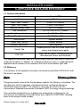
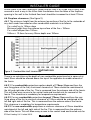
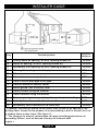
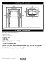
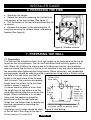
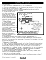
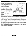
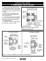
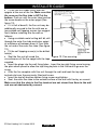
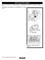
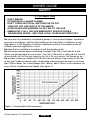
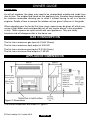
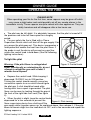
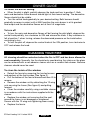
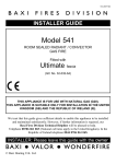
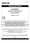
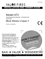
5115716/05 INSTALLATION AND OWNER GUIDE Model 473 ROOM SEALED RADIANT / CONVECTOR GAS FIRE Black Beauty Unigas II (GC No. 32-810-58) We trust that this guide gives sufficient details to enable this appliance to be installed and maintained satisfactorily. However, if further information is required, our Valor Fires Technical Helpline will be pleased to help. Telephone 0844 8711 565 (National call rates apply in the United Kingdom). In the Republic of Ireland Telephone 0044 844 8711 565. INSTALLER: Please leave this guide with the owner © Baxi Heating U.K. Limited 2010. THIS APPLIANCE IS FOR USE WITH NATURAL GAS (G20). UNDER NO CIRCUMSTANCES IS THIS APPLIANCE TO BE CONVERTED TO LPG. AN LPG CONVERSION KIT DOES NOT EXIST FOR THIS APPLIANCE THIS APPLIANCE IS SUITABLE ONLY FOR INSTALLATION IN THE UNITED KINGDOM (GB) AND THE REPUBLIC OF IRELAND (IE). Baxi Heating U.K. Limited 2010. All rights reserved. No part of this publication may be reproduced in any material form (including photocopying), stored in any medium by electronic means (including in any retrieval system or database) or transmitted, in any form or by any means, whether electronic, mechanical, recording or otherwise, without the prior written permission of the copyright owner. Applications for the copyright owner's permission to reproduce any part of this publication should be made, giving details of the proposed use, to the following address: The Company Secretary, Baxi Heating UK Limited, Brooks House, Coventry Road, Warwick, CV34 4LL Warning: Any person who does any unauthorised act in relation to a copyright work may be liable to criminal prosecution and civil claims for damages. Valor Fires, Erdington, Birmingham B24 9QP www.firesandstoves.co.uk Because our policy is one of constant development and improvement, details may vary slightly from those given in this publication © Baxi Heating U.K. Limited 2010. Page 2 Safety First. Valor Fires fires are CE Approved and designed to meet the appropriate British Standards and Safety Marks. Quality and Excellence. All Valor Fires fires are manufactured to the highest standards of quality and excellence and are manufactured under a BS EN ISO 9001 quality system accepted by the British Standards Institute. The Highest Standards Valor Fires is a member of SBGI and HHIC (Heating and Hot water Industry Council) that work to ensure high standards of safety, quality and performance. Careful Installation This gas fire must be installed by a competent GAS SAFE REGISTER engineer (GAS SAFE REGISTER or CORGI engineer outside of UK) in accordance with our installer guide and should not be fitted directly on to a carpet or floor of combustible material. © Baxi Heating U.K. Limited 2010. Page 3 INSTALLER GUIDE INSTALLER GUIDE FOR OWNER GUIDE SEE PAGES 31 TO 43 © Baxi Heating U.K. Limited 2010. Page 4 INSTALLER GUIDE CONTENTS Section Heading Page INSTALLER GUIDE OWNER GUIDE 4 - 30 31 - 43 1. SAFETY 2. ACCESSORY LIST 3. APPLIANCE DATA AND EFFICIENCY 3.1 General information. 3.2 Efficiency. 4. GENERAL INSTALLATION REQUIREMENTS 4.1 Regulations, Standards and Law. 4.1.1 Installations into timber framed buildings. 4.2 Ventilation requirements. 4.3 Fireguard requirements. 4.4 Room considerations. 4.5 The hearth. 4.6 Fireplace clearances 4.7 Wall thickness and material. 4.8 Flue hole size and location. 4.9 Flue terminal guard. 5. PACK CONTENTS 6. PREPARING THE FIRE 7. PREPARING THE WALL 7.1 Preparation 7.2 Core Drilling 7.3 Hammer & Chisel Cutting 7.4 Leaving a Hole, Building under Construction 7.5 Combustible Walls (Wood, Fibreboard, Plasterboard etc.) 8. PREPARING THE FLUE UNIT 9. TERMINAL GUARD FITTING 7 7 8 8 8 9 9 9 10 10 10 10 11 12 12 12 14 15 15 15 16 16 17 17 19 21 Continued on next page © Baxi Heating U.K. Limited 2010. Page 5 INSTALLER GUIDE CONTENTS (Continued) Section Heading Page 10. CHECK IGNITION SPARK 11. CONNECTING THE GAS SUPPLY 12. FITTING THE CERAMIC COAL EFFECT 13. CHECK APPLIANCE OPERATION 14. CHECK THE REFERENCE PRESSURE 15. REPLACING THE FASCIA 16. FINAL REVIEW 17. SERVICING AND PARTS REPLACEMENT 17.1 To remove the fascia. 17.2 To remove the window unit. 17.3 To remove the ceramic fuel effect. 17.4 To remove the burner(s). 17.5 To remove the injectors(s). 17.6 To remove the thermocouple. 17.7 To remove the electrode pin. 17.8 To remove the pilot pipe and pilot injector. 17.9 To remove the gas tap and piezo unit. 17.10 To remove the piezo generator. 17.11 To grease the control tap. © Baxi Heating U.K. Limited 2010. Page 6 21 22 23 26 26 27 27 28 28 28 28 29 29 29 29 29 30 30 30 INSTALLER GUIDE 1. SAFETY Installer Before continuing any further with the installation of this appliance please read the following guide to manual handling: The lifting weight of the appliance is 26.2 kg. One person should be sufficient to lift the fire. If for any reason this weight is considered too heavy then obtain assistance. When lifting always keep your back straight. Bend your legs and not your back. Avoid twisting at the waist. It is better to reposition your feet. Avoid upper body/top heavy bending. Do not lean forward or sideways whilst handling the fire. Always grip with the palm of the hand. Do not use the tips of fingers for support. Always keep the fire as close to the body as possible. This will minimise the cantilever action. Use gloves to provide additional grip. Always use assistance if required. This product uses fuel effect pieces and gaskets containing Refractory Ceramic Fibres (RCF), which are man-made vitreous silicate fibres. Excessive exposure to these materials may cause irritation to eyes, skin and respiratory tract. Consequently, it is important to take care when handling these articles to ensure that the release of dust is kept to a minimum. To ensure that the release of fibres from these RCF articles is kept to a minimum, during installation and servicing we recommend that you use a HEPA filtered vacuum to remove any dust and soot accumulated in and around the fire before and after working on the fire. When replacing these articles we recommend that the replaced items are not broken up, but are sealed within a heavy duty polythene bag, clearly labelled as RCF waste. RCF waste is classed as a stable, non-reactive hazardous waste and may be disposed at a landfill licenced to accept such waste. Protective clothing is not required when handling these articles, but we recommend the use of suitable gloves to prevent irritation. We also recommend you follow the normal hygiene rules of not smoking, eating or drinking in the work area and always wash your hands before eating or drinking. This appliance does not contain any component manufactured from asbestos or asbestos related products. 2. ACCESSORY LIST The following accessories are available:Description Part Number Terminal guard © Baxi Heating U.K. Limited 2010. 516539 Page 7 INSTALLER GUIDE 3. APPLIANCE DATA AND EFFICIENCY 3.1 General information. Gas Natural (G20) Inlet Pressure 20mbar Input - Max. (Gross) 4.9kW (16,719Btu/h) Input - Min. (Gross) 2.2kW (7,507Btu/h) Pressure Setting (Cold) 18.2 + 0.75mbar Gas Connection RP 1/4 (1/4in. B.S.P) Female. Main Burner Injector Cat. 960 Size 240. Flame Effect Burner Injector Cat. 960 Size 130. Main Burner: Simplex aerated. Flame Effect Burner: Simplex aerated. Aeration Adjustment: None required. Control Tap: Variable position fitted with flame supervision device and integral piezo igniter. Pilot Unit: Right side of firebox. Combined pilot jet thermocouple sensor and electrode. The appliance information label is at the left side of the rear case and is visible after removing the fascia. In addition, for customers reference, there is a label giving the appliance serial number on the outside of the fascia at the bottom right side. 3.2 Efficiency. The efficiency of this appliance has been measured as specified in BS EN 613 and the result is as below : Model 473 Efficiency % (Gross) 72 The gross calorific value of the fuel has been used for this efficiency calculation. The test data from which it has been calculated has been certified by Advantica Certification services (0087). The efficiency value may be used in the UK Government's Standard Assessment Procedure (SAP) for energy rating of dwellings. The convertion of net efficiency to gross was achieved by multiplying the net efficiency by the following conversion factor from Table E3 of SAP 2005, rounding down to the nearest whole number. © Baxi Heating U.K. Limited 2010. Page 8 INSTALLER GUIDE Gas Conversion factor from net to gross efficiency Natural Gas 0.901 4. GENERAL INSTALLATION REQUIREMENTS 4.1 Regulations, Standards and Law. The installation must be in accordance with this guide. For the user’s protection, in the United Kingdom it is the law that all gas appliances are installed by competent persons in accordance with the current edition of the Gas Safety (Installation and Use) Regulations. Failure to install the appliance correctly could lead to prosecution. GAS SAFE REGISTER and CORGI require their members to work to recognised standards. In the United Kingdom the installation must also be in accordance with: All the relevant parts of local regulations. All relevant codes of practice. The relevant parts of the current editions of the following British Standards:BS 5440 Part 1 Installation of flues. BS 5871 Part 1 Installation – Gas fires BS 6891 Gas pipework installation In the republic of Ireland the installation must also conform to: a) The relevant parts of the current edition of IS 813 “Domestic Gas Installations” b) All applicable national and local rules in force. In England and Wales, the current edition of the Building Regulations issued by the Department of the Environment and the Welsh Office. In Scotland, the current edition of the Building Standards (Scotland) Regulations issued by the Scottish Executive. In Northern Ireland, the current edition of the Building regulations (Northern Ireland) issued by the Department of the Environment for Northern Ireland. In the Republic of Ireland the installation must be carried out by a competent person and also conform to the relevant parts of: a) The current edition of IS 813 “Domestic Gas Installations” b) All relevant national and local rules in force. Where no specific instructions are given, reference should be made to the relevant British Standard Code of Practice. 4.1.1 Installations into timber framed buildings. Installation to a timber-framed building should be in accordance with the relevant sections of The Institute of Gas Engineers publication IGE/UP/7 “Gas installations in timber frame buildings”. Please note that advice should be sought before installing in a timber frame building since the alterations required may nullify any NHBC cover relating to the property. If in doubt, guidance should be requested from your local authority planning or building department. © Baxi Heating U.K. Limited 2010. Page 9 INSTALLER GUIDE 4.2 Ventilation requirements. No special ventilation bricks or vents into the room containing the appliance are required. 4.3 Fireguard requirements. A fireguard complying with BS 8423 should be fitted for the protection of young children, the elderly, the infirm and pet animals. Although this fire conforms to all the applicable standards, it is a heating appliance and certain parts of its surface will become hot. 4.4 Room considerations. It is advisable that combustible fabrics such as curtains are not fitted above the fire. If, however, this is unavoidable, a clearance of at least 150mm must be maintained from the extreme bottom edge of the fabric to the extreme top surface of the fire. 4.5 The hearth. The appliance can be installed with or without a non-combustible hearth. If a noncombustible hearth is installed, there must be a minimum clearance from the top surface of the hearth to the absolute bottom of the appliance of 18mm (See figure 1). The hearth must be at least 700mm wide x 300mm deep. The non-combustible hearth material must be at least 12mm thick. Its top surface should be preferably 50mm above floor level to discourage the placing of carpets or rugs over it. If the appliance is not installed with a hearth meeting the above conditions, the minimum distance from the top surface of the finished floor covering (including any carpet etc.) to the absolute bottom of the appliance must be at least 40mm (See figure 1). Figure 1. Dimensions © Baxi Heating U.K. Limited 2010. Page 10 INSTALLER GUIDE Where there is no floor covering or carpet and the floor is of a type that is likely to be covered in such a way in the future then the distance from the base of the fireplace opening in the wall to the finished floor level should be increased to at least 115mm. 4.6 Fireplace clearances (See figure 2). 4.6.1 The minimum height from the extreme top surface of the fire to the underside of any shelf made from wood or other combustible materials is as follows: For a shelf up to 150mm deep Minimum height from the extreme top surface of the fire = 150mm. For a shelf deeper than 150mm 150mm + 12.5mm for every 25mm depth over 150mm. figure 2. Combustible shelf clearances. There is no restriction on the depth of non-combustible projections but a space of at least 30mm should be allowed above the top of the appliance to enable removal of the fascia. 4.6.2.1 For combustible projections up to a depth of 178mm (Measured from the rear fixing plane of the fire) a minimum clearance of 75mm should be maintained at the left and right side of the fire. This is measured from the extreme side of the fascia. This will allow easy access to the control knob and knurled nuts for removal of the fascia. This clearance is mandatory for temperature requirements. 4.6.2.2 For any combustible projections beyond 178mm (Measured from the rear fixing plane of the fire) a minimum clearance of 100mm should be maintained at the left and right side of the fire. This is measured from the extreme side of the fascia. This clearance is mandatory for temperature requirements. 4.6.2.3 For non-combustible projections a minimum clearance of 75mm should be maintained at the left and right side of the fire. This is measured from the extreme side of the fascia. This will allow easy access to the control knob and knurled nuts for © Baxi Heating U.K. Limited 2010. Page 11 INSTALLER GUIDE removal of the fascia. If the fireplace opening is greater than the acceptable dimensions given in this guide, do not use the back of a fire surround or marble to reduce the opening. This may cause cracking of the surround back or marble. 4.7 Wall thickness and material. Wall thickness: Minimum wall thickness 102mm (4in.). Maximum wall thickness 660mm (26in.). This fire is suitable for use with combustible walls provided that there is no combustible material or combustible cladding in the area indicated on the wall fixing template. Please note that soft wall coverings (e.g. embossed vinyls etc.) are easily affected by heat. They may therefore, scorch or become discoloured when close to a heating appliance. Please bear this in mind when installing. 4.8 Flue hole size and location. A hole 152mm (6in) is required through the wall for the flue unit. The minimum height of the hole centre is shown in figure 1 and on the wall fixing template. Minimum allowable distances from the terminal are shown figure 3. 4.9 Flue terminal guard. In England and Wales the Building Regulations require a terminal guard to be fitted if the terminal could come into contact with people near the building or be subject to damage. Fitting a terminal guard is recommended where contact with or damage to the terminal is possible even if regulations do not demand it. A suitable guard - Part No. 516539 - is available. © Baxi Heating U.K. Limited 2010. Page 12 INSTALLER GUIDE Key Terminal position Minimum distance. A* Directly below an opening, air brick, opening window etc. 300mm B* Above an opening, air brick, opening window etc. 300mm C* Horizontally to an opening, air brick, opening window etc. 300mm D Below gutters, soil pipes or drain pipes. 300mm E Below eaves. 300mm F Below balconies or car port roof. 600mm G From a vertical drain pipe or soil pipe. 300mm H** From an internal or external corner. 600mm I Above ground, roof or balcony level. 300mm J From a surface facing the terminal. 600mm K From a terminal facing the terminal. 600mm L From an opening in a car port (e.g. door, window) into dwelling. 1200mm M Vertically from a terminal on the same wall. 1500mm N Horizontally from a terminal on the same wall. 300mm *In addition, the terminal should not be nearer than 300mm to an opening in the building fabric formed for the purpose of accommodating a built-in element such as a window frame or door frame (See figure 4). ** The reference to external corners does not apply to building protrusions not exceeding 450mm, such as disused chimneys on external walls. Figure 3. © Baxi Heating U.K. Limited 2010. Page 13 INSTALLER GUIDE Figure 4. 5. PACK CONTENTS The carton contains the following:1 1 4 1 1 1 1 1 Fire assembly. Ceramic fuel base. Ceramic coals. Flue unit. Inlet elbow. Pack of fixing screws and wall plugs. Wall fixing template. Length of flue sealing tape. Remove all the items carefully to prevent damage. Some items may be contained in the packaging fitments - Examine the packaging carefully before discarding. Check that all the items are present and undamaged. © Baxi Heating U.K. Limited 2010. Page 14 INSTALLER GUIDE 6. PREPARING THE FIRE Stand the fire upright. Detach the fascia by removing the knurled nuts and washers at the fascia sides (See figure 1). Pull the bottom of the fascia forward and then lift to remove. Remove the window unit by detaching the 12 wing nuts securing the window frame and pulling forward (See figure 5). Figure 5. Window removal 7. PREPARING THE WALL 7.1 Preparation The flue must be installed so that it is at right angles to the back panel of the fire all round the flue circumference. The fire itself should be fitted vertically against a flat wall. Where this is difficult to achieve due to building inaccuracies care should be taken to ensure that the back of the fire is not stressed in any way due to distortion of the assembly when tightening the fixing screws. Where necessary, non-combustible packing pieces should be used to provide a satisfactory fixing surface. Before cutting the hole in the wall make sure that the height to the top surface of the finished floor is known. The minimum acceptable height from this surface to the flue hole centre is shown in figure 6. If a loose hearth or plinth is to be used, the height from its top surface must be used when determining the minimum flue height. Where installation is to a timber frame wall, the appliance should be positioned so that the right side wall fixings are into timber studs to absorb any pressure generated by operating the control knob. Proprietary cavity fixings should be used Figure 6. Wall drilling. at the left side if the fixing at this side is © Baxi Heating U.K. Limited 2010. Page 15 INSTALLER GUIDE into plasterboard. Place dust sheets on the floor and over any furnishings etc. Place the template against the wall. Make sure that the centre of the flue hole is not less than the minimum shown in figure 6. Pierce the centre of the screw fixing holes and the flue hole and mark the positions on the wall. Remove the template. Cut the hole for the flue unit. Make sure that it is straight and level. Though a hammer and chisel can be used, using a core drill is by far the quickest and simplest method for normal brickwork. 7.2 Core Drilling Drill a pilot hole through the wall. Inspect the hole to ensure that it is in the brickwork and not in mortar. If it is in mortar, it is advisable to reposition the hole approximately 25mm away (making sure that the minimum side clearances and height are complied with). Figure 7. Removal of combustible cladding. Remember to reposition the screw fixing holes. Drill the flue hole with a 6in. (152mm) core drill. Where practical, it is recommended that the hole is drilled from inside the building to about half the wall depth with the remainder drilled from outside. This ensures that the edges of the hole are clean on both sides. 7.3 Hammer & Chisel Cutting Mark a 152mm (6in) diameter circle for the flue hole. Chisel out the area marked. It may be necessary to make good both the internal and external wall faces. To achieve a neat finish and to make any future removal of the flue unit easier, it is recommended that a cardboard cylinder is formed around the flue unit and inserted in the hole while making good. Remove the cardboard cylinder after making good. Recheck the screw fixing holes relative to the flue hole. Drill the four fixing holes to a minimum depth of 42mm using a suitably sized masonry drill for the wall plugs supplied. Insert the four wall plugs supplied. Remove any combustible wall cladding material from the area shown in figure 7. © Baxi Heating U.K. Limited 2010. Page 16 INSTALLER GUIDE 7.4 Leaving a Hole, Building under Construction It will be convenient to use a non-corrosive metal tube 160mm diameter built into the wall at the correct position for the flue unit. 7.5 Combustible Walls (Wood, Fibreboard, Plasterboard etc.) Building regulations require that the inlet and outlet ducts and terminal bust not be closer than 25mm to combustible material. If the heater is to be mounted on to a plasterboard wall that has a wooden frame behind it then the integrity and ability of the wall to carry the weight of the appliance must be confirmed. It is important that any vapour control barrier is not damaged, and that the structural members of the house are not damaged. We recommend a minimum 12mm thick plasterboard. Mark out and cut a hole 202mm diameter through the combustible part of the wall. A 152mm diameter hole can be cut through non-combustible parts of the wall. A 152mm diameter hole can be cut through non-combustible parts of the wall (See figure 8). Figure 8. Timber frame wall preparation. © Baxi Heating U.K. Limited 2010. Page 17 INSTALLER GUIDE Cover the hole with a square sheet steel plate 500mm x 235mm with a 152mm diameter hole cut out of the centre (See figure 9). The steel should be not less than 1.5mm thick. Fix with suitable screws and plugs. Where the whole wall is of combustible material, a non-corrosive plate 455mm x 455mm with a 152mm diameter hole in the centre must be fitted to the outer wall. The hole through the wall should be lined with a non-corrosive metal tube 202mm diameter. Cut the Flue Hole -Timber Frame Buildings Figure 9. Wall cover plate. Drill the pilot hole and hole in the outer wall as section 7.5. Since the flue will pass through combustible material in the inner leaf of the wall, a non-combustible sleeve 203mm (8in.) diameter will be required round the flue (See figure 8). Cut a hole through the inner leaf to accommodate a non-combustible sleeve 203mm (8in.) outside diameter. To minimise the effect of breaking through the vapour control layer (VCL), if possible, cut the hole approximately 10mm undersize so that the sleeve will be forced through the layer. A recommended technique for cutting the inner leaf is shown in figure 9. Fit the non-combustible sleeve to the inner leaf. The sleeve must extend to be at least flush with the breather membrane / timber sheathing but must not protrude more than 10mm into the cavity. The annular gap between the flue unit and the sleeve must be sealed to prevent air heat and moisture passing along it. © Baxi Heating U.K. Limited 2010. Page 18 INSTALLER GUIDE 8. PREPARING THE FLUE UNIT Measure the total wall thickness from the outside surface to the inside face. Add 80mm to this measurement to obtain the correct length of flue unit required. Mark off the flue length on the outer (air) tube measuring from the end of the terminal. Insert the polystyrene ring between the inner and outer tubes to support them and cut both tubes squarely at the marked distance. Important: Remove all polystyrene from the flue unit after cutting. Figure 10. Flue unit installation into a traditional brick built wall. Figure 11. Flue unit installation into timber framed buildings. © Baxi Heating U.K. Limited 2010. Page 19 INSTALLER GUIDE Fit the flue unit tubes firmly over the spigots at the rear of the fire. Make sure that the seam on the flue tube is NOT at the bottom. Push on until the outer tube touches the screw heads on the outer spigot (See figure 12). If it is felt of benefit, the flue unit may be additionally secured to the fire with one or two suitable self tapping screws (we suggest No.6) before installing into the wall as follows: Using a suitable metal cutting drill bit, drill through the outer flue tube and outer spigot at a distance of between 6mm & 7mm from the cut end of the outer flue tube (See figure 12). Fit the self tapping screw(s) in the drilled hole(s). Seal the flue unit all round the Figure 12. Flue securing. circumference of the fire spigot with the tape supplied. Insert the plugs into the wall fixing holes. Insert the top right fixing screw leaving the plain shank proud to allow the top fixing keyhole in the fire back to go over the screw. Offer the fire complete with flue unit through the wall and hook the top right keyhole slot over the previously fitted wall screw. Insert the top left and two bottom fixing screws and tighten. Seal, the outer flue tube to the outside surface of the wall with fireclay or cement. Make sure that the slots in the flue terminal are not closer than 8mm to the wall and are not obstructed by cement. © Baxi Heating U.K. Limited 2010. Page 20 INSTALLER GUIDE 9. TERMINAL GUARD FITTING Place the guard centrally over the flue terminal with the fixing ears at each side not at the top and bottom (See figure 13). Holding the guard in position and using it as a template, mark on the wall the positions of the four fixing holes. Remove the guard. Drill and plug the holes Replace the guard fixing with suitable screws. Figure 13. Terminal guard. 10. CHECK IGNITION SPARK The pilot ignition unit is situated at the bottom right side of the firebox (See figure 14). Check that there is an ignition spark between the pilot hood and the electrode pin. Depress the control knob and, while keeping it depressed, turn it to IGN position. Turning the control should normally cause two consecutive sparks to occur between the pilot hood and the electrode pin. If there is no spark, check that the wire connection is secure. If there is still no spark disconnect the electrode wire from the pilot unit and place the end of the wire close to a bright metal part of the appliance. Operate the control again keeping your hand away from the end of the wire. If there is a spark, the pilot unit is at fault. The spark gap on the pilot unit is non-adjustable. Replace the pilot unit or its components. If there is no spark, the gas tap Figure 14. Pilot & Ignition unit. piezo unit should be changed. © Baxi Heating U.K. Limited 2010. Page 21 INSTALLER GUIDE 11. CONNECTING THE GAS SUPPLY Extend the gas supply pipe to a convenient point beneath the appliance and connect it to the inlet pipe at the right side of the fire using the Rp1/4 (1.4in. B.S.P) elbow provided. The supply pipe must be of rigid material (e.g. copper). Flexible connections must not be used. Provision for isolation of the gas supply upstream of the fire must be provided for safety and servicing. Pressure test the installation for gas soundness in accordance with the current edition of B.S.6891. © Baxi Heating U.K. Limited 2010. Page 22 INSTALLER GUIDE 12. FITTING THE CERAMIC COAL EFFECT 1. Place the fuel bed (embossed 'A' underneath) in position. The front edge of the fuel bed locates under the flange of the locating strip at the base of the firebox (See figure 15). 2. Place the front right coal (embossed 'B' underneath) in position. The flat bottom front face of the coal should rest on the metal ledge immediately behind the bottom front of the firebox opening. Slide the coal to the right side (See figure 16). Figure 15. Fuel bed ‘A’ location. Figure 16. Front right coal ‘B’ location. © Baxi Heating U.K. Limited 2010. Page 23 INSTALLER GUIDE 3. Place the front left coal (embossed 'C' underneath) in position at the side of the first coal. The flat bottom front face of the coal should rest on the metal ledge immediately behind the bottom front of the firebox opening (See figure 17). Close any gap between the two front coals by sliding them together to meet at the centre. 4. Place the rear right coal (embossed 'D' underneath) in position as shown in figure 18. Figure 17. Front left coal ‘C’ location. Figure 18. Rear right coal ‘D’ location. © Baxi Heating U.K. Limited 2010. Page 24 INSTALLER GUIDE 5. Place the rear left coal (embossed 'E' underneath) in position as shown in figure 19. 6. Replace the window unit and tighten the 12 wing nuts. Figure 19. Rear left coal ‘E’ location. © Baxi Heating U.K. Limited 2010. Page 25 INSTALLER GUIDE 13. CHECK APPLIANCE OPERATION If closed, open the isolatng valve at the inlet elbow. Turn on the gas supply and check all joints up to the appliance gas tap for gas soundness using a soap solution or leak detection fluid. Depress the control knob. While keeping it depressed, slowly turn to IGN position. Turning the control should normally cause two consecutive sparks to occur between the pilot hood and the electrode pin which should ignite the pilot gas. The pilot flame can be seen by looking through the gap at the front of the right side front coal. If the pilot does not ignite, keep the knob depressed for a few seconds to purge air from the supply pipes, then, turn back to OFF and repeat the ignition procedure. When pilot ignition has been achieved, keep the control knob depressed for a few seconds then release it. If the pilot does not remain alight ensure that the air has been purged. Partially depress the knob and turn to position 1. Both main and decorative flame burners should light at the lowest setting. The decorative flames should just be visible. If the decorative flames are visible, the main burner must be alight since it lights the decorative burner. Turn the control knob gradually to MAX position. Both burners should gradually increase in output until at MAX position the main burner is at its greatest heat output and the decorative flames are at their full magnitude. Turn back to off after checking. Depress the control knob partially, turn clockwise to OFF and release the knob. If any resistance is felt when turning, release the downwards pressure on the knob before continuing to turn. 14. CHECK THE REFERENCE PRESSURE The burner aeration is non-adjustable. The appliance is preset to give the correct heat input on Natural Gas at 20 mbar (8in w.g) inlet pressure and no further adjustment is necessary. The burner pressure should be checked at the pressure test point located on the pipe connecting the gas tap to the main burner. The pressure check should be carried out using a calibrated pressure gauge after removing the test point screw. The fire should be alight and the control knob at MAX setting. The pressure setting should be within the limits shown in the appliance specifications (see section 3). After checking the pressure, turn off the fire, remove the pressure gauge and replace the pressure test sealing screw. Relight the fire and test all gas joints for soundness using a suitable leak detection fluid. © Baxi Heating U.K. Limited 2010. Page 26 INSTALLER GUIDE 15. REPLACING THE FASCIA Before fitting the fascia ensure that the information on the back pages of the owner guide have been completed. Lower the fascia into position with its top rear rim behind the vertical flange at the top of the rear case and with the fascia bottom angled forward slightly. Then, ease the fascia bottom inward to engage the fixing studs through the holes in the rear case. Secure the fascia with the two knurled nuts and washers. 16. FINAL REVIEW Recheck the pilot ignition and operate the fire through the range of settings. Instruct the user on the correct operation of the fire. The fire has a pilot. To light the pilot, the control knob must be depressed and turned to IGN position. The pilot flame can be viewed to ensure that it is alight. Show the user where to view the pilot and point out the illustration in the Owner Guide showing how to view the pilot. The pilot can be left alight. Advise, though, that if the premises are to be left unoccupied for a lengthy period, it is advisable to turn the pilot off. Advise the user that the fire may give off a slight odour while new. This is normal and it will disappear after a short period of use. Advise the user that the bright metal firebox will discolour with use. Emphasise that if the glass panel is broken or damaged, the fire should be turned off and not used until the window unit is refitted with an authorised replacement. Recommend that the appliance should be serviced by a competent person. If the appliance is in premises in the United Kingdom occupied by a tenant, point out that by law a landlord must have any gas appliance, flue and pipework which is situated in a tenant’s premises checked for safety at least every 12 months. Hand this guide to the owner. © Baxi Heating U.K. Limited 2010. Page 27 INSTALLER GUIDE 17. SERVICING AND PARTS REPLACEMENT This product uses fuel effect pieces and gaskets containing Refractory Ceramic Fibres (RCF), which are man-made vitreous silicate fibres. Excessive exposure to these materials may cause irritation to eyes, skin and respiratory tract. Consequently, it is important to take care when handling these articles to ensure that the release of dust is kept to a minimum. To ensure that the release of fibres from these RCF articles is kept to a minimum, during installation and servicing we recommend that you use a HEPA filtered vacuum to remove any dust and soot accumulated in and around the fire before and after working on the fire. When replacing these articles we recommend that the replaced items are not broken up, but are sealed within a heavy duty polythene bag, clearly labelled as RCF waste. RCF waste is classed as a stable, non-reactive hazardous waste and may be disposed at a landfill licenced to accept such waste. Protective clothing is not required when handling these articles, but we recommend the use of suitable gloves to prevent irritation. We also recommend you follow the normal hygiene rules of not smoking, eating or drinking in the work area and always wash your hands before eating or drinking. This appliance does not contain any component manufactured from asbestos or asbestos related products. Turn off the gas and make sure that the appliance is completely cool before commencing any servicing. Always test for gas soundness after refitting the appliance. 17.1 To remove the fascia. Remove the knurled screws and washers at the fascia sides (See figure 1). Pull the bottom of the fascia forward and lift clear. 17.2 To remove the window unit. Remove the fascia as in section 17.1. Remove the window unit by detaching the 12 wing nuts securing the frame and pulling forward (See figure 5). 17.3 To remove the ceramic fuel effect. Remove the fascia as in section 17.1. Remove the window unit as in section 17.2. Remove the ceramic coals carefully. Lift out the ceramic coal base. Replace the items as described in section 12 of this guide. © Baxi Heating U.K. Limited 2010. Page 28 INSTALLER GUIDE 17.4 To remove the burner(s). Remove the fascia as in section 17.1. Remove the window unit as in section 17.2. Remove the ceramic items as in section 17.3. Remove the burner front cover by unscrewing 14 screws. Remove the front ceramic support bar by unscrewing 1 screw each side. Remove the burner(s) by unscrewing one screw at the left side and lifting clear. The main and decorative flame burners are of different lengths. They cannot be fitted in the wrong positions. 17.5 To remove the injectors(s). Remove the fascia as in section 17.1. Release the pipe compression fitting(s) to the injector(s). Loosen the pipe compression fitting(s) to the tap and move the pipe(s) clear. Remove the injector(s) and carrier(s) from the firebox side. Remove the injector(s) from the carrier(s). 17.6 To remove the thermocouple. Remove the fascia as in section 17.1. Disconnect the thermocouple at the gas tap end. Undo the nut securing the thermocouple to the pilot unit bracket outside the firebox side. Withdraw the thermocouple. 17.7 To remove the electrode pin. Remove the fascia as in section 17.1. Disconnect the electrode lead at the pilot unit end. To gain access to the electrode nut. Undo the nut securing the thermocouple to the pilot unit bracket outside the firebox side. Withdraw the thermocouple. Undo the nut securing the electrode ceramic and pin to the pilot unit bracket. 17.8 To remove the pilot pipe and pilot injector. Remove the fascia as in section 17.1. Unless the appliance is sufficiently high above the floor to allow access from underneath, remove the thermocouple and electrode pin from the pilot bracket as in section 17.7. Release the pilot pipe from the gas tap. Unscrew the pilot pipe from the pilot bracket. Carefully withdraw the pilot pipe from the pilot bracket - when withdrawing, the pilot injector will be pulled out. When replacing, make sure that the pilot injector is hooked over the seating at the end of the pipe. © Baxi Heating U.K. Limited 2010. Page 29 INSTALLER GUIDE 17.9 To remove the gas tap and piezo unit. Remove the fascia as in section 17.1. Remove the window unit as in section 17.2. Remove the ceramic items as in section 17.3. Remove the burner front cover by unscrewing 14 screws. Remove the control knob by pulling clear of the gas tap spindle. Remove the control bezel by unscrewing 2 screws. Remove the case side and top unit by unscrewing 2 screws at each side near the top and one screw each side near the bottom. Remove the inlet pipe clamp bracket from the case back (one screw). Remove the gas tap bracket from the case (3 screws). Remove the bulkhead plate from the firebox side (3 screws). Lift the manifold unit clear. Disconnect the pipes, thermocouple and bracket from the gas tap. 17.10To remove the piezo generator. Remove the gas tap as in section 17.9. Make sure that the tap is in the off position. Remove the circlip holding the piezo unit to the tap. Remove the piezo unit. 17.11 To grease the control tap. Detach the tap and remove the piezo generator as 17.10 above making sure that the tap is in the off position. Remove the two screws from the head of the tap. Remove the niting head and spindle complete with collar and spring. Note the position of the slot in the plug - mark its position on the tap body. Remove the plug rotating slightly while pulling. Clean and grease the plug lightly with a suitable grease. Do not apply excessive grease. Particularly, make sure that the gas ports in the tap are not restricted by grease. Push the plug into the tap body and position the slot in line with the mark previously made on the tap body. Reassemble the niting head and spindle complete with collar and spring making sure that the components are correctly engaged. Check the operation of the tap. Refit the piezo generator. © Baxi Heating U.K. Limited 2010. Page 30 OWNER GUIDE OWNER GUIDE FOR WARRANTY AND SERVICE INFORMATION SEE PAGES 40 TO 43 © Baxi Heating U.K. Limited 2010. Page 31 OWNER GUIDE CONTENTS Section Heading Page SAFETY GAS CONSUMPTION APPLIANCE DIMENSIONS OPERATING THE FIRE To light the pilot To select the burner setting. To turn off CLEANING YOUR FIRE To clean the inside of the window. Cleaning the ceramic fuel effect pieces. Regular maintenance. SERVICING AND MAINTENANCE WARRANTY AND SERVICE 33 35 35 36 36 37 37 37 37 38 39 39 39 This gas fire is designed to meet the most stringent quality, performance and safety requirements to provide our customers with many years’ trouble-free service. Your owner guide aims to improve your understanding and appreciation of your gas fire by providing simple and informative instructions to ensure that you benefit from the excellent performance and features it has to offer. © Baxi Heating U.K. Limited 2010. Page 32 OWNER GUIDE SAFETY IF YOU SMELL GAS DON’T SMOKE. EXTINGUISH ALL NAKED FLAMES. DON’T TURN ELECTRICAL SWITCHES ON OR OFF. TURN OFF THE GAS SUPPLY AT THE METER. OPEN DOORS AND WINDOWS TO GET RID OF THE GAS. IMMEDIATELY CALL THE GAS EMERGENCY SERVICE FROM A NEIGHBOURS PHONE - SEE YOUR LOCAL TELEPHONE DIRECTORY. Do have the fire installed by a competent person. In the United Kingdom, installation must be in accordance with the latest edition of the Gas Safety (installation & use) Regulations. In the Republic of Ireland, installation must be in accordance with all national and local regulations in force. Do have the fire installed in accordance with the installer guide. Do wait three minutes before attempting to relight if the fire is switched off or the flames are extinguished for any reason. Your fire is fitted with a safety device that will automatically shut off the gas supply to the fire if, for any reason, the flames go out. Do provide a minimum clearance of 150mm from the extreme top surface of the fire to any shelf made of wood or other combustible material where the shelf is not more than 150mm deep. For a shelf deeper than 150mm, add 12.5mm to the clearance for every 25mm of additional shelf depth (See figure 1) Figure 1. Combustible shelf clearances. © Baxi Heating U.K. Limited 2010. Page 33 OWNER GUIDE Do provide the following clearance for combustible projections up to a depth of 178mm (Measured from the rear fixing plane of the fire). A minimum clearance of 75mm should be maintained at the left and right side of the fire. This is measured from the extreme side of the fascia. This will allow easy access to the control knob and knurled nuts for removal of the fascia. This clearance is mandatory for temperature requirements. Do provide the following clearances for combustible projections beyond 178mm (Measured from the rear fixing plane of the fire). A minimum clearance of 100mm should be maintained at the left and right side of the fire. This is measured from the extreme side of the fascia. This clearance is mandatory for temperature requirements. Do provide the following clearances for non-combustible projections (Measured from the rear fixing plane of the fire). A minimum clearance of 75mm should be maintained at the left and right side of the fire. This is measured from the extreme side of the fascia. This will allow easy access to the control knob and knurled nuts for removal of the fascia. Do provide a suitable guard which complies with BS 8423 for the protection of young children, the elderly and the infirm. Such a guard is also recommended for the protection of pet animals. Although this fire conforms to all the applicable standards, it is a heating appliance and certain parts of its surface will become hot. Do get advice about the suitability of any wall covering near your fire. Soft wall coverings (e.g. embossed vinyl, etc.) which have a raised pattern are easily affected by heat. They may, therefore, scorch or become discoloured when close to a heating appliance. Please bear this in mind whenever you are considering redecorating. Do keep the flue terminal on the outside wall free from all obstructions and blockages. Don’t hang clothing, towels or any other fabrics over the fire. Don’t use the fire without the glass window panel in position or with damaged glass. Don’t add any additional ceramic fuel effect pieces on to the ceramic fuel pieces supplied with the fire. This could cause a safety hazard. Don’t use the fire without the ceramic fuel effect and rear wall correctly in position or if they are damaged. Don’t attempt to put paper or any other material on the fire. Don’t place any carpet, rug or other soft surface material under or within 300mm forward of the appliance over its full width side-to-side. (Although this fire does not have to be on a non-combustible hearth, such soft materials could interfere with the air flow into and through the bottom of the fire). Don’t attempt to clean or service the fire until it has been switched off and allowed to cool completely. Don’t attempt to clean the bright metal interior of the firebox with metal polish or other abrasives. After a little time the firebox will colour. This is quite normal. © Baxi Heating U.K. Limited 2010. Page 34 OWNER GUIDE Please Note As with all windows, the glass may need to be cleaned both outside and inside from time to time. The window and frame on this appliance has, therefore been designed to be customer removable allowing you to clean it without having to call in a service engineer. Details of how to remove the window unit are given further on in this guide. When operating your fire for the first time, some vapours may be given off which may cause a slight odour and could possibly set off any smoke alarms in the immediate vicinity. These vapours are quite normal with new appliances. They are totally harmless and will disappear after a few hours use. GAS CONSUMPTION The fire has a maximum gas input of 4.9 kW (Gross). The fire has a maximum heat output of 3.54 kW. The fire has a minimum gas input of 2.2 kW (Gross). The fire has a minimum heat output of 1.59 kW. APPLIANCE DIMENSIONS Figure 2. Dimensions The overall dimensions are shown in Figure 2. © Baxi Heating U.K. Limited 2010. Page 35 OWNER GUIDE OPERATING THE FIRE PLEASE NOTE When operating your fire for the first time, some vapours may be given off which may cause a slight odour and could possibly set off any smoke alarms in the immediate vicinity. These vapours are quite normal with new appliances. They are totally harmless and will disappear after a few hours use. The pilot may be left alight. It is advisable, however, that the pilot is turned off if the premises are to be left unoccupied for a lengthy period. For your safety the fire is fitted with a Flame Supervision Device which will shut off the gas supply if for any reason the pilot goes out. This device incorporates a fixed probe that senses the heat from the pilot flame. If the probe is cool the device will prevent any gas flow unless the control knob is held down (See the following lighting instructions). To light the pilot Warning: If the pilot flame is extinguished either intentionally or unintentionally, do not attempt to relight the gas until at least 3 minutes have elapsed. Figure 3. Control knob Depress the control knob. While keeping it depressed, SLOWLY turn to IGN position. Turning the control should normally cause two consecutive sparks to occur which should ignite the pilot gas. A click should be heard while turning each time a spark is generated. The pilot flame can be seen by looking through the gap at the front of the right side front coal (See figure 4). When the pilot is alight, keep the control knob depressed for a few seconds to prevent the Figure 4. Pilot viewing flame supervision device from shutting off the gas supply while its probe warms up, as explained above, then release it. If the pilot does not remain alight turn the knob back to OFF, wait a few seconds and repeat the lighting sequence. © Baxi Heating U.K. Limited 2010. Page 36 OWNER GUIDE To select the burner setting. When the pilot is alight, partially depress the knob and turn to position 1. Both main and decorative flame burners should light at their lowest setting. The decorative flames should just be visible. Turn the control knob gradually to your desired setting. Both burners should gradually increase in output until at MAX position the main burner is at its greatest heat output and the decorative flames are at their full magnitude. To turn off To turn the main and decorative flames off but leaving the pilot alight, depress the control knob partially, turn clockwise to IGN and release the knob. If any resistance is felt at position 1 when turning, release the downward pressure on the knob before continuing to turn. To turn the pilot off, depress the control knob at the IGN position, turn clockwise to OFF and release the knob. CLEANING YOUR FIRE All cleaning should be carried out when the fire is OFF and has been allowed to cool completely. Normally, the fire should only need dusting. Any stains on the glass can be removed with a non-abrasive cleaner such as a ceramic hob cleaner. Abrasive cleaners should never be used. To clean the inside of the window. Detach the fascia by removing the knurled screws and washers at the fascia sides (See figure 2). Pull the bottom of the fascia forward and then lift to remove. Remove the window unit by detaching the 12 wing nuts securing the frame (See figure 5) and pulling forward. Clean the window carefully using a suitable cleaner in accordance with the instructions supplied with the cleaner. Replace the window unit ensuring that the seal around the frame is not damaged or misplaced. Secure with the 12 wing nuts tightening them evenly. Replace the fascia. © Baxi Heating U.K. Limited 2010. Page 37 Figure 5. Window removal OWNER GUIDE Cleaning the ceramic fuel effect pieces. This product uses fuel effect pieces and gaskets containing Refractory Ceramic Fibres (RCF), which are man-made vitreous silicate fibres. Excessive exposure to these materials may cause irritation to eyes, skin and respiratory tract. Consequently, it is important to take care when handling these articles to ensure that the release of dust is kept to a minimum. To ensure that the release of fibres from these RCF articles is kept to a minimum, during installation and servicing we recommend that you use a HEPA filtered vacuum to remove any dust and soot accumulated in and around the fire before and after working on the fire. When replacing these articles we recommend that the replaced items are not broken up, but are sealed within a heavy duty polythene bag, clearly labelled as RCF waste. RCF waste is classed as a stable, non-reactive hazardous waste and may be disposed at a landfill licenced to accept such waste. Protective clothing is not required when handling these articles, but we recommend the use of suitable gloves to prevent irritation. We also recommend you follow the normal hygiene rules of not smoking, eating or drinking in the work area and always wash your hands before eating or drinking. This appliance does not contain any component manufactured from asbestos or asbestos related products. Light coatings of soot will usually be burnt off during the normal operation of the fire. Should any soot accumulation become excessive, the ceramic fuel effect should be removed from the fire for cleaning. Cleaning should be carried out in a well ventilated area or in the open air by gently brushing with the pieces held away from your face so that you avoid inhaling the dust. We do not recommend the use of a normal domestic vacuum cleaner which may blow dust back into the air. If, for any reason the ceramic fuel effect or rear wall require cleaning proceed as follows: Remove the fascia and window as described in the section headed ‘To clean the inside of the window’. Carefully lift the ceramic fuel effect pieces out of the firebox and place them on a piece of cardboard or similar. Carefully clean the upper and lower surfaces of the coals with a soft brush or vacuum using a soft brush attachment. Replace the fuel effect pieces as in section 12 of the installer guide. © Baxi Heating U.K. Limited 2010. Page 38 OWNER GUIDE MAINTENANCE Regular maintenance. In order to achieve and maintain high levels of personal safety and performance efficiency it is essential that the flue terminal outside the building is kept clear of any form of obstruction. In the United Kingdom it is the law that a landlord must have any gas appliance, flue and pipework which is situated in a tenant’s premises checked for safety at least every twelve months by a competent person (In the UK a GAS SAFE REGISTER engineer, Outside of the UK a CORGI or GAS SAFE REGISTER engineer). We recommend that all gas appliances and their flues, wherever situated, are checked annually. When fitting replacement parts it is important that only approved parts are used for maximum safety. © Baxi Heating U.K. Limited 2010. Page 39 OWNER GUIDE WARRANTY AND SERVICE Standard Warranty Terms & Conditions The warranty is for 12 months subject to contract. In the United Kingdom servicing can be carried out either by a heateam service engineer or a GAS SAFE REGISTER engineer. Outside of the United Kingdom servicing can be carried out either by a CORGI or GAS SAFE REGISTER engineer. You must register your fire with heateam, the service division of Baxi Heating UK Limited, either by completing and returning the registration card or calling our free telephone registration line on 0800 032 72 44. It is also a requirement of the warranty that the fire has an annual service (every 12 months) in accordance with the installation and servicing instructions, performed by a GAS SAFE REGISTER engineer, (CORGI or GAS SAFE REGISTER outside of UK), please call on 0844 8711 525. Our promise to you If you experience a fault with your new fire, we aim to provide a safe and high quality repair service supported by our dedicated national network of highly skilled engineers. If your installer can’t resolve the problem for you, we will do everything we can to get an engineer out to you as quickly as possible. Nothing in this warranty will affect your statutory rights. What you need to do if you experience a problem with the operation of the fire: You should always contact your installer first, because the cause of the fault may not be related to the fire. If your installer confirms that the fault is with the fire and they can’t repair it, our friendly customer service team is on hand to help. ! Simply call our service division heateam on 0844 8711 565 to book an engineer visit or for any general advice that you may need. Our contact centre is open Monday to Friday 8am – 6pm, weekends and Bank Holidays 8.30am – 2pm, excluding Christmas Day and New Years day. © Baxi Heating U.K. Limited 2010. Page 40 OWNER GUIDE When calling heateam, it would be helpful if you could have the following information to hand:1. 2. 3. 4. 5. Fire serial number and fascia code (The serial number can be found on the serial number label - See figure 6 on page 42)*. Date of installation*. Your installer name and address details*. Fire make and model number*. Proof of purchase (if you do not have the fire serial number). *Note: Details 1 – 4 should be recorded on pages 42 & 43 at the end of this guide. What this warranty covers Free of charge repair or replacement of components found to be of faulty manufacture. Free of charge replacement of the complete unit providing the failure is related to a manufacturing fault that cannot be repaired or is uneconomic to repair. What this warranty does not cover Repairs to fires which haven’t been installed and commissioned properly and as set out in the installation instructions. Faults caused by inadequate supply of gas or electricity (where applicable). Reimbursement of any third party repair or replacement costs that we haven’t been told about or agreed with you in advance. Compensation or consequential losses (e.g. loss of earnings, business losses, stress and inconvenience) arising from a production breakdown, including repair delays caused by factors outside our reasonable control. © Baxi Heating U.K. Limited 2010. Page 41 OWNER GUIDE To be completed by installer: Installer Details (Block Capitals) Installer Name Gas Safe Register or Corgi Registration Number. Company Name. Company Address Company Telephone number Company Fax number Figure 6. © Baxi Heating U.K. Limited 2010. Page 42 OWNER GUIDE Model 4 7 3 Serial number (Can be found on the serial number label - See figure 6) A LABEL CONTAINING THE SERIAL NUMBER MAY HAVE BEEN PLACED INSIDE THIS BOX. Fascia name (Block Capitals) Fascia code - Can be found close to the information label (Block Capitals) A LABEL CONTAINING THE FASCIA CODE MAY HAVE BEEN PLACED INSIDE THIS BOX. Brand (Please tick) Baxi Valor Wonderfire Other........................ Date of Installation D D M M Y Y © Baxi Heating U.K. Limited 2010. Page 43 © Baxi Heating U.K. Limited 2010.