1
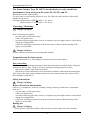
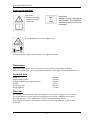
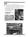
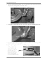
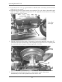
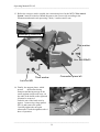
Front Sweeper FK 105
A08
FORM NO. 769-03278A
EN
MTD Products Aktiengesellschaft • Saarbrücken • Germany
Operating Manual FK 105
Table of Contents
Contents: ...................................................................................... Page
Unpacking / Mounting ...................................................................................... 3
For your safety .................................................................................................. 3
Use the machine properly.................................................................................. 4
Signs on the machine......................................................................................... 5
Maintenance ...................................................................................................... 5
Technical data ................................................................................................... 5
Warranty............................................................................................................ 5
Assembly ........................................................................................................... 6
Mounting ......................................................................................................... 10
Removal........................................................................................................... 12
Storage / Not in use ......................................................................................... 12
Operation ......................................................................................................... 13
Spare parts list ................................................................................................. 14
2
Operating Manual FK 105
The Front Sweeper Type FS 102/33 described below is only suitable for
attachment to lawn tractors in the series 48../49../50.. and 51...
Identification of the model number:
The type plate is located under the driver's seat. The fifth and sixth positions of the model
number are the series.
Example: Model number l3BW506N690 = 50.. Series
Model number 13AT491N684 = 49.. Series
Unpacking / Mounting
Danger of injury
Before mounting the machine
− stop the engine of the lawn tractor,
− remove the ignition key
− wait until all moving parts have come to a complete stop; the engine must be cooled down
− engage the parking brake
− remove the spark plug connectors on the lawn tractor so that accidental starting of the
engine is not possible.
Danger of burns
Let the exhaust cool down before mounting the machine.
Preparations on the lawn tractor
Remove attachments (e.g. front bumper) from the front of the lawn tractor.
For your safety
Observe safety and operating instructions. Read these instructions carefully before using the
machine for the first time. Observe all safety instructions during operation. Ensure
− that you are familiar with all the instructions,
− that all users of the machine have been informed of and have understood the instructions.
Also observe the safety and operating instructions in the manual for the lawn tractor which
these machine is attached to.
Safety instructions
Danger of injury
Before all work on this machine
(such as, e.g. attachment / removal, assembly, testing, checking, maintenance / adjustment
work etc.)
− stop the engine of the lawn tractor,
− remove the ignition key
− wait until all moving parts have come to a complete stop; the engine must be cooled down
− engage the parking brake
− remove the spark plug connectors on the lawn tractor so that accidental starting of the
engine is not possible.
During use
Danger of injury
− Keep persons, especially children, and pets away from the usage area of the machine.
3
Operating Manual FK 105
Use the machine properly
This machine is intended for use
− as a front sweeper for lawn tractors for sweeping domestic and leisure property
− according to the specifications and safety instructions contained in this operating manual.
Any other use shall be deemed to be improper use. The user is liable for all damage to third
parties and their property. Unauthorised modifications to the machine shall exclude any
liability of the manufacturer from any damage which may result.
Position information
For position information on the machine (e.g. left, right) we always assume as seen from the
driver's seat in the working direction of the machine.
Operation
The maximum speed of 6 km/h must not be exceeded.
Never carry out assembly, testing, checking, maintenance / adjustment work etc. while the
engine is running or hot.
If an object is struck or if the front sweeper starts to make unusual vibrations: stop the engine
immediately and examine the machine for damage. Contact a specialist repair shop in the case
of damage.
Before every use
Always check the front sweeper for any damage or wear.
The front sweeper must only be used when in perfect working order.
Check all controls, brackets and threaded connections for damage and firm seating. Replace
any damaged parts before operation.
The area to be swept must previously have been cleared of large objects. Stones, wire, pieces
of wood etc. can be ejected in an uncontrolled way from the sweeper under certain
circumstances.
4
Operating Manual FK 105
Signs on the machine
Important:
Read the operating
instructions before
starting up.
Important:
Danger of injury / damage to
the machine. The maximum
speed of 6 km/h must not be
exceeded.
Keep third parties out of the danger zone.
Always keep these signs on the machine in a legible condition.
Maintenance
Only allow maintenance work / repairs to be carried out by a specialist workshop.
Only use original spare parts or spare parts which have been approved by the manufacturer.
Technical data
Width:
Height without guide:
Length (without sweepings container):
Weight:
Sweeping width:
Brush diameter:
1000 mm
480 mm
880 mm
48.5 kg
1000 mm
330 mm
Warranty
The warranty conditions issued by our company or. the importer apply in every country.
We rectify defects on your machine according to the warranty conditions at no charge
provided the cause can be attributed to material or manufacturing defects.
In the case of a warranty claim, please contact your sales representative or the nearest
subsidiary.
5
Operating Manual FK 105
Mounting
Preparing the lawn tractor for mounting the front sweeper
1.
2.
For technical safety reasons, a cable bridge according to the instructions below must
be installed for the attachment of the sweeper. The installed cable bridge between
brake switch and seat safety switch ensures that the engine always automatically
switches off as soon as the operator leaves the driver's seat.
Open the engine cover and if necessary remove the right-hand side panel and / or the
fuel tank (depending on the design) in order to access the cable harness.
Open the black cable harness sheath
from the wiring harness to the ignition
switch (underneath the fuel tank) and
Fuel tank
expose the yellow cable.
removed
Electrical accessories:
A = vehicle cable 1.5 mm²
B = branch connector, blue
C = cable tie
3.
Connect cable "A" to the yellow cable with a branch connector "B"
A
B
6
Operating Manual FK 105
4.
Open the black cable harness sheath from the wiring harness to the brake switch (between
step and frame) and expose the yellow/white cable.
right
footboard
5. Connect the free end of cable "A" to the yellow/white cable with a branch connector "B".
A
B
6. Press all the cables back into the cable harness sheath and fasten the cable "A" in parallel
with the cable harness using 3 cable ties.
7. Replace right-hand side panel and/or fuel tank (depending on design).
8. It is necessary to limit
the lift-up height of the
mower deck due to the
additional V-belt pulley
under the engine. An
M12x25 bolt with 2
large washers and a lock
nut are mounted on the
lever connecting link for this.
7
Operating Manual FK 105
9. Lower the mower on to e.g. squared timber so that the strain relief clamp on the front side
of the deck is not stressed.
10. Unbolt the strain relief clamp from the cross member "D" on the front of the machine and
replace it with the supplied deck suspension "E". Re-adjust the tension distance according
to the original strain relief clamp.
D
View from
front right
E
11. Undo the fixing bolt of the engine V-belt pulley. Position the supplied V-belt pulley "F"
so that the pins on the spanner flats of the coupling nut act as drivers. Fix everything with
the whitworth bolt also supplied. Tightening torque 51-68 Nm.
F
12. Perform a test run and functional check - ensure that the engine always stops
automatically as soon as the operator leaves the driver's seat.
8
Operating
Manual FK 105
___________________________________________________________________________
13. Before the sweeper can be coupled, the connection pieces for the MTD "Fast Attach
System" must be bolted on. Match the parts to the correct side according to the
illustration and attach each part using 2 bolts, 2 washers and 2 nuts.
Sweeping machine
Thin washer
Hex. Bolt M8x25
Connection piece left
Thick washer
Lock nut M8
14. Finally, the support plates, which
protect
the brushes during
transport and during storage in the
carton against compressed areas, on
the ends of the brush on the right and
left must be removed.
Undo the nut of the brush axle by
approx. 3 turns using a ring spanner
SW 19 and remove the plates.
Carefully tighten the nut again
afterwards. Check the tightness after 1
hour of operation.
remove
plate
___________________________________________________________________________
9
Operating Manual FK 105
Attachment of the front sweeper
1.
Place the sweeper in position in front of the lawn tractor. Turn the locking element "G"
flat as shown in the picture. Hold the knob "H" with your left hand and the bracket "J"
with your right hand and lift the hook ends of the connecting plates onto the bolts of the
Fast-Attach-System "K".
H
J
G
K
2.
In the next step, you place the V-belt on the
extra pulley as shown in the picture.
(Put the mower deck in a low position)
Make sure that the V-belt runs round
the tension roller as illustrated.
10
Operating Manual FK 105
3.
Now swivel the locking elements "G" so that they engage in the holes of the side plates.
Go in front of the sweeper, hold the front edge of the brush deck and lift this until the
locking elements audibly engage in the tractor bore holes of the Fast-Attach-System.
The sweeper is coupled and the V-belt to the tractor has been correctly tensioned by the
spring-mounted tensioner.
G
V-belt
4.
Push the lifting tube "M" onto the lever of the sweeper on the right-hand side. A tube
hinged pin is used for locking. On the left-hand side, the extension tube "O" must be put
on the swivel rod "P" and locked with a spring cotter "Q". The angled handle end of the
tube should face upwards.
O (covered)
Q
P
M
N
11
Operating Manual FK 105
Removal of the front sweeper
1. Switch off the engine of the tractor. The sweeper is raised.
Wait until all parts are at a standstill. Let the exhaust area cool down or
use suitable work gloves.
Remove the lifting tube and the extension tube of the swivel rod from the sweeper.
In order to pull out the locking elements "G" of the Fast-Attach-System and to fold on to
the sides, hold the front edge of the brush deck and lift this at the same time.
Lower the sweeper on to the ground. The machine is now jack-knifed (photo). The V-belt
is not tensioned.
H
J
jack-knifed
2.
G
Set the mower deck in a low position and remove the V-belt from the additional pulley.
Let it simply lie underneath.
The same as for attachment, hold the sweeper again with the knob "H" and the bracket
"J" and lift it upward to the front out of the Fast-Attach-System.
Storage / Not in use
When not in use, the sweeper should be placed
vertically saving space on the brackets "R".
In this way, the brushes are not stressed and do
not acquire any flat places.
R
12
Operating Manual FK 105
Operation of the front sweeper
1. The sweeper is raised or lowered with the lifting tube "M".
For raising, the bar is simply moved up and down in relation to the step using the handle
until the sweeper completely engages in the "top position".
For lowering, the bar is lifted at the handle. After a slight resistance, the lowering occurs
slowly.
M
2.
For swivelling the brush deck, hold the handle of the extension tube of the swivel rod
"O", lift it upwards and move it forwards or backwards in order to swivel to the left or to
the right. The locking comb "S" locks the respective position when you release the bar.
Note: If you raise the sweeper slightly, the swivelling is very easy.
H
O
S
3.
The height adjustment of the brush is made using the knob "H". Undo the locking plate
by turning anticlockwise and adjust the height. The running brush should be pressed
approx. 15-20 mm on flat terrain.
13
Operating Manual FK 105
Tafel 1
Spare Parts List
MTD FK 105
16
1
25
27
24
23
22
13
21
26
2
15
16
20
19
29
8
14
7
8
9
5
6
28
18 17
30
16
22
10
12
33
31
39
49
4
3
30
11
32
54
55
38
41
40
34
29
37
35
35
47
56
36
42
44
45 44
43
52
48
46
14
51
50
52
53
Operating Manual FK 105
Spare Parts List
MTD FK 105
Pos. Artikel-Nr.
ohne
Abb.
Bezeichnung
4HM-Q06
Kehrbürstenwalze 33-10P
1
FKT-167
2
Tafel 1
Pos. Artikel-Nr.
(2x
=1m)
Bezeichnung
36
4HO-A08 Z1 6kt-Schraube M6x16
Bürstendeck MTD 100
37
4HW-B06 Z1
Scheibe, groß Ø 6
FKT-261
Bürstengetriebe MTD
38
4KC-B56
Führungsstift
3
4KB-S05
Schneckengetr. VF44
39
4HR-A08 Z1
Mutter M8
4
4HL-A02
Simmering 30
40
4HW-B08 Z1
Scheibe, groß Ø 8
5
FKT-164 Z
Halslager MTD
41
4HR-C08 Z1
Stopmutter M8
6
FKT-165
Bü-Welle MTD
42
4HR-I08 Z1
Käfigmutter M8
7
4HA-A20
Kugellager
43
4HO-C101 Z
6kt-Schraube M10x240
8
4HU-A20 1
Sicherungsring 20
44
4HW-B10 Z1
Scheibe, groß Ø 10
9
4HU-I42 1
Sicherungsring 42
45
4HR-C10 Z1
Stopmutter M10
10
4DS-C01
K-Stück 22
46
FKT-155 Z
Stützöse M1
11
4DM-B15 Z
Distanzrohr
47
4AZ-122
Schwenkrohr
12
4KH-P04
Paßfeder
48
4HJ-G02
Griffhülle 15
13
4HU-A50 1
Sicherungsring 50
49
4KC-F01
Federstecker A
14
4HO-A34 Z1
6kt-Schraube M12x30
50
4AZ-128
Stützspindel M1
15
4HW-D12 Z1 Scheibe, dick Ø12
51
4DA-I01 Z
Konterlasche
16
4HR-C12 Z1
Stopmutter M12
52
4HW-A10 Z1
Scheibe Ø 10
17
4HO-A07 Z1
6kt-Schraube M6x12
53
4HJ-B07
Knauf
18
4HW-F06 Z1 Federring M6
54
4HB-A41
Keilriemen, oben
19
4AZ-A13 Z
Keilriemenscheibe 118
55
FKT-258
K-Abdeckung
20
4HX-H36 1
Spannhülse 8x36
56
4HO-S47 Z
Bordwandschr. M8x15
21
4HO-A61 Z
6kt-Schraube M12x65
22
4HW-B12 Z1
Scheibe, groß Ø 12
23
4HR-A12 Z1
Mutter M12
24
4HW-A12 Z1
Scheibe, Ø 12
25
4HJ-D02 1
Kunststoff-Scheibe
26
FKT-259
Schwenkstütze M1 kpl.
27
4HK-S01
Silentblock
28
4HO-A09 Z1
6kt-Schraube M6x20
29
4HR-C06 Z1
Stopmutter M6
30
4AZ-107 Z
Bürstenmitnehmer 44
Endet eine Art.-Nr. mit
31
4DC-B01
Mitnehmerstab
einer angehängten "1",
32
4AZ-129 Z
Bürstenachse 1m
so ist die VE = 10 St.
33
4DA-E03 Z
Scheibe
34
FKT-151
Bürstenträger M1
35
4DA-C91 Z
K-Führung MD
(6004 2RS)
15
Operating Manual FK 105
Spare Parts List
MTD FK 105
64
63
66
Tafel 2
66
67
64
63
65
65
62
61
69
68
70
72
92
74
70
71
71
81
79
80
76
67
73
84
71
70
91
78
75
83
72
85
86
88
90
77
82
87
79
88
89
67
79
101
102
103
105
108
84 85
93
94
104
97
99
109
98
84
106
111
110
107
100
16
96
95
Operating Manual FK 105
Spare Parts List
MTD FK 105
Pos. Artikel-Nr.
Bezeichnung
Pos. Artikel-Nr.
Tafel 2
Bezeichnung
61
4DA-G27 Z
Kupplungsblech MTD li.
97
FTS-179 Z
Zugbügel M500
62
4DA-G26 Z
Kupplungsblech MTD re.
98
4HW-B12 Z1
Scheibe, groß Ø 12
63
4DC-F60 Z
Riegel MD
99
4HR-A12 Z1
Mutter M12
64
4HI-B07 Z
Druckfeder MD
100
4HR-C12 Z1
Stopmutter M12
65
4HX-E22
Spannhülse 4x22
101
4DC-C20 Z
Zugstange M1
66
4DA-I07 Z
Ü-Lasche
102
4HI-B01
Druckfeder 17/54
67
4HW-A20 Z1 Scheibe Ø 21
103
4DC-J12 Z
Federdruckstück M1
68
4DA-C90 Z
104
4HR-C06 Z1
Stopmutter M6
69
4HW-B08 Z1 Scheibe, groß Ø 8
105
FKT-253
Spanner M1 kpl.
70
4HO-A14 Z1
106
4AZ-205
Spannrolle B2
71
4HW-A08 Z1 Scheibe Ø 8
107
FKT-153 Z
Spannerarm M1
72
4HA-Y20
Y-Lager 20
108
4HO-C31 Z1
6kt-Schraube M10x60
73
FKT-150
Wellengehäuse M1
109
4HO-M53 Z
Zoll-Schraube UNF175
74
4HO-A15 Z1
6kt-Schraube M8x25
110
4HW-F10 Z1
Federring M 10
75
4HW-D08 Z1 Scheibe, dick Ø 8
111
4HR-A51 Z1
Zollmutter 3/8" UNF
76
4HR-C08 Z1
Stopmutter M8
77
4DC-H55
V-Welle M1
78
4AZ-A07 Z
Keilriemenscheibe 80
79
4HX-H36 1
Spannhülse 8x36
80
4KC-A03 Z
Stellring 20
81
4HO-A06 Z1
6kt-Schraube M6x10
82
4DA-H06 Z
Lagerplatte
83
4HO-A23 Z1
6kt-Schraube M10x20
84
4HW-A10 Z1
Scheibe, Ø 10
85
4HR-C10 Z1
Stopmutter M10
86
4DB-D02 Z
Lasche
87
4DC-F17 Z
Bolzen
88
4KC-A15
Federscheibe 12
89
FKT-152 Z
Ausheber M1
90
4AZ-802
Rohrklappsplint 6/32
91
FKT-260
Heberohr M1
Endet eine Art.-Nr. mit
92
4HJ-G03
Handgriff
einer angehängten "1",
93
4AZ-A30 Z
Keilriemenscheibe 100
so ist die VE = 10 St.
94
4HB-X32 S
Keilriemen, unten
95
4AZ-A68 Z
Motor-K-Scheibe M1
96
4HO-M57
Zoll-Schraube UNF 65
Stützschutz MD
6kt-Schraube M8x20
17