1
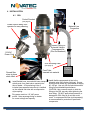
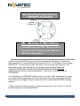
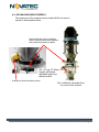
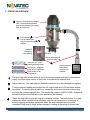
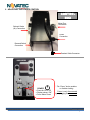
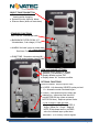
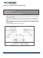
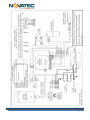
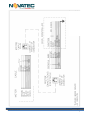
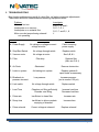
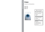
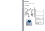
VACUUM LOADERS GSL Series Models: GSL-19 & GSL-19-MM (Patent Pending) GSL-19 Tilted GSL-19 GSL-19-MM Machine Mount Instruction Manual GSL 9-12-12 IM Doc. GSL IM 8-21-12 Page 1 NOTES: Please record the following information, which is specific to this piece of equipment, in the space provided. Our Parts/Service Department will need these numbers to properly respond to any of your requests. Instruction Manual: GSL 9-12-12 IM Model #:___________________________ Serial #____________________________ DISCLAIMER: NOVATEC, Inc. shall not be liable for errors contained in this Instruction Manual nor for misinterpretation of information contained herein. NOVATEC shall not, in any event, be held liable for any special, indirect or consequential damages in connection with performance or use of this information. GSL 9-12-12 IM Page 2 Table of Contents 1 SPECIFICATIONS ................................................................................................................. 4 1.1 Options: ............................................................................................................................... 4 2 PRINCIPLE OF OPERATION ................................................................................................ 4 3 UNPACKING AND INSPECTION .......................................................................................... 5 4 INSTALLATION...................................................................................................................... 6 4.1 GSL ..................................................................................................................................... 6 4.2 GSL MACHINE MOUNT MODELS ........................................................................................ 8 5 OPERATION OVERVIEW ...................................................................................................... 9 6 ADJUSTING THE LOADER CONTROL .............................................................................. 10 7 INITIAL STARTUP ............................................................................................................... 12 8 ELECTRICAL CONNECTIONS FOR LOADER OPTIONS .................................................. 13 9 TROUBLESHOOTING ......................................................................................................... 16 10 WARRANTY – NOVATEC, INC. - Effective Date 6-12-12 ................................................... 17 FOREWORD This manual is dedicated to the principle that any engineered system will have many elements contributing to the smooth operation of the system, and that these must be understood in order that installation and operation can proceed successfully. The electrical and mechanical components in the GSL Series loaders have been manufactured, selected and assembled with care to give you excellent service. All components of your GSL loader have been carefully engineered and manufactured and have been thoroughly inspected for quality, function and performance. Before installing this system, please read this manual, review the diagrams and the safety information. This should save valuable installation and operation time later and will help ensure safe operation and long life. GSL 9-12-12 IM Page 3 1 SPECIFICATIONS NOVATEC GSL Series vacuum loaders are completely automatic self-cleaning vacuum loaders designed to convey virgin pellets and regrind materials from storage containers to drying hoppers or directly to process machines. Each unit is shipped complete with all controls for immediate operation, and include a hardware package. The hardware package includes 15 feet of flexible vacuum hose, hose clamps and a material pick up lance, plus a 12’ extension cable for remote mounting the standard Control Pendant. The GSL-19 is designed for mounting on drying hoppers. The GSL-19-MM is designed for mounting on a process machine and is supplied with 8 lb. capacity sight glass with a height adjustable photo-eye demand switch. 1.1 Options: Additional tubing and fittings (Rigid tubing, elbows, bolted couplers, etc.) External Proportioning Valve Purge Valve Proximity Switch, Capacitance Type Spare 12’ control pendant 2 PRINCIPLE OF OPERATION A Load Cycle begins with a compressed air blowback pulse to clear any isolated material particles or dust buildup that may remain on the flapper discharge valve. This action ensures a tight vacuum seal for each Load Cycle. The loader then activates our powerful, maintenance free, brushless motor to create a vacuum, which draws material into a chamber. After the load time setting has expired, the vacuum motor is turned off and the negative pressure in the chamber is relieved. Material in the chamber then falls through the bottom, past the flapper while compressed air is pulsed through the filter to dislodge any contaminants or fines that may have accumulated. This cycle is repeated as many times as necessary, until the unit is shut off by the rise of the conveyed material in the area below the loader which trips the level switch, removing the ‘demand’ signal. Machine mounted units do not have a flapper valve or mercury switch, but instead utilize a clear sight tube, which mounts directly to the machine throat, with a sensor to control loader operation based upon the level of material within the sight tube. The sensor may be either a capacitance style, with sensitivity adjustment, or a pair of photoelectric sensors, an emitter and a receiver. The bottom flange of a Machine Mount unit is normally supplied undrilled to allow the customer to drill the appropriate mounting pattern for a particular process machine. GSL 9-12-12 IM Page 4 3 UNPACKING AND INSPECTION NOVATEC Vacuum loaders are shipped complete, with all controls for automatic operation. The only utilities required are a 115 VAC power supply and clean, dry compressed air at approximately 80 PSI. After receipt of the unit, completely inspect it for damage. Although the units are packaged securely, vibration and mishandling during transit can cause damage. Please report any damage to your carrier promptly. GSL 9-12-12 IM Page 5 4 INSTALLATION 4.1 GSL Control Pendant (see page 6) 1 Locate HINGE away from operator for easy cleaning Material Line Connection 1 3 Connect Fitting on Solenoid Valve to Compressed Air (Pilot for Blowback) 2 115 VAC Power Cord GSL Mounting Plate (see page 3) Domed filter stays in place when tilted. 1 2 Feed Tube Inserted into material Install flexible hose, secured with hose clamps at both ends, from feed tube to material inlet tube of loader. A Proportioning Valve, if included (see separate instructions) is installed on the material inlet tube with a compression style coupling. Plug power cord into 115 VAC power source. Note amperage listing on loader for correct voltage and capacity. GSL 9-12-12 IM 3 Plastic Pellets Install flexible compressed air line to the solenoid valve fitting (below lid hinge). Source should provide clean, dry compressed air supply 80 -100 psi. Use only full-flow quick disconnect fitting for best blowback performance. CAUTION: Use a second wrench to hold the fitting on the GSL securely while tightening the hose fitting. DO NOT apply direct pressure, or damage the GSL fitting or an air leak could result. A compressed air filter (sold separately) is recommended for protection of pneumatic components. Page 6 GSL Mounting Flange Patterns – NOVATEC Compatible GSL – Mounting to Other Patterns Compatible with NOVATEC / Maguire GVL-10 Compatible with Conair AL2, AL5, DB8 and DB12 mounting patterns New or existing NOVATEC hoppers will allow mounting the GSL directly. Hoppers with large openings for 5” dump throat models will use the VL-12 to VL-38 adaptor, included with the GSL unit. You may bolt the loader base plate on the receiving hopper securely, and then install the GSL cast cone with the front hinge pin and rear flange locking tab. CAUTION: FASTEN GSL FLANGE TO RIGID MOUNTING SURFACE BEFORE OPERATING OR TILTING THE HOPPER BODY. USE ONLY LOCKING, CAPTIVE FASTENERS. For mounting to non-NOVATEC hoppers, note your model of GSL and prepare the hopper to be loaded with the appropriate cut-out and bolt pattern according to the diagrams above. These have been designed to allow for direct mount into several non-NOVATEC mounting patterns. Secure fasteners should be employed, fastened permanently to the hopper lid to prevent possible dropping into the hopper/material. GSL 9-12-12 IM Page 7 4.2 GSL MACHINE MOUNT MODELS The upper part of the machine mount model still tilts for ease of access to clean/replace filters. Upper and lower parts of machine mount model are connected together with a plate that slides into place. 8 lb. (3.6 kg) JIT Glass Hopper with heightadjustable photo eye demand switch A detent pin locks the plate in place. GSL-12-MM with adjustable Photo Eye Level Sensor installed GSL 9-12-12 IM Page 8 5 OPERATION OVERVIEW 3 Vacuum motor should fill loader until 5 seconds before pellets stop moving through the convey hose and no more. 2 Press button to turn on loader and adjust load time with + buttons. Rotate to change air inlet opening 1 Air inlet Adjust conveying air with feed tube ring Too much air…slow loading and hose wear morelittle likely Too air…plugged material line is possible Good mixture of air and material 4 Assure that the feed tube is inserted into material Plastic Pellets 1 The feed tube joins air with material and it should be plunged (and kept) in the material supply, but allow upper section of feed tube to remain above material level. 2 Adjust load time. See next page for detailed instructions on control settings and options. 3 4 To allow optimum loading and longest filter life, adjust load time to fill the loader without over filling. To identify optimal load time, operate the motor until material stops moving and note the corresponding fill time. This means the loader is OVER FILLED. Subtract 5 seconds from the over-filled time to limit premature filter blinding. Rotate the feed tube ring for the best air to material mixture. The best mixture of air and material will allow material to flow efficiently, with the right proportion of conveying air, without clogging and without rapid hose wear. Be sure material flows into loader consistently from start to finish, without surging or floating at the pickup or loader inlet. GSL 9-12-12 IM Page 9 6 ADJUSTING THE LOADER CONTROL CONTROL BOX Motor Plug Connection Solenoid Valve (Air) Connection Power Connection Demand Switch Connection Pendant Cable Connector POWER* Press for On or Off Display shows “ON” Force Alarm Reset GSL 9-12-12 IM * The “Power” button enables or disables loading. Power is only disconnected by unplugging the power cord. Page 10 SELECT FUNCTION BUTTON ● Button selects functions for viewing and/or changing. ● Selected function lights up, below. ● Silences Alarm (does not reset alarm) STANDARD FUNCTIONS ● MOTOR ON: Seconds per load ● BLOWBACK FILTER CLEAN: “XY” X=loads/clean; Y=air charge (Y*0.4s) ● ALARM: ‘No Load’ cycles to create alarm “0” = Alarm disabled. See Alarm Function description (p.7) ● DUMP TIME: Seconds or minutes (M) (Forced pause between Load Cycles) VIEW and CHANGE SETTINGS ● Selected setting appears in window ● Increase (+) or decrease (-) values ● Display defaults to show “ON” ● Display shows “AL” for alarm condition OPTIONAL FUNCTIONS PROPORTIONING: Requires optional Valve. ● LAYERS: # of alternating VIR/REG cycles per load. ‘A’ = Automatic control calculated Layers. ● PURGE: Uses specified time to empty the material line. Inserted as final interval of total MOTOR ON time (does not extend MOTOR ON time). Requires optional Valve. TOTAL CONVEY TIME per Load Regrind = (Motor On – Purge) * REG % Virgin = (Motor On – Purge – Regrind) NOTE: Divide these times by LAYERS value for individual layer cycles times. REGRIND: % of Convey Time for regrind ______________________________________ GSL 9-12-12 IM Page 11 7 INITIAL STARTUP NO LOAD ALARM FUNCTION ENABLING: When the GSL is turned ON, the control operates to fill the ‘hopper’ being loaded. To avoid nuisance alarms, the NO LOAD ALARM is not enabled until the demand has been satisfied as follows: The 'demand' input remains off for the ‘Demand Timer’ (Dump Time plus ~5 seconds). The control assumes this timing sequence indicates the ‘hopper’ has completed an initial fill process. NORMAL OPERATION: After the NO LOAD ALARM is enabled as described, a counter will increment each time the Demand Sensor Input reappears before the Demand Timer expires after a Load Cycle. The counter is cleared when the Demand Input does not re-appear before the demand timer expires. NO LOAD ALARM occurs when the counter reaches the user selected Alarm Set Point value. The Loader continues load attempts after the ‘Alarm’ Output is energized. If 8 cycles pass without the alarm counter being cleared, the Loader will shut down. CLEARNING AN ALARM CONDITION: Pressing the ‘Select Button’ will silence the 'alarm' output. The alarm counter will continue. The alarm clears if the Demand Input stays off for the full Demand Timer (ie: the full is hopper). After Alarm Shutdown, cycle the Loader OFF, then ON, to clear the alarm and restart operation. GSL 9-12-12 IM Page 12 8 ELECTRICAL CONNECTIONS FOR LOADER OPTIONS -Proportioning Valve -Purge Valve -Output to Auxiliary Alarm Device 1. Remove the loader control enclosure, and carefully tip the enclosure out without straining wires connected to the control. 2. Locate the correct terminals for the device you are connecting, as shown in the diagrams that follow, and connect the wires carefully. Use care as some terminals accommodate multiple wires. 3. Route the cable out of the control box, through one of the slots in the side. Tightly install a tie wrap (not included) onto the cable, inside the control enclosure to prevent the cable from being pulled out of the box. 4. Tip control box back into place and tighten top screw. GSL 9-12-12 IM Page 13 GSL 9-12-12 IM Page 14 GSL 9-12-12 IM Page 15 9 TROUBLESHOOTING Most loader problems are a result of a dirty filter, air leaks or improper adjustments. These items should be checked before assuming equipment failure. Problem Motor will not run Inadequate or no vacuum Inadequate or no material flow Motor runs but proportioning solenoid not operating CHECK A. Power Supply Investigate A, B, C, H, and L D, E, F, G, J D, E, F, and G, I, K L CONDITIONS No voltage or voltage incorrect voltage at outlet B. Stop/Start Switch No voltage through switch C. Vacuum motor No voltage at motor D. Filter E. Air Ducts F. Leaks in system G. Blowback air pressure incorrect SOLUTION Check incoming power supply Replace switch See A,B, & L Filter dirty Replace filter (Also see G & J) Obstructed Remove obstruction Air leaking into system Low pressure Replace gaskets & repair leaks as necessary Increase pressure (not to exceed 125 psi) H. Limit switch No voltage through switch Replace switch I. Load Time Chamber not filling sufficiently Chamber over-filling Increase load time Decrease load time J. Pulse rate Insufficient to clean filter Increase rate K. Dump time Insufficient to allow complete emptying of chamber Increase time L. Pulse solenoid Correct voltage at solenoid GSL 9-12-12 IM Replace solenoid Page 16 10 WARRANTY – NOVATEC, INC. - Effective Date 6-12-12 NOVATEC, INC. offers COMPREHENSIVE PRODUCT WARRANTIES on all of our plastics auxiliary equipment. We warrant each NOVATEC manufactured product to be free from defects in materials and workmanship, under normal use and service for the periods listed under “Warranty Periods”. The obligation of NOVATEC, under this warranty, is limited to repairing or furnishing, without charge, a similar part to replace any part which fails under normal use due to a material or workmanship defect, within its respective warranty period. It is the purchaser’s responsibility to provide NOVATEC with immediate written notice of any such suspected defect. Warranted replacement parts are billed and shipped freight pre-paid. The purchaser must return the suspect defective part, freight prepaid and with identifying documentation to receive full credit for the part returned. NOVATEC shall not be held liable for damages or delay caused by defects. No allowance will be made for repairs or alterations without the written consent or approval of NOVATEC. The provisions in equipment specifications are descriptive, unless expressly stated as warranties. The liability of NOVATEC to the purchaser, except as to title, arising out of the supplying of the said equipment, or its use, whether based upon warranty, contract or negligence, shall not in any case exceed the cost of correcting defects in the equipment as herein provided. All such liability shall terminate upon the expiration of said warranty periods. NOVATEC shall not in any event be held liable for any special, indirect or consequential damages. Commodities not manufactured by NOVATEC are warranted and guaranteed to Novatec by the original manufacturer and then only to the extent that NOVATEC is able to enforce such warranty or guaranty. NOVATEC, Inc. has not authorized anyone to make any warranty or representation other than the warranty contained here. Non-payment of invoice beyond 90 days will invalidate the warranty. A renewed warranty can be purchased directly from Novatec. Please note that we always strive to satisfy our customers in whatever manner is deemed most expedient to overcome any issues in connection with our equipment. Warranty Periods: Note: All warranty periods commence with the shipment of the equipment to the customer. 5-Years GSL Vacuum Loader (No Exclusions) This warranty shall not apply to equipment: 1. 2. 3. Repaired or altered without written approval of NOVATEC unless such repair or alteration was, in our judgment, not responsible for the failure Which has been subject to misuse, negligence, accident or incorrect wiring by others Warranty is void if processing rates exceed manufacturer-recommended levels or if damage is caused by ineffective power isolation and/or power spikes/sags or incorrect installation. NOTE: All conditions and content of this warranty are subject to changes without notice. GSL 9-12-12 IM Page 17