1
Forms Printer 248x/249x
Technical Reference
October 2000
www.lexmark.com
Third Edition (October 2000)
The following paragraph does not apply to the United Kingdom or any country
where such provisions are inconsistent with local law: LEXMARK INTERNATIONAL, INC. PROVIDES THIS PUBLICATION “AS IS” WITHOUT WARRANTY OF ANY KIND, EITHER EXPRESS OR IMPLIED, INCLUDING, BUT
NOT LIMITED TO, THE IMPLIED WARRANTIES OF MERCHANTABILITY OR
FITNESS FOR A PARTICULAR PURPOSE. Some states do not allow disclaimer of
express or implied warranties in certain transactions, therefore, this statement
may not apply to you.
This publication could include technical inaccuracies or typographical errors.
Changes are periodically made to the information herein; these changes will be
incorporated in later editions of the publication. Improvements and/or changes
in the product(s) and/or the program(s) described in this publication may be
made at any time.
Publications are not stocked at the address given below; requests for publications
should be made to your point of purchase.
A form for reader's comments is provided at the back of this publication. If the
form has been removed, comments may be addressed to Lexmark International,
Inc., Department F95/035-3, 740 New Circle Road N.W., Lexington, Kentucky
40511-1876, U.S.A. Lexmark may use or distribute any of the information you supply in any way it believes appropriate without incurring any obligation to you.
Lexmark is a trademark of Lexmark International, Inc.
Other trademarks are the property of their respective owners.
© Copyright Lexmark International, Inc. 1993, 2000.
All rights reserved.
UNITED STATES GOVERNMENT RESTRICTED RIGHTS
This software and documentation are provided with RESTRICTED RIGHTS. Use,
duplication or disclosure by the Government is subject to restrictions as set forth
in subparagraph (c)(1)(ii) of the Rights in Technical Data and Computer Software
clause at DFARS 252.227-7013 and in applicable FAR provisions: Lexmark International, Inc., Greenwich, CT 06836.
Contents
Section 1 - Introduction . . . . . . . . . . . . . . . . . . . . . . . . 9
Available Options . . . . . . . . . . . . . . . . . . . . . . . . . . . . . . . . . . . . . . . . . . . . . . . . . . . . . . . . 10
Physical Characteristics . . . . . . . . . . . . . . . . . . . . . . . . . . . . . . . . . . . . . . . . . . . . . . . . . . . 10
Print Speeds . . . . . . . . . . . . . . . . . . . . . . . . . . . . . . . . . . . . . . . . . . . . . . . . . . . . . . . . . . . . 11
Printhead Description . . . . . . . . . . . . . . . . . . . . . . . . . . . . . . . . . . . . . . . . . . . . . . . . . . . . . 11
248x . . . . . . . . . . . . . . . . . . . . . . . . . . . . . . . . . . . . . . . . . . . . . . . . . . . . . . . . . . . . . . 11
249x . . . . . . . . . . . . . . . . . . . . . . . . . . . . . . . . . . . . . . . . . . . . . . . . . . . . . . . . . . . . . . 11
Printhead Movement . . . . . . . . . . . . . . . . . . . . . . . . . . . . . . . . . . . . . . . . . . . . . . . . . 12
Environmental Conditions . . . . . . . . . . . . . . . . . . . . . . . . . . . . . . . . . . . . . . . . . . . . . . . . . 12
Optimum Temperature Ranges . . . . . . . . . . . . . . . . . . . . . . . . . . . . . . . . . . . . . . . . . 12
Vibration . . . . . . . . . . . . . . . . . . . . . . . . . . . . . . . . . . . . . . . . . . . . . . . . . . . . . . . . . . 12
Clearances . . . . . . . . . . . . . . . . . . . . . . . . . . . . . . . . . . . . . . . . . . . . . . . . . . . . . . . . . 12
Power Requirements . . . . . . . . . . . . . . . . . . . . . . . . . . . . . . . . . . . . . . . . . . . . . . . . . . . . . 12
Power Consumption . . . . . . . . . . . . . . . . . . . . . . . . . . . . . . . . . . . . . . . . . . . . . . . . . 12
Alternating Current Line Voltage Power. . . . . . . . . . . . . . . . . . . . . . . . . . . . . . . . . . 13
Power Cord . . . . . . . . . . . . . . . . . . . . . . . . . . . . . . . . . . . . . . . . . . . . . . . . . . . . . . . . 13
Noise Emission Value . . . . . . . . . . . . . . . . . . . . . . . . . . . . . . . . . . . . . . . . . . . . . . . . . . . . 13
Paper Specifications . . . . . . . . . . . . . . . . . . . . . . . . . . . . . . . . . . . . . . . . . . . . . . . . . . . . . . 14
2480/2490 (Narrow Carriage Models). . . . . . . . . . . . . . . . . . . . . . . . . . . . . . . . . . . . 14
2481/2491 (Wide Carriage Models) . . . . . . . . . . . . . . . . . . . . . . . . . . . . . . . . . . . . . 15
Ribbon Specifications . . . . . . . . . . . . . . . . . . . . . . . . . . . . . . . . . . . . . . . . . . . . . . . . . . . . 17
Diagnostics . . . . . . . . . . . . . . . . . . . . . . . . . . . . . . . . . . . . . . . . . . . . . . . . . . . . . . . . . . . . . 17
Power-On Diagnostics . . . . . . . . . . . . . . . . . . . . . . . . . . . . . . . . . . . . . . . . . . . . . . . 17
Printer Test. . . . . . . . . . . . . . . . . . . . . . . . . . . . . . . . . . . . . . . . . . . . . . . . . . . . . . . . . 18
Programming Examples . . . . . . . . . . . . . . . . . . . . . . . . . . . . . . . . . . . . . . . . . . . . . . . . . . . 18
Section 2 - Set Initial Conditions (SIC) Command . . 21
SIC Command Format . . . . . . . . . . . . . . . . . . . . . . . . . . . . . . . . . . . . . . . . . . . . . . . . . . . . 21
Section 3 - IBM Emulation Mode Printer Commands 27
Control Codes . . . . . . . . . . . . . . . . . . . . . . . . . . . . . . . . . . . . . . . . . . . . . . . . . . . . . . . . . . . 27
Escape Sequences . . . . . . . . . . . . . . . . . . . . . . . . . . . . . . . . . . . . . . . . . . . . . . . . . . . . . . . . 28
Printer Command Parameters . . . . . . . . . . . . . . . . . . . . . . . . . . . . . . . . . . . . . . . . . . . . . . . 28
Command Structure . . . . . . . . . . . . . . . . . . . . . . . . . . . . . . . . . . . . . . . . . . . . . . . . . . . . . . 29
Example of IBM Emulation Mode Printer Command. . . . . . . . . . . . . . . . . . . . . . . . 30
Printer Command Quick Reference (IBM Emulation Mode) . . . . . . . . . . . . . . . . . . . . . . 31
Selecting a Character Set . . . . . . . . . . . . . . . . . . . . . . . . . . . . . . . . . . . . . . . . . . . . . . . . . . 33
Select Character Set 1 . . . . . . . . . . . . . . . . . . . . . . . . . . . . . . . . . . . . . . . . . . . . . . . . 33
iii
Select Character Set 2 . . . . . . . . . . . . . . . . . . . . . . . . . . . . . . . . . . . . . . . . . . . . . . . . 33
Select Code Page . . . . . . . . . . . . . . . . . . . . . . . . . . . . . . . . . . . . . . . . . . . . . . . . . . . . . . . . 33
Print From Code Page . . . . . . . . . . . . . . . . . . . . . . . . . . . . . . . . . . . . . . . . . . . . . . . . . . . . 34
Continuously Print Characters from a Code Page . . . . . . . . . . . . . . . . . . . . . . . . . . . 34
Print One Character . . . . . . . . . . . . . . . . . . . . . . . . . . . . . . . . . . . . . . . . . . . . . . . . . . 35
Download a Character Set . . . . . . . . . . . . . . . . . . . . . . . . . . . . . . . . . . . . . . . . . . . . . . . . . 35
Select Global Font . . . . . . . . . . . . . . . . . . . . . . . . . . . . . . . . . . . . . . . . . . . . . . . . . . . . . . . 36
Select 12 cpi. . . . . . . . . . . . . . . . . . . . . . . . . . . . . . . . . . . . . . . . . . . . . . . . . . . . . . . . 40
Select Print Mode . . . . . . . . . . . . . . . . . . . . . . . . . . . . . . . . . . . . . . . . . . . . . . . . . . . 40
Select Print Type Style . . . . . . . . . . . . . . . . . . . . . . . . . . . . . . . . . . . . . . . . . . . . . . . . . . . . 42
Emphasized (Bold) Print . . . . . . . . . . . . . . . . . . . . . . . . . . . . . . . . . . . . . . . . . . . . . . 44
Double-Strike Print . . . . . . . . . . . . . . . . . . . . . . . . . . . . . . . . . . . . . . . . . . . . . . . . . . 44
Superscript or Subscript. . . . . . . . . . . . . . . . . . . . . . . . . . . . . . . . . . . . . . . . . . . . . . . 45
Set Print Direction . . . . . . . . . . . . . . . . . . . . . . . . . . . . . . . . . . . . . . . . . . . . . . . . . . . 45
Continuous Double-wide Printing . . . . . . . . . . . . . . . . . . . . . . . . . . . . . . . . . . . . . . . 46
Score Select . . . . . . . . . . . . . . . . . . . . . . . . . . . . . . . . . . . . . . . . . . . . . . . . . . . . . . . . 46
Continuous Underline . . . . . . . . . . . . . . . . . . . . . . . . . . . . . . . . . . . . . . . . . . . . . . . . 47
Continuous Overscore . . . . . . . . . . . . . . . . . . . . . . . . . . . . . . . . . . . . . . . . . . . . . . . . 47
Set Print Quality . . . . . . . . . . . . . . . . . . . . . . . . . . . . . . . . . . . . . . . . . . . . . . . . . . . . . . . . . 48
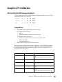
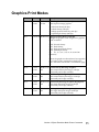
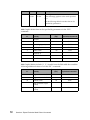
Graphics Print Modes . . . . . . . . . . . . . . . . . . . . . . . . . . . . . . . . . . . . . . . . . . . . . . . . . . . . . 49
Normal Density Bit Image Graphics . . . . . . . . . . . . . . . . . . . . . . . . . . . . . . . . . . . . . 49
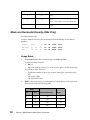
Mode and Horizontal Density (249x Only) . . . . . . . . . . . . . . . . . . . . . . . . . . . . . . . . 50
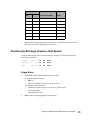
Dual-Density Bit Image Graphics (Half Speed) . . . . . . . . . . . . . . . . . . . . . . . . . . . . 51
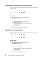
Dual-Density Bit Image Graphics (Normal Speed). . . . . . . . . . . . . . . . . . . . . . . . . . 52
High-Density Bit Image Graphics . . . . . . . . . . . . . . . . . . . . . . . . . . . . . . . . . . . . . . . 52
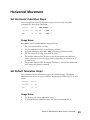
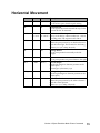
Horizontal Movement . . . . . . . . . . . . . . . . . . . . . . . . . . . . . . . . . . . . . . . . . . . . . . . . . . . . 53
Set Horizontal Tabulation Stops . . . . . . . . . . . . . . . . . . . . . . . . . . . . . . . . . . . . . . . . 53
Set Default Tabulation Stops . . . . . . . . . . . . . . . . . . . . . . . . . . . . . . . . . . . . . . . . . . . 53
Set Horizontal Margins . . . . . . . . . . . . . . . . . . . . . . . . . . . . . . . . . . . . . . . . . . . . . . . 54
Move Current Print Position . . . . . . . . . . . . . . . . . . . . . . . . . . . . . . . . . . . . . . . . . . . 54
Line Control . . . . . . . . . . . . . . . . . . . . . . . . . . . . . . . . . . . . . . . . . . . . . . . . . . . . . . . . . . . . 55
Automatic Line Feed (LF) . . . . . . . . . . . . . . . . . . . . . . . . . . . . . . . . . . . . . . . . . . . . . 55
Reverse Line Feed . . . . . . . . . . . . . . . . . . . . . . . . . . . . . . . . . . . . . . . . . . . . . . . . . . 55
Move Paper Vertically. . . . . . . . . . . . . . . . . . . . . . . . . . . . . . . . . . . . . . . . . . . . . . . . 55
Set Vertical Units. . . . . . . . . . . . . . . . . . . . . . . . . . . . . . . . . . . . . . . . . . . . . . . . . . . . 56
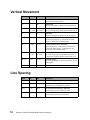
Vertical Tabulation . . . . . . . . . . . . . . . . . . . . . . . . . . . . . . . . . . . . . . . . . . . . . . . . . . . . . . . 56
Set Vertical Tabulation Stops . . . . . . . . . . . . . . . . . . . . . . . . . . . . . . . . . . . . . . . . . . 56
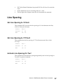
Line Spacing . . . . . . . . . . . . . . . . . . . . . . . . . . . . . . . . . . . . . . . . . . . . . . . . . . . . . . . . . . . . 57
Set Line Spacing to 1/8 Inch . . . . . . . . . . . . . . . . . . . . . . . . . . . . . . . . . . . . . . . . . . . 57
Set Line Spacing to 7/72 Inch . . . . . . . . . . . . . . . . . . . . . . . . . . . . . . . . . . . . . . . . . . 57
Activate Line Spacing for Text . . . . . . . . . . . . . . . . . . . . . . . . . . . . . . . . . . . . . . . . . 57
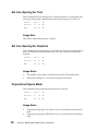
Set Line Spacing for Text . . . . . . . . . . . . . . . . . . . . . . . . . . . . . . . . . . . . . . . . . . . . . 58
Set Line Spacing for Graphics. . . . . . . . . . . . . . . . . . . . . . . . . . . . . . . . . . . . . . . . . . 58
Porportional Space Mode . . . . . . . . . . . . . . . . . . . . . . . . . . . . . . . . . . . . . . . . . . . . . 58
Set Top of Form and Page Length . . . . . . . . . . . . . . . . . . . . . . . . . . . . . . . . . . . . . . . . . . . 59
Set Top of Form. . . . . . . . . . . . . . . . . . . . . . . . . . . . . . . . . . . . . . . . . . . . . . . . . . . . . 59
iv
Set Page Length in Inches . . . . . . . . . . . . . . . . . . . . . . . . . . . . . . . . . . . . . . . . . . . . . 59
Set Page Length in Lines . . . . . . . . . . . . . . . . . . . . . . . . . . . . . . . . . . . . . . . . . . . . . . 59
Set Skip Perforation. . . . . . . . . . . . . . . . . . . . . . . . . . . . . . . . . . . . . . . . . . . . . . . . . . 60
Cancel Skip Perforation. . . . . . . . . . . . . . . . . . . . . . . . . . . . . . . . . . . . . . . . . . . . . . . 60
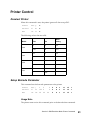
Printer Control . . . . . . . . . . . . . . . . . . . . . . . . . . . . . . . . . . . . . . . . . . . . . . . . . . . . . . . . . . 61
Deselect Printer . . . . . . . . . . . . . . . . . . . . . . . . . . . . . . . . . . . . . . . . . . . . . . . . . . . . . 61
Setup Barcode Parameter. . . . . . . . . . . . . . . . . . . . . . . . . . . . . . . . . . . . . . . . . . . . . . 61
Setup Barcode Data . . . . . . . . . . . . . . . . . . . . . . . . . . . . . . . . . . . . . . . . . . . . . . . . . . 63
Section 4 - Epson Mode Printer Commands . . . . . . 65
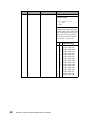
Font Selection . . . . . . . . . . . . . . . . . . . . . . . . . . . . . . . . . . . . . . . . . . . . . . . . . . . . . . . . . . . 65
Text Print Mode . . . . . . . . . . . . . . . . . . . . . . . . . . . . . . . . . . . . . . . . . . . . . . . . . . . 69
Graphics Print Modes . . . . . . . . . . . . . . . . . . . . . . . . . . . . . . . . . . . . . . . . . . . . . . . . . . . . . 71
Horizontal Movement . . . . . . . . . . . . . . . . . . . . . . . . . . . . . . . . . . . . . . . . . . . . . . . 73
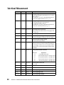
Vertical Movement . . . . . . . . . . . . . . . . . . . . . . . . . . . . . . . . . . . . . . . . . . . . . . . . . 74
Line Spacing . . . . . . . . . . . . . . . . . . . . . . . . . . . . . . . . . . . . . . . . . . . . . . . . . . . . . 74
Page Format . . . . . . . . . . . . . . . . . . . . . . . . . . . . . . . . . . . . . . . . . . . . . . . . . . . . . . 75
Printer Control . . . . . . . . . . . . . . . . . . . . . . . . . . . . . . . . . . . . . . . . . . . . . . . . . . . . 75
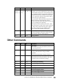
Other Commands . . . . . . . . . . . . . . . . . . . . . . . . . . . . . . . . . . . . . . . . . . . . . . . . . . 76
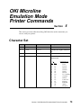
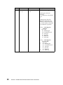
Section 5 - OKI Microline Mode Printer Commands
79
Character Set . . . . . . . . . . . . . . . . . . . . . . . . . . . . . . . . . . . . . . . . . . . . . . . . . . . . . . . . . . . 79
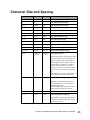
Character Size and Spacing . . . . . . . . . . . . . . . . . . . . . . . . . . . . . . . . . . . . . . . . . . . 81
Character Style . . . . . . . . . . . . . . . . . . . . . . . . . . . . . . . . . . . . . . . . . . . . . . . . . . . . . . . . . 82
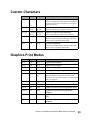
Custom Characters . . . . . . . . . . . . . . . . . . . . . . . . . . . . . . . . . . . . . . . . . . . . . . . . . 83
Graphics Print Modes . . . . . . . . . . . . . . . . . . . . . . . . . . . . . . . . . . . . . . . . . . . . . . . . . . . . . 83
Horizontal Movement . . . . . . . . . . . . . . . . . . . . . . . . . . . . . . . . . . . . . . . . . . . . . . . . . . . . 85
Vertical Movement . . . . . . . . . . . . . . . . . . . . . . . . . . . . . . . . . . . . . . . . . . . . . . . . . 88
Other Commands . . . . . . . . . . . . . . . . . . . . . . . . . . . . . . . . . . . . . . . . . . . . . . . . . . 89
Section 6 - Using the Printer Interface . . . . . . . . . . . 91
Parallel Interface . . . . . . . . . . . . . . . . . . . . . . . . . . . . . . . . . . . . . . . . . . . . . . . . . . . . . . . . 91
Parallel Interface Voltage Levels. . . . . . . . . . . . . . . . . . . . . . . . . . . . . . . . . . . . . . . . 91
Computer to Printer Communication . . . . . . . . . . . . . . . . . . . . . . . . . . . . . . . . . . . . 92
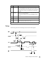
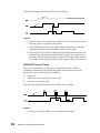
Timing . . . . . . . . . . . . . . . . . . . . . . . . . . . . . . . . . . . . . . . . . . . . . . . . . . . . . . . . . . . . 95
Serial Interface . . . . . . . . . . . . . . . . . . . . . . . . . . . . . . . . . . . . . . . . . . . . . . . . . . . . . . . . . . 96
Serial Interface Option. . . . . . . . . . . . . . . . . . . . . . . . . . . . . . . . . . . . . . . . . . . . . . . . 96
How to Connect the RS-232C Serial Interface . . . . . . . . . . . . . . . . . . . . . . . . . . . . . 96
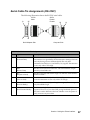
Serial Cable Pin Assignments (RS-232C) . . . . . . . . . . . . . . . . . . . . . . . . . . . . . . . . . 97
Serial Interface Cable (RS-232C) . . . . . . . . . . . . . . . . . . . . . . . . . . . . . . . . . . . . . . . 98
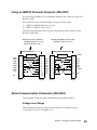
Using an IBM AT Personal Computer (RS-232C) . . . . . . . . . . . . . . . . . . . . . . . . . . 99
Universal Serial Bus Interface . . . . . . . . . . . . . . . . . . . . . . . . . . . . . . . . . . . . . . . . . . . . . . 99
Serial Communication Parameters (RS-232C) . . . . . . . . . . . . . . . . . . . . . . . . . . . . 100
v
Serial Computer Configuration Recommendations (RS-232C) . . . . . . . . . . . . . . . 103
Section 7 - Downloading Characters and Fonts . . 105
248x Printers . . . . . . . . . . . . . . . . . . . . . . . . . . . . . . . . . . . . . . . . . . . . . . . . . . . . . . . . . . 105
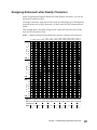
Designing Draft and NLQ Characters . . . . . . . . . . . . . . . . . . . . . . . . . . . . . . . . . . . 105
Designing Fast Draft Characters . . . . . . . . . . . . . . . . . . . . . . . . . . . . . . . . . . . . . . . 109
Designing NLQ II Characters . . . . . . . . . . . . . . . . . . . . . . . . . . . . . . . . . . . . . . . . . 109
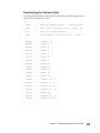
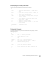
Downloading Characters . . . . . . . . . . . . . . . . . . . . . . . . . . . . . . . . . . . . . . . . . . . . . 109
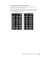
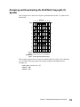
Designing and Downloading the Draft/NLQ Copyright (©) Symbol . . . . . . . . . . . 113
249x Printers . . . . . . . . . . . . . . . . . . . . . . . . . . . . . . . . . . . . . . . . . . . . . . . . . . . . . . . . . . 120
Designing and Downloading Characters . . . . . . . . . . . . . . . . . . . . . . . . . . . . . . . . . 120
Managing the Download Area. . . . . . . . . . . . . . . . . . . . . . . . . . . . . . . . . . . . . . . . . 124
Designing Monospaced Fast Draft Characters . . . . . . . . . . . . . . . . . . . . . . . . . . . . 125
Designing Monospaced Draft Characters . . . . . . . . . . . . . . . . . . . . . . . . . . . . . . . . 130
Designing Proportionally Spaced Characters . . . . . . . . . . . . . . . . . . . . . . . . . . . . . 135
Designing Enhanced Letter Quality Characters . . . . . . . . . . . . . . . . . . . . . . . . . . . 141
Section 8 - Barcodes. . . . . . . . . . . . . . . . . . . . . . . . . 147
Barcode Function . . . . . . . . . . . . . . . . . . . . . . . . . . . . . . . . . . . . . . . . . . . . . . . . . . . . . . . 147
Data Transfer Command . . . . . . . . . . . . . . . . . . . . . . . . . . . . . . . . . . . . . . . . . . . . . . . . . 152
Barcode Symbologies . . . . . . . . . . . . . . . . . . . . . . . . . . . . . . . . . . . . . . . . . . . . . . . . . . . . 153
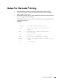
Notes For Barcode Printing . . . . . . . . . . . . . . . . . . . . . . . . . . . . . . . . . . . . . . . . . . . . . . . 179
Section 9 - Code Pages . . . . . . . . . . . . . . . . . . . . . . 187
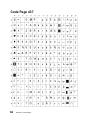
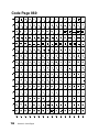
Code Page 437 . . . . . . . . . . . . . . . . . . . . . . . . . . . . . . . . . . . . . . . . . . . . . . . . . . . . . . . . . 188
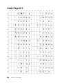
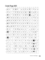
Code Page 437G . . . . . . . . . . . . . . . . . . . . . . . . . . . . . . . . . . . . . . . . . . . . . . . . . . . . . . . . 189
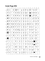
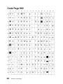
Code Page 813 . . . . . . . . . . . . . . . . . . . . . . . . . . . . . . . . . . . . . . . . . . . . . . . . . . . . . . . . . 190
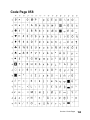
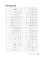
Code Page 850 . . . . . . . . . . . . . . . . . . . . . . . . . . . . . . . . . . . . . . . . . . . . . . . . . . . . . . . . . 191
Code Page 851 . . . . . . . . . . . . . . . . . . . . . . . . . . . . . . . . . . . . . . . . . . . . . . . . . . . . . . . . . 192
Code Page 853T . . . . . . . . . . . . . . . . . . . . . . . . . . . . . . . . . . . . . . . . . . . . . . . . . . . . . . . . 193
Code Page 857 . . . . . . . . . . . . . . . . . . . . . . . . . . . . . . . . . . . . . . . . . . . . . . . . . . . . . . . . . 194
Code Page 858 . . . . . . . . . . . . . . . . . . . . . . . . . . . . . . . . . . . . . . . . . . . . . . . . . . . . . . . . . 195
Code Page 860 . . . . . . . . . . . . . . . . . . . . . . . . . . . . . . . . . . . . . . . . . . . . . . . . . . . . . . . . . 196
Code Page 861 . . . . . . . . . . . . . . . . . . . . . . . . . . . . . . . . . . . . . . . . . . . . . . . . . . . . . . . . . 197
Code Page 863 . . . . . . . . . . . . . . . . . . . . . . . . . . . . . . . . . . . . . . . . . . . . . . . . . . . . . . . . . 198
Code Page 865 . . . . . . . . . . . . . . . . . . . . . . . . . . . . . . . . . . . . . . . . . . . . . . . . . . . . . . . . . 199
Code Page 869 . . . . . . . . . . . . . . . . . . . . . . . . . . . . . . . . . . . . . . . . . . . . . . . . . . . . . . . . . 200
Code Page 920 . . . . . . . . . . . . . . . . . . . . . . . . . . . . . . . . . . . . . . . . . . . . . . . . . . . . . . . . . 201
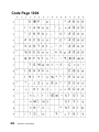
Code Page 1004 . . . . . . . . . . . . . . . . . . . . . . . . . . . . . . . . . . . . . . . . . . . . . . . . . . . . . . . . 202
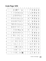
Code Page 1053 . . . . . . . . . . . . . . . . . . . . . . . . . . . . . . . . . . . . . . . . . . . . . . . . . . . . . . . . 203
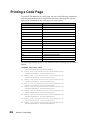
Printing a Code Page . . . . . . . . . . . . . . . . . . . . . . . . . . . . . . . . . . . . . . . . . . . . . . . . . . . . 204
Set Font Global, ESC [I . . . . . . . . . . . . . . . . . . . . . . . . . . . . . . . . . . . . . . . . . . . . . . 206
Character Sets 1 and 2 . . . . . . . . . . . . . . . . . . . . . . . . . . . . . . . . . . . . . . . . . . . . . . . . . . . 215
vi
Character Set 1. . . . . . . . . . . . . . . . . . . . . . . . . . . . . . . . . . . . . . . . . . . . . . . . . . . . . 216
Character Set 2. . . . . . . . . . . . . . . . . . . . . . . . . . . . . . . . . . . . . . . . . . . . . . . . . . . . . 217
Glossary . . . . . . . . . . . . . . . . . . . . . . . . . . . . . . . . . . . 219
Index . . . . . . . . . . . . . . . . . . . . . . . . . . . . . . . . . . . . . . 221
vii
viii
Introduction
Section
1
Your dot-matrix printer is an easy-to-use desktop printer that provides lowcost, high-quality output from your personal computer. It handles cut forms,
document-on-demand, and continuous form applications.
Your printer is a wire-matrix printer. The printer makes impressions by forcing
a hardened wire against an ink ribbon to transfer ink to the paper on impact. A
dot is printed each time the wire strikes the ribbon against the paper. This
impact printing technology has unique capabilities. The information in this
manual enables you to fully use the capabilities of dot-matrix impact printing.
This book applies to the Lexmark Forms Printer 2400 Series dot-matrix family
of printers. Differences that occur between printer models are noted.
The information in this manual is intended primarily for hardware and
software programmers, engineers, technicians, and others who require indepth technical information. If you need information to operate your printer,
see your User’s Guide.
Section 1: Introduction
7
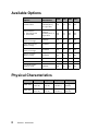
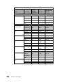
Available Options
2480
2481
2490
2491
1329605 (10 ft.),
1427498 (20 ft.),
or equivalent
Yes
Yes
Yes
Yes
12T0154
1038693 (50 ft), or
equivalent
Yes
Yes
Yes
Yes
Yes
Yes
Yes
Yes
Auto Sheet FeederNarrow Carriage
12T0150
Yes
No
Yes
No
Auto Sheet FeederWide Carriage
12T0151
No
Yes
No
Yes
Tractor 2 FeederNarrow Carriage
12T0152
Yes
No
Yes
No
Tractor 2 FeederWide Carriage
12T0153
No
Yes
No
Yes
USB cable
12A2405
Yes
Yes
Yes
Yes
248x OKI emulation
12T0155
Yes
Yes
No
No
Cut Sheet Output
Support Stand
12T0014
Yes
Yes
Yes
Yes
Options
Part Number
Parallel Cable
Serial interface
• Internal RS-232
• Serial cable
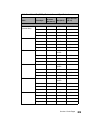
Physical Characteristics
8
Width
Height
Depth
Weight
2480/2490
491.5 mm
(18.75 in.)
195 mm
(7.36 in.)
290 mm
(11.28 in.)
8.0 kg
(14.8 lb)
2481/2491
633.5 mm
(24.35 in.)
195 mm
(7.36 in.)
290 mm
(11.28 in.)
9.8 kg
(18.7 lb)
Section 1: Introduction
Print Speeds
Your printer supports the following burst print speeds in characters per
second (cps).
Mode
2480/2481
2490/2491
Fast Draft
• 10 cpi
• 12 cpi
• 438 cps
• 510 cps
• 409 cps
• 465 cps
Draft
• 10 cpi
• 12 cpi
• 309 cps
• 304 cps
• 274 cps
• 328 cps
• 77 cps
• 76 cps
• 91 cps
• 109 cps
N/A
91 cps
Near Letter Quality Gothic, Courier
• 10 cpi
• 12 cpi
Letter Quality Prestige, Presentor,
Orator, and Script
• 10 cpi
Printhead Description
Your printer uses dot-matrix impact technology to generate characters. The 248x
has a 9-wire printhead. The 249x has a 24-wire printhead.
248x
The 248x printhead has nine wires arranged in a single vertical column. The
diameter of each wire is 0.30 mm (0.012 in.). The center-to-center distance
between wires is 0.353 mm (1/72 in.). The printhead has an impact force
sufficient to generate readable copies on multipart forms and envelopes up to
and including 6-ply forms (original plus 5 copies).
249x
The 249x printhead has twenty-four wires arranged in two parallel vertical
columns of twelve wires each. The diameter of each wire is 0.22 mm (0.009 in.).
The wires in each of the rows are vertically separated to produce a 0.141 mm (1/
180 in.) space between the centers of adjacent dots. The printhead has an impact
force sufficient to generate readable copies on multipart forms and envelopes
up to and including 4-ply forms (original plus 3 copies).
Section 1: Introduction
9
Printhead Movement
The printhead moves by a direct-current stepper motor.
The printhead can print while moving in both directions (bidirectional print).
When the printhead is printing in both directions, it automatically finds the
shortest path to print the next line.
The maximum velocity of the printhead is 1117.6 mm (44 in.) per second for the
248x and 1041.4 mm (41 in.) per second for the 249x.
Environmental Conditions
Optimum Temperature Ranges
Condition
Operating
Stored
Shipping
Ambient air
temperature
range
+10° to +40.6°C
(+50° to +105°F)
+1° to +60°C
+34° to +140°F
-40° to +60°C
(-40° to +140°F)
Humidity range
8.0% to 90%
5.0% to 100%
5.0% to 100%
Vibration
Although this desktop printer is portable and durable, do not operate or place
the printer in vibration-prone areas. For best results, operate the printer on a
level surface.
Clearances
Printer operation produces natural convection, or airflow. To allow sufficient
airflow, make sure there is 50.8 mm (2 in.) of space around all exposed surfaces.
Power Requirements
Power Consumption
•
•
10
38 W average operating power
7 W average idle power
Section 1: Introduction
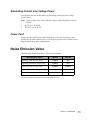
Alternating Current Line Voltage Power
Your printer uses one of the following alternating current (ac) line voltage
power values.
Note: Input voltage value varies with the country where the printer was purchased.
•
•
90-137 V ac, 50/60 Hz
180-265 V ac, 50/60 Hz
Power Cord
Printers for the United States and Canada have a 1.83 m (6.0 ft) power cord.
Printers for all other countries have a 2.74 m (9.0 ft) power cord, with the correct
plug to match the country requirements.
Noise Emission Value
The following are noise emission values for your printer.
Noise Emission Values
248x-001
249x-001
Operating 4 Mic Average, Draft
57 dB(A)
N/A
Operating Front Mic Average, Draft
56 dB(A)
N/A
Operating 4 Mic Average, NLQ
54 dB(A)
55 dB(A)
Operating Front Mic Average, NLQ
53 dB(A)
53 dB(A)
0 dB(A)
0 dB(A)
IDLE (standby mode)
All measurements were made in accordance with ISO 7779.
Section 1: Introduction
11
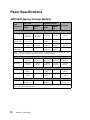
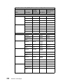
Paper Specifications
2480/2490 (Narrow Carriage Models)
Cut Forms
Paper
Dimensions
Single
Continuous Forms
Multiple
part
Single
Multiple
part
Envelopes
Width
Maximum
297 mm
(11.7 in.)
See Note
297 mm
(11.7 in.)
See Note
254 mm
(10 in.)
254 mm
(10 in.)
241 mm
(9.5 in.)
Maximum
Hole to Hole
N/A
See Note
N/A
241 mm
(9.5 in.)
241 mm
(9.5 in.)
N/A
76 mm
(3.0 in.)
76 mm
(3.0 in.)
76 mm
(3.0 in.)
76 mm
(3.0 in.)
152 mm
(6.0 in.)
N/A
N/A
63 mm
(2.5 in.)
63 mm
(2.5 in.)
N/A
Minimum
Minimum
Hole to Hole
Note: When the optional Auto Sheet Feeder or Tractor 2 Feeder is installed, the maximum width of a cut form is 215 mm (8.5 in.) for manual loading.
Page Length
Maximum
559 mm
(22.0 in.)
559 mm
(22.0 in.)
559 mm
(22.0 in.)
559 mm
(22.0 in.)
152 mm
(6.0 in.)
Minimum
76 mm
(3.0 in.)
76 mm
(3.0 in.)
3.2 mm
(0.125 in.)
3.2 mm
(0.125 in.)
110 mm
(4.1 in.)
Maximum
g/m2
90
(24 lb.)
N/A
90 g/m2
(24 lb.)
N/A
90 g/m2
(24 lb.)
Minimum
60 g/m2
(16 lb.)
N/A
56 g/m2
(15 lb.)
N/A
75 g/m2
(20 lb.)
Weight
Thickness - Multiple Part Forms of 45 g/m2 (12 lb.) paper
0.058 mm
(0.0023 in.)
See Note
0.058 mm
(0.0023 in.)
See Note
0.042 mm
(0.017 in.)
Note: Thickness up to 0.512 mm (0.0202 in.) for 2480/2481 printers; up to0.36 mm
(0.015 in.) for 2490/2491 printers.
12
Section 1: Introduction
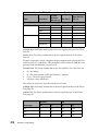
2481/2491 (Wide Carriage Models)
Cut Forms
Paper
Dimensions
Single
Continuous Forms
Multiple
part
Single
Envelopes
Multiple
part
Width
Maximum
420 mm
(16.5 in.)
420 mm
(16.5 in.)
406 mm
(16.0 in.)
406 mm
(16.0 in.)
241 mm
(9.5 in.)
Maximum
Hole to Hole
N/A
N/A
393 mm
(15.5 in.)
393 mm
(15.5 in.)
N/A
Minimum
76 mm
(3.0 in.)
76 mm
(3.0 in.)
76 mm
(3.0 in.)
76 mm
(3.0 in.)
152 mm
(6.0 in.)
Minimum
Hole to Hole
N/A
N/A
63 mm
(2.5 in.)
63 mm
(2.5 in.)
N/A
Page Length
Maximum
559 mm
(22.0 in.)
559 mm
(22.0 in.)
559 mm
(22.0 in)
559 mm
(22.0 in.)
152 mm
(6.0 in.)
Minimum
76 mm
(3.0 in.)
76 mm
(3.0 in.)
3.2 mm
(0.125 in.)
3.2 mm
(0.125 in.)
110 mm
(4.1 in.)
Maximum
g/m2
90
(24 lb.)
N/A
90 g/m2
(24 lb.)
N/A
90 g/m2
(24 lb.)
Minimum
60 g/m2
(16 lb.)
N/A
56 g/m2
(15 lb.)
Weight
75 g/m2
(20 lb.)
Thickness - Multiple Part Forms of 45 g/m2 (12 lb.) paper
0.058 mm
(0.0023 in.)
See Note
0.058 mm
(0.0023 in.)
See Note
0.053 mm
(0.021 in.)
Note: Thickness up to 0.512 mm (0.0202 in.) for 2480/2481 printers; up to0.36 mm
(0.015 in.) for 2490/2491 printers.
Section 1: Introduction
13
Paper Size
Narrow carriage (2480/2490)
Wide carriage (2481/2491)
Automatic Feed Mode (single-part form)
Length
139.7 mm (5.5 in.)
minimum
139.7 mm (5.5 in.)
minimum
355.6 mm (14.0 in.)
maximum
355.6 mm (14.0 in.) (See Note 1)
maximum
558.8 mm (22 in.) (See Note 2)
Width
105 mm (4.13 in.)
minimum
105 mm (4.13 in.)
minimum
215.9 mm (8.5 inch)
maximum
364 mm (14.3 in.)
maximum
Tractor Feeder (continuous forms)
Length
Width
76 mm (3.0 in.)
minimum
76 mm (3.0 in.)
minimum
N/A
maximum
N/A
maximum
76 mm (3.0 in.)
minimum
76 mm (3.0 in.)
minimum
254 mm (10 in.)
maximum
406 mm (16.0 in.)
maximum
Notes:
1 For paper width greater than 8.5 inches.
2 For paper width up to 8.5 inches.
Manual Feed (cut sheets)
Length
Width
Paper Weight
14
76.2 mm (3.0 in.)
minimum
76.2 mm (3.0 in.)
minimum
558.8 mm (22.0 in.)
maximum
558.8 mm (22.0 in.)
maximum
76.2 mm (3.0 in.)
minimum
76.2 mm (3.0 in.)
minimum
279.4 mm (11.0 in.)
maximum
420 mm (16.5 in.)
maximum
16 ~ 24 lbs (60 ~ 90 g/m2)
Section 1: Introduction
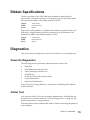
Ribbon Specifications
The life expectancy of the 2300/2400 series standard re-inking ribbon is
approximately 4 million characters in 10 characters per inch (cpi) draft mode.
For replacement ribbon, order ribbon number 11A3540.
Length:
1.8 m (6.0 ft)
Width:
8 mm (0.315 in.)
Fabric:
Nylon
High yield re-inking ribbon is available for the 2400 series printer. It has a life
expectancy of approximately 8 million characters in 10 cpi draft mode. For
replacement ribbon, order ribbon number 11A3550.
Length:
2.5 m (8.3 ft)
Width:
8 mm (0.315 in.)
Fabric:
Nylon
Diagnostics
This section discusses diagnostics at power-on and how to do the printer test.
Power-On Diagnostics
The following tests are performed when the printer is turned On.
•
•
•
•
•
•
•
RAM Test
Font ROM/Microcode Sum Test
Timer/Interrupt Controller Test
NVRAM Test
Switch Scan Test of the operator panel
Carrier Initialization
Paper Feed Initialization
If any errors occur during the tests, a combination of blinking LEDs indicate
which test failed.
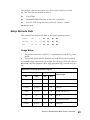
Printer Test
You can run a Printer Test to aid in problem determination. In addition to the
normal power-on internal tests (see “Power-On Diagnostics” on page 15), the
printer test generates a sample printout.
This test printout can be printed either with or without connecting the printer to
your computer.
Section 1: Introduction
15
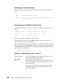
To run the printer test, follow these steps:
1
2
3
4
Make sure the paper and ribbon are installed.
Turn the printer Off.
Press Line Feed while you turn the printer On.
After a few seconds, release Line Feed.
To stop or interrupt the printer test:
1
Press Start/Stop. The test stops after a complete line of characters has
printed.
2
Press Start/Stop to continue the printer test.
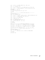
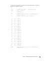
Programming Examples
Examples in this manual have been formatted to be processed by a simple
BASIC program. The BASIC program reads an input file and writes data to an
output file. Printer commands may be entered into the input file in a
hexadecimal format and enclosed with opening and closing delimiters.
The opening delimiter is a less-than symbol, ’<’, followed by an ’x’. The ’x’ may
be either upper or lower case. The closing delimiter is a greater-than symbol,
’>’.
Within the delimiters, hexadecimal data must be presented in two-digit pairs.
White space, blanks, carriage returns and line feeds may be used between the
pairs. In addition, a comment may be added to the end of a line by using a
minus sign, ’-’, at the start of the comment. All data after a minus sign is ignored
until a carriage return or line feed is encountered.
The example format used in this book is shown below:
<x
1B36
- select character set 2
1B5B0400000001B5
- select code page 437
1B5B640100A0
- set print quality to letter quality
1B5B4905000055007801
- set font global to Courier 12
>
All of the examples use this encoding method and have been tested using the
following BASIC program:
1000
1010
1020
1030
1040
16
INPUT "Enter file name to be printed"; FILENAME$
OPEN FILENAME$ FOR INPUT AS #1
OPEN "prtrout.bin" FOR OUTPUT AS #2
WHILE EOF(1) = 0
I$ = INPUT$(1, #1)
Section 1: Introduction
1050
1060
1070
1080
1090
1100
1110
1120
1130
1140
1150
1160
1170
1180
1190
1200
1210
1220
1230
1240
1250
1260
1270
1280
1290
1300
1310
1320
1330
1340
1350
IF(I$ <> "<")THEN PRINT #2,I$;: GOTO 1090
I$ = INPUT$(1, #1)
IF(I$ = "x")OR (I$ = "X") THEN GOSUB 1130: GOTO 1090
IF(I$ = "<")THEN PRINT#2,I$;: GOTO 1090 ELSE GOTO 1290
WEND
CLOSE #1: CLOSE #2:
SHELL "copy prtrout.bin/b lpt1 >nul"
END
'--------------------process hex mode data------------WHILE EOF(1) = 0
I$ = INPUT$(1, #1)
IF(I$ = " ")OR(I$ = CHR$(10))OR(I$ = CHR$(13))THEN GOTO 1230
IF(I$ = "-")THEN GOSUB 1300: GOTO 1230
IF(I$ = ">") THEN RETURN
GOSUB 1250: N1 = N
IF EOF(1) GOTO 1290
I$ = INPUT$(1,#1): GOSUB 1250
PRINT #2,CHR$((N1 * 16) + N);
WEND
RETURN
'--------------------hex digit conversion-------------IF(I$ >= "0") AND (I$ <= "9")THEN N= ASC(I$)-48:RETURN
IF(I$ >= "A") AND (I$ <= "F") THEN N= ASC(I$)-55:RETURN
IF(I$ >= "a") AND (I$ <= "f")THEN N= ASC(I$)- 87: RETURN
PRINT "Invalid hexadecimal data - [" + I$ + "]": STOP
'----------------comments bypass subroutine-----------WHILE EOF(1) = 0
I$ = INPUT$(1, #1)
IF (I$ = CHR$(10)) OR (I$ = CHR$(13)) THEN RETURN
WEND
GOTO 1100
Section 1: Introduction
17
18
Section 1: Introduction
Set Initial
Conditions (SIC)
Command
Section
2
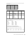
The SIC command sets the printer to the default values that were set at the
factory or to user-defined defaults.
SIC Command Format
Use the following format:
Format
ESC [
K
Ln Hn init ID p1...p22
Decimal
27
91
75
Ln Hn
Hex
1B
5B
4B
Ln Hn
Ln is the number of parameters plus 2. Hn is 0.
The decimal and hexadecimal digits for the printer command appear below the
printer command format.
Section 2: Set Initial Conditions (SIC) Command
21
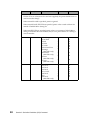
init sets the printer to user-defined or factory settings. The value for init can be:
22
Initial Values
Description
0
Initializes printer to user-defined settings. The download font
remains unchanged. If parameters are specified, they overwrite the default settings. If the emulation mode is changed,
the download font is initialized. This command only copies
data from the selected macro, add parameter changes, if any,
and store in working RAM; the data stored in the macro’s nonvolatile RAM is not affected.
1
Initializes printer to user-defined settings. The download font
is initialized. If parameters are specified, they overwrite the
default settings. This command only copies data from the
selected macro, add parameter changes, if any, and store in
working RAM; the data stored in the macro’s non-volatile
RAM is not affected.
4
Initializes printer to factory settings. The download font
remains unchanged. If parameters are specified, they overwrite the default settings. If the emulation mode is changed,
the download font is initialized. This command only copies the
default settings from ROM, add parameter changes, if any, and
store in working RAM; the data stored in the macro’s non-volatile RAM is not affected.
5
Initializes printer to factory settings. The download font is initialized. If parameters are specified, they overwrite the default
settings. This command only copies the default settings from
ROM, add parameter changes, if any, and store in working
RAM; the data stored in the macro’s non-volatile RAM is not
affected.
254
Initializes printer to user-defined settings. The download font
is initialized. If parameters are specified, they overwrite the
default settings. This command changes data stored in the
selected macro. It copies data from the selected macro, add
parameter changes, if any, and store in working RAM and in
the selected macro. It also changes the default macro to the
value of parm 3.
255
Initializes printer to default settings. The download font is initialized. If parameters are specified, they overwrite the default
settings. This command changes data stored in the macro’s
non-volatile RAM. It copies default settings from ROM, add
parameter changes, if any, and store in working RAM and all
macros. It also sets the default macro to Disable.
Section 2: Set Initial Conditions (SIC) Command
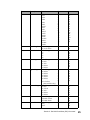
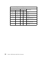
Use the following parameters (parms) with SIC commands that use the printer
ID of C5 and C6:
Printer
Dec
Hex
2480
197
C5
2481
197
C5
2490
198
C6
2491
198
C6
Parm
Description
Selection
Dec
Hex
1
Emulation
0=No Change
1=PPDS
2=Epson
0
1
2
00
01
02
2
Panel Disable
(see Note 1)
3
Macro
(see Note 2)
0=No Change
1=Panel Disabled
2=Panel Enabled
0=No Change
1=Macro 1
2=Macro 2
3=Macro 3
4=Macro 4
255=Disable Macro
0
1
2
0
1
2
3
4
255
00
01
02
00
01
02
03
04
FF
Notes:
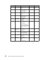
1 You can disable specific buttons on the operator panel. The upper 6 bits of parm 2
represent the different buttons on the operator panel. The lower 2 bits are reserved
to enable or disable the panel.
Bit
7. Font
6. Pitch
5. Micro Ç
4. Micro È
3. LF
2. Macro
Off
Disabled
Disabled
Disabled
Disabled
Disabled
Disabled
On
Enabled
Enabled
Enabled
Enabled
Enabled
Enabled
Bits 0 and 1 allow for existing panel disable functions.
To disable the panel or any of the buttons, bit 0 must be On.
The Start/Stop button and the Form Feed button are always enabled.
In the following example the Micro Ç and Micro È buttons are enabled:
Format
Decimal
Hex
ESC
27
1B
[
91
5B
K
75
4B
Ln
04
04
Hn
00
00
init
254
FE
ID
197
C5
P1
00
00
P2
49
31
Section 2: Set Initial Conditions (SIC) Command
23
Parm
Description
Selection
Dec
Hex
Notes (cont.):
2 If Parm 3 has no value (macro has not been supplied), the printer default macro is
used to store the change.
When init=04H or 05H is specified, parm3 is ignored.
When init=00H, 01H, FEH, FFh are specified, parm3 value is used as Macro No.
instead of Default Macro setting No.
When init=FEH, FFh are specified parm3 value is overwritten to Default Macro
setting in NVRAM. When the disable(=255) is set to parm3 Macro No.1 setting is
used to initialize.
4
5
24
Font
Pitch
0=No Change
1=Fast Draft
2=Draft
3=Gothic
4=Courier
5=Download Font
6=Prestige
(249x Plus only)
7=Presentor
(249x Plus only)
8=Orator
(249x Plus only)
9=Script
(249x Plus only)
0=No Change
1=10 Pitch
2=12 Pitch
3=15 Pitch
4=17.1 Pitch
5=20 Pitch
6=PS
7=24 Pitch
(249x Plus only)
Section 2: Set Initial Conditions (SIC) Command
0
1
2
3
4
5
6
00
01
02
03
04
05
06
7
07
8
08
9
09
0
1
2
3
4
5
6
7
00
01
02
03
04
05
06
07
Parm
6
Description
Selection
Dec
Hex
Code Page
0=No Change
1=437
2=850
0
1
2
3
4
5
6
7
8
9
10
11
12
13
14
15
00
01
02
03
04
05
06
07
08
09
0A
0B
0C
0D
0E
0F
0
1
0
1
2
3
4
0
1
2
3
4
00
01
00
01
02
03
04
00
01
02
03
04
0
1
2
3
4
5
6
00
01
02
03
04
05
06
0
1
2
3
4
5
0
1
2
0
1
2
00
01
02
03
04
05
00
01
02
00
01
02
3=860
7
Form Length
8
Lines Per Inch
9
Left Margin
10
11
12
13
Right Margin
4=863
5=865
6=437G
7=813
8=851
9=853T
10=857
11=869
12=920
13=1053
14=861
15=1004
16=858
0=No Change
1=1 to 176 Lines
0=No Change
1=3
2=4
3=6
4=8
0=No Change
1=0 Inch
2=1 Inch
3=2 Inches
4=3 Inches
0=No Change
1=4 Inches
2=5 Inches
3=6 Inches
4=7 Inches
5=8 Inches
6=13.6 Inches
(2491 models only)
Bottom Margin 0=No Change
1=0 Inch
2=1/2 Inch
3=1 Inch
4=2 Inches
5=3 Inches
Alarm
0=No Change
1=Disable Alarm
2=Enable Alarm
Auto CR
0=No Change
1=On
2=Off
Section 2: Set Initial Conditions (SIC) Command
25
Parm
Description
14
Auto LF
15
16
17
18
19
20
21
22
23
26
Selection
0=No Change
1=On
2=Off
Slash Zero
0=No Change
1=Slashed Zero
2=Normal Zero
Character Set
0=No Change
1=Set 1
2=Set 2
Print Direction 0=No Change
1=Unidirectional
2=Bidirectional
Sheet Feeder
0=No Change
1=Disable
2=Enable
Lock
0=No Change
1=Font Lock
2=Pitch Lock
3=Font and Pitch Lock
4=Font and Pitch Unlock
254=SIC Command Lock
254=SIC Command
Unlock
FF Enable
0=No Change
(2480 only)
1=Ignore FF
2=Honor FF
TOF Read
0=No Change
1=TOF Read Disable
2=TOF Read Enable
Tractor
0=No Change
1=Tractor 1
2=Tractor 2
Tear Off
0=No Change
1=On
2=Off
3=One Second
Section 2: Set Initial Conditions (SIC) Command
Dec
Hex
0
1
2
0
1
2
0
1
2
0
1
2
0
1
2
0
1
2
3
4
5
6
00
01
02
00
01
02
00
01
02
00
01
02
00
01
02
00
01
02
03
04
05
06
0
1
2
0
1
2
0
1
2
0
1
2
00
01
02
00
01
02
00
01
02
00
01
02
IBM Emulation
Mode Printer
Commands
3
Section
This section provides a detailed description of IBM emulation mode
commands you can use with your printer.
Control Codes
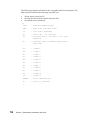
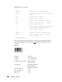
Control codes are one-character printer commands that are used to:
•
•
•
Manage the printing of a job.
Control the movement of the cursor, which changes the current print
position.
Control primary and secondary font selection.
The first 32 characters of the Standard ASCII table are control codes. This
printer uses the following control codes.
Code
Name
Symbol
Description
Value
(Dec)
Value
(Hex)
Null
NUL
Null character.
0
00
Sound
Beeper
BEL
Sounds the printer beeper for
approximately 1 second.
7
07
Backspace BS
Causes the printer to move the current
8
print position one character position to the
left.
08
Horizontal HT
Tab
Moves the printhead to the horizontal
tabulation stops.
09
Line Feed LF
Advances the paper one line on the page. 10
0A
Vertical Tab VT
Moves the paper to the next vertical
tabulation stop set with the printer
command Set Vertical Tabulation Stops
(ESC B).
11
0B
Advances the paper to the top of the next
12
page and does a carriage return.
0C
Form Feed FF
9
Section 3: IBM Emulation Mode Printer Commands
27
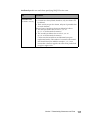
Code
Name
Value
(Dec)
Value
(Hex)
Symbol
Description
CR
Moves the current print position to the left 13
margin of the current line.
0D
SO
DoubleWide
Printing by
Line
Prints all characters in double-width
mode.
14
0E
Condensed SI
Printing
Condenses printing from 10 characters per 15
inch (cpi) to 17.1 and 12 cpi to 20.
0F
Select
Printer
DC1
Selects the printer.
17
11
Select 10
cpi
DC2
Returns condensed printing to normal (10 18
cpi)
12
Deselect
Printer
DC3
Signals the printer to stop accepting data 19
from the computer. This control code has
no effect on the parallel interface.
13
DC4
Cancel
DoubleWide
Printing by
Line
Cancels double-width printing mode and 20
returns printing to normal.
14
Cancel
Data
CAN
Clears current line buffer of data already 24
received to print on the current line since
last Form Feed, Line Feed, Carrier Return,
or Cancel.
18
Space
SP
Moves the print position one character
space to the right.
20
Carriage
Return
32
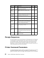
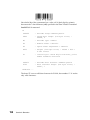
Escape Sequences
An escape sequence (two or more characters of information) lets you change the
way the printer is currently printing. Like a control code, it gives you control
over the printed output. The escape sequence begins with the character ESC
(decimal 027, hexadecimal 1B). The printer recognizes this character as the
beginning of a printer command signalling that the information that follows is
control information and not data to be printed.
Printer Command Parameters
A command parameter sets the value for a command. This value stays constant
until either a different value resets the command or a command resets the
printer to its default values. For example, after the printer receives a command
28
Section 3: IBM Emulation Mode Printer Commands
that selects a right margin beginning at column 63, the right margin of each
printed page begins at column 63. The margin remains constant until a right
margin command with a different value resets the margin, or the printer is reset.
In this section, command parameters are indicated by a lowercase n. Usage
Notes explain how to compute this parameter.
Command Structure
The printer commands use ASCII; the decimal and hexadecimal digits are
shown for your convenience.
Most commands have the following structure (spaces have been added for
readability; do not include spaces when you type the command):
ESC & a n C data
&
a
n
C
data
Parameterized character from ASCII table range 33-47 decimal.
Group character from ASCII table range 96-126 decimal that
specifies a group type of control.
Value within specified numeric range, from ASCII table range
48-57, 45, 46 decimal. If a value is not specified, a value of 0
is assumed.
Termination character from ASCII table range 64-90
(47-122 w/chaining) decimal.
Binary 8-bit data (from graphics, and so on). The value field
specifies the number of bytes of binary data.
Section 3: IBM Emulation Mode Printer Commands
29
Example of IBM Emulation Mode Printer Command
Select Code Page (name of command)
(A short description of the command follows)
This command placed before the first character changes the active code page.
(The printer command format follows with the decimal and hexadecimal values).
Format
ESC [
T
4
0 0
0 Hc
Lc
Decimal
27
91
84
4
0 0
0 Hc
Lc
Hex
1B
5B
54
04 00 00 00 Hc
Lc
Usage Notes
The digits 4 0 0 0 (decimal), 04 00 00 00 (hexadecimal) are constants.
To calculate Hc Lc for a code page that is not shown:
•
•
•
Divide the code page number, such as 437, by 256.
— The whole number result is the Hc value.
— The remainder is the Lc value.
If your code page has an alphabetic character, such as 437G, add 10,000 to
the code page number, then divide by 256.
Code page information begins on page 188.
Related commands list other commands that can or should be used with the
printer command being described.
Usage Notes give additional information for that command, such as:
•
•
•
how the command reacts with other commands
any other command that is required, or that supplements the command
how the datastream is affected by the command
Pay attention to the uppercase (capital letter) and the lowercase letters. If the
format shows an uppercase letter, enter the command with an uppercase letter.
If the letter in the command format is lowercase, enter it as lowercase. The
printer looks at the uppercase and lowercase letters as separate command
instructions.
The uppercase letter O is different from the numeral 0 (zero). Notice that the
uppercase O is wider and rounder than the zero. To help you with this distinction, the text that describes the command shows the numeral 0 and also spells
out zero.
30
Section 3: IBM Emulation Mode Printer Commands
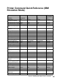
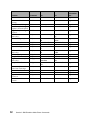
Printer Command Quick Reference (IBM
Emulation Mode)
Function
Command
Dec
Hex
For more
information
see...
Begin/End
Continous Underline
Set Line Space to 1/8 inch
Set Line Space to 7/72 inch
Activate Line Spacing for
Text
Set Line Spacing for
Graphics
Set Top of Form
Automatic Line Feed
Select Character Set 2
Select Character Set 1
Select 12 cpi
Download a Character Set
Set Line Spacing for Text
Set Vertical Tab Stops
Set Page Length in Lines
Set Page Length in Inches
Set Horizontal Tab Stops
Begin Emphasized (Bold)
Print
End Emphasized (Bold)
Print
Begin Double-Strike Print
End Double-Strike Print
Select Print Mode
Move PaperVertically
Normal Density Bit Image
Graphics
Dual-Density Bit Image
Graphics (Half-Speed)
Set Skip Perforation
Cancel Skip Perforation
Proportional Space Mode
Deselect Printer
Set Default Tab Stops
Begin Subscript/
Superscript
End Subscript/Superscript
ESC _
27 45 n
1B 2D n
page 47
ESC 0
ESC 1
ESC 2
27 48
27 49
27 50
1B 30
1B 31
1B 32
page 57
page 57
page 57
ESC 3
27 51 n
1B 33 n
page 58
ESC 4
ESC 5
ESC 6
ESC 7
ESC :
ESC =
ESC A
ESC B
ESC C
ESC C 0
ESC D
ESC E
27 52
27 53 n
27 54
27 55
27 58
27 61
27 65 n
27 66 n,n1,n2...
27 67 n
27 67 0 n
27 68 n,n1,n2... 0
27 69
1B 34
1B 35 n
1B 36
1B 37
1B 3A
1B 3D
1B 41 n
1B 42 n,n1,n2...
1B 43 n
1B 43 00 n
1B 44 n,n1,n2... 00
1B 45
page 59
page 55
page 33
page 33
page 40
page 35
page 57
page 56
page 59
page 59
page 53
page 44
ESC F
27 70
1B 46
page 44
ESC G
ESC H
ESC I
ESC J
ESC K
27 71
27 72
27 73
27 74 n
27 75 Ln Hn data
1B 47
1B 48
1B 49
1B 4A n
1B 4B Ln Hn data
page 44
page 44
page 40
page 55
page 49
ESC L
27 76 Ln Hn data
1B 4C Ln Hn data
page 51
ESC N
ESC O
ESC P
ESC Q
ESC R
ESC S
27 78 n
27 79
27 80
27 81
27 82
27 83 n
1B 4E n
1B 4F
1B 50
1B 51
1B 52
1B 53 n
page 60
page 60
page 58
page 61
page 53
page 45
ESC T
27 84
1B 54
page 45
Section 3: IBM Emulation Mode Printer Commands
31
Function
Command
Dec
Hex
For more
information
see...
Set Print Direction
ESC U
27 85
1B 55
page 45
Continuous Double-Wide
Printing
Set Horizontal Margins
Dual-Density Bit Image
Graphics (Normal Speed)
High-Density Bit Image
Graphics
Score Select
(249x only)
Select Print Type Style
ESC W
27 87
1B 57
page 46
ESC X
ESC Y
27 88 n1,n2
27 89 Ln Hn data
1B 58 n1,n2
1B 59 Ln Hn data
page 54
page 52
ESC Z
27 90 Ln Hn data
1B 5A Ln Hn data
page 52
ESC [ -
27 91 45 2 0 loc type
ESC [ @
Set Initial Condition
Select Global Font
Select Code Page
ESC [ K
ESC [ I
ESC [ T
Set Vertical Units
(249x only)
Set Print Quality
Setup Barcode Parameter
High Resolution Graphics
(249x only)
Setup Barcode Data
ESC [ \
Continuously Print Characters from Code Page
Reverse Line Feed
Print One Character
Begin/End Continuous
Overscore
Move Current Print
Position
32
ESC \
1B 5B 2D 02 00 loc
type
27 91 64 4 0 m1 0 m3 1B 5B 40 04 00 m1 00
m4
m3 m4
27 91 75 Ln Hn
1B 5B 4B Ln Hn
27 91 73 2 0 Hf Lf
1B 5B 49 02 00 Hf Lf
27 91 84 4 0 0 0 Hc 1B 5B 54 4 0 0 0 Hc Lc
Lc
27 91 92 4 0 0 0 Lu 1B 5B 5C 04 00 00 00
Hu
Lu Hu
27 91 100 1 0 m
1B 5B 64 01 00 n
27 91 102 6 0 k m s... 1B 5B 66 06 00 k m s...
1B 5B 67 Ln Hn mode
27 91 103 Ln Hn
data
mode data
27 91 112 Ln Hn
1B 5B 70 Ln Hn data
data
27 92 Ln Hn n1,n2... 1B 5C Ln Hn n1,n2...
ESC ]
ESC ^
ESC _
27 93
27 94 n
27 95 n
1B 5D
1B 5E n
1B 5F n
page 55
page 35
page 47
ESC d
27 100 Ln Hn
1B 64 Ln Hn
page 54
ESC [ d
ESC [ f
ESC [ g
ESC [ p
Section 3: IBM Emulation Mode Printer Commands
page 46
page 42
page 21
page 36
page 49
page 56
page 48
page 50
page 63
page 34
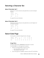
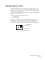
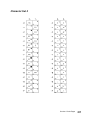
Selecting a Character Set
Select Character Set 1
Character set 1 contains characters and symbols that are used in the English
language.
Format
ESC 7
Decimal
27
55
Hex
1B
37
See pag e216 for more information.
Select Character Set 2
Character set 2 contains characters and symbols that are used in English and
non-English languages.
Format
ESC 6
Decimal
27
54
Hex
1B
36
See pag e217 for more information.
Select Code Page
Use this printer command to change the active code page.
Format
ESC [
T
4
0
0
0
Hc
Lc
Decimal
27
91
84
4
0
0
0
Hc
Lc
Hex
1B
5B
54
04
00
00
Hc
Lc
00
Usage Notes
The digits 4 0 0 0 (decimal), 04 00 00 00 (hexadecimal) are constants.
To calculate Hc Lc for a code page that is not shown:
•
•
Divide the code page number, such as 437, by 256.
— The whole number result is the Hc value.
— The remainder is the Lc value.
If your code page has an alphabetic character, such as 437G, add 10,000 to
Section 3: IBM Emulation Mode Printer Commands
33
•
the code page number, then divide by 256.
Code page information begins on page 188.
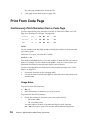
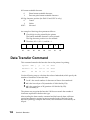
Print From Code Page
Continuously Print Characters from a Code Page
Use this command to print characters from the all Characters Chart of a Code
Page (see “Printing a Code Page” on page 204).
Format
ESC \
Ln
Hn
n1.....nn
Decimal
27
92
Ln
Hn
n1.....nn
Hex
1B
5C
Ln
Hn
n1.....nn
Ln Hn
Ln (low number) and Hn (high number) identify the number of characters that
you want to print.
See below for ways to calculate this variable.
n1 n2 n3......nn
The variables, n1 n2 n3 and so on, are the number of characters that you want to
print. For example, for each character, n1 n2 n3...., that you want to print, you
substitute the decimal or hexadecimal digit for that character.
Use the code page tables for the decimal or the hexadecimal digit (see “Code
Pages” on page 187).
•
•
Locate the character on the code page table.
Use the decimal or hexadecimal digit for that character in the printer command format.
Usage Notes
To print less than 256 characters:
•
•
Hn is 0.
Ln is the number of characters you want to print.
To print more than 256 characters:
•
34
Divide the number of characters you want to print by 256.
— The result is Hn.
— The remainder is Ln.
You must input a decimal or hexadecimal digit for each character
(n1.....nn) you want to print. The decimal and hexadecimal digits are
Section 3: IBM Emulation Mode Printer Commands
located in the code page tables beginning on page 188.
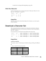
Print One Character
Use this command to print a character from the All Characters Chart of a Code
Page (see “Code Pages” on page 187).
Format
ESC ^
n
Decimal
27
94
n
Hex
1B
5E
n
Usage Note
Substitute the decimal or hexadecimal digit of the character you want to print
for the variable n.
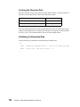
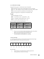
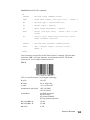
Download a Character Set
This command downloads a character set to the printer and starts a character
font image download. Up to 256 consecutive characters can be downloaded in
each ESC = sequence.
To download fonts, download must be enabled in the Setup menu.
Format
ESC =
count low/high id
start low/high data
Decimal
27
61
count low/high id
start low/high data
Hex
1B
3D
count low/high id
start low/high data
Usage Notes
count low/count high
The number of bytes of data being downloaded starting with the printer id byte.
id
A 1-byte number identifying the printer.
Printer
Dec
Hex
2480 Plus
182
B6
2481 Plus
184
B8
2490 Plus
183
B7
2491 Plus
185
B9
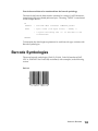
Section 3: IBM Emulation Mode Printer Commands
35
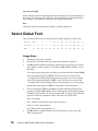
start low/start high
When character data is downloaded, the start address is the absolute address of
the start of the character data. When the lookup table data is downloaded, the
start address is the address of the new entry in the lookup table.
data
Character data from the character design, or lookup table data.
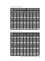
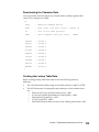
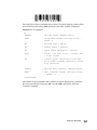
Select Global Font
This command allows you to vary the font and pitch typestyle within a file.
Format
ESC [
I
2
0
Hf
Lf
Hs
Ls
Sm
Nul Hc
Lc
Decimal 27
91
73
2
0
Hf
Lf
Hs
Ls
Sm
Nul Hc
Lc
Hex
5B
49
02
00
Hf
Lf
Hs
Ls
Sm
Nul Hc
Lc
1B
Usage Notes
•
•
•
The digits 2 and 0 are constants.
If Font Lock and Pitch Lock are active, this command is ignored.
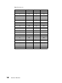
The Hf and Lf variables identify the pitch and font typestyle you want to
print. Tables 1 and 2 on page 37 describe the Hf and Lf variables. To use
the tables:
1 Locate the type style (pitch and font) you want in the left column (Pitch).
2 For the decimal digits for Hf Lf, look across the row to the second
through fifth columns (depending on the typestyle you want to print).
3 For the hexadecimal digits for Hf Lf, look across the row to the sixth
through ninth columns (depending on the typestyle you want to print).
4 Substitute these digits for Hf Lf in the printer command syntax.
•
The size parameters (Hs, Ls and Sm) are valid when the pitch and font
typestyle variables (Hf and Lf) are not valid and the size modifier parameter (Sm) is 1 (decimal) or 01 (hexadecimal). Table 3 on page 39 specifies the
pitch for valid size parameters. Other valid sizes for Sm include:
1 00 - No change
2 01 - Width is measured in 0.018 mm (1/1440 in.)
3 02, 03 - Font is porportional
4 All other values are regarded as 0.
•
36
The Hc and Lc variables identify the Code Page you want to use. (See
Table 4 on page 39.)
Section 3: IBM Emulation Mode Printer Commands
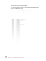
Table 1. 248x: Select Global Font
Decimal Hf Lf
Hex Hf Lf
Pitch
Normal Bold
Italic
Bold/Ital Normal Bold
italic
Bold/Ital
Courier
5
10
12
15
17
20
PS
0 244
0 11
1 235
1 236
1 237
1 238
0 171
0 245
0 46
0 108
0 214
0 253
0 18
0 92
0 215
0 57
0 116
0 216
0 184
0 172
0 185
Gothic
5
10
12
15
17
20
PS
0 241
0 36
1 143
1 142
1 141
1 140
0 174
0 242
0 39
0 110
0 110
0 220
0 157
0 109
0 109
0 162
00 F4
00 0B
01 EB
01 EC
01 ED
01 EE
00 AB
00 F5
00 2E
00 6C
00 D6
00 FD
00 12
00 5C
00 D7
00 39
00 74
00 D8
00 B8
00 AC
00 B9
00 F1
00 24
01 8F
01 8E
01 8D
01 8C
00 AE
00 F2
00 27
00 6E
00 6E
00 DC
00 9D
00 6D
00 6D
00 A2
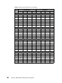
Table 2. 249x: Select Global Font
Decimal Hf Lf
Hex Hf Lf
Pitch
Normal Bold
Italic
Bold/Ital Normal Bold
italic
Bold/Ital
Courier
5
10
12
15
17
20
24
PS
0 244
0 11
1 235
1 236
1 237
1 238
1 30
0 171
5
10
12
15
17
20
24
PS
0 12
1 239
1 240
1 201
1 202
1 31
1 164
0 245
0 46
0 108
0 214
0 253
0 18
0 92
0 215
0 184
0 172
00 60
0 111
0 112
0 57
0 116
0 216
0 185
Prestige
00 F4
00 0B
01 EB
01 EC
01 ED
01 EE
01 1E
00 AB
00 F5
00 2E
00 6C
00 D6
00 FD
00 12
00 5C
00 D7
00 39
00 74
00 D8
00 B8
00 AC
00 B9
00 0C
01 EF
01 F0
01 C9
01 CA
01 1F
01 A4
00 3C
00 6F
00 70
Section 3: IBM Emulation Mode Printer Commands
37
Table 2. 249x: Select Global Font (Continued)
Decimal Hf Lf
Hex Hf Lf
Pitch
Normal Bold
Italic
Bold/Ital Normal Bold
italic
Gothic
5
10
12
15
17
20
24
PS
0 241
0 36
1 143
1 142
1 141
1 140
1 32
0 174
10
12
15
17
20
24
PS
0 25
1 208
1 209
1 210
1 211
1 35
0 199
10
12
15
17
20
24
PS
0 5
1 203
1 204
1 205
1 206
1 33
0 198
10
12
15
17
20
24
PS
0 212
1 213
1 214
1 215
1 216
1 36
0 200
0 242
0 110
0 109
0 157
0 172
0 185
Presentor
00 F1
00 24
01 8F
01 8E
01 8D
01 8C
01 20
00 AE
00 19
01 D0
01 D1
01 D2
01 D3
01 23
00 C7
Orator
00 05
01 CB
01 CC
01 CD
01 CE
01 21
00 C6
Script
38
Section 3: IBM Emulation Mode Printer Commands
01 D4
01 D5
01 D6
01 D7
01 D8
01 24
00 C8
00 F2
00 6E
00 6D
00 9D
00 A2
Bold/Ital
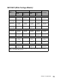
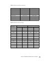
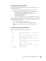
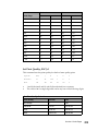
Table 3. Global Font and Size Parameters
Pitch
24 CPI Subscript (249X only)
20 CPI Subscript
17 CPI Normal
15 CPI Normal
12 CPI Normal
10 CPI Normal
8.5 CPI (17 CPI double-wide
7.5 CPI (15 CPI double-wide
6 CPI (12 CPI double-wide
5 CPI (10 CPI double-wide
Dec (Hs, Ls)
0 00 - 0 65
0 66 - 0 77
0 78 - 0 89
0 90 - 0 107
0 108 - 0 131
0 132 - 0 155
0 156 - 0 179
0 180 - 0 215
0 216 - 0 254
0 255 - 0 256
Hex (Hs, Ls)
00 00 - 00 41
00 42 - 00 4D
00 4E - 00 59
00 5A - 00 6B
00 6C - 00 83
00 84 - 00 9B
00 9C - 00 B3
00 B4 - 00 D7
00 D8 - 00 FF
01 00 - FF FF
Table 4. Global Font and Code Page
Code Page
Decimal
Hex
Hc
Lc
Hc
Lc
437
1
181
01H
B5H
850
3
82
03H
52H
860
3
92
03H
5CH
863
3
95
03H
5FH
865
3
97
03H
61H
437G
40
197
28H
C5H
813
3
45
03H
2DH
851
3
83
03H
53H
853T
42
101
2AH
65H
857
3
89
03H
59H
869
3
101
03H
65H
920
3
152
03H
98H
1053
4
29
04H
1DH
861
3
93
03H
5DH
1004
3
236
03H
ECH
858
3
90
03H
5AH
Section 3: IBM Emulation Mode Printer Commands
39
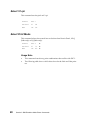
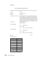
Select 12 cpi
This command sets the pitch at 12 cpi.
Format
ESC :
Decimal
27
58
Hex
1B
3A
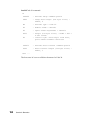
Select Print Mode
This command selects the normal font or the download font in Draft , NLQ
(248x only) or LQ (249x only).
Format
ESC I
n
Decimal
27
73
n
Hex
1B
49
n
Usage Note
•
•
40
This command cancels any print combinations that conflict with ESC I.
The following table shows valid values for n for the 248x and 249x printers:
Section 3: IBM Emulation Mode Printer Commands
248x
Dec
Hex
0
00
1
249x
Print Mode
Dec
Hex
Print Mode
Draft - Resident
0
00
Normal (Draft) 10 cpi
01
Fast DP (12 cpi) Resident
8
08
Normal (Draft) 12 cpi
2
02
NLQ Gothic Resident
16
10
Normal (Draft) 17 cpi
3
03
NLQ Courier Resident
2
02
Normal (LQ) 10 cpi Courier
4
04
Draft - Download
10
0A
Normal (LQ) 12 cpi Prestige
5
05
Fast DP (12 cpi) Download
18
12
Normal (LQ) 17 cpi Courier
6
06
NLQ - Download
3
03
Normal (LQ)
Porportional
7
07
NLQ - Download
4
04
Downloaded 10 cpi
Draft
8
08
Draft - Download
12
0C
Downloaded 12 cpi
Draft
9
09
Fast DP (12 cpi) Download
20
14
Downloaded 17 cpi
Draft
10
0A
NLQ Gothic Download
6
06
Downloaded 10 cpi
LQ
11
0B
NLQ Courier Italic Download
14
0E
Downloaded 12 cpi
LQ
12
0C
Draft - Download
22
16
Downloaded 17 cpi
LQ
13
0D
Fast DP (12 cpi) Download
7
07
Downloaded Porportional LQ
14
0E
NLQ - Download
15
0F
ALT NLQ II Download
Section 3: IBM Emulation Mode Printer Commands
41
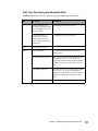
Select Print Type Style
This command is used for varying the type style of the character and the
number of line spacing. Use this printer command for:
•
•
•
•
•
•
•
•
•
Single-high character
Double-high character
Single-wide character
Double-wide character
Single line feed
Double line feed
Italic print (for 249x only)
Shadow (for 249x only)
Outline (for 249x only)
Format
ESC [
@
4
0
0
0
m3
m4
Decimal
27
91
64
4
0
0
0
m3
m4
Hex
1B
5B
40
04
00
0
00
m3
m4
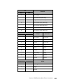
Usage Note
•
You may combine these selections; for example, italic print with doublehigh, double-wide character, and double line feed.
See the following table for m1, m3, and m4 selections.
42
Section 3: IBM Emulation Mode Printer Commands
m1
Selection
Dec
Hex
0
No Change
1
Start Italic Print (249x only)
2
Stop Italic Print (249x only)
4
Start Outline Print (249x only)
8
Stop Outline Print (249x only)
16
Start Shadow Print (249x only)
32
Stop Shadow Print (249x only)
m3
Height
Dec
Line Space
Hex
0
No Change
No Change
1
Single
No Change
2
Double
No Change
16
No Change
Single
17
Single
Single
18
Double
Single
32
No Change
Single
33
Single
Double
34
Double
Double
m4
Width
Dec
Hex
0
Unchanged
1
Single
2
Double
Section 3: IBM Emulation Mode Printer Commands
43
Emphasized (Bold) Print
Use this command for bold print.
To begin bold print:
Format
ESC E
Decimal
27
69
Hex
1B
45
To end bold print:
Format
ESC F
Decimal
27
70
Hex
1B
46
Double-Strike Print
Double-strike print results in a darker print because the printhead strikes the
character twice.
To begin double-strike print:
Format
ESC G
Decimal
27
71
Hex
1B
47
To end double-strike print:
44
Format
ESC H
Decimal
27
72
Hex
1B
48
Section 3: IBM Emulation Mode Printer Commands
Superscript or Subscript
To begin superscript:
Format
ESC S
n
Decimal
27
83
0
Hex
1B
53
00
To end superscript:
Format
ESC T
Decimal
27
84
Hex
1B
54
To begin subscript:
Format
ESC S
n
Decimal
27
83
1
Hex
1B
53
01
To end subscript:
Format
ESC T
Decimal
27
84
Hex
1B
54
Set Print Direction
This command sets the printer to print either unidirectionally or bidirectionally.
Format
ESC U
n
Decimal
27
85
n
Hex
1B
55
n
Usage Note
The value of n can be any of the following:
Decimal
Hex
Direction
0
00
bidirectional (both directions)
1
01
Unidirectional (left to right)
Section 3: IBM Emulation Mode Printer Commands
45
Continuous Double-wide Printing
This command selects or cancels a double-wide printing mode that is not
canceled by line feed terminators.
Format
ESC W
n
Decimal
27
87
n
Hex
1B
57
n
Usage Note
The value of n can be any of the following:
Decimal
Hex
Direction
0
00
Cancels double-wide printing mode
1
01
Sets double-wide printing mode.
Score Select
For 249x printers only.
This command selects several forms of overscore, underscore, and
strikethrough.
Format
ESC [
-
2
0
loc type
Decimal
27
91
45
2
0
loc type
Hex
1B
5B
2D
02
00
loc type
To select loc:
Underscore
Decimal
Hex
46
Strikethrough
Overscore
1
2
3
01
02
03
Section 3: IBM Emulation Mode Printer Commands
To select type:
Cancel
Decimal
Hex
Single
Double
0
1
2
00
01
02
Usage Note
To cancel this command, designate type as Dec 255 or Hex FF.
Continuous Underline
This command begins and ends continuous underline of spaces and characters.
To begin Continuous Underline:
Format
ESC -
n
Decimal
27
45
1
Hex
1B
2D
01
To end Continuous Underline:
Format
ESC -
n
Decimal
27
45
0
Hex
1B
2D
00
Continuous Overscore
This command prints a line above spaces and characters.
To begin Continuous Overscore:
Format
ESC _
n
Decimal
27
95
1
Hex
1B
5F
01
To end Continuous Overscore:
Format
ESC _
n
Decimal
27
95
0
Hex
1B
5F
00
Section 3: IBM Emulation Mode Printer Commands
47
Set Print Quality
This command sets the print quality to draft or letter quality.
Format
ESC [
Decimal
27
91
Hex
1B
5B
d
1
0
n
100
1
0
n
64 01
00
n
Usage Notes
•
•
48
For 2480 printers, the value of n can be any of the following:
Decimal
Hex
0
00
No Change
1 to 63
01 to 3F
Fast Draft
64 to 127
40 to 7F
Draft
128 to 254
80 to FE
Near Letter Quality
255
FF
Default Quality
For 2490 printers, the value of n can be any of the following:
Decimal
Hex
0
00
No Change
1 to 63
01 to 3F
Fast Draft
64 to 127
40 to 7F
Draft
128 to 191
80 to BF
Letter Quality
192 to 254
CO to FE
Enhanced Letter Quality
255
FF
Default Quality
Section 3: IBM Emulation Mode Printer Commands
Graphics Print Modes
Normal Density Bit Image Graphics
Use this command to print normal density bit images at 60 dots per inch (dpi)
horizontally and 72 dpi vertically.
Format
ESC K
Ln
Hn
data
Decimal
27
75
Ln
Hn
data
Hex
1B
4B
Ln
Hn
data
Usage Notes
•
•
Ln and Hn identify the number of bytes in data.
To print less than 256 bytes:
— Hn is 0.
— Ln is the number of bytes you want to print.
To print more than 256 bytes:
— Divide the number of bytes you want to print by 256.
— The result is Hn.
— The remainder is Ln.
data is the bit-mapped graphics information.
Each vertical dot column can have 8 rows of dots. To print bit image graphics,
the printer uses either the first 8 (248x) or 20 (249x) wires of the printhead to
map the eight bits of data. The following table shows how the print wires are
mapped for the 249x printer:
Bit Number
Binary Value
Print Wires
7
128
6
64
4, 5
5
32
6, 7
If dots 5 and 4 print, wire 8 is also used.
4
16
9, 10
3
8
1, 2
If dots 7 and 6 print, wire 3 is also used
11, 12
If dots 3 and 2 print, wire 13 is also used.
Section 3: IBM Emulation Mode Printer Commands
49
Bit Number
Binary Value
Print Wires
2
4
14, 15
1
2
16, 17
If dots 1 and 0 print, wire 18 is also used.
0
1
19, 20
Mode and Horizontal Density (249x Only)
For 249x printers only.
Use this command to select the mode and horizontal density for dot matrix
graphics.
Format
ESC [
g
Ln
Hn
mode
data
Decimal
27
91
103
Ln
Hn
mode
data
Hex
1B
5B
67
Ln
Hn
mode
data
Usage Notes
•
•
Ln and Hn identify the number of bytes in mode and data.
To print less than 256 bytes:
— Hn is 0.
— Ln is the number of bytes you want to print, plus 1 for the mode byte.
To print more than 256 bytes:
— Divide the number of bytes you want to print (plus 1 mode byte) by
256.
— The result is Hn.
— The remainder is Ln.
mode is the vertical wire count and the horizontal density in dots per inch.
Select mode from the following table.
Mode
50
Dec
Hex
0
00
60
8
1
01
120
8
2
02
120
8
3
03
240
8
Horizontal Density
Section 3: IBM Emulation Mode Printer Commands
Wires
Mode
•
Dec
Hex
8
08
60
24
9
09
120
24
11
0B
180
24
12
0C
360
24
13
0D
120
24
14
0E
180
24
16
10
360
48
Horizontal Density
Wires
data is the bit-mapped graphics information. The printhead moves at half
the speed of mode 2, giving better resolution.
Dual-Density Bit Image Graphics (Half Speed)
Use this command to print normal density bit images at 120 dpi horizontally
and 72 dpi vertically.
Format
ESC L
Ln
Hn
data
Decimal
27
76
Ln
Hn
data
Hex
1B
4C
Ln
Hn
data
Usage Notes
•
•
Ln and Hn identify the number of bytes in data.
To print less than 256 bytes:
— Hn is 0.
— Ln is the number of bytes you want to print.
To print more than 256 bytes:
— Divide the number of bytes you want to print by 256.
— The result is Hn.
— The remainder is Ln.
data is the bit-mapped graphics information.
Section 3: IBM Emulation Mode Printer Commands
51
Dual-Density Bit Image Graphics (Normal Speed)
Use this command to print dual-density bit images at 120 dpi horizontally and
72 dpi vertically.
Format
ESC Y
Ln
Hn
data
Decimal
27
89
Ln
Hn
data
Hex
1B
59
Ln
Hn
data
Usage Notes
•
•
Ln and Hn identify the number of bytes in data.
To print less than 256 bytes:
— Hn is 0.
— Ln is the number of bytes you want to print.
To print more than 256 bytes:
— Divide the number of bytes you want to print by 256.
— The result is Hn.
— The remainder is Ln.
data is the bit-mapped graphics information.
High-Density Bit Image Graphics
Use this command to print high-density bit images at 240 dpi horizontally and
72 dpi vertically.
Format
ESC Z
Ln
Hn
data
Decimal
27
90
Ln
Hn
data
Hex
1B
5A
Ln
Hn
data
Usage Notes
•
•
52
Ln and Hn identify the number of bytes in data.
To print less than 256 bytes:
— Hn is 0.
— Ln is the number of bytes you want to print.
To print more than 256 bytes:
— Divide the number of bytes you want to print by 256.
— The result is Hn.
— The remainder is Ln.
data is the bit-mapped graphics information.
Section 3: IBM Emulation Mode Printer Commands
Horizontal Movement
Set Horizontal Tabulation Stops
This command sets up to 28 tabulation stops to be used with the printer
command HT, Horizontal Tabulation.
Format
ESC D
tab stops
Decimal
27
680 n1.....n28
Hex
1B
44
0
0
n1.....n28 00
Usage Notes
n1.....n28 is used to set the tabulator stop positions.
•
•
•
•
•
•
ESC D is terminated by a 0 entry.
The first tabulation stop is at the leftmost column.
Input the tabulation stops (n1.....n28) in ascending numerical order.
ESC D 0 clears all existing horizontal tab stops.
The printer command ESC R resets to the default horizontal tabulation
stops, which are set at every eight positions beginning at column 9 (9, 17,
25, and so on).
The printer command HT, Horizontal Tabulation, activates the tabulation
stops set by this printer command.
Set Default Tabulation Stops
This command sets the tabulation stops to the default settings. The default
tabulation stops are set to every 8 columns, beginning at column 9 (9, 17, 25, and
so on).
Format
ESC R
Decimal
27
82
Hex
1B
52
Usage Notes
•
•
ESC R clears all vertical tabulation stops.
To set user-defined tabulation stops, use printer command ESC D.
Section 3: IBM Emulation Mode Printer Commands
53
Set Horizontal Margins
This command sets the left and right margins.
Format
ESC X
n1
n2
Decimal
27
88
n1
n2
Hex
1B
58
n1
n2
Usage Notes
•
•
•
•
Use n1 to select the left margin position.
Use n2 to select the right margin position.
Margins are specified in the character positions at the current pitchand are
stored in absolute displacement from the left edge of the paper.
The values for n1 and n2 must be between 0 and 255. If the value is set at 0,
the margin is left unchanged.
Move Current Print Position
This command moves the current print position to the right in increments of
1/120 inch.
Format
ESC d
increment
Decimal
27
100 Ln
Hn
Hex
1B
64
Hn
Ln
Usage Notes
To move less than 256 increments:
•
•
Hn is 0.
Ln is the increment you want to move.
To move more than 256 increments:
•
54
Divide the number of increments you want to move by 256.
— The result is Hn.
— The remainder is Ln.
Section 3: IBM Emulation Mode Printer Commands
Line Control
Automatic Line Feed (LF)
Executes an automatic line feed when a carriage return is received.
To begin automatic line feed (LF) on carriage return (CR):
Format
ESC 5
Begin
Decimal
27
53
1
Hex
1B
35
01
To end automatic line feed (LF) on carriage return (CR):
Format
ESC 5
End
Decimal
27
53
0
Hex
1B
35
00
Reverse Line Feed
Causes a reverse line feed; the paper is reversed according to the current line
spacing.
Format
ESC ]
Decimal
27
93
Hex
1B
5D
We do not recommend using this command.
Move Paper Vertically
Advances the paper in a vertical movement a distance of n/216 inches relative
to the current print position.
Format
ESC J
n
Decimal
27
74
n
Hex
1B
4A
n
Usage Notes
•
•
n is a value from 0 to 255 (decimal) or 0 to FF (hex).
n must be a multiple of 3 to advance exactly n/216 inch.
Section 3: IBM Emulation Mode Printer Commands
55
Set Vertical Units
For 249x printers only.
This command lets you set the size of the increments for the following
commands:
•
•
Set Line Spacing for Graphics (ESC 3)
Move Paper Vertically (ESC J).
Format
ESC [
\
4
0
0
0
m3
m4
Decimal
27
91
92
4
0
0
0
m3
m4
Hex
1B
5B
5C
04
00
00
00
m3
m4
Usage Notes
•
•
4 0 0 0 (decimal), 04 00 00 00 (hex) are constant digits.
m3 and m4 designate the denominator (the lower number) of a two-part
fraction. The fraction can be 1/180, 1/216, or 1/360, and indicates the fraction of an inch at which line feed spacing increments .
m3 (Hex)
m4 (Hex)
Denominator
D8H
00H
216
B4H
00H
180
68H
01H
360
Vertical Tabulation
Set Vertical Tabulation Stops
Sets as many as 64 tabulation stops by line number.
Format
ESC B
tab settings
0
Decimal
27
66
n1.....n64
0
Hex
1B
42
n1.....n64
00
Usage Notes
•
56
Use ESC B to set the tabulation stops and to advance paper to the next vertical tabulation stop (VT) to activate them.
Section 3: IBM Emulation Mode Printer Commands
•
•
•
ESC R (Set Default Tabulation Stops) and ESC B 0 will clear all vertical tab
stops.
Set the tabulation stops in ascending order (n1.....n64).
The last digit in the sequence must be a 0 to terminate the command.
Line Spacing
Set Line Spacing to 1/8 Inch
This command (ESC zero) sets the line spacing at 1/8 inch between each line,
which is 8 lines per inch (lpi).
Format
ESC 0
Decimal
27
48
Hex
1B
30
Set Line Spacing to 7/72 Inch
This command sets the line spacing at 7/72 inch between each line, which
is 10.3 lpi.
Format
ESC 1
Decimal
27
49
Hex
1B
31
Activate Line Spacing for Text
This command activates the line spacing designated by the Set Line Spacing for
Text (ESC A) printer command.
Format
ESC 2
Decimal
27
50
Hex
1B
32
Section 3: IBM Emulation Mode Printer Commands
57
Set Line Spacing for Text
This command sets line spacing in n/72 inch increments. To activate the line
spacing, use the printer command Activate Line Spacing for Text (ESC 2).
Format
ESC A
n
Decimal
27
65
n
Hex
1B
41
n
Usage Note
The value for n must be between 1 and 85.
Set Line Spacing for Graphics
This command sets line spacing to n/216 inches. It does not cause the form to
move. It changes the vertical distance moved when a line feed command is
received.
Format
ESC 3
n
Decimal
27
51
n
Hex
1B
33
n
Usage Notes
•
•
The number can be from 0 to 255 (decimal), 00 to FF (hexadecimal).
n must be a multiple of 3 to advance exactly n/216 inches.
Porportional Space Mode
This command turns porportional space mode on and off.
Format
ESC P
n
Decimal
27
80
n
Hex
1B
50
n
Usage Notes
•
•
58
Porportional spacing is ON when n is set to 0 (decimal) or 00 (hexadecimal).
Porportional spacing is OFFwhen n is set to 1 (decimal) or 01 (hexadecimal).
Section 3: IBM Emulation Mode Printer Commands
Set Top of Form and Page Length
Set Top of Form
This command sets the first line of printing on each page to the current paper
position.
Format
ESC 4
Decimal
27
52
Hex
1B
34
Set Page Length in Inches
This command sets the page length to a specified number of inches.
Format
ESC C
0
inches
Decimal
27
67
0
n
Hex
1B
43
00
n
Usage Notes
•
•
•
The value of n is the number of inches you want to set as the page length
and must be between 1 and 255.
When the command is sent, the current vertical position becomes the new
top of form.
If the printer command Set Skip Perforation (ESC N) is active, or if "skip
over perforation" is On in the printer setup, this printer command deactivates it.
Set Page Length in Lines
This command sets the page length to a specified number of lines.
Format
ESC C
lines
Decimal
27
67
n
Hex
1B
43
n
Usage Notes
•
The value of n is the number of lines you want to set as the page length and
works in conjunction with the current line spacing (ESC A).
Section 3: IBM Emulation Mode Printer Commands
59
•
•
When the command is sent, the current vertical position becomes the new
top of form.
If the printer command Set Skip Perforation (ESC N) is active, or if "skip
over perforation" is On in the printer setup, this printer command deactivates it.
Set Skip Perforation
This command specifies the number of lines to be skipped at the bottom of each
page, which creates a bottom margin.
Format
ESC N
lines
Decimal
27
78
n
Hex
1B
4E
n
Usage Notes
•
•
•
This command remains in effect until:
— Cancel Skip Perforation (ESC O) printer command is received.
— Set Page Length in Lines (ESC C) printer command is received.
— Set Page Length in Inches (ESC C 0) printer command is received.
Valid values for n are 1 through 255 (decimal), 01 through FF
(hexadecimal).
To cancel this printer command, use Cancel Skip Perforation (ESC O).
Cancel Skip Perforation
This command cancels Set Skip Perforation (ESC N).
60
Format
ESC O
Decimal
27
79
Hex
1B
4F
Section 3: IBM Emulation Mode Printer Commands
Printer Control
Deselect Printer
When this command is sent, the printer ignores all data except DC1 .
Format
ESC Q
n
Decimal
27
81
n
Hex
1B
51
n
The following values of n are valid:
Model
Dec
Hex
Mode
Setting
3
03
ON
182
B6
OFF
22
16
ON
184
B8
OFF
2480
2481
23H
2490
B9H
24H
2491
B7H
Setup Barcode Parameter
This command sets the barcode parameters to the printer.
Format
ESC [
f
6
0
k
m
s
v1
v2
c
Decimal
27
91
102 6
0
k
m
s
v1
v2
c
Hex
1B
5B
66
k
m
s
v1
v2
c
06
00
Usage Note
The printer must receive this command prior to the barcode data command.
Section 3: IBM Emulation Mode Printer Commands
61
The barcode type is denoted by k. The following values are valid for k:
k
Barcode Type
Dec
Hex
177
B1
<reserved>
178
B2
EAN-13
179
B3
EAN-8
180
B4
CODE 39
181
B5
<reserved>
182
B6
INTERLEAVED 2 of 5
183
B7
UPC-A
184
B8
<reserved>
185
B9
POST-NET (barcode)
186
BA
CODE 128
Module width is denoted by m. When m is 1, the barcode prints by
1/360 or 1/240 full dot method. For all other values, the barcode prints by half
dot method. The suggested values for m are as follows:
m
Dec
Hex
0
Unit Module
Dots
Width
24 wire
9 wire
00
0.015 in.
0.021 in.
1
01
0.012 in.
0.017 in.
2
02
0.015 in.
0.021 in.
3
03
0.021 in.
0.030 in.
4
04
0.026 in.
0.038 in.
The variable s denotes the space width adjustment and affects the barcode
printing width. The value for s may range from 3 (03 hex) to -3 (FD hex),
however, 0 is the default value. The adjustment unit for 24 wire printers is
1=1/360 in. and for 9 wire printers the unit is 1=1/240 in.
The variables v1 and v2 control the bar length. The minimum value of v1, v2 is
288 dec (24 wire) and 270 (9 wire).
62
Section 3: IBM Emulation Mode Printer Commands
The variable c denotes the control code. The control is made up of 8 bits
(b1 - b8). The 8 bits are defined as follows:
b1
Check Digit
b2
Human Readable Character (0: print On, 1: print Off)
b3
EAN-13, UPC-A flag character position (0: Center, 1: Under)
b4 -b8 Not used
Setup Barcode Data
This command sets the barcode data on the current printing position. .
Format
ESC [
p
n1
n2
d1
d2
Decimal
27
91
112 n1
n2
d1
d2
Hex
1B
5B
70
n2
d1
d2
n1
Usage Notes
•
•
The printer must receive the ESC [ f command prior to the ESC [ p command.
The barcode prints after the printer receives the LF line feed command.
Command length is denoted by n1 and n2. The following values are valid for
n1 and n2 when the automatic check digit generation flag is on and when it is
off:
Automatic Check Digit Generation Flag Off
n1 (low byte)
n2(high byte)
Barcode Type
Dec
Hex
Dec
Hex
13
0D
0
00
EAN-13
8
08
0
00
EAN-8
1 to 255
01 to FF
0
00
CODE 39
1 to 255
01 to FF
0
00
INTERLEAVED 2 of 5
12
0C
0
00
UPC-A
10
0A
0
00
POST-NET (barcode)
2 to 255
02 to FF
0
00
CODE 128
Section 3: IBM Emulation Mode Printer Commands
63
Automatic Check Digit Generation Flag On
n1 (low byte)
n2(high byte)
Barcode Type
64
Dec
Hex
Dec
Hex
12
0C
0
00
EAN-13
7
07
0
00
EAN-8
1 to 255
01 to FF
0
00
CODE 39
1 to 255
01 to FF
0
00
INTERLEAVED 2 of 5
11
0B
0
00
UPC-A
9
09
0
00
POST-NET (barcode)
2 to 255
02 to FF
0
00
CODE 128
Section 3: IBM Emulation Mode Printer Commands
Epson Emulation
Mode Printer
Commands
Section
4
This section provides tables describing Epson mode commands you can use
with your printer.
Font Selection
Name
Dec
Hex
Description
ESC %
27 37 n
1B 25 n
Select User-defined Set
n=0 Selects the resident set.
n=1 Selects the user-defined set.
ESC ( - 27 40 45 3 0 1 d1 d2 1B 28 2D 03 00 01 d1 d2 Select Score (249x only)
d1=1 Underline
d1=2 Strike-through
d1=3 Overscore
d2=0 Cancel d1 selection
d2=1 Single continuous line
d2=2 Double continuous line
d2=5 Single broken line
d2=6 Double broken line
ESC I
27 73 n
1B 49 n
Printable Code Area Expansion
(248x only)
n=1 Allows non-printable codes
to be used for user-defined
characters.
n=0 Cancels n=1 selection.
Section 4: Epson Emulation Mode Printer Commands
65
Name
Dec
Hex
Description
ESC R
27 82 n
1B 52 n
Select an International
Character Set
n=0 USA
n=1 France
n=2 Germany
n=3 U.K.
n=4 Denmark 1
n=5 Sweden
n=6 Italy
n=7 Spain 1
n=8 Japan
n=9 Norway
n=10 Denmark 2
n=11 Spain 2
n=12 Latin America
n=13 Korea (249x only)
n=64 Legal (249x only)
66
Section 4: Epson Emulation Mode Printer Commands
Name
Dec
Hex
Description
ESC k
27 107 n
1B 6B n
248x: Select Near-LetterQuality Font
Selects the font to be used in
NLQ mode.
n=0 Courier
n=1 Gothic
249x: Select Letter-Quality Font
Selects the font to be used in LQ
mode.
n=0
n=1
n=2
n=3
n=4
n=5
n=6
n=7
n=8
ESC q
27 113 n
1B 71 n
Prestige
Gothic
Courier
Prestige
Script
Gothic
Gothic
Orator
Presentor
Select Character Style
(249x only)
n=0 Normal
n=1 Outline
n=2 Shadow
n=3 Outline with shadow
ESC t
27 116 n
1B 74 n
Select Character Tables
Selects italic or character graphics
as the extended character.
n=0 Italics Character table
n=1 Epson Extended Graphics
table
n=2 User-defined Character table
(249x only)
ESC x
27 120 n
1B 78 n
248x: Select Near Letter Quality
or Draft
n=0 Selects Draft mode
n=1 Selects NLQ mode
249x: Select Letter Quality or
Draft
n=0 Selects Draft mode
n=1 Selects LQ mode
Section 4: Epson Emulation Mode Printer Commands
67
Name
Dec
Hex
ESC (t
27 40 116 3 0 d1 d2 d3 1B 28 74 3 0 d1 d2 d3
Description
Assign Character Tables
Parameter range
0 ≤ d1 ≤ 1, 48 ≤ d1 ≤ 50
0 ≤ d2 ≤ 255
d3 = 0, 16
Function
Assigns the d2 and d3 registered
character table to the d1 character
table according to the following
values (the d1 character table is
one of the four tables selectable
with the ESC t command):
68
Section 4: Epson Emulation Mode Printer Commands
d2
d3
Table/Code Page
0
1
1
2
3
3
4
4
5
5
6
7
8
9
11
15
24
0
0
16
16
0
16
0
16
0
16
16
0
0
0
0
0
0
Italic table
Graphic table/437
Graphic table/437G
Graphic table/813
Graphic table/850
Graphic table/858
Graphic table/851
Graphic table/920
Graphic table/853T
Graphic table/1053
Graphic table/1004
Graphic table/860
Graphic table/863
Graphic table/865
Graphic table/857
Graphic table/869
Graphic table/861
Text Print Mode
Name
Dec
Hex
Description
ESC M
27 77
1B 4D
Print 12 Characters per Inch
ESC P
27 80
1B 50
Print 10 Charaters per Inch
ESC SP
27 32 n
1B 20 n
Set Variable Character Spacing
Sets additional space to the right of each
character, which is added to the original
space alloted to the character cell, n/120
inch. n can be a value of 0 to 127.
ESC !
27 33 n
1B 21 n
Select Print Style
Selects the print style as indicated in the
n parameter. See the table on page 70 for
the print styles available.
DC2
18
12
Cancel Condensed Mode
ESC 4
27 52
1B 34
Start Italic Printing
ESC 5
27 53
1B 35
Stop Italic Printing
ESC –
27 45 n
1B 2D n
Begin or End Continuous Underline
n=0 End
n=1 Begin
ESC E
27 69
1B 45
Begin Emphasized Printing
ESC F
27 70
1B 46
End Emphasized Printing
ESC G
27 71
1B 47
Begin Double-Strike Printing
ESC H
27 72
1B 48
End Double-Strike Print
ESC p
27 112 n
1B 70 n
Proportional Spacing Mode
n=0 End
n=1 Begin
ESC S
27 83 n
1B 53 n
Begin Superscript or Subscript
n=0 Superscript
n=1 Subrscript
ESC T
27 84
1B 54
End Superscript or Subscript
Section 4: Epson Emulation Mode Printer Commands
69
Name
Dec
Hex
Description
ESC a
27 97 n
1B 61 n
Select Justification
n=0 prints the line of characters against
the left margin.
n=1 centers the line of characters
between the left and right margins.
n=2 prints the line of characters against
the right margin.
n=3 causes lines of characters to be
printed evenly along both the left
and right edges when the buffer
becomes full.
ESC w
27 119 n
1B 77 n
Begin or End Double-high Printing
n=0 End
n=1 Begin
DEL
127
7F
Delete Text
Deletes the text character at the end of a
print line.
The following table lists the n parameters for the ESC ! command.
70
n=
On
Off
Dec
Hex
Print Style
0
No
Yes
0
00
10 cpi
Yes
No
1
01
12 cpi
1
Yes
No
2
02
Proportional
2
Yes
No
4
04
Condensed
3
Yes
No
8
08
Emphasized
4
Yes
No
16
10
Double-Strike
5
Yes
No
32
20
Double-Wide
6
Yes
No
64
40
Italic
7
Yes
No
128
80
Underscore
Section 4: Epson Emulation Mode Printer Commands
Graphics Print Modes
Name
Dec
Hex
Description
ESC ^
27 94 m Ln 1B 5E m Ln 9-Pin Graphics Mode (248x only)
Hn data
Hn data
Prints 9-pin bit-image graphics.
m=0 Normal density (60 dpi)
m=1 Dual density (120 dpi)
m=2 High speed dual density (120 dpi)
m=3 Quadruple density (240 dpi)
ESC ?
27 63 n1 n2 1B 3F n1 n2 Change Graphics Mode Command
Changes the graphic mode assigned to a graphics
mode command.
n1=K Normal density
n1=L Dual density
n1=Y High speed, dual density
n1=Z Quadruple density
n2
0, 1, 2, 3, 4, 6, 7, 32, 33, 38, 39, and 40
(Decimal)
Selects the graphic mode number to be assigned to
the graphics mode command specified by the
ESC * command. See the ESC * command on page
72.
ESC K
27 75 Ln
Hn data
1B 4B Ln Hn Normal Density Bit Image Graphics
data
Prints normal density bit images at 60 dpi
horizontally and 72 dpi vertically.
ESC L
27 76 Ln
Hn data
1B 4C Ln Hn Dual Density Bit Image Graphics
data
Prints normal density bit images at 120 dpi
horizontally and 72 dpi vertically.
ESC Y
27 89 Ln
Hn data
1B 59 Ln Hn Dual Density Bit Image Graphics (HighSpeed)
data
Prints dual density bit images at 120 dpi
horizontally and 72 dpi vertically.
ESC Z
27 90 Ln
Hn data
1B 5A Ln Hn Quadruple Density Bit Image Graphics
data
Prints high density bit images at 240 dpi
horizontally and 72 dpi vertically.
Section 4: Epson Emulation Mode Printer Commands
71
Name
Dec
Hex
Description
ESC *
27 42 n Ln 1B 2A n Ln Set Graphics Mode
Hn data
Hn data
Prints bit-image graphics in the mode specified
by n.
See the following tables for modes that can be
specified by parameter n.
248x Graphic Modes that can be specified by parameter n in the ESC *
command:
n=
Density
0
Normal
1
Dots per Inch
(dpi)
Equivalent Command
60
ESC K
Dual
120
ESC L
2
Dual (High speed)
120
ESC Y
3
Quadruple
240
ESC Z
4
CRT-I Screen
80
None
5
Plotter (1:1)
72
None
6
CRT-II Screen
90
None
7
Dual Plotter
144
None
249x Graphic Modes include 0, 1, 2, 3, 4 and 6 from the 248x table above and the
following additional values of n in the ESC * command:
72
Dots per Inch
(dpi)
Equivalent Command
n=
Density
32
High resolution for ESC K
60
None
33
High resolution for ESC L
120
None
38
CRT-III Screen
90
None
39
High resolution, triple
density
180
None
40
High resolution, hex
density
360
None
Section 4: Epson Emulation Mode Printer Commands
Horizontal Movement
Name
Dec
Hex
Description
BS
8
08
Backspace
Moves left one space, based on pitch setting.
HT
9
09
Horizontal Tab
Moves right to the next horizontal tab stop. Tab is
set with the ESC D command.
ESC D
27 68 0 n1 1B 44 0 n1,
n2...n32 0 n2...n32 00
ESC $
27 36 n1 n2 1B 24 n1 n2 Set Absolute Print Position
Offsets the print position by an absolute distance
from the left margin. The formula for calculating
offset is: (n1 + (n2 x 256))/60 (inch).
CR
13
0D
Carriage Return
Moves print position horizontally to the left
margin.
SP
32
20
Space
Moves print position one print column to the right.
ESC I
27 108 n
1B 6C n
Set Left Margin
Sets the left margin in character positions at the
current pitch.
Left margin=n (character) x cpi
ESC Q
27 81 n
1B 51 n
Set Right Margin
Sets the right margin in character positions at the
current pitch.
ESC \
27 92 n1 n2 1B 5C n1 n2 Set Relative Position
Offsets the print position by the relative distance
from the current position.
Offset=(n1 + (n2 x 256))/120 (inch).
Set Horizontal Tab Stops
Sets up to 32 tabs by column number (n1...n32) in
ascending order. The sequence ends with 0.
Section 4: Epson Emulation Mode Printer Commands
73
Vertical Movement
Name
Dec
Hex
Description
LF
10
0A
Line Feed
Advances the form one line.
VT
11
0B
Vertical Tab
Advances the paper to the next vertical tab stop.
ESC B
27 66 0 n1 1B 42 0 n1,
n2...n16 0 n2...n16 00
Set Vertical Tab Stops
Sets up to 16 tab stops. The sequence ends with 0.
FF
12
0C
Form Feed
Advances the paper to the top of the next page.
ESC J
27 74 n
1B 4A n
Relative Move Base Line
Advances the paper by n/216 inches on 248x
printer; n/180 inches on 249x printer.
ESC j
27 106 n
1B 6A n
Reverse Relative Move Base Line
Feeds the paper by n/216 inches in the reverse
direction on 248x printer; n/180 inches in the
reverse direction on 249x printer.
ESC b
27 98 m
n1...n8 0
1B 62 m
n1...n8 00
Set Vertical Tabs in Channel
Sets vertical tab stops in specified channel by m.
m must be a one-byte decimal value from 0 to 7.
ESC Q
27 81 n
1B 51 n
Set Right Margin
Sets the right margin in character positions at the
current pitch.
ESC /
27 47 n
1B 2F n
Select Vertical Tab Channel
Line Spacing
74
Name
Dec
Hex
Description
ESC +
27 43
1B 2B
Set n/360 Line Spacing - 249x only
ESC 0
27 48
1B 30
Set 1/8 Inch Line Spacing
Sets line spacing to eight lines per inch.
ESC 1
27 49
1B 31
Set 7/72 Inch Line Spacing - 248x only
Sets line spacing to 7/72 lines per inch.
ESC 2
27 50
1B 32
6 Lines Per Inch
Sets line spacing to six lines per inch.
Section 4: Epson Emulation Mode Printer Commands
Name
Dec
Hex
Description
ESC 3
27 51 n
1B 33 n
Set Graphics Line Spacing - 248x only
Use a line spacing of 24/216 for bit-image graphics
using 8 bits. n must be a 1-byte decimal value from
0 to 255. To move exactly n/216 inch per line, n
must be an integer multiple of 3.
Set Graphics Line Spacing - 249x only
Sets line spacing to n/180 inches per line.
ESC A
27 65
1B 41
Set n/72 Inch Line Spacing
Sets line spacing to n/72 inch for subsequent line
feed command. The value of n must be between 0
and 85.
ESC b
27 98 m
n1...n16 0
1B 62 m
n1...n8 00
Set Vertical Tabs in Channel
Sets vertical tab stops in specified channel by m.
m must be a one-byte decimal value from 0 to 7.
Page Format
Name
Dec
Hex
Description
ESC C 0
27 67 0 m
1B 43 00 m
Set Page Length to m Inches
ESC C
27 67 n
1B 43 n
Set Page Length to n Lines
ESC N
27 78 n
1B 4E n
Set Skip Perforation
Creates a bottom margin by skipping n lines. Valid
values of n are 0 through 255.
ESC O
27 79
1B 4F
Cancel Skip Perforation
Cancels the skip perforation function.
Printer Control
Name
Dec
Hex
Description
ESC s
27 115
1B 73
Turn Half Speed Mode On/Off -248x only
ESC EM
27 25 n
1B 19 n
Auto Sheet Feeder On/Off
n=0 Off
n=4 On
n=R Eject
ESC B
27 66 0 n1 1B 42 0 n1,
n2...n16 0 n2...n16 00
Set Vertical Tab Stops
Sets up to 16 tab stops. The sequence ends with 0.
FF
12
Form Feed
Advances the paper to the top of the next page.
0C
Section 4: Epson Emulation Mode Printer Commands
75
Name
Dec
Hex
Description
BEL
7
07
Beeper
Sounds the printer beeper for approximately 1
second.
DC1
17
11
Select Printer (XON)
The host sends this command to signal the printer
to begin printing data.
DC3
19
13
Null (XOFF)
CAN
24
18
Cancel Data
Clears data received since the last buffer
terminator.
NUL
0
00
Null
ESC U
27 85 n
1B 55 n
Set Print Direction
n=0 bidirectional
n=1 unidirectional
ESC @
27 64
1B 40
Initialize Printer
Clears all data stored in the printer buffer.
ESC [K
27 91 75
1B 5B 4B
Set Initial Condition
Resets the printer to its original state. (This
command is the same as ESC [K command in IBM
mode. See page 32.)
ESC K
27 91 75
1B 5B 4B
String Descriptor Download Command
Resets the printer to user default settings after
downloading the string descriptor to the printer.
(This command is the same as ESC K command in
IBM mode. See page 32.)
Other Commands
76
Name
Dec
Hex
Description
ESC 6
27 54
1B 36
Printable Code Area Expansion
ESC 7
27 55
1B 37
Cancel Printable Code Area Expansion
ESC 8
27 56
1B 38
Disable Paper-out Sensor (248x only)
Turns off the paper-out sensor to allow printing to
the end of a paper.
ESC 9
27 56
1B 38
Disable Paper-out Sensor (248x only)
Cancels ESC 8.
ESC #
27 35
1B 23
Disable Control of MSB
Disables the control of the MSB value set by ESC =
or ESC >.
Section 4: Epson Emulation Mode Printer Commands
Name
Dec
Hex
Description
ESC &
27 38 0 n1 1B 26 0 n1
n2 d1 data n2 d1 data
Define Download Characers
ESC :
27 58 0 n 0 1B 3A 00 n
00
Copy Normal Characters from ROM to RAM
ESC <
27 60
1B 3C
Select Left-to-Right Printing
ESC =
27 61
1B 3D
Set MSBs to Zero
Sets the MSBs of all data sent to the printer to 0.
ESC >
27 62
1B 3E
Set MSBs to One
Sets the MSBs of all data sent to the printer to 1.
ESC W
27 87 n
1B 57 n
Begin or End Continuous Double-Wide Printing
n=0 End
n=1 Begin
ESC [f
27 91 102
1B 5B 66
Setup Barcode Parameter
This command is the same as the ESC [f command
in the IBM mode. (See page 32.)
ESC [f
27 91 112
1B 5B 70
Setup Barcode Data
This command is the same as the ESC [p command
in the IBM mode. (See page 32.)
SI
15
0F
Start 17 cpi printing
SO
14
0E
Begin Double-Wide Printing by Line
ESC SO
27 14
1B 0E
Select Double-Wide
ESC SI
27 15
1B 0F
Select Condensed Mode
DC2
18
12
Cancel Condensed Mode
DC4
20
14
End Double-Wide Printing by Line
ESC :
27 58
1B 3A
Set 12 Pitch Font
Section 4: Epson Emulation Mode Printer Commands
77
78
Section 4: Epson Emulation Mode Printer Commands
OKI Microline
Emulation Mode
Printer Commands
Section
5
This section provides tables describing OKI Microline mode commands you
can use with your printer.
Character Set
Name
Dec
Hex
Description
ESC ! 0 27 33 48
1B 21 30
Select Standard Character Set
ESC ! 1 27 33 49
1B 21 31
Select Block Graphics Character
Set
ESC ! 2 27 33 50
1B 21 31
Select Line Character Set
ESC ! n 27 33 n
1B 21 n
Select an International
Character Set
Character Set
n
Dec
64
65
66
70
72
68
74
67
73
76
71
90
75
69
Hex
40
41
42
46
48
44
4A
43
49
4C
47
5A
4B
45
USA
USA 2
British
Danish
Dutch
French
Fr. Canadian
German
Italian
Latin Am.
Norway
Publisher
Spaini
Swedish
Section 5: OKI Microline Emulation Mode Printer Commands
79
Name
Dec
ESC [ T 27 91 84 Ln Hn 0 0
Hcp Lcp 0
Hex
Description
1B 5B 54 Ln Hn 0 0 Hcp
Lcp 04
Print from Code Page
If printing less than 256
characters:
Ln = # characters to be printed
H n= 0
If printing more than 256
characters, divide the total
number of characters by 256:
Ln = whole number of quotient
Hn= remainder of quotient
Hcp Lcp
1
2
3
3
3
4
4
Code Page Set
Decimal
181 USA
82 Multilingual
92 Canadian French
95 Portugal
97 Norway
16 BRASCII
17 Abicomp
Hcp Lcp Code Page Set
Hexadecimal
01
B5 USA
02
52 Multilingual
03
5C Canadian French
03
5F Portugal
03
61 Norway
04
10 BRASCII
04
11 Abicomp
80
Section 5: OKI Microline Emulation Mode Printer Commands
Character Size and Spacing
Name
Dec
Hex
Description
RS
30
1E
Print 10 Characters per Inch
FS
28
1C
Print 12 Charaters per Inch
ESC g
27 103
1B 67
Print 15 Charaters per Inch
GS
29
1D
Print 17.1 Charaters per Inch
ESC # 3
27 35 51
1B 23 33
Print 20 Charaters per Inch
ESC J
27 74
1B 4A
Start Superscript Printing
ESC K
27 75
1B 4B
Stop Superscript Printing
ESC L
27 76
1B 4C
Start Subscript Printing
ESC M
27 77
1B 4D
Stop Subscript Printing
ESC US
31
1F
Begin Double-Width Printing
ESC US 1
27 31 49
1B 1F 31
Begin Double-Height Printing
ESC US 0
27 31 48
1B 1F 30
End Double-Height Printing
ESC &
27 38 n1 n2 1B 26 n1 n2 Select Print Features
n3 n4 58
n3 n4 3A
Selects print quality, character pitch and
other print features. See the Table 1 on
page 82 for the features applicable to
each variable and the value of each. To
calculate the total value of a variable,
add the values (column 1) of each
feature you want to use, and then add
that sum to the variable factor (bottom
row).
Note: You may enter any combination of
the variables (n1 to n4) in any order.
ESC Y
27 89
1B 59
Select Porportional Spacing
Adjusts the space between letters to
compensate for the varying widths of
individual characters.
Note: Available only with Near Letter
Quality (NLQ) and Draft printing.
ESC Z
27 90
1B 5A
Cancel Porportional Spacing
ESC N
27 78 n
1B 4E n
Select Intercharacter Spacing
Adds additional spacing to the right of
each character. Valid values for n must
be between 0 and 11.
Section 5: OKI Microline Emulation Mode Printer Commands
81
Table 1. Variable Values and Factors for Combined Print Features Command
Value
n1
1
10 cpi
2
4
8
12 cpi
17.1 cpi
20 cpi
16
Double Width
Factor
32
Variable/Feature
n2
n3
Cancel super/ Utility
subscripts
Subscripts
NLQ
Superscripts
DLL
Emphasized
Italics
(Bold)
Enhanced
N/A
64
n4
HSD
N/A
Underlining
Double Height
N/A
96
112
Character Style
82
Name
Dec
Hex
Description
ESC # 0
27 35 48
1B 23 30
Select Fast Draft Print Mode
ESC 0
27 48
1B 30
Select Draft Print Mode
ESC 1
27 49
1B 31
Select NLQ Font
ESC 3
27 51
1B 33
Select Near Letter Quality Gothic Font
ESC ! /
27 33 42
1B 21 2A
Select Italics Printing
ESC ! *
27 33 47
1B 21 2F
Cancel Italics Printing
ESC T
27 84
1B 54
Select Emphasized (Bold) Printing
ESC H
27 72
1B 48
Select Enhanced Printing
ESC I
27 73
1B 49
Cancel Emphasized (Bold)/Enhanced Printing
ESC C
27 67
1B 43
Select Underline Printing
ESC D
27 68
1B 44
Cancel Underline Printing
Section 5: OKI Microline Emulation Mode Printer Commands
Custom Characters
Name
Dec
Hex
Description
ESC $
27 36
1B 24
Copy ROM Character Set to RAM Character Set
Copies a complete set of the characters resident in
the printer to the area of its memory reserved for
custom characters.
ESC % A
27 37 65 m 1B 25 41 m
n1...n11
n1...n11
Down Line Load Ascender Characters
Begins downloading an ascender character.
ESC % D
27 37 68 m 1B 25 44 m
n1...n11
n1...n11
Down Line Load Descender Characters
Begins downloading an descender character.
ESC 2
27 50
1B 32
Set DLL in Draft Mode
Switches custom character printing on when the
printer is set for the Draft print mode.
ESC 7
27 55
1B 37
Select DLL NLQ mode
Switches custom character printing on when the
printer is set for the NLQ print mode.
Graphics Print Modes
Name
Dec
Hex
Description
ESC P
27 80
1B 50
Single Density Graphics
ESC Q
27 81
1B 51
Single Density Graphics
ESC R
27 82
1B 52
Double Density Graphics
ESC # Q
27 35 81
1B 23 51
Double Speed and Quadruple Density Graphics
ESC *
27 42 n1 n2 1B 2A n1 n2 Select Graphics Mode
58
3A
Selects the density and defines the speed and
"word size." For more information, see Table 2 and
Table 3 on page 84.
ETX
3
03
Select Graphics Print Mode
ETX STX
32
03 02
Cancel Graphics Print Mode
ETX LF
3 10
03 0A
Graphics Line Feed with Carriage Return (Text)
ETX SO
3 14
03 0E
Graphics Line Feed with Carriage Return
(Graphics)
ETX DC2
3 18
03 12
Graphics Line Feed without Carriage Return
(Text)
ETX DC4
3 20
03 14
Graphics Line Feed without Carriage Return
(Graphics)
Section 5: OKI Microline Emulation Mode Printer Commands
83
Name
Dec
Hex
Description
ETX ETX
33
03 03
Stored graphics data in one dot column buffer
Determines the graphics setting. In 7-bit mode, the
graphic setting is 14/144"; in 8-bit graphics mode,
it is 16/144"
Table 2. Density
n1
Dots per inch/Density
1
60 dpi
2
72 dpi
4
Single density
8
Double density
16
Quadruple density
To calculate the density (value for n1),
1 Locate the dpi and density you want from the above table.
2 Select the corresponding n1 values for each.
3 Add the values selected in step 2.
4 Add 96 to the total.
Example: For 60 dpi printing at quadruple density, calculate the value of n1 as
follows: n1=1+16+96=113
Table 3. Speed and Word Size
n2
Speed/Word Size
0
Normal speed
8
Double speed
0
7-bit graphics
16
8-bit graphics
To calculate the speed and word size (value for n2),
1 Locate the speed you want from the above table.
2 Select the corresponding n2 value.
3 Locate the word size (7 or 8-bit graphics).
4 Select the corresponding n2 value.
84
Section 5: OKI Microline Emulation Mode Printer Commands
5 Add the values selected in steps 2 and 4.
6 Add 64 to the total.
Example: For double speed, 8-bit graphics, calculate the value of n2 as follows:
n2=8+16+64=88
Horizontal Movement
Name
Dec
Hex
Description
BS
8
08
Backspace
CR
13
0D
Carriage Return.
ESC % C
27 37 67 n1 1B 25 43 n1, Set Left Margin
n2 n3
n2, n3
If the value for the left margin is less than 3 digits,
use zeros for the first digit(s). Maximum margin
value is 899 (2480 printer model) or 999 (2481
printer model). Units are set at 1/120".
ESC % R
27 37 82 n1 1B 25 52 n1 Set Right Margin
n2 n3 n4 n2 n3 n4
The right margin must be at least 60 units greater
than the left margin. If the value for the right
margin is less than 4 digits, use zeros for the first
digit(s). Maximum margin value is 0960 (2480
printer model) or 1632 (2481 printer model). Units
are set at 1/120".
ESC HT
9
09
Execute Horizontal Tab
Advances the printhead 8 columns to the right
before printing the next character.
ESC HT ... 27 9 x1 y1 1B 09 x1 y1 Set Horizontal Tabs by Characters
CR
z1...x16 y16 z1...x16 y16 Sets tab stops for up to 16 positions. The values for
z16 0D
x, y and z must be entered as three-digit ASCII
z16 13
numbers (use leading zeros if necessary),
separated by commas, and in ascending order.
Maximum values are as follows:
Pitch
2480
2481
10 cpi
080
136
12 cpi
096
163
15 cpi
120
204
17.1 cpi
137
233
20 cpi
160
272
Section 5: OKI Microline Emulation Mode Printer Commands
85
Name
Dec
ESC ETX ... 27 3 x1 y1
CR
z1 w1...x16
y16 z16
w16 13
Hex
Description
1B 03 x1 y1
z1 w1...x16
y16 z16 w16
0D
Set Horizontal Tabs by Dot Columns
Sets tab stops for up to 16 positions. The character
pitch determines the distance represented by the
tab (distance from the center of one dot to the
center of the next dot).
Pitch
Shift Increment
10 cpi
1/120
12 cpi
1/144
15 cpi
1/180
17.1 cpi
1/206
20 cpi
1/240
The values for x, y, z and w must be entered as
four-digit ASCII numbers (use leading zeros if
necessary), separated by commas, and in
ascending order.
To calculate the value, multiply the position for
which you want to set a tab by the pitch increment
of shift, and then subtract one from the product.
For example, to set a tab for 2" from the left margin
using 12 cpi pitch, multiply 2 by 144, and then
subtract 1. The value would be 0287.
Maximum values are as follows:
Pitch
2480
2481
10 cpi
959
1631
12 cpi
1151
1956
15 cpi
1339
2447
17.1 cpi
1643
2795
20 cpi
1917
3261
86
ESC HT
CR
27 9 13
1B 09 0D
ESC % B
27 37 66 n1 1B 25 42 n1 Indent from Left Margin
n2 n3 n4 n2 n3 n4
See the command ESC ETX ... CR on page 86 for
instructions on calculating the value for n1...n4.
(Use the same pitch increment of shift values as the
ESC ETX ... CR command.)
ESC HT CR
Clears horizontal tabs set by character spacing.
Section 5: OKI Microline Emulation Mode Printer Commands
Name
Dec
Hex
Description
ESC DLE @ 27 16 64 pN 1B 10 40 pN Set Multiple Print Positions
a1 a2 p1 p2 a1 a2 p1 p2 Moves the print position to the right or left, as an
p3 p4
p3 p4
absolute or relative print position.
pN=0 to 127
a1=0 (absolute print position)
a1=1 (relative print position)
a2=0 (move to the left (backward))
a2=1 (move to the right (forward))
The character pitch determines the distance
represented by the tab (distance from the center of
one dot to the center of the next dot).
Pitch
Shift Increment
10 cpi
1/120
12 cpi
1/144
15 cpi
1/360
17.1 cpi
1/411
20 cpi
1/480
The values for p1, p2, p3 and p4 must be entered as
four-digit ASCII numbers (use leading zeros if
necessary), separated by commas, and in
ascending order.
To calculate the value, multiply the position for
which you want to set a tab by the pitch increment
of shift, and then subtract one from the product.
For example, to set a tab for 2" from the left margin
using 12 cpi pitch, multiply 2 by 144, and then
subtract 1. The value would be 0287.
Maximum values are as follows:
Pitch
2480
2481
10 cpi
959
1631
12 cpi
1151
1956
15 cpi
1339
2447
17.1 cpi
1643
2795
20 cpi
1917
3261
ESC % F
27 37 70 n1 1B 25 46 n1 Move to the Left
n2 n3 n4 n2 n3 n4
See the command ESC ETX ... CR on page 86 for
instructions on calculating the value for n1...n4.
(Use the same pitch increment of shift values as the
ESC ETX ... CR command.)
ESC % E
27 37 69 n1 1B 25 45 n1 Move to the Right
n2 n3 n4 n2 n3 n4
See the command ESC ETX ... CR on page 86 for
instructions on calculating the value for n1...n4.
(Use the same pitch increment of shift values as the
ESC ETX ... CR command.)
ESC -
27 45
1B 2D
Begin Uni-directional Printing
ESC =
27 61
1B 3D
End Uni-directional Printing
Section 5: OKI Microline Emulation Mode Printer Commands
87
Vertical Movement
Name
Dec
Hex
Description
ESC G
27 71 Hn Ln 1B 47 Hn Ln Set Page Length in Inches
Sets the page length in increments of 1/2" x the
values of Hn Ln.
The values for Hn and Ln should be between 00
and 99. For lengths less than 4.5", Hn = 0.
ESC F
27 70 Hn Ln 1B 46 Hn Ln Set Page Length in Lines
Sets the page length in increments of
line pitch x the values of Hn Ln.
The values for Hn and Ln should be between 00
and 99. For values less than 10, Hn = 0.
ESC % S 1 27 37 83 49 1B 25 53 31 Select Skip Over Perforation
Skips an inch from the bottom of one page to the
top of the next.
ESC % S 0 27 37 83 48 1B 25 53 30 Cancel Skip Over Perforation
FF
12
0C
Form Feed (with carriage return)
Advances the paper to the top of the next page.
LF
10
0A
Line Feed (with carriage return)
Advances the form one line.
ESC DC2
27 18
1B 12
Graphics Line Feed (without carriage return)
Advances the form one line without returning to
the left margin. Allows you to overstrike a line of
printing and to create special effects like double
underlines.
ESC ? n :
27 63 n 58 1B 3F n 3A
Carriage Return/Feed Selection
Value of n
33
ESC % 5 n 27 37 53 n 1B 25 35 n
88
Operation
Carriage return only
34
Forward line feed, no carriage return
35
Forward line feed w/carriage return
48
Reverse line feed, no carriage return
49
Reverse line feed w/carriage return
Perform n/144" Line Feed
0 < n < 127
ESC VT
27 11 Hn Ln 1B 0B Hn Ln Skip Down Select Number of Lines
ESC LF
27 10
1B 0A
Reverse Line Feed
ESC 6
27 54
1B 36
Set Line Spacing to 1/6"
ESC 8
27 56
1B 38
Set Line Spacing to 1/8"
ESC % 9
27 37 57 n 1B 25 39 n
Set Line Spacing to n/144"
Section 5: OKI Microline Emulation Mode Printer Commands
Name
Dec
Hex
Description
20 32...32 14 20...20 n... Set Vertical Format Unit (VFU)
DC4
SP...SP n... n... 32...32 20...20 n... 3F Programs up to 12 sets (channels) of vertical tabs.
The maximum tab stops in one set (channel) is 27.
SP...SP n...? n... 63
This command works in conjunction with the VT
command followed by a channel code (n). When
the VT command is received, the printer skips to
the next tab stop in that channel.
To set your tabs, follow the DC4 code with one SP
code for each line to be skipped in order to
advance to the line where you want your first tab
stop. For example, the command
DC4 32 32 32 5 32 12 32 32 20 32 32 32 32....32 63
causes the printer to skip 3 lines, enters a tab stop
at 5, skips 1 line, enters a tab stop at 12, skips 2
lines, enters a tab stop at 20, and then skips
however many lines remain on the page.
VT
11 n
0B n
Vertical Tab
Advances the paper to the next vertical tab stop.
Valid channel codes are 49 through 60.
ESC 5
27 53
1B 35
Set Top of Form
Other Commands
Name
Dec
Hex
Description
CAN
24
18
Cancel Data
Clears all data from the print buffer, but does not
reset printing features.
ESC {
27 123 n
1B 7B n
Change Emulation
When n=2 the emulation changes to IBM
Proprinter.
When n=65 the emulation changes to Epson.
ESC CAN 27 24
1B 18
Initialize Printer
Clears all data from the print buffer, and returns
the printer to the current menu settings.
ESC <
27 60
1B 3C
Select Half-speed Printing
ESC >
27 62
1B 3E
Cancels Half-speed Printing
ESC E 0
27 69 0
1B 45 00
Select Paper-out Sensor
ESC E 1
27 69 1
1B 45 01
Cancel Paper-out Sensor
DC3
19
13
Select Print Suppress Mode
DC1
17
11
Cancel Print Suppress Mode
1B 7D 00
Software-Prime
ESC { NUL 27 125 0
Section 5: OKI Microline Emulation Mode Printer Commands
89
90
Name
Dec
Hex
Description
ESC V
27 86
1B 56
Eject Page
Section 5: OKI Microline Emulation Mode Printer Commands
Using the
Printer Interface
Section
6
The printer interface is the physical connection point between the printer and
other devices, such as a computer. The 2400 series printer offers a choice of
three printer interfaces: parallel, Universal Serial Bus (USB), or serial.
Use the parallel interface and parallel cable if you are attaching the printer to a
personal computer’s parallel port.
Use the USB interface and USB cable when you are attaching the printer to a
personal computer’s USB port.
Use the serial interface and serial cable when you:
•
•
share the printer using a printer sharing device.
need to connect the printer to a computer that does not have a parallel
port, or to a computer that does not have an available parallel port.
Parallel Interface
Use Lexmark parallel cable 1329605 (3 m or 10 ft.) or 1427498 (6.1 m or 20 ft.).
The parallel cable must be IEEE 1284-compliant and must support two-way
(bidirectional) communications printing
The parallel interface sends 8 bits (one byte) of data at one time and is
transistor-transistor logic (TTL) compatible.
Parallel Interface Voltage Levels
The maximum voltage level for control or data lines is +5.2 volts.
A control or data line is:
•
•
High, if the voltage is greater than +2.4 volts.
Low, if the voltage is less than +0.8 volts.
Section 6: Using the Printer Interface
91
Computer to Printer Communication
The parallel interface transfers data from computer to printer. The data path is 8
bits wide. The printer and the computer synchronize data transfer with the
interface signals STROBE*, ACKNLG*, and BUSY.
When the computer is ready to send a byte of data to the printer, the computer
puts the byte of data on the data lines. Then the computer sends a STROBE*
(low) pulse to the printer. The printer responds with a BUSY (high) signal.
After the printer receives the data, the printer pulses the ACKNLG* (low) line.
This signals the computer that the printer has read the byte of data into printer
memory. If the printer buffers are not full and the printer can receive more data,
the printer removes the BUSY (low) signal.
92
Section 6: Using the Printer Interface
Pin Connections
The following illustration shows the pin assignments for connecting the 25-pin
connector to the 36-pin connector.
Lexmark Parallel Cables
P/N 1329605 (10 ft.)
P/N 1427498 (20 ft.)
Printer
Computer
Shield
STROBE
DATA 0
DATA 1
DATA 2
DATA 3
DATA 4
DATA 5
DATA 6
DATA 7
ACKNLG*
BUSY
PE
SLCT
AUTO FEED
ERROR*
INIT*
SLCTIN*
1
2
3
4
5
6
7
8
9
10
11
12
13
14
15
16
17
GROUND
GROUND
18
19
GROUND
20
GROUND
21
GROUND
22
GROUND
23
GROUND
24
GROUND
25
1
2
3
4
5
6
7
8
9
10
11
12
13
14
15
16
17
18
19
20
21
22
23
24
25
26
27
28
29
30
31
32
33
36
STROBE
DATA 0
DATA 1
DATA 2
DATA 3
DATA 4
DATA 5
DATA 6
DATA 7
ACKNLG*
BUSY
PE
SLCT
AUTO FEED
N/C
0 VOLTS
N/C
N/C
GROUND
GROUND
GROUND
GROUND
GROUND
GROUND
GROUND
GROUND
GROUND
GROUND
GROUND
GROUND
INIT*
ERROR
GROUND
SLCTIN*
Shield
Lexmark compliant cables are supported up to 20 feet.
Section 6: Using the Printer Interface
93
Parallel Pin Assignments
Pin
Line
Description
1
STROBE*
When the printer receives the STROBE* low from the
computer, the printer reads the data from the interface and
sets the BUSY line high. STROBE* must not occur when the
BUSY line is high; otherwise, unpredictable results may occur.
2-9
DATA
These signals are the 8 bits of parallel data sent from the
computer. A high level indicates a logical 1. A low level
indicates a logical 0. The printer reads data from the DATA
lines when a STROBE* pulse is received.
10
ACKNLG*
The ACKNLG* pulse tells the computer that the data from the
previous STROBE* pulse has been read. An ACKNLG* pulse
is also generated when the printer is turned on, or at the
completion of the printer initialization by an INIT* requested
from the computer.
11
BUSY
When the printer sets BUSY high, it cannot receive data. The
BUSY line goes high in response to a STROBE* pulse. This line
remains high until the data is read. BUSY is also high when:
• The receive buffer is full.
• An out-of-paper condition occurs.
• The printer receives an INIT* signal.
• Start/Stop is pressed to go offline.
• A printer error condition has occurred.
• The printer is initializing.
12
PE
The printer sets Paper End (PE) high when approximately
12.7 mm (0.5 in.) of paper remains in the printer. PE remains
high until the operator loads paper and presses Start/Stop.
13
SLCT
When the printer is ready, it sets the SLCT line high.
The SCLT lines go low when:
• Start/Stop is pressed to go offline.
• There is an error or out-of-paper condition.
• The printer receives an ESC Q. It ignores all incoming data
except DC1, which returns the printer to a select state.
14
AUTO
FEED XT
The printer executes one line feed when this signal, valid only
in Epson** mode, is low.
15
Not used.
16
GND
Logic ground.
17
CHASSIS
GROUND
Ground level.
18
+5 volts
Maximum 300 mA.
19-30
GND
Ground level.
* Inverted logic (signal is active when low).
94
Section 6: Using the Printer Interface
Pin
Line
Description
31
INIT*
INIT* from the system resets the printer to its initial poweron-state. The BUSY line goes high, and any received data is
printed. When INIT* goes low, the printer resets to the poweron default state. If data is in the USB buffer, the USB FIFO is
not reset.
32
ERROR*
The printer sets the ERROR* line low if the printer detects an
error or out-of-paper condition.
A critical error condition exists when both ERROR* and PE
are low.
33
GND
Ground level.
34-35
36
Not used.
SELECT IN
The printer does not respond to the DC1/DC3 code when this
signal, valid only in Epson mode, is low.
* Inverted logic (signal is active when low).
Timing
The following chart shows the timing in microseconds of these signals.
Section 6: Using the Printer Interface
95
Universal Serial Bus Interface
The USB interface, with a signaling bit rate of 12 Mb/s (full speed), is in full
compliance with the Universal Serial Bus Specification Revision 1.0. It has a
USB Function Controller with two FIFO-based Endpoints:
•
•
One bidirectional Control Endpoint 0 (8 bytes)
One receive Endpoint 1 (1*64 bytes)
Serial Interface
You may want to use the serial interface when you need to use a cable more
than 6 m (20 ft.) in length, share the printer using a printer sharing device, if you
need to connect the printer to a computer that does not have a parallel port, or
to a computer that does not have an available parallel port.
Use the RS-232C protocol if the printer is more than 6 m (20 ft.) from the
computer.
Serial Interface Option
The Lexmark serial interface, part number 12T0154, supports the RS-232C
protocol. All serial interface parameters can be selected by the operator panel.
The serial interface installs internally into the back of the printer, and connects
to the serial cable, part number 1038693.
How to Connect the RS-232C Serial Interface
To connect the serial interface, use the following cable:
•
96
Lexmark Part Number 1038693 (15.24 m or 50 ft.)
Section 6: Using the Printer Interface
Serial Cable Pin Assignments (RS-232C)
The following illustration shows the RS-232C serial cable:
25-Pin
Male
13
25
1
14
25-Pin
D-shell
Female
25
14
Serial Adapter Side
13
1
Computer Side
RS-232C Serial Connector Pin Assignments
Pin
Signal
Description
2
TXD
(Transmit Data)
This line transmits data from the printer to the host. The data
characteristics are specified by the function menu settings which are
read only during a Power On Reset (POR). The only data
transmitted are XON (x’11’) and XOFF (x’13’) signals. Transmission
occurs only when CTS is high.
3
RXD
(Receive Data)
This line receives data from the host. The serial interface accepts
data only when DSR is On.
4
RTS
(Request to Send)
This line is set high and remains high even after the serial interface
finishes its POR.
5
CTS
(Clear to Send)
This line is monitored only if the XON/XOFF protocol is selected
because transmission occurs only when CTS is high.
6
DSR
(Data Set Ready)
DSR is another method of providing data integrity. Data is accepted
only when DSR is high.
20
DTR
(Data Terminal Ready)
This line is set high after the serial interface finishes its POR
sequence. However, if you select DTR pacing handshake protocol,
this line is used to indicate to the host whether or not the printer is
ready to receive any more data.
Section 6: Using the Printer Interface
97
Serial Interface Cable (RS-232C)
The recommended RS-232C serial cable is 50 feet long. This cable works with
the IBM PS/2 series and other compatible host systems using a 25-pin male
connector. The maximum total capacitance of the cable and the connector
should be less than 2500 pF, or it will delay the signal transition by more than
4%.
Following is a diagram of the serial cable (Lexmark part number 1038693 (15.24
m or 50 ft.)).
98
Section 6: Using the Printer Interface
Using an IBM AT Personal Computer (RS-232C)
If you are using an IBM AT or compatible computer, use a 9-pin to 25-pin EIA
RS-232C cable.
We recommend one of the following for a 9-pin to 25-pin cable:
•
•
IBM P/N 6450242 (254 mm or 10 in.)
IBM P/N 6450217 (3 m or 10 ft.)
The following illustration shows the pin assignments for the 9-pin to 25-pin
RS-232C serial cable.
IBM 9-Pin to 25-Pin Adapters
6450242 (254 mm or 10 in.)
6450217 (30.4 m or 10 ft.)
Lexmark Null Modem Serial Cable
1038693 (15.24 m or 50 ft.)
Shield
DCD
RXD
TXD
DTR
GND
DSR
RTS
CTS
1
2
3
4
5
6
7
8
RI
9
9 (F)
Shield
1
2
3
4
5
6
7
8
20
22
25 (M)
TXD
RXD
RTS
CTS
DSR
GND
DCD
DTR
F. GND
1
2
3
4
5
6
7
2
3
4
5
6
7
8
20
TXD
RXD
RTS
CTS
DSR
L. GND
20 DTR
25 (M)
25 (F)
Serial Communication Parameters (RS-232C)
The acceptable values for serial communications parameters follow.
Voltage Level Range
The maximum voltage level range for control lines or data lines is from
± 25 positive V dc to ± 25 negative V dc.
Section 6: Using the Printer Interface
99
The voltage reference point is the signal ground on pin 7. A timing or control
line is active if the voltage is more than +3 V, or inactive if the voltage is less
than -3 V.
A data signal more than +3 V means that the bit is a logical 0; less than -3 V
means that the bit is a logical 1.
For additional information, refer to the Interface between Data Terminal Equipment
and Data Communications Equipment Employing Serial Binary Data Interchange,
published by the Electronic Industries Association, publications EIA RS-232C
and EIA\TIA-232-E.
Serial Data Frame Considerations (RS-232C)
The computer sends serial data in data frames (also known as packets). You can
create 10-bit, 11-bit, or 12-bit data frames and set the serial data transfer
parameter so that each data frame contains 7 or 8 data bits. However, the
printer is an 8-bit printer; characters, controls, and APA graphics need 8 bits of
data. If you select 7-bit data transfer, some unexpected characters might print.
Data Transmission
Data transfer rates (in bits per second):
•
•
•
•
•
•
•
300 bps
600 bps
1200 bps
2400 bps
4800 bps
9600 bps
19200 bps
Start and Stop Bits
The printer receives data with 1 start bit and either 1 or 2 stop bits. The printer
always sends 1 start and 2 stop bits.
Parity
There are four possible parity settings: Even, Odd, No, and Ignore.
When Even parity is selected, the printer expects to receive data frames with an
even number of logical 1’s per byte. The printer transmits data with even parity.
When Odd parity is selected, the printer expects to receive data frames with an
odd number of logical 1’s per byte. The printer transmits data with odd parity.
100
Section 6: Using the Printer Interface
When No parity is selected, the pritner expects no parity bit when it receives
data. The printer transmits data without parity bits.
When Ignore parity is selected, the printer expects a parity bit when it receives a
data frame. Although the printer expects a parity bit, it ignores the bit and does
not check for a parity error condition. The printer uses even parity when it
transmits data.
Errors
The serial interface recognizes the following three error conditions: Parity Error,
Framing Error, and Buffer Overrun.
When a parity error is detected, the interface prints an upside down question
mark. Although the printer continues to receive data, it prints an upside down
question mark for each byte that has a parity error.
A framing error is similar to a parity error. When a framing error is detected, the
interface also prints an upside down question mark and continues to receive
data. However, unlike a parity error which causes the interface to print question
marks only for the bytes with incorrect parity, a framing error causes the
interface to print question marks for all bytes transmitted.
A buffer overrun error occurs when the host does not obey the selected protocol
and continues to send data even after the buffer is full. The buffer can only hold
128 bytes of data after the printer signals that it is busy. If the host sends more
than this amount, the data is lost and a buffer overrun error occurs.
Data Flow Control
Flow control is accomplished by way of software or the hardware DTR (Data
Terminal Ready). Three flow control protocols are available:
•
•
•
DTR Pacing (hardware)
XON/XOFF (software)
Multi XON/XOFF (software)
DTR Protocol Timing
You use DTR to control the data flow from the computer. DTR goes from high to
low to indicate to the computer that the printer cannot receive more data due to
one of the following conditions:
•
•
•
Buffer full
Attendance error (paper out, printer error)
Printer not in ready state
Section 6: Using the Printer Interface
101
The following diagram illustrates DTR Protocol Timing.
Legend:
1
The RTS signal is driven directly by the RS-232C line driver and is active
any time power is supplied to the printer.
2
The DTR signal becomes active (high) when initialization is complete,
telling the computer that the printer is ready to receive data.
3
DTR drops (low) to tell the computer that the printer buffer is full or the
printer is busy and data transmission should stop. If the computer continues to send data after the printer lowers the DTR signal, data could be
lost. DTR is raised (high) when the printer is again ready to receive data.
XON/XOFF Protocol Timing
When you select this flow control protocol, the printer sends an XOFF
command to the host to indicate that the printer cannot receive more data
because it has one of the following conditions:
•
•
•
Buffer full
Attendance error (paper out, printer error)
Printer is not in ready state
The following diagram illustrates XON/XOFF Protocol Timing.
Legend:
1
102
Data received when DSR is low is invalid and discarded.
Section 6: Using the Printer Interface
2
Because all data transmissions require CTS, it must be detected prior to
the XON/XOFF protocol initiating. Once CTS is detected, after POR, the
printer transmits an XON command. It is not necessary for the host to
detect this initial XON command prior to transmitting data to the
printer.
3
The printer transmits an XOFF command to the host when the receive
buffer is full.
4
The printer transmits an XON command to the host when buffer space
becomes available and the printer is ready to receive more data.
Serial Computer Configuration Recommendations (RS-232C)
For the correct operation of the serial adapter, you must configure the operating
system of the computer. The following examples show how to configure DOS
and OS/2 for the printer using serial DTR protocol.
DOS
From the DOS prompt, enter the following commands:
mode com1:9600,n,8,1
Include this command statement in the AUTOEXEC.BAT file on the computer
so it runs each time your system starts operating.
OS/2 1.2 and 1.3
1
2
3
4
5
From Desktop Manager or Group Utilities, select Utilities.
Select Control Panel.
Select Options.
Select Communications Port.
For the port you wish to set up, set the following parameters to match
the printer defaults.
Baud rate = 9600
Word length = 8
Parity = none
Stop bits =1
Handshake = hardware
6
Select Set.
OS/2 2.0 and 2.1
Make sure the OS/2 serial port settings match the switch settings on the serial
adapter. To view or to change the settings:
Section 6: Using the Printer Interface
103
1
2
3
4
Select the printer icon.
5
6
Select the settings you want to use.
Select Open.
Select Settings. The Printer - Settings screen appears.
Select the serial port to which you want to attach the printer. The Serial
Port - Settings screen appears.
Select OK.
The next example shows an alternative way to configure OS/2.
From the OS/2 prompt, enter the following command:
mode com1:9600,n,8,1,,DTR=on,OCTS=on,ODSR=on
You can also include the following command statement in the CONFIG.SYS file
on your computer so that it runs each time you start your computer:
run c:\os2\mode.com com1:,,,,,DTR=on,OCTS=on,ODSR=on
104
Section 6: Using the Printer Interface
Downloading
Characters and
Fonts
Section
7
This chapter explains how to download characters and provides programming
examples for several escape sequences. The first part of the chapter is for 248x
users; the second part is for 249x users.
The downloading feature lets you create custom fonts and special characters.
You can create and print complete italic or foreign language character sets as
well as symbols and special characters not in the printer character sets.
The examples in this chapter use the BASIC programming format shown on
page 16.
248x Printers
Designing Draft and NLQ Characters
For Draft and NLQ (Near-Letter Quality) characters, the 9-wire printers use a
character matrix that is 12-dots wide and 9-dots high. Ascenders generally use
the top 7 rows, establishing row 7 as the baseline. Descender characters
generally use the bottom 7 rows. For uniform and evenly spaced characters,
each character should be 9-dots wide and start in column 1.
How Dots Are Added in NLQ Mode
The 9-wire printers can print downloaded draft characters in NLQ mode.
Downloaded characters print at the same speed as standard characters. You
design the characters for Draft and the printer adds the additional dots to each
character when printing in NLQ mode.
Section 7: Downloading Characters and Fonts
105
Vertical Lines
The following drawing shows how the printer adds dots to a vertical line.
Columns
1 2 3 4 5 6 7 8 9 10 11
Rows
1
2
3
4
5
6
7
8
9
The solid dots must be specified in the font. Hollow dots are generated by the
printer.
Diagonal Lines
These drawings show how the printer adds dots to diagonal lines.
Columns
1 2 3 4 5 6 7 8 9 10 11
106
Columns
1 2 3 4 5 6 7 8 9 10 11
Rows
1
Rows
1
2
2
3
3
4
4
5
5
6
6
7
7
8
8
9
9
Section 7: Downloading Characters and Fonts
Intersections of Vertical and Horizontal Lines
The drawing on the left shows how the printer adds the vertical dots to a
vertical line that intersects a horizontal line.
The character design must specify all dots in the horizontal line. The printer
removes adjacent dots from horizontal lines when printing in Draft, which is
illustrated in the drawing on the right.
Columns
1 2 3 4 5 6 7 8 9 10 11
Columns
1 2 3 4 5 6 7 8 9 10 11
Rows
1
Rows
1
2
2
3
3
4
4
5
5
6
6
7
7
8
8
9
9
Section 7: Downloading Characters and Fonts
107
Diagonal Intersecting Horizontal Line
This drawing shows how the printer adds dots at the intersection of horizontal
and diagonal lines. The printer considers the point of intersection as a two-dot
vertical line.
Columns
1 2 3 4 5 6 7 8 9 10 11
Rows
1
2
3
4
5
6
7
8
9
Diagonal Intersecting Vertical Line
The ’M’ shows how the printer adds dots when a diagonal line meets the end of
a vertical line.
Columns
1 2 3 4 5 6 7 8 9 10 11
108
Columns
1 2 3 4 5 6 7 8 9 10 11
Rows
1
Rows
1
2
2
3
3
4
4
5
5
6
6
7
7
8
8
9
9
Section 7: Downloading Characters and Fonts
When a diagonal line intersects a vertical line at a point other than the end of the
vertical line, you should specify a horizontal dot at the intersection to improve
character appearance. This ensures that the character is acceptable in Draft.
Designing Fast Draft Characters
The character matrix for Fast Draft characters is 10-dots wide and 9-dots high.
Ascender characters generally use the top 7 rows, establishing row 7 as the
baseline. Descender characters use the bottom 7 rows. Fast Draft characters
must be no wider than 9 dots, or they will be truncated when printed. Fast Draft
characters cannot be printed in NLQ mode.
Designing NLQ II Characters
NLQ II characters are designed on a character matrix 24-dots wide and 18-dots
high. Ascenders generally use the top 15 rows, establishing row 15 as the
baseline.
Descenders use the bottom 16 rows (rows 3 through 18). The maximum
character width is 23 dots. The maximum height of a character is 16 dots,
beginning with row 1 (for ascenders) or row 3 (for descenders). If you design a
character that is higher than 16 dots, it will be truncated when printed.
Consecutive horizontal dots are eliminated (except in emphasized mode) when
characters are printed. To ensure a character looks the same when printed left to
right or right to left, the number of consecutive dots in a character design should
be odd.
To design characters that will blend with the resident characters, use rows 2
through 15 when designing a capital letter. If you are designing a lowercase
letter such as ’a’, ’c’, or ’e’, use rows 6 through 15. For lowercase ascenders such
as ’b’, ’d’, or ’f’, use rows 1 through 15. For lowercase descenders such as ’g’, ’p’,
or ’q’, use rows 6 through 18.
Downloading Characters
The 9-wire printers have 3 download areas. The first download area is for a
draft character set and can store 256 characters in any area of the character set.
The draft download area can also be used to store a downloaded Fast Draft
character. The other two download areas are for NLQ II+. Any type of character
can be downloaded using the ESC = command and selected for printing with
the ESC I command.
If you use the operator panel to select a code page from Character Options the
draft download area is initialized to code page 437. The two NLQ II download
areas are also unitized to code page 437 Courier and italic fonts.
Section 7: Downloading Characters and Fonts
109
Initializing the Download Area
Use the following command to initialize the download areas to the resident
fonts:
<x
1B3D
-
download command prefix
0000
-
byte count when zero causes initialization of
download area
>
Downloading a Draft/NLQ Character Set
The sequence to download characters for Draft/NLQ and Fast Draft is shown
below:
Syntax:
ESC
=
count1 count2 font id start
Decimal:
27
61
count1 count2 20
start
Hex:
1B
3D
count1 count2 14
start
There are two parts of the ESC = escape sequence.
Part one includes count 1, count 2, font ID byte, and the start code. Use this
part once for each download command.
Part two is made up of one or more sequences of 13 bytes of data. The first two
bytes of data are the 2 attribute bytes, and the remaining 11 bytes (3 through 13)
are printable data. Repeat this part (2 attribute bytes plus 11 printable bytes) for
each character you download:
attr1 attr2 col1 col2 col3 ... col11
Part One: Calculating Count 1, Count 2
Count 1, count 2
Font ID byte
Start
110
is a two-byte integer value, starting with the low order
byte followed by the high order byte.
is 20 (x14) for the Draft/NLQ font.
The start code specifies the first download character. The
download characters replace normal characters starting
at that code point.
For example, to download a character set that replaces
characters starting with the uppercase letter ’A’, use a
start code of 65 (x41).
Section 7: Downloading Characters and Fonts
Part Two: Specifying the Download Data
Attribute byte 1 specifies the character type and additional information.
Bit
Bit Values
Functions
7
0 if the character is an
Ignored if bit 0 or bit 1 is set to 1.
ascender (a character using
only the upper 8 wires of
the print head).
1 if the character is a
Ignored if bit 0 or bit 1 is set to 1.
descender, a character
using only the lower 8
wires of the print head (for
example, g).
6-2
Not used; set to zeros.
1, 0
0,0 no expansion.
Normal ascender/descender character
based on bit 7.
0,1 line-drawing character.
The dots in row 8 are extended downward
through rows 9, 10, 11, and 12. Bit 7 is
ignored. Use this mode to create characters
similar to resident font characters 179 to
223.
1,0 shading character.
The dots in rows 1, 2, 3, and 4 are repeated
as rows 9, 10, 11, and 12. NLQ mode is
ignored. Use this mode to create characters
similar to resident font characters 176 to
178.
1,1 not valid.
Section 7: Downloading Characters and Fonts
111
Attribute byte 2 specifies proportional-spacing information. Bits 6-0 specify
spacing information. Set these bits to 0 if proportional spacing is not desired.
When you use proportional spacing with a downloaded font that has bits 6-0 set
to 0, all 11 bytes of character data print.
Bit
Bit Values
Functions
7
Set to 0.
6, 5, 4
Interpreted as a binary
number.
Specifies the number of leading dot
columns to ignore. This number is the
offset. Up to 7 dot columns can be ignored.
3, 2, 1, 0
Interpreted as a binary
number.
Specifies the number of dot columns to be
printed. Each character is automatically
followed by a blank column that is not
included in the character width. Widths
greater than 11 will be treated as 11.
Printable
Data
(Bytes 3
through
13)
Define the printable data.
These bytes are unique to each character,
and must be specified for each download
character. The printer prints one byte at a
time. Each wire in the printhead has a
corresponding bit in each byte, depending
on whether the character is an ascender or a
descender. To print the dot, set the bit to 1.
See the following illustration.
Bit
Bit
7
Not Used
6
7
5
6
4
5
3
4
2
3
1
2
0
1
Not Used
0
Ascenders
112
Section 7: Downloading Characters and Fonts
Descenders
Designing and Downloading the Draft/NLQ Copyright (©)
Symbol
This example shows how the 11 bytes of printable data for the ’©’ symbol were
determined.
Columns
1 2 3 4 5 6 7 8 9 10 11
Rows
1
Bits
7
2
6
3
5
4
4
5
3
6
2
7
1
8
0
9
Decimal
Values- 56 68 0 146 170 170 170 130 0 68 56
Hexadecimal
Values- 38 44 00 92 AA AA AA 82 00 44 38
This example replaces the ’@’ character with the Draft ’©’ symbol. This character
is an ascender without proportional spacing. Count 1 and count 2 for the
example are:
total count = (1 x 13) + 2 = 15
count 1 = x0F
count 2 = x00
Section 7: Downloading Characters and Fonts
113
The following example loads data for the copyright symbol into the printer. The
data remains in the download storage area until you:
•
•
•
Set the power switch to Off.
Overlay the data with download character data.
Download area is initialized.
<x
1B3D
-
download command prefix
0F00
-
byte count (low byte first)
14
-
font ID for Draft/NLQ
40
-
start code - ’@’ character
00
-
attribute byte 1 - ascender - no 12 high
expansion
00
-
attribute byte 2 - default proportional
space data
38
-
column 1
44
-
column 2
00
-
column 3
92
-
column 4
AA
-
column 5
AA
-
column 6
AA
-
column 7
82
-
column 8
00
-
column 9
44
-
column 10
38
-
column 11
1B4904
-
select download font
40
-
print ’@’ character
>
114
Section 7: Downloading Characters and Fonts
Downloading an NLQ II Character Set
The 248x printers can download two sets of NLQ II characters. The first set is
initialized to a Courier-like font, and the second to a Courier italic-like font.
Since there are two download areas, you must use a Select Print Mode, ESC I,
before downloading to select between the two download areas. To select the
first area, use the ESC I x07 command. For the second download area, use the
ESC I x0F command.
Downloading NLQ II character set is performed using the ESC = command
similar to the Draft/NLQ download command.
Syntax:
ESC
=
count1 count2 font id start
Decimal:
27
61
count1 count2 21
start
Hex:
1B
3D
count1 count2 15
start
Part One: Calculating Count 1, Count 2
Count 1, count 2
Font ID byte
Start
specify the number of bytes to be downloaded.
is the value assigned to identify the type of font data. The
ID for NLQ II is 21 (x15).
The start code is the ASCII value (code-point) for the first
downloaded character. It must be in the range of x00 to
xFF. You can start your downloaded character set at any
point in the character table. The download characters
replace normal characters starting at this code-point. For
example, to download a character set that replaces characters starting with the uppercase letter ’A’, use a start
code- point equal to 65 (x41), ’A’. All character codes
within the same download command must be consecutive from the start code-point.
Section 7: Downloading Characters and Fonts
115
Part Two: Specifying the Download Data
Each font character is made up of 48 bytes of data. There are 2 bytes of attribute
data and 46 bytes of character data. This field of 48 bytes must be repeated for
each character. The following text describes the specifications of the attribute
bytes and the character data.
Attribute byte 1 specifies the character type.
Bit
Bit Values
Functions
7
0 if the character is an
Ignored if bit 0 or bit 1 is set to 1.
ascender.
1 if the character is a
descender
(for example, ’g’).
6-2
Currently ignored and
should always be zero.
1,0
0,0 no 12-high expansion.
Ignored if bit 0 or bit 1 is set to 1.
Bit 7 is valid.
0,1 line-drawing character.
Expand the bottom row 15
down to rows 17, 19, 21,
and 23. Expand the bottom
row 16 down to rows 18,
20, 22, and 24. The
ascender/descender bit 7
above is ignored.
1,0 shading character.
Expand the top dots in
rows 1, 3, 5, and 7 down to
rows 17, 19, 21, and 23.
Expand the top dots in
rows 2, 4, 6, and 8 down to
rows 18, 20, 22, and 24. The
ascender/descender bit 7
above is ignored.
116
Section 7: Downloading Characters and Fonts
This type mode should be used to create
characters similar to resident font
characters 179 to 223.
This type mode should be used to create
characters similar to resident font
characters 176 to 178.
Attribute byte 2 is not used when specifying NLQ II. Set it to zero.
Bit
Functions
Printable Data
(Columns 1 to 23)
• Defines the column data for each character from left to right.
• Column 24 is always blank; therefore, only 23 columns can
be defined.
• There are 2 bytes per dot column, 46 bytes of printable data
for each character.
The two bytes of each dot-column are defined as follows:
• The first byte defines dots in rows 1, 3, 5...15
(3, 5, 7...17 for descender characters).
• The second byte defines dots in rows 2, 4, 6...16
(4, 6, 8...18 for descender characters).
Consecutive horizontal dots are eliminated (except in
emphasized mode). The number of consecutive horizontal
dots should always be odd (for example 1, 3, 5, 7, 9) to
ensure that a character appears the same when printed leftto-right or right-to-left.
Section 7: Downloading Characters and Fonts
117
When NLQ II font data is downloaded, it is compressed. By filling in-between
adjacent horizontal dots, character compression by the printer is more efficient.
When you want to print the ’©’ symbol:
•
•
Send ESC I x07 to the printer to select the download characters in NLQ II
mode.
Send data by any method that would cause the normal ’&’ character to be
printed.
The following figure shows the copyright symbol as it is designed and printed.
Solid dots indicate downloaded and printed dots. Hollow dots indicate dots
that are added to fill the design and take advantage of the compression
algorithm.
1 1 1 1 1 1 1 1 1 1 2 2 2 2
1 2 3 4 5 6 7 8 9 0 1 2 3 4 5 6 7 8 9 0 1 2 3
1
2
3
4
5
6
7
B
Y
T
E 9
1
8
10
11
12
13
14
15
16
17
18
Byte 1 00 1C 00 22 00 00 08 55 41 41 41 41 41 41 41 41 14 00 00 22 00 1C 00
Byte 2 00 18 24 00 00 42 18 00 24 24 24 24 24 24 24 00 00 42 00 00 24 18 00
118
Section 7: Downloading Characters and Fonts
B
Y
T
E
2
To replace the ampersand (’&’) symbol, use the following example to download
and print the copyright © symbol.
<x
1B3D
-
command prefix=’ESC =’ - download character
3200
-
count - x0032, 50
15
-
Type=NLQ II
26
-
Start code=’&’
00
-
attribute byte 1=ascender, not line-drawing, not
graphics character
00
-
attribute byte 2=not used for download
00
00 -
column 1
1C
18 -
column 2
00
24 -
column 3
22
00 -
column 4
00
00 -
column 5
00
42 -
column 6
08
18 -
column 7
55
00 -
column 8
41
24 -
column 9
41
24 -
column 10
41
24 -
column 11
41
24 -
column 12
41
24 -
column 13
41
24 -
column 14
41
24 -
column 15
41
00 -
column 16
14
00 -
column 17
00
42 -
column 18
00
00 -
column 19
22
00 -
column 20
00
24 -
column 21
1C
18 -
column 22
00
00 -
column 23
1B4907
-
select download font. This is a download NLQ II
character (©).
>&
Section 7: Downloading Characters and Fonts
119
249x Printers
Designing and Downloading Characters
The text that follows shows you how to design and download characters for the
249x printers. The definitions use binary and hexadecimal notation. The
examples are in the program format shown on page 16.
Note: Download fonts must be reloaded after a power off/on cycle.
Downloading a New Font
The first step in downloading a new font is designing and creating the character
data for the characters in the font. You can download up to 256 characters. You
may share resident characters by loading the lookup table entry with the
address of the resident character and setting bit 6 in attribute byte 1 to 1. This
code indicates a resident character. Set the other bytes of the lookup table entry
appropriately. After selecting the characters you want to download and those
you want to use from the resident fonts, you must create the character data and
download it. Next, you must download the lookup table, being careful to use
the correct addresses and masks for any shared characters.
The first downloadable address is x800C. This address is the first (high) byte of
a 2-byte code page ID. The second (low) byte is stored at x800D. A zero code
page ID lets you switch between the resident fonts and downloaded fonts with
the ESC I command, Select Print Mode. If the code page ID of the download
font is not zero and does not match the selected resident font, then a Set Code
Page command is required to select the font.
Note: The ESC = 00 command copies the current code page to the code page ID.
Address x800E and x800F are reserved and you should set them to zero.
The first lookup table must always begin at address x8010. If a second lookup
table is present, it must begin at x8911. A third and fourth lookup table should
begin at x9212 and x8B13, respectively. Four is the maximum number of lookup
tables that may be accessed. Character data can begin at address xA414 or
greater.
The first byte of any lookup table is the font descriptor byte. This byte should
not be changed unless you are downloading a new lookup table. Changing this
byte does not change the font characteristics. If the font descriptor byte does not
match the characteristics of the font you have downloaded, the characters are
unrecognizable when printed.
The font descriptor byte identifies the default font. (The first font marked
default is chosen if no user-defined default has been stored using the operator
panel menu.) This byte also tells if another lookup table follows this one and
identifies the quality of the font. If the default font has a non-zero code page ID,
that code page ID becomes the active code page when the printer is switched
120
Section 7: Downloading Characters and Fonts
on. For Letter Quality fonts, the font descriptor byte also identifies the pitch of
the font. If multiple lookup tables have the same combinations of pitch and
quality, only the first one is accessible.
Font Descriptor Byte
Bit 7
1 = This is the default font.
Bit 6
1 = Another lookup table follows.
Bits 5,4
Reserved (should be zero).
Bits 3-0
Quality and pitch.
0000 = Draft
0001 = 10 cpi Letter Quality
0010 = 12 cpi Letter Quality
0011 = Proportional Letter Quality
0100 = Fast Draft
0101 = 10 cpi Enhanced Letter Quality
0110 = 12 cpi Enhanced Letter Quality
0111 = Proportional Enhanced Letter Quality (other values are not
valid).
The pointer, control bytes, and compression masks for the 256 characters make
up an ASCII font (character 0 is first and character 255 is last). The first two
bytes of each entry are the absolute address of the first byte of the character's
image data and are stored high-byte first, then low-byte second.
For examples of the download sequence, see “Designing Monospaced Fast Draft
Characters” on page 125, “Designing Monospaced Draft Characters” on page
130, “Designing Proportionally Spaced Characters” on page 135, or “Designing
Enhanced Letter Quality Characters” on page 141.
Design Considerations
The 24-wire printers use a character matrix that is 24-dots high. The width of the
character matrix can vary. Typical monospaced characters widths are:
Fast Draft
9 dots
Draft
10 dots
Section 7: Downloading Characters and Fonts
121
10 cpi LQ
36 dots
12 cpi LQ
30 dots
10 cpi ELQ
36 dots
12 cpi ELQ
30 dots
Proportional characters in the 249x are based on a 7-unit width system where 1
unit is equal to 1/60 inch. Because 1 dot-column equals 1/360 inch, 1 unit is
equal to 6 dot-columns. Proportional character width may vary from 3 units to 7
units.
If you want to design a character that is n dots wide, you can only use n-1 dots.
The nth dot-column must always be specified as a blank. For example, a 10 cpi
character that is 36 dot-columns wide is designed with 35 dot-columns of data;
the last column must be specified as a blank.
Row 20 is generally used as the baseline. However, you may use all 24 rows for
your character design.
The 249x cannot print two horizontal dots next to each other except when using
an Enhanced Letter Quality (ELQ) font. The ELQ font can be printed by twopass printing. If you design a character with consecutive horizontal dots, the
first dot prints, and the second does not. Every alternate dot in the row of
consecutive dots is printed starting with dot positions 1, 3, 5, and so on, until
the group of consecutive dots ends (that is, there is a break in the row of dots).
The inability to print consecutive horizontal dots is not direction dependent. If
you are printing left to right, the first consecutive dot in the design is printed
and the dot to its right is not printed. If you are printing right to left, the internal
algorithms compensate and print the design as it would appear if printed from
left to right.
After you have designed the character, you can compress the character data to
conserve memory. The compression algorithm is based on not storing a column
that is identical to the column just to its left. To compress a character design,
you must add consecutive dots to fill the design and act as place holders.
After completing the design, calculate the character data and the lookup table
data. Then download the data and print the character.
The Download Sequence
This information shows the download sequence for downloading character
data, lookup table data, and, for an entire font, the font descriptor byte. The
following examples using the sequence include designing and downloading a
monospaced draft character and a proportional character.
Syntax:
122
ESC =
countlow counthigh id startlow starthigh data
Decimal: 27
61 countlow counthigh 35 startlow starthigh data
Hex:
3D countlow counthigh 23 startlow starthigh data
1B
Section 7: Downloading Characters and Fonts
Count is the number of bytes of data being downloaded
starting with the font ID byte. The count is a 2-byte value
downloaded as the low byte followed by the high byte.
The font ID byte is a 1-byte number that identifies the
font. The ID byte for the 249x is 35 (x23).
When downloading character data, the start address is
the absolute address of the start of the character data.
When downloading lookup table data, the start address is
the address of the new entry in the lookup table. The start
address is a 2-byte hexadecimal value downloaded as the
low byte followed by the high byte.
When data is character data, it comes from the character
design. When downloading lookup table data, data is as
follows:
Count
Font ID Byte
Start
Data
Bit
Bit Values
Functions
The absolute address of the character's
image data.
1, 2, and
3 (Attribute
Byte 1)
7
1
Indicates that this is a block graphic
character (connects at 6 LPI).
6
0
Indicates a downloaded character.
1
Indicates a resident character.
5-0
The number of
character data dot
columns stored in
memory.
4 (Attribute
Byte 2)
7, 6
0,0 Shading character.
The type of block graphic character.
0,1 Line drawing
The type of block graphic character.
character.
1,0 Underscore
The type of block graphic character.
character.
5-0
1,1 Not supported.
The type of block graphic character.
For a 10 cpi Letter
Quality 36 column
character, bits 5-0
would be 35.
The number of dot columns of character
data printed minus one.
Section 7: Downloading Characters and Fonts
123
Bit
Bit Values
Functions
Used for the compression mask. There is
one bit per dot column with bit 7 of byte 5
mapping to the leftmost column. For a
character with 36 dot columns when
decompressed, bit 4 of byte 9 would map to
the rightmost column.
All zeros indicate that a character is not
compressed.
If a proportional character has more dot
columns than compression mask bits, the
remaining dot columns must be stored
without compression.
Only 39 dot columns can be compressed.
Bit 40 of the compression mask is reserved.
5-9
The Lookup Table
•
•
•
•
ASCII character 255, xFF, cannot be defined. It is a mandatory space and is
the same size as ASCII character 32, x20.
ASCII Character 0, x00, is the zero slash. Any character downloaded to 0,
x00 replaces the zero. If the zero slash is selected from the operator panel,
the download character is printed instead of ASCII character 48, x30.
All block graphic characters are 30 dots high, even though only 24 dots are
defined for each column.
An underscore character is defined as a blank-block graphic character (all
zeros). The underscore is generated by the printer during the second pass.
A shading-block graphic character repeats dots 1-6 of each column as dots
25 through 30, respectively.
A line-drawing-block graphic character repeats dots 23 and 24 as the pairs
25/26, 27/28, and 29/30.
An entry can point to any character data image whether resident or downloaded. Multiple entries can point to the same image. The address of an
undefined entry should be zero. An undefined entry is printed as a space.
Managing the Download Area
If you are downloading and know the status of preceding downloaded
information, you should not have any conflicts in character management. If,
however, there is previously downloaded information in the download area
and you are not sure of its status, you can write over the download area with
the resident lookup tables for the currently selected code page. To write over
any existing download data, send the printer command ESC = 0 0. Sending
ESC = 0 0 clears the existing download data and copies the resident lookup
tables to the download area.
124
Section 7: Downloading Characters and Fonts
Note: The lookup tables copied using the ESC = 0 0 command point to the resident fonts with the current code page. After receiving an ESC = 0 0 command, the download area appears empty. Any valid download command activates the download access.
For more information, see “Downloading a New Font” on page 120.
The following four examples get you started. The first is an example of
designing and downloading a monospaced Fast Draft character with
compression. The second is an example of designing and downloading a draft
character without compression. The third example illustrates how to design and
download an LQ proportional character with compression. The fourth example
shows how to design and download an ELQ 10 cpi character with compression.
A description of downloading an entire font is in the following examples.
Designing Monospaced Fast Draft Characters
When designing monospaced Fast Draft characters, design the character for 10
cpi output and use as many dot-columns as possible.
Start with a grid that is 9 dots wide by 24 dots high. Although the character
matrix is 10 dots wide, column 10 must be left blank.
Section 7: Downloading Characters and Fonts
125
1 2 3 4 5 6 7 8 9
MSB 1
2
3
B
Y 4
T
E 5
1 6
7
LSB
8
MSB 9
10
11
B
Y 12
T
E 13
2 14
15
LSB
16
MSB 17
18
19
B
Y 20
T
E 21
3 22
23
LSB
24
Byte 1 00 0F 10 20 10 0F 00 00 00
Byte 2 07 18 A0 58 86 01 0E 00 00
Byte 3 C0 20 10 20 10 C0 30 00 00
Compresson
Mask 0 0 0 0 0 0 0 0 1
0
0
8
This example shows the design for the ampersand character (ASCII 38) from the
All Characters chart. This character design does not have any occurrences
where extra dots can be added, resulting in a column being identical to its
predecessor. For instance, column 4, row 4, could be turned on because it would
automatically be turned off during printing, but other bits in column 4 are
different from column 3, which means no compression can occur. Column 9 is
identical to column 8 (blank).
126
Section 7: Downloading Characters and Fonts
Creating the Character Data
Each dot column is sent to the printer as three bytes of data. To get the values of
this data, convert the binary values to hexadecimal values.
First byte of data (most significant byte)
Top 8 print wires
Second byte of data
Middle 8 print wires
Third byte of data (least significant byte)
Bottom 8 print wires
The ampersand figure shows the hexadecimal value for each byte in each
column of the character. For example, the last byte of column one is binary 1100
0000 or 192, xC0.
Initializing the Download Area
Use the following command to initialize the download area:
<x
1B3D - download command prefix - initialize download area
0000 - byte count (low byte first) - 0
>
Section 7: Downloading Characters and Fonts
127
Downloading the Character Data
You can start the character data at any unused memory address greater than
xA413. This example uses xB000.
<x
1B3D
-
download command prefix
1B00
-
byte count (low byte first) - x001B, 27
23
-
font ID for 249x printers
00B0
-
start address - xB000
0007C0
-
column 1
0F1820
-
column 2
10A010
-
column 3
205820
-
column 4
108510
-
column 5
0F01C0
-
column 6
000E30
-
column 7
000000
-
columns 8 & 9
>
Downloading the Font Descriptor Byte
Send the following descriptor byte information to the printer:
<x
1B3D
-
download command prefix
0400
-
byte count (low byte first) - x0004, 4
23
-
font ID for 249x printers
1080
-
start address - x8010
04
-
font descriptor byte - fast draft
>
For more information about the Font Descriptor Byte, see page 121.
128
Section 7: Downloading Characters and Fonts
Creating the Lookup Table Data
Before creating lookup table data, note the following memory addresses:
•
•
The valid download address range for the 249x is x800C to xFFFF.
The ASCI character 0 lookup table entry addresses for the resident fonts
are:
— Draft (10 and 12 cpi and Fast Draft (10 cpi) - x8011
— 10 cpi Letter Quality and Enhanced Letter Quality - x8912
— Proportional LQ and ELQ - x9213
— 12 cpi LQ and ELQ - x9B14
Download character data can start at any address greater than xA413.
•
In the example for the ampersand (Draft), ASCII character 38 is replaced with
the ampersand (Fast Draft). Entry zero of the draft lookup table starts at x8011
and there are nine bytes per entry:
9 x 38 = 342 = x156 (the offset into the table)
x156 + x8011 = x8167 (offset + character lookup table address start)
The address for the new lookup table entry for ASCII character 38 is x8167.
Downloading the Lookup Table Data
Send the following lookup table information to the printer:
<x
1B3D
-
download command prefix
0C00
-
byte count (low byte first) - x000C,12
23
-
font ID byte for 249x printers
6781
-
start address in Lookup Table - x8167
B000
-
start address of character data (high byte
first) - xB000
08
-
number of stored columns
09
-
number of printed columns - 1 (for last
blank column)
0080000000 -
compression mask
>
Section 7: Downloading Characters and Fonts
129
Printing the Character
To print the ampersand symbol, send the following command sequence:
<x
1B49
-
ESC,I - select print mode
04
-
draft, 10 cpi
1B5B64 -
ESC,[,@ - select print quality
0100
-
byte count (low byte first) - x0001, 1
01
-
print quality = Fast Draft
1B5E
-
print one character command
26
-
print character x26, ASCII 38 - ampersand
>
Designing Monospaced Draft Characters
When designing monospaced draft characters, design the character for 10 cpi
output and use as many dot-columns as possible. This method also creates a
better designed 12 cpi draft character.
To design a draft character, start with a grid that is 9 dots wide by 24 dots high.
Although the character matrix for a draft character is 10 dots wide, the last
column must be blank.
130
Section 7: Downloading Characters and Fonts
This example shows the design for the two-sixteenth note character (ASCII 14)
from the All Characters Chart. Because the design of this character does not
contain any consecutive columns that are identical, no compression can take
place.
1 2 3 4 5 6 7 8 9
LSB
1
2
3
B
Y 4
T
E 5
1 6
7
MSB 8
LSB
9
10
11
B
Y 12
T
E 13
2 14
15
MSB 16
LSB
17
18
19
B
Y 20
T
E 21
3 22
23
MSB 24
Byte 1 00 00 00 07 08 11 22 44 BB
Byte 2 00 00 00 7F 80 00 00 01 FE
Byte 3 0A 15 2A D4 00 50 A8 50 A0
Section 7: Downloading Characters and Fonts
131
Creating the Character Data
Each dot-column is sent to the printer as three bytes of data. To get the values of
this data, convert the binary values to hexadecimal values.
First byte of data (most significant byte)
Top 8 print wires
Second byte of data
Center 8 print wires
Third byte of data (least significant byte)
Bottom 8 print wires
The two-sixteenth character shows the hexadecimal value for each byte in each
column of the character. For example, the last byte of column one is binary 0000
1010 or 10, x0A. The character data is shown in the example below.
Initializing the Download Data
Use the following command to initialize the download area:
<x
1B3D - download command prefix - initialize download area
0000 - byte count (low byte first) - 0
>
132
Section 7: Downloading Characters and Fonts
Downloading the Character Data
You can start the character data at any unused memory address greater than
xA413. This example uses xB000.
<x
1B3D
-
download command prefix
1E00
-
byte count (low byte first) - x001E, 30
23
-
font ID for 249x printers
00B0
-
start address (low byte first) - xB000
0000A0
-
column 1
000015
-
column 2
00002A
-
column 3
077FD4
-
column 4
088000
-
column 5
110050
-
column 6
2200A8
-
column 7
440150
-
column 8
BBFEA0
-
column 9
>
Creating the Lookup Table Data
Before creating lookup table data, make note of the following memory
addresses.
•
•
The valid download address range for the 249x printers is x800C to xFFFF.
The ASCII character 0 lookup table entry addresses for the resident fonts
are:
— Draft (10 and 12 cpi) and Fast Draft (10 cpi) - x8011
— 10 cpi Letter Quality and Enhanced Letter Quality - x8912
— Proportional LQ and ELQ - x9213
— 12 cpi LQ and ELQ - x9B14
— Download character data can start at any address greater than xA413
Section 7: Downloading Characters and Fonts
133
Example:
Replace ASCII character 173 (inverted exclamation point) with the twosixteenth note. There are 9 bytes per entry, and entry 0 of the draft table starts at
x8011.
9 x 173 = 1557 = x615 (the offset into the table)
x615 + x8011 = x8626 (offset + character 0 lookup table address)
The address for the new lookup table entry for ASCII character 173 is
x8626.
Downloading the Lookup Table Data
Use the following example to send the lookup table information to the printer:
<x
1B3D
-
download command prefix
0C00
-
byte count (low byte first) - x000C,12
23
-
font ID for 249x printers
2686
-
start address in Lookup Table (low byte
first) - x8626
B000
-
start address of character data (high
byte first) - xB000
09
-
number of stored columns
09
-
number of printed columns - 1 (for last
blank column)
0000000000
-
compression mask
>
134
Section 7: Downloading Characters and Fonts
Printing the Character
To print the two-sixteenth note character at 12 cpi download draft, send the
following sequence:
<x
1B49
-
ESC,I - select print mode
0C
-
draft, 12 cpi
1B5E
-
print one character command
AD
-
print character xAD, ASCII character 173
>
Designing Proportionally Spaced Characters
Proportional characters in the 249x are based on a 7-unit width system
described in “Design Considerations” on page 121.
Typical proportional character widths are:
•
•
•
•
•
3 unit character-18 dot columns wide (3 x 6)
4 unit character-24 dot columns wide (4 x 6)
5 unit character-30 dot columns wide (5 x 6)
6 unit character-36 dot columns wide (6 x 6)
7 unit character-42 dot columns wide (7 x 6)
You are not restricted to following this unit system when designing a proportional character. You may not design a character that is wider than 42 dots.
Section 7: Downloading Characters and Fonts
135
The following grid shows a 7 unit trademark symbol. Only 41 columns are
shown because column 42 must be blank. Solid dots indicate downloaded and
printed dots. Hollow dots indicate consecutive dots that may be added back to
the design to take advantage of the compression algorithm.
1 1 1 1 1 1 1 1 1 1 2 2 2 2 2 2 2 2 2 2 3 3 3 3 3 3 3 3 3 3 4 4
1 2 3 4 5 6 7 8 9 0 1 2 3 4 5 6 7 8 9 0 1 2 3 4 5 6 7 8 9 0 1 2 3 4 5 6 7 8 9 0 1
MSB 1
2
3
B
Y 4
T
E 5
1
6
7
LSB
8
MSB 9
10
11
B
Y 12
T
E 13
2
14
15
LSB
16
MSB 17
18
19
B
Y 20
T
E 21
3
22
23
LSB
24
Byte 1 3C 20 20 20 20 20 20 31 20 20 20 20 20 20 3C 00 00 20 20 20 3F 30 10 06 04 02 01 00 00 00 01 02 04 06 10 30 3F 20 20 20 00
Byte 2 00 00 00 04 04 04 04 FC 04 04 04 04 00 00 00 00 04 04 04 04 FC 04 04 04 04 00 00 80 C0 80 00 00 04 04 04 04 FC 04 04 04 04
Byte 3 00 00 00 00 00 00 00 00 00 00 00 00 00 00 00 00 00 00 00 00 00 00 00 00 00 00 00 00 00 00 00 00 00 00 00 00 00 00 00 00 00
Compression
Mask 0 0 1 0 1 1 1 0 0 1 1 1 0 1 0 0 0 0 1 1 0 0 0 0 0 0 0 0 0 0 0 0 0 0 0 0 0 0 1 0 0
2
136
E
7
4
3
Section 7: Downloading Characters and Fonts
0
0
0
0
2
Creating the Character Data
Each dot-column is sent to the printer as three bytes of data. To get the values of
this data, convert the binary values to hexadecimal values.
First byte of data (most significant byte)
Top 8 print wires
Second byte of data
Middle 8 print wires
Third byte of data (least significant byte)
Bottom 8 print wires
The figure shows the hexadecimal value for each byte in each column of the
character. For example, the first byte of column one is binary 0011 1100 or 60,
x3C.
Compressing the Character
To make a compression mask, set the mask bit for each column (which is
identical to the column to its left) to one. Note that only 39 columns can be
compressed. The grid on page 136 shows that column 40 is the same as column
39; however, column 40 must be stored. Therefore, compression mask bit 40 is
set to zero.
Next, convert the binary values to hexadecimal. The compression mask for the
TM symbol is x2E74300002.
If you use compression, download only dot-columns with mask bits set to zero.
Data, with mask bits set to one, is generated by the printer according to the
compression mask.
Initializing the Download Area
Use the following command to initialize the download area:
<x
1B3D - download command prefix - initialize download area
0000 - byte count (low byte first) - 0
>
Section 7: Downloading Characters and Fonts
137
Downloading the Character Data
You can start the character data at any unused memory address greater than
xA413. This example uses xA414.
<x
1B3D
5D00
23
14A4
3C0000
200000
200400
3FFC00
200400
200000
3C0000
000000
000400
200400
3FFC00
300400
100400
060400
040400
020000
010000
008000
00C000
008000
010000
020000
040400
060400
100400
300400
3FFC00
200400
200400
000400
>
138
-
download command prefix - character data
byte count (low byte first) - x005D, 93
font ID for 249x printers
start address (low byte first) - xA414
-
column 1
columns 2 & 3
columns 4, 5 6 & 7
column 8
columns 9, 10, 11 & 12
columns 13 & 14
column 15
column 16
column 17
columns 18, 19 & 20
column 21
column 22
column 23
column 24
column 25
column 26
column 27
column 28
column 29
column 30
column 31
column 32
column 33
column 34
column 35
column 36
column 37
columns 38 & 39
column 40
column 41
Section 7: Downloading Characters and Fonts
Creating the Lookup Table Data
Before downloading lookup table data or character data, make note of the following memory addresses.
•
•
The valid download address range for the 249x is x800C to xFFFF.
The ASCII character 0 lookup table addresses for the resident fonts are:
— Draft (10 and 13 cpi) and Fast Draft (10 cpi) - x8011
— 10 cpi Letter Quality and Enhanced Letter Quality - x8912
— Proportional LQ and ELQ - x9213
— 12 cpi LQ and ELQ - x9B14
— Download character data can start at an address greater than xA413
In this example, the inverted exclamation mark, ASCII character 173, is replaced
with the trademark symbol. Entry zero of the proportional table starts at x9213
and there are nine bytes per entry:
9 x 173 = 1557 = x615 (the offset into the table)
x615 + x9213 = x9828 (offset + character 0 lookup table address)
The address for the new lookup table entry for ASCII character 173 is
x9828.
Downloading the Lookup Table Data
Send the following lookup table example to the printer:
<x
1B3D
-
download command prefix - lookup table
data
0C00
-
byte count (low byte first) - x000C,12
23
-
font id for 249x printers
2898
-
start address in Lookup Table (low byte
first) - x9828
A414
-
start address of character data (high byte
first) - xA414
1E
-
number of stored columns
29
-
number of printed columns - 1 (for last
blank column)
2E74300002
-
compression mask
>
Section 7: Downloading Characters and Fonts
139
Printing the Character
To print the trademark character, send the following sequence:
<x
1B49
-
ESC, I - select print mode
07
-
Letter Quality, proportional space
1B5E
-
print one character command
AD
-
print character xAD, ASCII character 173
>
140
Section 7: Downloading Characters and Fonts
Designing Enhanced Letter Quality Characters
When designing monospaced Enhanced Letter Quality characters, you can use
horizontal consecutive dots.
To design a character, start with a 35 dot wide by 24 dot high grid. Although the
character matrix for an ELQ character is 36 dots wide, the last column must be
blank.
This example shows the draft design for the capital AE character (ASCII 146)
from the All Characters Chart.
Note: A blank column must be added after the last column of this character.
1 1 1 1 1 1 1 1 1 1 2 2 2 2 2 2 2 2 2 2 3 3 3 3 3 3
1 2 3 4 5 6 7 8 9 0 1 2 3 4 5 6 7 8 9 0 1 2 3 4 5 6 7 8 9 0 1 2 3 4 5
MSB 1
2
3
B
Y 4
T
E 5
1 6
7
LSB
8
MSB 9
10
11
B
Y 12
T
E 13
2 14
15
LSB
16
MSB 17
18
19
B
Y 20
T
E 21
3 22
23
LSB
24
Byte 1 00 00 00 00 00 00 10 10 10 10 13 17 1C 18 10 10 10 10 10 1F 1F 10 10 10 10 10 10 10 10 10 10 10 10 1F 1F
Byte 2 00 00 00 00 00 03 07 1C 38 E8 C8 08 08 08 08 08 08 08 08 FF FF 10 10 10 10 10 10 10 7C 00 00 00 00 03 03
Byte 3 10 10 10 30 F0 D0 10 10 00 00 00 00 00 00 00 00 10 10 10 F0 F0 10 10 10 10 10 10 10 10 10 10 10 10 F0 F0
Compression
Mask
0 1 1 0 0 0 0 0 0 0 0 0 0 0 0 1 0 1 1 0 1 0 1 1 1 1 1 1 0 0 1 1 1 0 1
6
0
0
1
6
B
F
3
A
Section 7: Downloading Characters and Fonts
141
Creating the Character Data
Each dot-column is sent to the printer as three bytes of data. To get the value for
the first byte of data, convert the binary values of the bottom eight print wires to
hexadecimal. The most significant bit of each byte is the top dot. The least
significant bit of each byte is the bottom dot.
The figure on page 141 shows the value for each byte in each column of the
character. For example, the last byte of column two is binary 0001 0000 or 10.
The character data is shown in the following example.
Initializing the Download Area
Use the following command to initialize the download area:
<x
1B3D - download command prefix - initialize download area
0000 - byte count (low byte first) - 0
>
142
Section 7: Downloading Characters and Fonts
Downloading the Character Data
You can start the character data at any unused memory address greater than
xA413. This example uses xA414.
<x
1B3D
-
download command prefix - character data
3C00
-
byte count (low byte first) - x003C, 60
23
-
font ID for 249x printers
14A4
-
start address (low byte first) - xA414
000010
-
columns 1-3
000030
-
column 4
0000F0
-
column 5
0003D0
-
column 6
100710
-
column 7
101C10
-
column 8
103800
-
column 9
10E800
-
column 10
13C800
-
column 11
170800
-
column 12
1C0800
-
column 13
180800
-
column 14
100800
-
columns 15 & 16
100810
-
columns 17 - 19
1FFFF0
-
columns 20 & 21
101010
-
columns 22 - 28
107C10
-
column 29
100010
-
columns 30 - 33
1F03F0
-
columns 34 & 35
>
Section 7: Downloading Characters and Fonts
143
Downloading the Font Descriptor Byte
Send the following descriptor byte information to the printer:
<x
1B3D
-
download command prefix - font descriptor byte
0400
-
byte count (low byte first) - x0004, 4
23
-
font ID for 249x printers
189
-
font descriptor byte address (low byte first) x8911
05
-
font descriptor byte - ELQ
>
For more information about the Font Descriptor Byte, see page 121.
Creating the Lookup Table Data
Before creating lookup table data, make note of the following memory
addresses.
•
•
•
The valid download address range for the 249x is x800C to xFFFF.
The ASCII character 0 lookup table entry addresses for the resident fonts
are:
— Draft (10 and 12 cpi) and Fast Draft (10 cpi) - x8001
— 10 cpi Letter Quality and ELQ - x8912
— Proportional Letter Quality and ELQ - x9213
— 12 cpi Letter Quality and ELQ - x9B14
Download character data can start at any address greater than xA413
In this example, the Letter Quality capital AE character (ASCII character 146) is
replaced with the ELQ capital AE character. Entry zero of the draft table starts
at x8011 and there are nine bytes per entry:
9 x 146 = 1314 = x522 (the offset into the table)
x522 + x8912 = x8E34 (offset + character ASCII 146 lookup table address)
The address for the new lookup table entry for ASCII character 146 is
x8E34.
144
Section 7: Downloading Characters and Fonts
Downloading the Lookup Table Data
Send the following lookup table information to the printer:
<x
1B3D
-
download command prefix - lookup table
data
0C00
-
byte count (low byte first) - x000C, 12
23
-
font ID for 249x printers
348E
-
start address in Lookup Table (low byte
first) - x8E34
A414
-
start address of character data (high
byte first) - xA414
13
-
number of stored columns
23
-
number of printed columns - 1 (for last
blank column)
60016BF3A0
-
compression mask
>
Printing the Character
To print the character at 10 cpi download Enhanced Letter Quality, send the
following sequence:
<x
1B49
-
ESC, I - select print mode
06
-
Letter Quality, 10 cpi
dpi
1B5B64
-
ESC, [, d - set print quality
0100
-
byte count (low byte first) - x0001, 1
FE
-
Enhanced Letter Quality
1B5E
-
print one character command
92
-
print character x92, ASCII character 146
>
Section 7: Downloading Characters and Fonts
145
146
Section 7: Downloading Characters and Fonts
Barcodes
Section
8
This section describes how to use your printer to generate barcodes.
Barcode Function
You can print barcodes on your printer in both IBM and Epson emulation
modes.
In the 248x printer’s Data Options setup menu, the barcode option must be set
to ENABLE to reserve 1K of the receive buffer for barcode processing. If the
option is not set to ENABLE, barcode printing is not possible. For 249x
printers, buffer space is reserved automatically for barcode processing.
Resident barcodes include:
EAN-13
UPC-A
EAN-8
POSTNET
Code 39
Code 128
Interleaved 2of5
A barcode is a set of adjacent parallel bars and spaces of specific widths that
has an encoded algorithm for the barcode type.
The module width is the base unit of measurement used to determine the
overall width of a printed barcode. A character width within a barcode is an
integral multiple of a module width. Each bar and space is an integral multiple
of a module width. In order to account for differences in tolerances and optical
conditions between printing and scanning a barcode, your printer provides
"space width adjustment" for fine adjustment of space and bar ratios.
Barcodes may be printed with or without human readable characters.
Typically, these characters are printed below the barcode, which allows the
data to be manually entered if the barcode cannot be scanned.
Section 8: Barcodes
147
UPC-A and EAN-13 barcodes use a flag character for number system encoding
and country code. Your printer provides the capability of printing the human
readable form of this flag character either in the vertical center along the left
side of the barcode, or under the barcode with the other human readable
characters.
Some barcodes use a check character, a character at a predetermined position
within a barcode, whose value is computed by a mathematical algorithm. When
the barcode is scanned, the scanner can check the data using the same algorithm
to validate that the barcode was read correctly.
Flag
Character
Check
Character
Human Readable Characters
Each barcode type has a defined set of characters. Specific parameters for each
barcode type, including their character set definitions, are covered in the
Barcode Symbologies section beginning on page 153.
Accessing the printer's resident barcode function requires sending two escape
sequences to the printer:
•
•
Barcode setup command
Data transfer command
The barcode function is explained in the following four sections:
Barcode Setup Command
Data Transfer Command
Barcode Symbologies
Notes on Barcoding
Barcode Setup Command
This command specifies all the necessary parameters to define the desired
barcode symbology.
Syntax:
148
ESC [
f
6
0
k
m
s
v1
v2
c
Decimal: 27
91
102 6
0
k
m
s
v1
v2
c
Hex:
5B
66
0
0
k
m
s
v1
v2
c
Section 8: Barcodes
1B
0
6
k is the barcode type.
Barcode Type
k value
EAN-13
178, xB2
EAN-8
179, xB3
Code 39
180, xB4
Interleaved 2of5
182, xB6
UPC-A
183, xB7
POSTNET
185, xB9
Code 128
186, xBA
m is the module width.
Module is a term defining the smallest unit of measurement within a barcode.
The module width, m, is used to determine both bar and space widths.
Bar Length
(Height)
B
Width
A
B is a space module.
m value
A is a bar module.
# of dots
248x
module
width
249x
module
width
0 (default)
2 dots
0.021 inches
0.015 inches
1
2 dots
0.017 inches
0.012 inches
2
2 dots
0.021 inches
0.015 inches
3
3 dots
0.030 inches
0.021 inches
4
4 dots
0.038 inches
0.026 inches
Note: If m = 1, the human readable character is not printed.
Section 8: Barcodes
149
An example of Code 39, with m = 0 and m = 1, follows:
m = 0 (the human readable character is printed)
m = 1 (the human readable character is not printed)
s is the space width adjustment factor.
This parameter affects only space modules. It can be used to adjust the width of
space modules.
The range for possible s values is: -3 <= s <= 3.
s value
248x space
module adjustment
249x space
module adjustment
-3, xFD
-3/240 inch
-3/360 inch
-2, xFE
-2/240 inch
-2/360 inch
-1, xFF
-1/240 inch
-1/360 inch
0, x00 (default)
0
0
1, x01
1/240 inch
1/360 inch
2, x02
2/240 inch
2/360 inch
3, x03
3/240 inch
3/360 inch
Notes:
150
•
The s value affects the actual width of the entire barcode.
To minimize the width of space modules, set s = xFD.
To maximize the width of space modules, set s = x03.
•
If an invalid s value is specified, it is ignored and the default value (s
= 00) is used.
Section 8: Barcodes
v1, v2 define the bar height.
Use the following steps to calculate the values of v1 and v2:
1
2
3
4
Determine the approximate desired height (in inches) of the bar.
Let V = 2160 x (height in inches). Round V to the nearest whole number.
v1 is the lower byte of V (remainder of V divided by 256).
v2 is the upper byte of V (quotient of V divided by 256).
Example:
1
2
3
4
Desired height is 0.47 inch.
V = round (2160 x 0.47) = round (1015.2) = 1015.
v1 = remainder (1015 divided by 256) = 247, xF7
v2 = quotient (1015 divided by 256) = 3, x03
v1, v2 are subject to the following limitation:
Printer Model
Minimum V
value
Minimum v1, v2
values
248x
270
x0E, x01
249x
288
x20, x01
Notes:
•
If you try to use values less than the minimum values, the printer
ignores your values and uses the minimum values.
•
The vertical pitch for 248x printers is 1/72 inch.
The vertical pitch for 249x printers is 1/180 inch.
c is the control flag.
c is a multi-purpose parameter. It has three bits that determine check digit,
human readable character, and flag character position.
x
x
x
x
x
b7
b6
b5
b4
b3
Flag
Char.
b2
Human
Read.
Char.
b1
Check
Digit
b0
b0: check digit
0:
If check digit is to be printed, host/software generates it.
1:
Printer generates and prints check digit.
Section 8: Barcodes
151
b1: human readable character
0:
Prints human readable character.
1:
Does not print human readable character.
b2: flag character position (for EAN-13 and UPC-A only)
0:
Center
1:
Under
b3-b7:
Not used
An example of deriving the c parameter follows:
1
Check digit is to be printed by the printer.
The human readable character is to be printed.
The flag character position is to be centered.
2
Therefore, b2 = 0, b1 = 0, and b0 = 1.
b7
b6
b5
b4
b3
0
0
1
b2
b1
b0
Data Transfer Command
This command transfers the barcode data to the printer for printing.
Syntax:
ESC [
p
n1
n2
data
Decimal: 27
91
112 n1
n2
data
Hex:
5B
70
n2
data
1B
n1
Use the following steps to calculate the values of n1 and n2, which specify the
number of characters of barcode data:
1
2
3
Let N = the actual number of characters of data to be transferred.
n1 is the lower byte of N (remainder of N divided by 256).
n2 is the upper byte of N (quotient of N divided by 256).
n2 is normally 0.
The printer may not print the barcode if N does not match the number of
characters required for the barcode type.
After sending the data transfer command and the barcode data, sufficient
vertical movement is required to move past the length of the bars. In the
Barcode Symbology examples that follow, this movement is indicated by an
ellipsis.
152
Section 8: Barcodes
Data is the actual data to be transferred into the barcode symbology.
The data for the barcode data transfer command is a string of ASCII characters
immediately following the n1, n2 count bytes. The string "APPLE" is transferred
in the example below:
<x
1B5B70
-
barcode data transfer command prefix
0500
-
byte count (low byte first) - x0005, 5
-
5 bytes following the ’>’ is the data to be
transferred
>APPLE
To determine the data length requirement for each barcode type, continue with
Barcode Symbologies.
Barcode Symbologies
The seven barcode symbologies (EAN-13, EAN-8, Code 39, Interleaved 2of5,
UPC-A, POSTNET and Code 128) are defined, with examples, in the following
section.
EAN-13
Section 8: Barcodes
153
The European Article Numbering (EAN) barcode is the European version of the
all-numeric, fixed length UPC symbology.
k value:
m value:
s value:
minimum v1, v2 values:
c parameter:
n1 value (b0 = 0):
n1 value (b0 = 1):
n2 value:
178, xB2
0 to 4, x00 to x04
-3 to 3, xFD to x03
x0E, x01 (248x)
x20, x01 (249x)
available functions:
b0, check digit
b1, human readable
b2, flag character position
13, x0D
12, x0C
0, x00
data character set:
154
Character
Hex
’0’
x30
’1’
x31
’2’
x32
’3’
x33
’4’
x34
’5’
x35
’6’
x36
’7’
x37
’8’
x38
’9’
x39
Section 8: Barcodes
Examples:
Valid EAN-13 command:
<x
B5B66
- barcode setup command prefix
0600
- setup data length (low byte first) x0006, 6
B2
- barcode type = EAN-13
00
- module width = default
00
- space width adjustment = default
4003
- height (low byte first) - x0340 =
832 = 0.385 inches
00
- control byte: check digit from
host, print human readable
character, center flag character
1B5B70
- barcode data transfer command
prefix
0D00
- data transfer length (low byte
first) - x000D, 13
>2359458890256 ...
Since the b0 bit of the c parameter has a value of 0 (check digit by host/
software), there must be 13 data characters (x0D) specified in the Data Transfer
Command.
Section 8: Barcodes
155
Invalid EAN-13 command:
<x
1B5B66
- barcode setup command prefix
0600
- setup data length (low byte first) x0006, 6
B2
- barcode type = EAN-13
00
- module with = default
00
- space width adjustment = default
4003
- height (low byte first) - x0340 =
832 = 0.385 inches
01
- control byte: check digit from host,
print human readable character,
center flag character
1B5B70
- barcode transfer command prefix
0D00
- data transfer length (low byte
first) - x000D, 13
>0584454824159 ...
Since the b0 bit of the c parameter has a value of 01 (check digit by printer),
there must be 12 data characters (x0C), not 13 (x0D), specified in the Data
Transfer.
EAN-8
k value:
m value:
s value:
minimum v1, v2 values:
c parameter:
n1 value (b0 = 0):
n1 value (b0 = 1):
n2 value:
156
Section 8: Barcodes
179, xB3
0 to 4, x00 to x04
-3 to 3, xFD to x03
x0E, x01 (248x)
x20, x01 (249x)
available functions:
b0, check digit
b1, human readable
8, x08
7, x07
0, x00
data character set:
Character
Hex
’0’
x30
’1’
x31
’2’
x32
’3’
x33
’4’
x34
’5’
x35
’6’
x36
’7’
x37
’8’
x38
’9’
x39
Examples:
Valid EAN-8 command:
<x
1B5B66
- barcode setup command prefix
0600
- setup data length (low byte first) x0006, 6
B3
- barcode type = EAN-8
00
- module width = default
00
- space width adjustment = default
4003
- height (low byte first) - x0340 = 832 =
0.385 inches
01
- control byte: check digit from host, print
human readable character
1B5B70
- barcode data transfer command prefix
0700
- data transfer length (low byte first) x0007, 7
>2359458 ...
Section 8: Barcodes
157
Since the b0 bit of the c parameter has a value of 01 (check digit by printer),
there must be 7 data characters (x07) specified in the Data Transfer Command.
Invalid EAN-8 command:
>x
1B5B66
- barcode setup command prefix
0600
- setup data length (low byte first) x0006, 6
B3
- barcode type = EAN-8
00
- module width = default
00
- space width adjustment = default
4003
- height (low byte first) - x0340 = 832 =
0.385 inches
01
- control byte: check digit from host, print
human readable character
1B5B70
- barcode data transfer command prefix
0700
- data transfer length (low byte first) x0007, 7
>058C454 ...
The letter ’C’ is not a valid data character for EAN-8; the numbers ’0’-’9’ are the
only valid characters.
158
Section 8: Barcodes
CODE 39
This barcode symbology uses both alphabetic and numeric characters. The
printer will add a start/stop character, ’*’, to the barcode and human readable
character automatically.
k value:
m value:
s value:
minimum v1, v2 values:
c parameter:
n1 value (b0 = 0):
n1 value (b0 = 1):
n2 value:
180, xB4
0 to 4, x00 to x04
-3 to 3, xFD to x03
x0E, x01 (248x)
x20, x01 (249x)
available functions:
b0, check digit
b1, human readable
1 to 255, x01 to xFF
1 to 255, x01 to xFF
0, x00
Section 8: Barcodes
159
data character set:
160
Character
Hex
’0’
x30
’M’
x4D
’1’
x31
’N’
x4E
’2’
x32
’O’
x4F
’3’
x33
’P’
x50
’4’
x34
’Q’
x51
’5’
x35
’R’
x52
’6’
x36
’S’
x53
’7’
x37
’T’
x54
’8’
x38
’U’
x55
’9’
x39
’V’
x56
’A’
x41
’W’
x57
’B’
x42
’X’
x58
’C’
x43
’Y’
x59
’D’
x44
’Z’
x60
’E’
x45
’-’
x2D
’F’
x46
’.’
x2E
’G’
x47
space
x20
’H’
x48
’$’
x24
’I’
x49
’/’
x2F
’J’
x4A
’+’
x2B
’K’
x4B
’%’
x25
’L’
x4C
—
—
Section 8: Barcodes
Character
Hex
Examples:
Valid Code 39 command:
<x
1B5B66
- barcode setup command prefix
0600
- setup data length (low byte first) - x0006,
6
B4
- barcode type = Code 39
04
- module width = 4 = 0.038 inches on 248x,
0.026 inches on 249x
03
- space width adjustment = 3 = 0.0125 inches
on 248x, 0.0083 inches on 249x
0303
- height (low byte first) - x0303 = 771 =
0.357 inches
00
- control byte: check digit from host, print
human readable character
1B5B70
- barcode data transfer command prefix
0400
- data transfer length (low byte first) x0004, 4
>FOOD ...
Section 8: Barcodes
161
Invalid Code 39 command:
<x
1B5B66
- barcode setup command prefix
0600
- setup data length (low byte first) x0006, 6
B4
- barcode type = Code 39
00
- module width = default
00
- space width adjustment = default
4003
- height (low byte first) - x0340 = 832 =
0.385 inches
00
- control byte: check digit from host,
print human readable character
1B5B70
- barcode data transfer command prefix
0300
- data transfer length (low byte first) x0003, 3
>CaT ...
The lowercase ’a’ is not a valid data character for Code 39.
162
Section 8: Barcodes
INTERLEAVED 2of5
Interleaved 2of5 is used to express all-numeric messages. Two bytes of data are
encoded to form one barcode character. If the check digit generation flag is on
(b0 = 1), the printer will add a ’0’ to the data string automatically.
k value:
m value:
s value:
minimum v1, v2 value:
c parameter:
n1 value (b0 = 0):
n1 value (b0 = 1):
n2 value:
182, xB6
0 to 4, x00 to x04
-3 to 3, xFD to x03
x0E, x01 (248x)
x20, x01 (249x)
available functions:
b0, check digit
b1, human readable
1 to 255, x01 to xFF
1 to 255, x01 to xFF
0, x00
Section 8: Barcodes
163
data character set:
Character
Hex
’0’
x30
’1’
x31
’2’
x32
’3’
x33
’4’
x34
’5’
x35
’6’
x36
’7’
x37
’8’
x38
’9’
x39
Examples:
Valid Interleaved 2of5 command:
<x
1B5B66
- barcode setup command prefix
0600
- setup data length (low byte first) x0006, 6
B6
- barcode type = Interleaved 2of5
00
- module width = default
00
- space width adjustment = default
1003
- height (low byte first) - x0310 = 784 =
0.363 inches
01
- control byte: check digit from host,
print human readable character
1B5B70
- barcode data transfer command prefix
0400
- data transfer length (low byte first) x0004, 4
>2359 ...
Since the b0 bit of the c parameter has a value of 01 (check digit by printer), note
the 0 character added to the barcode above.
164
Section 8: Barcodes
Invalid Interleaved 2of5 command:
<x
1B5B66
- barcode setup command prefix
0600
- setup data length (low byte first) - x0006, 6
B6
- barcode type = Interleaved 2of5
00
- module width = default
00
- space width adjustment = default
4003
- height (low byte first) - x0340 = 832 = 0.385
inches
00
- control byte: check digit from host, print
human readable character
1B5B70
- barcode data transfer command prefix
0400
- data transfer length (low byte first) x0004, 4
>058$ ...
Four characters are specified in the Data Transfer Command. The first three
characters, "058", are in the character set for Interleaved 2of5. The fourth
character,’ $’, is not valid for Interleaved 2of5.
UPC-A
UPC-A is an all-numeric, fixed-length symbology.
k value:
m value:
s value:
minimum v1, v2 values:
c parameter:
n1 value (b0 = 0):
n1 value (b0 = 1):
n2 value:
183, xB7
0 to 4, x00 to x04
-3 to 3, xFD to x03
x0E, x01 (248x)
x20, x01 (249x)
available functions:
b0, check digit
b1, human readable
b2, flag character position
12, x0C
11, x0B
0, x00
Section 8: Barcodes
165
data character set:
Character
Hex
’0’
x30
’1’
x31
’2’
x32
’3’
x33
’4’
x34
’5’
x35
’6’
x36
’7’
x37
’8’
x38
’9’
x39
Valid UPC-A command:
<x
1B5B66
- barcode setup command prefix
0600
- setup data length (low byte first) x0006, 6
B7
- barcode type = UPC-A
00
- module width = default
00
- space width adjustment = default
1003
- height (low byte first) - x0310 = 784
= 0.363 inches
01
- control byte: check digit from host,
print human readable character, center
flag character
1B5B70
- barcode data transfer command prefix
0B00
- data transfer length (low byte first)
- x000B, 11
>12345678901 ...
166
Section 8: Barcodes
Since the b0 bit of the c parameter has a value of 01 (check digit by printer), there
must be 11 data characters (x0B) specified in the Data Transfer Command.
Invalid UPC-A command:
<x
1B5B66
- barcode setup command prefix
0600
- setup data length (low byte first) x0006, x
B7
- barcode type = UPC-A
00
- module width = default
00
- space width adjustment = default
4003
- height (low byte first) - x0340 = 832
= 0.385 inches
00
- control byte: check digit from host,
print human readable character, center
flag character
1B5B70
- barcode data transfer command prefix
0B00
- data transfer length (low byte first)
- x000B, 11
>05852549545 ...
Since b0 bit of the c parameter has a value of 0 (check digit by host/software),
there must be 12 data characters (x0C), not 11 (x0B), specified in the Data
Transfer Command.
Section 8: Barcodes
167
POSTNET
This all-numeric symbology is used to express U.S. Postal Service ZIP codes.
k value:
m value:
s value:
minimum v1, v2 values:
c parameter:
185, xB9
0 to 4, x00 to x04
ignored
ignored; POSTNET uses two different bar lengths
only: a long bar and a short bar. For 248x printers,
the actual lengths of the long bar and short bar are
18/144 inch and 6/144 inch, respectively. For 249x
printers, the actual lengths of the long bar and short
bar are 24/180 inch and 8/180 inch, respectively.
available functions:
b0, check digit
n1 value (b0=0):
6, x06
10, x0A
12, x0C
5-digit ZIP code
ZIP+4
Delivery Point Barcode (DPBC)
5, x05
9, x09
11, x08
5-digit ZIP code
ZIP+4
Delivery Point Barcode (DPBC)
n1 value (b0=1):
n2 value:
0, x00
data character set:
168
Character
Hex
’0’
x30
’1’
x31
’2’
x32
’3’
x33
’4’
x34
’5’
x35
’6’
x36
’7’
x37
’8’
x38
’9’
x39
Section 8: Barcodes
Examples:
Valid POSTNET command:
<x
1B5B66
- barcode setup command prefix
0600
- setup data length (low byte first) x0006, 6
B9
- barcode type = POSTNET
00
- module width = default
00
- space width adjustment = default
0000
- height (low byte first) - 0
00
- control byte: no functions selected
1B5B70
- barcode data transfer command prefix
0C00
- data transfer length (low byte first)
- x000C, 12
>405111876403 ...
Section 8: Barcodes
169
Since the v1, v2 values for the bar length are ignored for POSTNET, 00 00 is an
acceptable bar length specification.
Invalid POSTNET command:
<x
1B5B66
-
barcode setup command prefix
0600
-
setup data length (low byte first) x0006, 6
B9
-
barcode type = POSTNET
00
-
module width = default
00
-
space width adjustment = default
0000
-
height (low byte first) - ignored for
POSTNET
00
-
control byte: no functions selected
1B5B70
-
barcode data transfer command prefix
0A00
-
data transfer length (low byte first) x000A, 10
>40511-876 ...
The ’-’ (dash) is an invalid character for POSTNET.
170
Section 8: Barcodes
Code 128
Code 128 is a flexible symbology that uses numeric and certain alphabetic and
symbolic characters. It provides three separate character sets and a method of
shifting between character sets within the same barcode. The first byte of the
data string defines the character set. If an invalid character is included for the
first byte, the printer ignores all data defined by n1, n2 and does not print the
barcode. Valid values for the first byte are x41 (for character set A), x42 (for
character set B), and x43 (for character set C). To shift to another character set,
two special codes are provided in each character set. They may be included in
the barcode data to shift to one of the two alternative character sets. If the check
digit generation flag is on (b0 = 1), the printer adds a 0 to the data string
automatically.
k value:
m value:
s value:
minimum v1, v2 values:
c parameter:
n1 value (b0 = 0):
n1 value (b0 = 1):
n2 value:
186, xBA
0 to 4, x00 to x04
-3 to 3, xFD to x03
x0E, x01 (248x)
x20, x01 (249x)
functions available:
b0, check digit
b1, human readable
2 to 255, x02 to xFF
2 to 255, x02 to xFF
0, x00
Section 8: Barcodes
171
data character sets:
Function
Hex
START A
x41
START B
x42
START C
x43
The character and corresponding hex code for each of these character sets are
shown on the following pages.
172
Section 8: Barcodes
data character set A:
Character
Hex
Code
Character
Hex
Code
Character
Hex
Code
Character
Hex
Code
NUL
x00
Space
x20
’@’
x40
FNC 3
x60
OH
x01
’!’
x21
’A’
x41
FNC 2
x61
STX
x02
’”’
x22
’B’
x42
Shift
x62
ETX
x03
’#’
x23
’C’
x43
CodeC
x63
EOT
x04
’$’
x24
’D’
x44
CodeB
x64
ENO
x06
’%’
x25
’E’
x45
FNC 4
x65
ACK
x06
’&’
x26
’F’
x46
FNC 1
x66
BEL
x07
’‘’
x27
’G’
x47
—
—
BS
x08
’(’
x28
’H’
x48
—
—
HT
x09
’)’
x29
’I’
x49
—
—
LF
x0A
’*’
x2A
’J’
x4A
—
—
VT
x0B
’+’
x2B
’K’
x4B
—
—
FF
x0C
’,’
x2C
’L’
x4C
—
—
CR
x0D
’-’
x2D
’M’
x4D
—
—
SO
x0E
’.’
x2E
’N’
x4E
—
—
SI
x0F
’/’
x2F
’0’
x4F
—
—
DLE
x10
’0’
x30
’P’
x50
—
—
DC1
x11
’1’
x31
’Q’
x51
—
—
DC2
x12
’2’
x32
’R’
x52
—
—
DC3
x13
’3’
x33
’S’
x53
—
—
DC4
x14
’4’
x34
’T’
x54
—
—
NAK
x15
’5’
x35
’U’
x55
—
—
SYN
x16
’6’
x36
’V’
x56
—
—
ETB
x17
’7’
x37
’W’
x57
—
—
CAN
x18
’8’
x38
’X’
x58
—
—
EM
x19
’9’
x39
’Y’
x59
—
—
SUB
x1A
’:’
x3A
’Z’
x5A
—
—
ESC
x1B
’;’
x3B
’[’
x5B
—
—
FS
x1C
’<’
x3C
’¥’
x5C
—
—
GS
x1D
’=’
x3D
’]’
x5D
—
—
RS
x1E
’>’
x3E
’^’
x5E
—
—
US
x1F
’?’
x3F
’_’
x5F
—
—
Section 8: Barcodes
173
data character set B:
Character
174
Hex
Code
Character
Hex
Code
Character
Hex
Code
Space
x20
’@’
x40
’!’
x21
’A’
x41
’a’
x61
’”’
x22
’B’
x42
’b’
x62
’#’
x23
’C’
x43
’c’
x63
’$’
x24
’D’
x44
’d’
x64
’%’
x25
’E’
x45
’e’
x65
’&’
x26
’F’
x46
’f’
x66
’‘’
x27
’G’
x47
’g’
x67
’(’
x28
’H’
x48
’h’
x68
’)’
x29
’I’
x49
’i’
x69
’*’
x2A
’J’
x4A
’j’
x6A
’+’
x2B
’K’
x4B
’k’
x6B
’,’
x2C
’L’
x4C
’l’
x6C
’-’
x2D
’M’
x4D
’m’
x6D
’.’
x2E
’N’
x4E
’n’
x6E
’/’
x2F
’0’
x4F
’o’
x6F
’0’
x30
’P’
x50
’p’
x70
’1’
x31
’Q’
x51
’q’
x71
’2’
x32
’R’
x52
’r’
x72
’3’
x33
’S’
x53
’s’
x73
’4’
x34
’T’
x54
’t’
x74
’5’
x35
’U’
x55
’u’
x75
’6’
x36
’V’
x56
’v’
x76
’7’
x37
’W’
x57
’w’
x77
’8’
x38
’X’
x58
’x’
x78
Character
Hex
Code
x60
FNC 3
x19
’9’
x39
’Y’
x59
’y’
x79
FNC 2
x1A
’:’
x3A
’Z’
x5A
’z’
x7A
Shift
x1B
’;’
x3B
’[’
x5B
’{’
x7B
CodeC
x1C
’<’
x3C
’¥’
x5C
’|’
x7C
FNC 4
x1D
’=’
x3D
’]’
x5D
’}’
x7D
CodeA
x1E
’>’
x3E
’^’
x5E
’-’
x7E
FNC 1
x1F
’?’
x3F
’_’
x5F
DLE
x7F
Section 8: Barcodes
data character set C:
Character
Hex
Code
Character
Hex
Code
Character
Hex
Code
Character
Hex
Code
’00’
x3030
’32’
x3332
’64’
x3634
’96’
x3936
’01’
x3031
’33’
x3333
’65’
x3635
’97’
x3937
’02’
x3032
’34’
x3334
’66’
x3636
’98’
x3938
’03’
x3033
’35’
x3335
’67’
x3637
’99’
x3939
’04’
x3034
’36’
x3336
’68’
x3638
CodeB
x3A
’05’
x3035
’37’
x3337
’69’
x3639
CodeA
x3B
’06’
x3036
’38’
x3338
’70’
x3730
FNC 1
x3C
’07’
x3037
’39’
x3339
’71’
x3731
—
—
’08’
x3038
’40’
x3430
’72’
x3732
—
—
’09’
x3039
’41’
x3431
’73’
x3733
—
—
’10’
x3130
’42’
x3432
’74’
x3734
—
—
’11’
x3131
’43’
x3433
’75’
x3735
—
—
’12’
x3132
’44’
x3434
’76’
x3736
—
—
’13’
x3133
’45’
x3435
’77’
x3737
—
—
’14’
x3134
’46’
x3436
’78’
x3738
—
—
’15’
x3135
’47’
x3437
’79’
x3739
—
—
’16’
x3136
’48’
x3438
’80’
x3830
—
—
’17’
x3137
’49’
x3439
’81’
x3831
—
—
’18’
x3138
’50’
x3530
’82’
x3832
—
—
’19’
x3139
’51’
x3531
’83’
x3833
—
—
’20’
x3230
’52’
x3532
’84’
x3834
—
—
’21’
x3231
’53’
x3533
’85’
x3835
—
—
’22’
x3232
’54’
x3534
’86’
x3836
—
—
’23’
x3233
’55’
x3535
’87’
x3837
—
—
’24’
x3234
’56’
x3536
’88’
x3838
—
—
’25’
x3235
’57’
x3537
’89’
x3839
—
—
’26’
x3236
’58’
x3538
’90’
x3930
—
—
’27’
x3237
’59’
x3539
’91’
x3931
—
—
’28’
x3238
’60’
x3630
’92’
x3932
—
—
’29’
x3239
’61’
x3631
’93’
x3933
—
—
’30’
x3330
’62’
x3632
’94’
x3934
—
—
’31’
x3331
’63’
x3633
’95’
x3935
—
—
Section 8: Barcodes
175
Valid Code 128 command:
<x
1B5B66
- barcode setup command prefix
0600
- setup data length (low byte first) - x0006,
6
BA
- barcode type = Code 128
00
- module width = default
00
- space width adjustment = default
0404
- height (low byte first) - x0404 = 0.476
inches
00
- control byte: check digit from host, print
human readable character
1B5B70
- barcode data transfer command prefix
0500
- data transfer length (low byte first) x0005, 5
<A2345 ...
176
Section 8: Barcodes
Invalid Code 128 command:
<x
1B5B66
- barcode setup command prefix
0600
- setup data length (low byte first) x0006, 6
BA
- barcode type = Code 128
00
- module width = default
00
- space width adjustment = default
0404
- height (low byte first)
00
- control byte: check digit from host, human
readable character
1B5B70
- barcode data transfer command prefix
0500
- data transfer length (low byte first) x0005, 5
>49545 ...
The first byte of the data string defines the character set and must be either ’A’,
’B’ or ’C’. ’4’ is an invalid first byte.
Section 8: Barcodes
177
Valid Code 128 command using multiple character sets:
<x
1B5B66
-
barcode setup command prefix
0600
-
setup data length (low byte first) x0006, 6
BA
-
barcode type = Code 128
00
-
module width = default
00
-
space width adjustment = default
0404
-
height (low byte first) - x0404 = 0.476
inches
00
-
control byte: check digit from host,
print human readable character
1B5B70
-
barcode data transfer command prefix
1300
-
data transfer length (low byte first) x0013, 19
41
-
start with character set A
323334
-
characters from character set A - "234"
64
-
shift to character set B
212324
-
characters from character set B - "!#$"
1C
-
shift to character set C
333233333334
-
characters from character set C "323334"
3B
-
shift to character set A
3C3D3E
-
characters from character set A - "<=>"
>...
178
Section 8: Barcodes
Notes For Barcode Printing
•
•
•
•
Barcode printing is always performed unidirectionally (left-to-right).
The desired barcode will not print if the barcode print area exceeds the
right margin of the printer.
The desired barcode will not print if the barcode print area exceeds the bottom of the page or bottom margin.
The desired barcode may not print if undefined values are specified for the
command parameters.
Example:
<x
1B5B66
- barcode setup command prefix
0600
- setup data length (low byte first) x0006, 6
B5
- barcode type (invalid value for a
barcode type)
00
- module width = default
00
- space width adjustment = default
3804
- height (low byte first) - x0438 = 0.50
inches
00
- control byte
>
Section 8: Barcodes
179
•
The desired barcode may not print if invalid characters are specified in the
data transfer command.
Example:
<x
1B5B66
- barcode setup command prefix
0600
- setup data length (low byte first) x0006, 6
B9
- barcode type = POSTNET
00
- module width = default
00
- space width adjustment = default
0E01
- height (low byte first) - x010E =
0.125 inches
00
- control byte
1B5B70
- barcode data transfer command prefix
0500
- data transfer length (low byte first)
- x0005, 5
>012a5 ...
Since the desired barcode is POSTNET (B9), the letter ’a’ is not a valid
character. The numbers ’0’-’9’ are the only valid characters for POSTNET.
180
Section 8: Barcodes
•
The desired barcode may not print if the number of characters specified by
n1, n2 does not match the required number for the desired barcode type.
Example:
<x
1B5B66
-
barcode setup command prefix
0600
-
setup data length (low byte first) x0006, 6
B2
-
barcode type = EAN-13
00
-
module width = default
00
-
space width adjustment = default
3002
-
height (low byte first) - x0230 = 0.259
inches
00
-
control byte: check digit by host,
print human readable character, center
flag character
1B5B70
-
barcode data transfer command prefix
0500
-
data transfer length (low byte first)
- x0005, 5
>45678 ...
The desired barcode type is EAN-13 (B2). The check digit is generated by
the host/software (b0=0). This means there must be 13 data characters in
the Data Transfer Command. Five characters are defined in the data transfer command; this conflicts with the required number of 13.
Section 8: Barcodes
181
•
When the m parameter is set to 1 (m = 1), the printer does not print the
human readable character.
Example:
<x
1B5B66
-
barcode setup command prefix
0600
-
setup data length (low byte first) x0006, 6
B4
-
barcode type = Code 39
01
-
module width = 1 = 0.017 inches for 248x
0.012 inches for 249x
00
-
space width adjustment = default
3804
-
height (low byte first) - x0438= 0.50
inches
00
-
control byte: check digit by host, print
human readable character
>
•
182
Although the c parameter has a value of x00, which tells the printer to
print the human readable character, the m parameter has a value of x01,
which causes the b1 bit value of the c parameter to be ignored. No human
readable character is printed.
Be cautious when sending commands to change the page length and margins. The barcode print area cannot exceed the page length, bottom margin, or right margin.
Section 8: Barcodes
•
Completing the barcode setup and data transfer commands is not enough
to print the desired barcode. Before the barcode can be printed, the printer
must receive sufficient vertical movement commands (line feed, vertical
tab, form feed, etc.) to move down past the length of the barcode (and
human readable character, if applicable).
Example:
<x
1B5B66
-
barcode setup command prefix
0600
-
setup data length (low byte first) x0006, 6
B4
-
barcode type = Code 39
00
-
module width = default
00
-
space width adjustment = default
5000
-
height (low byte first) - x0050 =
0.037 inches
00
-
control byte
1B5B70
-
barcode data transfer command prefix
0400
-
data transfer length (low byte first)
- x0004, 4
30 33 39 32 -
data string "0392"
>
If you were to send the two previous escape sequences only in the datastream, nothing would print.
The same two escape sequences followed by the line feeds (x0A’s) will
result in a printed Code 39 sample because of sufficient vertical movement
to move past the length of the bars and human readable character.
Section 8: Barcodes
183
Example:
<x
1B5B66
-
barcode setup command prefix
0600
-
setup data length (low byte
first) - x0006, 6
B4
-
barcode type = Code 39
00
-
module width = default
00
-
space width adjustment = default
5000
-
height (low byte first) - x0050
= 0.037 inches
00
-
control byte
1B5B70
-
barcode data transfer command
prefix
0400
-
data transfer length (low byte
first) - x0004, 4
30 33 39 32
-
data string "0392"
-
1 carriage return and 6 line
feeds
0D0A0A0A0A0A0A
>
•
Barcode data and other print data (for example, text data) are controlled
independently. It is necessary to provide sufficient horizontal space for the
barcode when mixing barcodes with other data, otherwise, the text and
barcode data will overlap, as shown in the following example:
Example:
<x1B5B66 0600 B4 00 00 3804 00>
Barcode Print Sample: <x1B5B70 0300> 395 Text Printing
<x0A0A0A0A0A>
Barcode Print Sample:
184
Section 8: Barcodes
In this example, sufficient horizontal space is inserted to eliminate overlap:
Example:
<x1B5B66 0600 B4 00 00 3804 00>
Barcode Print Sample: <x1B5B70 0300> 395 Text Printing
<x0A0A0A0A0A>
Barcode Print Sample:
Text Printing
Section 8: Barcodes
185
186
Section 8: Barcodes
Code Pages
Section
9
Your printer supports code pages 437, 437G, 813, 850, 851, 853T, 857, 858, 860,
861, 863, 865, 869, 920, 1004, and 1053. Additional code pages are available for
designated countries. Code page 437 (U.S. English) is the factory default code
page.
All code pages are shown on the following pages.
Section 9: Code Pages
187
Code Page 437
188
Section 9: Code Pages
Code Page 437G
Section 9: Code Pages
189
Code Page 813
190
Section 9: Code Pages
Code Page 850
Section 9: Code Pages
191
Code Page 851
192
Section 9: Code Pages
Code Page 853T
Section 9: Code Pages
193
Code Page 857
194
Section 9: Code Pages
Code Page 858
Section 9: Code Pages
195
Code Page 860
196
Section 9: Code Pages
Code Page 861
Section 9: Code Pages
197
Code Page 863
198
Section 9: Code Pages
Code Page 865
Section 9: Code Pages
199
Code Page 869
200
Section 9: Code Pages
Code Page 920
Section 9: Code Pages
201
Code Page 1004
202
Section 9: Code Pages
Code Page 1053
Section 9: Code Pages
203
Printing a Code Page
To print all 256 characters of a code page, use one of the following commands
with the program that follows. Replace the first line of the program with the
appropriate command for the code page you want to print.
Code Page
Command
437
<x1B5B54 0400 0000 01B5>
437G
<x1B5B54 0400 0000 28C5>
813
<x1B5B54 0400 0000 032D>
850
<x1B5B54 0400 0000 0352>
851
<x1B5B54 0400 0000 0353>
853T
<x1B5B54 0400 0000 2A65>
857
<x1B5B54 0400 0000 0359>
858
<x1B5B54 0400 0000 035A>
860
<x1B5B54 0400 0000 035C>
861
<x1B5B54 0400 0000 035D>
863
<x1B5B54 0400 0000 035F>
865
<x1B5B54 0400 0000 0361>
869
<x1B5B54 0400 0000 0365>
920
<x1B5B54 0400 0000 0398>
1004
<x1B5B54 0400 0000 03EC>
1053
<x1B5B54 0400 0000 041D>
The following example prints all 256 characters from Code Page 437 in a matrix
format:
<x1B5B54 0400 0000 01B5>
x0x1x2x3x4x5x6x7x8x9xAxBxCxDxExF
0x <x1B5C 2000 0020012002200320 0420052006200720
082009200A200B20 0C200D200E200F20>
1x <x1B5C 2000 1020112012201320 1420152016201720
182019201A201B20 1C201D201E201F20>
2x <x1B5C 2000 2020212022202320 2420252026202720
282029202A202B20 2C202D202E202F20>
3x <x1B5C 2000 3020312032203320 3420352036203720
382039203A203B20 3C203D203E203F20>
4x <x1B5C 2000 4020412042204320 4420452046204720
482049204A204B20 4C204D204E204F20>
5x <x1B5C 2000 5020512052205320 5420552056205720
582059205A205B20 5C205D205E205F20>
6x <x1B5C 2000 6020612062206320 6420652066206720
682069206A206B20 6C206D206E206F20>
7x <x1B5C 2000 7020712072207320 7420752076207720
782079207A207B20 7C207D207E207F20>
8x <x1B5C 2000 8020812082208320 8420852086208720
882089208A208B20 8C208D208E208F20>
204
Section 9: Code Pages
9x <x1B5C 2000 9020912092209320
9C209D209E209F20>
Ax <x1B5C 2000 A020A120A220A320
AC20AD20AE20AF20>
Bx <x1B5C 2000 B020B120B220B320
BC20BD20BE20BF20>
Cx <x1B5C 2000 C020C120C220C320
CC20CD20CE20CF20>
Dx <x1B5C 2000 D020D120D220D320
DC20DD20DE20DF20>
Ex <x1B5C 2000 E020E120E220E320
EC20ED20EE20EF20>
Fx <x1B5C 2000 F020F120F220F320
FC20FD20FE20FF20>
9420952096209720 982099209A209B20
A420A520A620A720 A820A920AA20AB20
B420B520B620B720 B820B920BA20BB20
C420C520C620C720 C820C920CA20CB20
D420D520D620D720 D820D920DA20DB20
E420E520E620E720 E820E920EA20EB20
F420F520F620F720 F820F920FA20FB20
The output from the previous example is shown below:
Section 9: Code Pages
205
Set Font Global, ESC [I
You can vary the font and pitch type style within a file with this command. It
can also be used to change the code page.
Syntax:
ESC
[
I
LnHn
HfLf
HsLs
Sm
HcLc
Decimal:
27
91
73
LnHn
HfLf
HsLs
Sm
HcLc
Hex:
1B
5B
49
LnHn
HfLf
HsLs
Sm
HcLc
ESC [I changes the font, pitch, and code page. It uses the following best-fit
algorithm:
1
Requested font, pitch, and code page.
2
Requested pitch and code page, first font found.
3
Requested code page, first font and pitch found.
4
No change.
countlow (Ln): A 1-byte binary number that is the less significant byte of the 2byte parameter count.
counthigh (Hn): The binary number that is the more significant byte of the 2byte parameter count. Zero is a valid count.
fgidhigh (Hf): The binary number that is the more significant byte of the 2-byte
font global ID.
fgidlow (Lf): The binary number that is the less significant byte of the 2-byte
font global ID.
206
Section 9: Code Pages
248x Font Global IDs (FGIDs) Decimal, Hex and Byte Decimal
Pitch
Font Style
Decimal
(Hf times
256 plus Lf)
Hex (Hf Lf)
Byte Decimal
(Hf, Lf)
Courier
5
(Double Wide)
Normal
244/246
x00F4/x00F6
00,244/00,246
Emphasized
245
x00F5
00,245
Normal
11
x000B
00,11
Emphasized
46
x002E
00,46
Italic
18
x0012
00,18
Emph./Italic
57
x0039
00,57
Normal
85/491
x0055/
x01EB
00,85/01,235
Emphasized
108
x006C
00,108
Italic
92
x005C
00,92
Emph./Italic
116
x0074
00,116
Normal
492
x01EC
01,236
Emphasized
214
x00D6
00,214
Italic
215
x00D7
00,215
Emph./Italic
216
x00D8
00,216
Normal
254/493
x00FE/
x01ED
00,254/01,237
Emphasized
253
x00FD
00,253
454/494
x01C6/
x01EE
01,198/01, 238
Italic
Emph./Italic
10
12
15
17.1
Italic
Emph./Italic
20
Normal
Emphasized
Italic
Emph./Italic
Section 9: Code Pages
207
248x Font Global IDs (FGIDs) Decimal, Hex and Byte Decimal
Pitch
Font Style
Decimal
(Hf times
256 plus Lf)
Hex (Hf Lf)
Byte Decimal
(Hf, Lf)
Courier (cont.)
PS
Normal
171
x00AB
00,171
Emphasized
184
x00B8
00,184
Italic
172
x00AC
00,172
Emph./Italic
185
x00B9
00,185
Gothic
5
(Double Wide)
Normal
241
x00F1
00,241
Emphasized
242
x00F2
00,242
Normal
36
x0024
00,36
Emphasized
39
x0027
00,39
Normal
87/399
x0057/x018F
00,87/01,143
Emphasized
110
x006E
00,110
Italic
109
x006D
00,109
Normal
222/398
x00DE/
x018E
00,222/01,142
Emphasized
220
x00DC
00,220
Normal
255/397
x00DE/
x018D
00,255/01,140
Emphasized
220
x00 DC
00, 220
396
x018C
01,140
Normal
174
x00AE
00,174
Emphasized
157
x009D
00,157
Italic
162
x00A2
00,162
Italic
10
Italic
12
15
Italic
17.1
Italic
20
Normal
Emphasized
Italic
PS
208
Section 9: Code Pages
249x Font Global IDs (FGIDs) Decimal, Hex and Byte Decimal
Pitch
Font Style
Decimal
(Hf times
256 plus Lf)
Hex (Hf Lf)
Byte Decimal
(Hf, Lf)
Courier
5
(Double Wide)
Normal
244/246
x00F4/x00F6
00,244/00,246
Emphasized
245
x00F5
00,245
Normal
11
x000B
00,11
Emphasized
46
x002E
00,46
Italic
18
x0012
00,18
Emph./Italic
57
x0039
00,57
Normal
85/491
x0055/
x01EB
00,85/01,235
Emphasized
108
x006C
00,108
Italic
92
x005C
00,92
Emph./Italic
116
x0074
00,116
Normal
223/492
x00DF/
x01EC
00,223/01,236
Emphasized
214
x00D6
00,214
Italic
215
xx00D7
00,215
Emph./Italic
216
00D8
00,216
Normal
255/493
x00FF/
x01ED
00,255/01,237
Emphasized
253
x00FD
00,253
494
x01EE
01, 238
Italic
Emph./Italic
10
12
15
17.1
Italic
Emph./Italic
20
Normal
Emphasized
Italic
Emph./Italic
Section 9: Code Pages
209
249x Font Global IDs (FGIDs) Decimal, Hex and Byte Decimal
Pitch
Decimal
(Hf times
256 plus Lf)
Hex (Hf Lf)
Byte Decimal
(Hf, Lf)
286
x011E
01, 30
Normal
171
x00AB
00,171
Emphasized
184
x00B8
00,184
Italic
172
x00AC
00,172
Emph./Italic
185
x00B9
00,185
Font Style
Courier (cont.)
24
Normal
Emphasized
Italic
Emph./Italic
PS
Prestige
10
Normal
12
x000C
00,12
Emphasized
60
x003C
00,60
Normal
86/495
x0056/
x01EF
00,86/01,239
Emphasized
111
x006F
00,111
Italic
112
x0070
00,112
Normal
221/492
x00DD/
x01F0
00,221/01,240
256/457
x0100/
x01C9
01,00/01,201
458
x01CA
01, 202
Italic
12
15
Emphasized
Italic
17.1
Normal
Emphasized
Italic
20
Normal
Emphasized
Italic
210
Section 9: Code Pages
249x Font Global IDs (FGIDs) Decimal, Hex and Byte Decimal
Pitch
Decimal
(Hf times
256 plus Lf)
Font Style
Hex (Hf Lf)
Byte Decimal
(Hf, Lf)
287
x011F
01, 31
420
x01A4
01,164
Prestige (cont.)
24
Normal
Emphasized
Italic
PS
Normal
Emphasized
Italic
Gothic
5
(Double Wide)
Normal
241
x00F1
00,241
Emphasized
242
x00F2
00,242
X00F3
00,243
36
x0024
00,36
Normal
87/399
x0057/x018F
00,87/01,143
Emphasized
110
x006E
00,110
Italic
109
x006D
00,109
Normal
222/398
x00DE/
x018E
00,222/01,142
Emphasized
220
255/397
x00FF/
x018D
00,255/01,141
396
x018C
01,140
Italic
Emph./DS
10
Normal
Emphasized
Italic
Emph./DS
12
Emph./DS
15
Italic
Emph./DS
17.1
Normal
Emphasized
Italic
Emph./DS
20
Normal
Emphasized
Italic
Emph./DS
Section 9: Code Pages
211
249x Font Global IDs (FGIDs) Decimal, Hex and Byte Decimal
Pitch
Decimal
(Hf times
256 plus Lf)
Hex (Hf Lf)
Byte Decimal
(Hf, Lf)
288
120
01,32
Normal
174
x00AE
00,174
Emphasized
157
x009D
00,157
Italic
162
x00A2
00,162
Font Style
Gothic (cont.)
24
Normal
Emphasized
Italic
Emph./DS
PS
Emph./DS
sizehigh (Hs): The binary number that is the more significant byte of the 2-byte
font size.
sizelow (Ls): The binary number that is the less significant byte of the 2-byte
font size.
Hs and Ls represent a 2-byte, unsigned integer parameter that specifies the font
width in units of 1/1440 inches. This parameter will be valid only if Hf Lf is not
specified, and Size-Modifier is equal to X’01’.
Sizemod (Sm): The binary number that is the size modifier. The valid sizes are:
•
•
•
•
00 - No change
01 - Size measures the width in 0.018 mm (1/1440 in.)
02, 03 - The font is proportional
All other values default to 0
Size values are used only when the font ID is not found.
cpidhigh (Hc): The binary number that is the more significant byte of the 2-byte
code page ID.
cpidlow (Lc): The binary number that is the less significant byte of the 2-byte
code page ID.
Decimal
212
Hex
Code Page
Hc
Lc
Hc
Lc
437
1
181
x01
xB5
850
3
82
x03
x52
860
3
92
x03
x5C
Section 9: Code Pages
Decimal
Hex
Code Page
Hc
Lc
Hc
Lc
863
3
95
x03
x5F
865
3
97
x03
x61
437G
40
197
x28
xC5
813
3
45
x03
x2D
851
3
83
x03
x53
853T
42
101
x2A
x65
857
3
89
x03
x59
869
3
101
x03
x65
920
3
152
x03
x98
1053
4
29
x04
x1D
861
3
93
x03
x5D
1004
3
236
03
EC
858
3
90
03
5A
Set Print Quality, ESC [d
This command sets the print quality for draft or letter quality print:
Syntax:
ESC
[
d
1
0
n
Decimal:
27
91
100
1
0
n
Hex:
1B
5B
64
01
00
n
•
•
1 and 0 (decimal) and 01 and 00 (hexadecimal) are constants.
The value of n is a single digit that can be any one of the following digits:
Set Print Quality Selections
Print Quality
Decimal
Hex
No Change
0
x00
Fast Draft
1 to 63
x01 to x3F
Draft
64 to 127
x40 to x7F
NLQ
128 to 191
x80 to xBF
Section 9: Code Pages
213
Set Print Quality Selections
Print Quality
Decimal
Hex
Enhanced Letter Quality
192 to 254
xC0 to xFE
Default Font
255
xFF
Example
Select Fast Draft:
Syntax:
ESC
[
d
1
0
n
Decimal:
27
91
100
1
0
1
Hex:
1B
5B
64
01
00
01
Interaction of Set Font Global and Set Print Quality
Every font has an LQ version and a Draft version. Set Font Global changes the
font and pitch within the current quality. Set Print Quality changes the quality
within the current font and pitch.
For example, if the current quality is draft and you use Set Font Global to select
Courier 15, you get Draft 15, which is the draft version of Courier 15. If you then
set the quality to LQ, you get Courier 15.
214
Section 9: Code Pages
Character Sets 1 and 2
The printer’s interpretation of code pages is based on whether character set 1 or
character set 2 is selected. Character set 1 is the factory default character set and
is printed if you do not specify otherwise. Character set 2 has foreign language
characters and fewer control words.
You can select a character set from Setup Mode or by using the Select Character
Set (ESC 6 or ESC 7) command.
Character set 1 has control codes located between:
•
•
Hex 00 and hex 1F
Hex 80 and hex 9F
Character set 2 has control codes located only between hex 00 and hex 1F.
The character sets contain a mixture of printer control codes and characters. The
boxes show how the printer will interpret single-byte codes, depending on
which character set you have selected. For example, hex 0A from code page 437:
Characters from
Code Page
Control Code
Dec (Decimal Value)
Section 9: Code Pages
215
Character Set 1
216
Section 9: Code Pages
Character Set 2
Section 9: Code Pages
217
218
Section 9: Code Pages
Glossary
A
D
APA. All points addressable.
default. A value, parameter, or attribute
the printer uses when none is specified.
B
bidirectional. Printing in either direction,
right-to-left or left-to-right.
buffer storage. A temporary storage area
for holding input or output data.
byte. The representation of a character.
Usually, 8 bits grouped together as a unit
make up a byte.
C
characters-per-inch (cpi). The number of
characters printed within 1 inch
horizontally across a page.
characters-per-line (cpl). The maximum
number of characters that can be printed
on a line at a specified pitch.
characters-per-second (cps). The number of
characters printed in 1 second.
check character. A character within a
barcode that, when scanned, validates the
barcode was read correctly.
DP. Draft Print. A style of print used for
draft material. Compare with Letter
Quality print mode.
dpi. Dots per inch.
E
ELQ. Enhanced letter quality.
Escape sequence. Two or more characters
of information that let you change the way
the printer is currently printing.
F
flag character. Used by UPC-A and
EAN-13 for number system encoding and
country code.
font. A set of characters of a given size and
style.
H
Hertz (HZ). A unit of frequency equal to 1
cycle per second.
code page. A set of 256 graphic designs
(characters) associated with unique code
values from 0 through 255, x00 to xFF.
human readable characters. Numbers or
letters printed below a barcode.
control code. Tells the printer to perform a
function, such as changing line space.
I
cpi. See characters-per-inch.
cpl. See characters-per-line.
impact printer. A printer that uses
mechanical impacts to generate character
images.
cps. See characters-per-second.
Glossary
219
L
S
lines-per-inch (lpi). The number of lines of
text or graphics that can be printed in 1
vertical inch. LPI is the movement of the
line advance, not the size of the character
being printed. If you set 6 LPI, one line is
1/6-inch; 8 LPI is 1/8-inch.
software application. Any program loaded
on your computer used to perform a
specific task; for example, a word
processing or spreadsheet program.
LQ. Letter quality.
N
NLQ. Near letter quality.
M
T
TTL. Transistor-transistor logic.
mm. Millimeter.
P
parallel interface. A type of connection
that links a printer to a computer, by
which all 8 bits of a character are sent at
the same time.
print quality. Refers to the actual
appearance of the printed matrix
character, such as draft print or letter
quality.
print speed. The number of characters that
are printed for each unit of time.
Proportional spacing. A print style in
which the characters are spaced according
to their natural width.
R
random access memory (RAM). A memory
area that may be written to repeatedly,
such as the print buffer. The contents of
RAM are overwritten when more data is
received. The contents of RAM are lost
when the printer power is turned off.
read-only memory (ROM). A memory area
that can be read from but not written to.
ROM holds the printer's resident
microcode.
220
symbol set. A group of symbols that are
extensions to standard characters used in
a particular country or in a specific
application. The symbol set provides
codes for the nonstandard upper half of
the ASCII character set.
Glossary
top-of-form (TOF). The line position of the
paper where the first line of text prints.
Index
Numerics
C
248x Printers
downloading characters 109
249x Printers
downloading characters 120
9-pin compatible serial port 99
cable
RS-232C 98
character set, OKI Microline mode 79
character size and spacing, OKI Microline
mode 81
character style, OKI Microline mode 82
Code 128 barcode 171
Code 39 barcode 159
code pages
character sets 215
printing 204
supported 188–196
computer to printer communication 92
control flag for barcode 151
custom characters, OKI Microline mode
A
auto sheet feeder, option 10
B
83
barcode
bar height 151
data transfer command 152
function 147
module width 149
notes 179
setup command 148
symbologies 153
Code 128 171
Code 39 159
EAN-13 153
EAN-8 156
Interleaved 2of5 163
POSTNET 168
UPC-A 165
type 149
Barcode Symbologies 153
D
data character sets
A 173
B 174
C 175
data flow control
RS-232C 101
data frames
serial 100
data packets
see serial data frame considerations
data transfer command 152
data transmission
RS-232C 100
designing characters (for download)
248x Printers
draft 105
fast draft 109
NLQ II 109
Index
221
249x Printers
enhanced letter quality 141
monospaced draft 130
monospaced fast draft 125
proportional 135
diagnostics
power-on 17
printer test 18
DOS serial computer configurations 103
download a character set, IBM emulation
mode 35
downloading characters
248x Printers 109
249x Printers 120
mode
dual-density bit image graphics (half
speed) 51
dual-density bit image graphics
(normal speed) 52
high-density bit image graphics 52
mode and horizontal density (249x
only) 50
normal density bit image graphics
49
graphics print modes, OKI Microline
mode 83
H
E
EAN-13 barcode 153
EAN-8 barcode 156
EIA RS-232C
see serial adapter
Epson mode printer commands
font selection 65
graphics print modes 71
horizontal movement 73
line spacing 74
other commands 76
page format 75
printer control 75
text print mode 69
vertical movement 74
errors
RS-232C 101
example formats 18
F
font selection, Epson mode 65
G
graphics print modes, Epson mode 71
graphics print modes, IBM emulation
222
Index
horizontal movement, Epson mode 73
horizontal movement, IBM emulation
mode
move current print position 54
set default tabulation stops 53
set horizontal margins 54
set horizontal tabulation stops 53
horizontal movement, OKI Microline
mode 85
I
IBM AT compatible serial port 99
IBM emulation mode
escape sequences 28
set print quality 48
IBM emulation mode printer commands
command structure 28
control codes 27
download a character set 35
graphics print mode 49
horizontal movement 53
line control 55
line spacing 57
parameters 28
print from code page 34
quick reference 31–32
select code page 33
select global font 36
select print type style 42
selecting a character set 33
set top of form and page length 59
structure 29
vertical tabulation 56
interfaces
parallel 91–95
serial 96–??
Interleaved 2of5 barcode 163
L
line control, IBM emulation mode
automatic line feed (LF) 55
move paper vertically 55
reverse line feed 55
set vertical units 56
line spacing, Epson mode 74
line spacing, IBM emulation mode
activate line spacing for text 57
set line spacing for graphics 58
set line spacing for text 58
set line spacing to 1/8 inch 57
set line spacing to 7/72 inch 57
lookup table data for downloading 124
M
miscellaneous commands, OKI
Microline mode 89
N
noise emission value 13
O
OKI Microline mode printer commands
character set 79
character size and spacing 81
character style 82
custom characters 83
graphics print modes 83
horizontal movement 85
miscellaneous 89
vertical movement 88
Options
auto sheet feeder
narrow carriage 10
wide carriage 10
parallel cable 10
Tractor 2 Feeder
narrow cariage 10
tractor 2 feeder
wide carriage 10
OS/2 computer configurations 103
other commands, Epson mode 76
P
page format, Epson mode 75
paper specifications
automatic feed mode 16
continuous forms 14, 15
cut forms 14, 15
manual feed 17
manual insertion mode 16
tractor feeder 16
parallel cable, option 10
parallel interface
communication 92
line definition 94
pin connections 93
timing 95
voltage levels 91
parity
RS-232C 101
POSTNET barcode 168
power requirements 12
power-on diagnostics 17
print from code page, IBM emulation mode
print characters from a code page 34
print one character 35
printer connections 96–??
printer control, Epson mode 75
printhead
description 11
movement 12
speed 11
Index
223
protocol timing
RS-232C (DTR) 102
R
Set Initial Conditions (SIC) command
format 21
initial values 22
parameters 23
set print quality, IBM emulation mode
48
ribbon specifications 17
RS-232C serial adapter
see serial adapter
S
select code page, IBM emulation mode
set top of form and page length, IBM
emulation mode
cancel skip perforation 60
set page length in inches 59
set page length in lines 59
set skip perforation 60
set top of form 59
space width adjustment for barcode 150
start and stop bits
RS-232C 101
33
select global font, IBM emulation mode
36
select print type style, IBM emulation
mode
continuous overscore 47
continuous underline 47
double-strike print 44
emphasized (bold) print 44
score select 46
superscript or subscript 45
selecting a character set, IBM emulation
mode
select character set 1 33
select character set 2 33
serial adapter
option 96
printer connections 96–??
RS-232C
cable 98
communication parameters 100
connecting 96
data frame considerations 100
errors 101
start and stop bits 101
using a 9-pin compatible 99
voltage level 100
serial communication parameters
see serial adapter
serial data frame considerations
RS-232C 100
serial interface
see serial adapter
224
Index
T
text print mode, Epson mode 69
tractor 2 feeder, option 10
U
UPC-A barcode 165
V
vertical movement, Epson mode 74
vertical movement, OKI Microline mode
88
vertical tabulation, IBM emulation mode
set vertical tabulation stops 56
voltage level
RS-232C 100
IBM 248x/249x
Technical Reference Manual
Part Number: 11A3098
October, 2000
Reader’s
Comment
Form
You may use this form to communicate your comments about this publication, with the understanding that Lexmark may use or distribute whatever information you supply in any way it
believes appropriate without incurring any obligation to you.
1.
Did you find the book well organized?
No ❒
Yes ❒
2.
Was the content of the book accurate and complete?
No ❒
Yes ❒
3.
Was the book easy to use?
No ❒
Yes ❒
4.
What can we do to improve the book?
5.
What is your job title?
Questions or comments about supplies, service, applications, and so on will slow response time
considerably. Please refer those questions or comments to your point of purchase.
Note: Please direct all requests for copies of publications to your point of purchase. Publications
are not stocked at the location to which this form is addressed.
Cut Along Line
–––––––––––––––––––––––––––––––––––––––––––––––––––––––––––––––––––––––––––––––––––––––
Fold and Tape
Please Do Not Staple
Fold and Tape
––––––––––––––––––––––––––––––––––––––––––––––––––––––––––––
NO POSTAGE
NECESSARY
IF MAILED
IN THE
UNITED STATES
BUSINESS
FIRST CLASS MAIL
REPLY
PERMIT NO. 2659
MAIL
LEXINGTON, KY
POSTAGE WILL BE PAID BY ADDRESSEE
Lexmark International Inc.
Depar tment F95, Building 035- 3
740 NEW CIRCLE ROAD NW
LEXINGTON KY 40511-9 9 5 4
| || ||| | | ||||| || ||||| | |||| | | || ||| || |||| || ||| ||| ||| || |
––––––––––––––––––––––––––––––––––––––––––––––––––––––––––––
Fold and Tape
Please Do Not Staple
Fold and Tape
Lexmark and Lexmark with diamond design are trademarks of Lexmark International, Inc.,
registered in the United States and/or other countries.
© 2000 Lexmark International, Inc.
740 West New Circle Road
Lexington, Kentucky 40550
www.lexmark.com