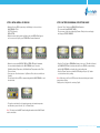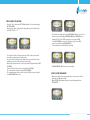
1
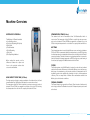
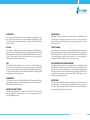
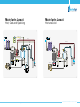
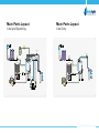
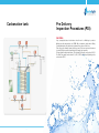
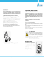
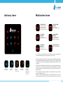
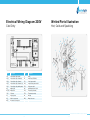
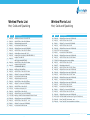
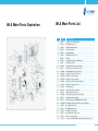
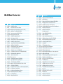
WL4 Firewall
Technical Manual
Index
Machine Overview .
Mains Parts Layout - Hot, Cold and Sparkling
Mains Parts Layout - Hot and Cold
Mains Parts Layout - Cold and Sparkling
Mains Parts Layout - Cold Only
Carbonation Tank
Pre Delivery Inspection Procedures (PDI) .
Installation Procedures
Instructions on Changing the CO2 Bottle
Operating Instructions
Maintenance and Servicing
Sanitising or Descaling
Fault Finding
Advisory Icons
Malfunction Icons
Technical Specifications and Warranties
ROHS
BioCote®
Main PCB Schematic Diagram - Hot, Cold and Sparkling
Electrical Wiring Diagram 230V - Hot, Cold and Sparkling
Electrical Wiring Diagram 230V - Hot and Cold
Electrical Wiring Diagram 230V - Cold and Sparkling
Electrical Wiring Diagram 230V - Cold Only
Wetted Parts Illustration - Hot, Cold and Sparkling
Wetted Parts List- Hot, Cold and Sparkling Main Parts Illustration - Exploded View
Main Parts List PCB Programming Procedure 4
8
9
10
11
12
13
15
17
19
21
22
23
24
25
27
29
29
30
31
32
33
34
35
36
38
39
42
Waterlogic 4 Firewall Technical Manual - Issue A, October 2010
2
3
Machine Overview
WATERLOGIC 4 FIREWALL
STANDARD COLD TANK (2 Litres)
The Waterlogic 4 Firewall is available
in the following options:
a) Cold, Hot & Sparkling (Full Option)
b) Cold & Hot
c) Cold & Ambient
d) Cold & Sparkling
e) Cold Only
f) Cold Sparkling & Ambient
HOT TANK
The standard cold tank is manufactured from 304 StainlessSteel which is
noncorrosive. The temperature of the Cold Tank is controlled by a microprocessor
and can be set between 3°C and 12°C.We recommend the cold water to be set at
5°C, this being ideal temperature for a cold drink. The capacity of the tank is 2 litres.
When reading this manual, note the
differences between the options and
focus on the particular sections that
concern the unit installed.
HIGH CAPACITY COLD TANK (4,5 Litres)
The high capacity cold tank is a unique combination of ice bath and direct chill, and
is manufactured from 304 Stainless Steel which is noncorrosive and inert.
The temperature of the Cold Tank is controlled by a microprocessor and can be set
between 3°C and 5°C. We recommend the cold water to be set at 5°C, this being
ideal temperature for a cold drink. The capacity of the tank is 4.5 litres.
The hot water temperature is controlled by a Microprocessor and can be set between
70°C and 93°C.It is recommended that the hot temperature is set at 87°C, this being
the ideal temperature for instant drinks. A thermal cut out is fitted to the Hot Tank to
prevent overheating. The tank is fed water via a polyphosphate filter to increase the
tank life. Setting the hot water temperature at 87°C also helps stop scale forming in
the hot tank, prolonging the 500Watt element and the Hot Tank.
FILTERS
The filtration system on the WL4 Firewall is designed to reduce dirt and sediment
particles from the water. Furthermore, the Activated Carbon process will remove a
whole range of contaminants e.g. chlorine and pesticides. It is important for the UV
sterilization system to be supplied with clean water in order to achieve maximum
efficiency. There are many kinds of different filter combinations available from
Waterlogic to suit local water conditions.
FIREWALL CHAMBER
The Firewall chamber incorporates the in-Faucet UV and is made of stainless steel
and is highly reflective.The Chamber houses the UV lamp and quarts spiral as well
as the faucet
Waterlogic 4 Firewall Technical Manual - Issue A, October 2010
4
5
IN faucet UV
WATER VALVES
UV LAMP
PLASTIC PANELS
PCB
PARTS REQUIRED FOR SPARKLING WATER
The Unique design allows the faucet area to be steralised before, during and after
every dispense. There are two types of sensors available, the CDS UV sensor that
detects if the UV lamp is working and the UV sensor that monitors the UVC intensity
from the UV lamp.
The UV light is an 11Watt germicidal lamp at a wavelength of 253.7 NM, which is
very efficient at destroying bacteria in water. The UV lamp is situated in the Firewall
Chamber surrounded by a quartz spiral that attains NSF standard 55 purification
of water. The lamp must be replaced at 6 months intervals, and the quartz spiral
cleaned by using a ultrasonic bath if needed
The PCB (Printed Circuit Board) is the control unit for the WL4 Firewall, it is
responsible for the functions of all the mechanical and electrical parts (24V DC).
The microprocessor drives the display (at the top of the WL4 Firewall) which informs
the user of the status of the unit. There are two different Models of the display PCB
depending on the UV sensor type used.
COMPRESSOR
The compressor operates at 220-240V at 50Hz. It uses 75 gramms of R134a nonOzone depleting refrigerant gas for the High Capacity cold tanks and 45 gramms of
R134a gas for the Standard cold tank.
WATER PIPES AND FITTINGS
Dispensing of water to the customer is achieved by means of a 24V DC electrical
solenoid valve. The valves are energized every time the customer pushes the
dispense button for a drink. DC voltage is used to give a positive and quieter action
of the solenoid valve.
The moulded panels are made from recyclable ABS plastic. All the ABS plastic
panels are UV resistant and meet the standards of CE and UL. Please note that the
WL4 Firewall should not be exposed to direct sunlight. Placing the WL4 Firewall
in direct sunlight from a window, close to a radiator, or in a room of high ambient
temperature, will affect the efficiency of the refrigeration circuit.
CO2 Cylinder & Gas Regulator: The units with the option of sparkling water will
need CO2 gas, food grade carbon dioxide. This gas is stored in cylinders in a liquid
form. The cylinders are usually painted grey or black (regulation requirement for
CO2). The gas regulator, which comes with the unit, controls the flow of CO2 to the
carbonation tank; it reduces the pressure of the CO2 gas to 45PSI which is needed
to make high quality sparkling water.
Water Pump
The water pump is 24V DC and forces the pre-chilled cold still water into the
carbonation tank at a minimum pressure of 45PSI. This pressure is required to
overcome the internal pressure from the CO2 gas which is in the tank and will give
a average of 4.8 grams of C02 per litre of water.
The inlet and the internal water circuit pipe size is 1/4” and 5/16”. The entire internal
water circuit and all the components which come in contact with water are food
grade NSF / WRAS approved.
Waterlogic 4 Firewall Technical Manual - Issue A, October 2010
6
7
Main Parts Layout
Main Parts Layout
Hot, Cold and Sparkling
CHECK VALVE
Hot and Cold
CO2 In
IN (Water)
IN (Water)
HOT WATER OUT
HOT WATER OUT
AIR VENT
HOT WATER OUT
AIR VENT
SOLENOID
VALVE 3
COLD
SENSOR
COLD
WATER
OUT
SAFETY
VALVE
SOLENOID
VALVE 5
SOLENOID
VALVE 1
FILTER
SOLENOID
VALVE 2
FILTER
FILTER
SOLENOID
VALVE 5
SOLENOID
VALVE 2
COLD WATER OUT
SOLENOID
VALVE 3
COLD
SENSOR
COLD &
SPARKLING
TANK
CONDENSER
COLD
TANK
CONDENSER
HOT
TANK
HOT
TANK
WATER IN
SOLENOID
VALVE 1
FILTER
SOLENOID
VALVE 6
SPARKLING WATER OUT
FILTER
DRYER
COMPRESSOR
FILTER
DRYER
SOLENOID
VALVE 4
FAN MOTOR
DRAIN
VALVE
DRAIN
VALVE
COMPRESSOR
DRAIN
VALVE
FAN MOTOR
CHECK
VALVE
DRAIN
VALVE
DRAIN
VALVE
DRAIN
VALVE
PUMP
Waterlogic 4 Firewall Technical Manual - Issue A, October 2010
8
9
Main Parts Layout
Main Parts Layout
Cold and Sparkling
Cold Only
IN (Water)
IN (Water)
CHECK VALVE
CO2 In
SOLENOID
VALVE 3
COLD
SENSOR
COLD
WATER
OUT
SAFETY
VALVE
SOLENOID
VALVE 5
SOLENOID
VALVE 1
FILTER
SPARKLING WATER OUT
FILTER
FILTER
COLD WATER OUT
SOLENOID
VALVE 3
COLD
SENSOR
COLD &
SPARKLING
TANK
CONDENSER
SOLENOID
VALVE 5
COLD
TANK
CONDENSER
WATER IN
SOLENOID
VALVE 1
FILTER
SOLENOID
VALVE 6
FILTER
DRYER
FILTER
DRYER
COMPRESSOR
SOLENOID
VALVE 4
FAN MOTOR
DRAIN
VALVE
COMPRESSOR
FAN MOTOR
DRAIN
VALVE
DRAIN
VALVE
DRAIN
VALVE
CHECK
VALVE
PUMP
Waterlogic 4 Firewall Technical Manual - Issue A, October 2010
10
11
Carbonation tank
Pre Delivery
Inspection Procedures (PDI)
CAUTIONS:
Only competent trained technicians should work on Waterlogic products.
Waterlogic units may weigh over 25KG. We recommend caution when lifting.
Packing materials could present a trip hazard. Keep them off the floor.
Take care not to allow the power lead to get wet. If the lead gets wet it must not
be used. CO2 gas used for sparkling units is under high pressure.
Follow cylinder safety instructions. For Hot and Cold units, omit section 8,10, 12.
For Cold Only units, omit section 8, 10, 12, 13, 15. For Cold and Sparkling units,
omit section 13, 15.
Waterlogic 4 Firewall Technical Manual - Issue A, October 2010
12
13
1. Remove packing straps and unpack unit and visually inspect
for any damage. (Report any defects to Waterlogic as soon as possible).
2. Place the unit on a suitable work bench.
3. Open the top cover by removing the screws and releasing the 2 clips
in the dispense area then slide the lid forward and lift up.
Use the top support bar to hold top open.
4. Visually inspect all electrical connections and power lead.
5. Visually inspect all water connections.
6. Remove the three screws on top of the Firewall Chamber and inspect
the quartz spiral for damage and re-assemble.
7. Connect to a potable drinking water supply via a 1/4” John Guest tube
limited to 3 bar.
8. Connect to a CO2 regulator via a 1/4” John Guest tube and set to 3 bar.
9. Connect to an appropriate power supply.
10. Turn CO2 on and lift yellow safety valve for 5 seconds.
11. Close top cover and turn on water then the power switch.
(Note the unit will not operate with the top cover open)
12. The unit will auto fill the sparkling water tank.
13. Note the telephone icon might flash if the hot tank is not full of water.
The icon will extinguish as you continue through this PDI procedure.
14. Select the cold button until water flows clearly.
15. Select hot + extra hot button until water flows clearly.
16. After cold/hot has filled, turn on heater/compressor switch allow up to an hour
for the unit to heat and chill.Test water temperatures and ensure the water tastes
acceptable.
17. Check WL4 Firewall functions.
18. Turn off power, water and CO2 if a sparkling unit.
19. Turn unit around and drain from rear drain valves.
20. Clean and repack ready for despatch.
21. Waterlogic recommend that all units are fully electrically (PAT) tested
on site by the commissioning engineer as damage may have occurred during
transit to the unit’s final destination.
Installation Procedures
Important notice: This procedure should only be carried out by a technician
trained by Waterlogic International or by an approved distributing agent.
Note: This appliance is intended for indoor use only. Cleaning of Waterlogic
products should not be carried out using a jet washer.
1. Build the WL4 Firewall base cabinet if required using the separate instructions found
in the base cabinet box.
2. Mount the WL4 Firewall on a firm flat surface so that it cannot topple or fall from a
counter top. Level the WL4.
3. It is advisable that the water and electricity supply are within two meters of the
WL4 Firewall and that the water isolation valve and power supply are accessible.
The WL4 Firewall should not be installed using an extension lead.
The water supply should be from a potable source.
4. Open the top cover by removing the screws and sliding the two locking lugs,
located on the underside front of the top cover either side of the faucet, inwards.
5. Slide the top cover slightly forward to release the locks and then lift from the front
upwards. Use the top cover support strut, located on the left hand side panel, to
hold the top cover safely open.
6. If installing a sparkling water WL4 Firewall then please read the following section.
If not then proceed directly to paragraph 7. Prepare the CO2 gas bottle by removing
the dust cover (if fitted). Face the bottle away from you and momentarily turn on the
gas to purge any dirt or dust from the bottle fitting prior to attaching the CO2 pressure regulator. Attach the CO2 pressure regulator to the CO2 bottle and then attach
to the WL4 Firewall CO2 ‘IN’ bulkhead connector using 1/4” flexible pipe.
Turn on the CO2 gas bottle. The pressure regulator should be pre-set at 45 PSI (3
bar). If the pressure reading is higher or lower than 45 PSI, then please adjust it to
the correct setting. The CO2 bottle should be secured inside the base cabinet, or
secured within a cabinet adjacent to the WL4 Firewall, so the bottle cannot topple
over. The CO2 system in the WL4 Firewall will pressurise. It is required to purge
some CO2 gas through the system to remove any trapped air. This is achieved by
Waterlogic 4 Firewall Technical Manual - Issue A, October 2010
14
15
lifting the WL4 Firewall pressure release valve (yellow), located beside the UV lamp
assembly, for approximately 2 seconds.
7. Connect the water supply. All water sources should be potable. Allow the water
supply to run clear of any sediment before connecting to the WL4 Firewall. The minimum pressure for the WL4 Firewall to function correctly is 38 PSI (2.6 bar). The ideal
pressure is 45 PSI. The maximum pressure 60 PSI.
8. Check the electrical wall socket (polarity) and then make the electrical connection to the WL4 Firewall by plugging the power lead in to the socket on the rear of
the WL4. Then connect to the electrical feed wall power outlet. Turn on the power
supply to the WL4 Firewall.
9. Close the top cover and turn on the red power switch. The WL4 Firewall will go
through a self test cycle and light the WL4 Firewall icons automatically. When the
self test cycle completes, the sparkling water model will automatically fill with water, whilst still water models will need to be manually flushed through with water by
depressing the cold water dispense button. (Please note carbon filters should be
pre-flushed before commissioning the WL4 Firewall so that excessive carbon fines
do not get into the WL4 Firewall tanks and solenoids). When the WL4 Firewall stops
filling, flush 10 litres of water through the WL4 Firewall by depressing the cold, sparkling and hot buttons. Turn on the green heater and compressor switch (rear) and
the WL4 will start to heat and cool.
10. The water temperature of the WL4 Firewall is factory set at 5°C for still and sparkling water and 87°C for hot water. The temperature can be adjusted - see page 34
‘PCB Programming Procedures’.
11. Lift the top cover (power is isolated by top cover switch) and carry out a visual
inspection for any water or CO2 gas leaks.
12. Replace any covers and now test the water for taste. Any hint of plastic taste in
the water means the WL4 Firewall needs to be flushed with an additional 10 litres.
13. The WL4 Firewall should be sanitised at installation. ‘Sanitising or Descaling’.
14. The WL4 Firewall must not be installed in direct sunlight, adjacent to a heat
source, or in an ambient room temperature above 30°C or below 5°C
Instructions
on Changing the CO2 Bottle
Removing THE empty Co2 bottle
Turn off the empty bottle and disconnect from gas regulator.
Connecting new Co2 bottle
• Before connecting new Co2 bottle, remove dust cap.
• Face the gas bottle away from yourself and purge the bottle for 2 seconds
to release any air and clean any dirt or dust from the top of the bottle.
• Connect bottle to gas regulator and turn on. The pressure should read 3 Bar.
Adjust if needed.
Purging the WL4 FIREWALL
• Lift the yellow lever under top cover for 5-10 seconds to purge the gas line
and carbonator.
• Place a container of at least 5 litre under the faucet and dispense sparkling
water until just gas is dispensed from the faucet. The WL4 Firewall will now refill. This takes about 4 minutes. When the pump has stopped turn the gas bottle off.
• Record the regulator pressure, normally 3 Bar. After 5 minutes check the gauge
for any pressure drop as this indicates a leak. Remember to turn on the CO2 bottle!!
Waterlogic 4 Firewall Technical Manual - Issue A, October 2010
16
17
INSTALLATION KIT
1-20 metres of 6mm 5/16 inch water pipe, PRV (pressure reducing valve) set at 3 bar
or 42 psi, Non return valve, Self-cutting saddle valve or isolating valves, Moulded
plug fitted, CO2Gas (if required), CO2 Regulator, Customer Handbook Allow 1 Hour
•The WL4 Firewall must be installed according to the local guidelines.
•Waterlogic strongly recommend that a pressure reducing valve is set at 3 bar
and a non-return valve be used on all WL4 Firewall installwations.
•The WL4 Firewall should not be connected to water supplies of unknown bacterial
quality or those not already fit for human consumption. The WL4 Firewall should only be connected to a Potable drinking water supply.
•The filter on the WL4 Firewall must be changed every 6 months.
•The UV lamp on the WL4 Firewall must be changed every 6 months.
•The cold tank should also be flushed and sanitised every 6 months.
•Waterlogic International strongly recommends the use of an anti-flood device.
•Figure 1 is the recommended installation kit.
Operating Instructions
Your Waterlogic 4 Firewall is generally ready for use. If the sleeping cat symbol is
, the WL4 Firewall has entered sleep mode, pushing any button will
illuminated
bring the WL4 Firewall out of sleep mode. Sleep mode is an energy saving feature
that minimizes power consumption when the WL4 Firewall is not in use over extended
periods.
Dispensing your choice of water is very simple,
as follows:
1. Place your cup centrally in the dispensing area
2. Select the type of water you wish to be dispensed and press the corresponding
button.
3. Keep the button depressed until your cup has reached the desired level, and
then release the button.
4. Whist the dispense button is depressed, a coloured light will illuminate the
dispensing area of your WL4 Firewall.
HOT WATER CAUTION
Always place cup / mug in the centre of the drip tray. Always use
a ceramic cup or a cup suitable for use with hot water. Do not
hold cup or place hands in dispensing area whilst dispensing
water. Do not dispense water in a stop start style of vending
(hold button continuously until cup is full).
Never try to fill more than one vessel at a time.
Fold Down Cup Holder
Fig 1. Waterlogic Installation Kit
The fold down cup holder should be used to
reduce splashing when smaller receptacles
are in use. It is only intended for small/plastic
cups when filled which do not exceed 500
grams (16 ounces).
Please fold up when not in use.
Waterlogic 4 Firewall Technical Manual - Issue A, October 2010
18
19
Operating Instructions
Maintenance and Servicing
COLD WATER
6 MONTH SERVICE PROCEDURE
Press the cold water button. Cold water will be dispensed immediately.
This procedure should only be carried out by persons trained by Waterlogic
International or their approved distributors.
AMBIENT WATER
Press the ambient water button and water will be dispensed.
SPARKLING WATER
Press the sparkling water button. Sparkling water will be dispensed
immediately.
HOT water
Press and hold the hot water and extra hot water buttons together
for 3 seconds (This safety feature prevents hot water from being
dispensed accidentally, especially by children). Amber lighting will
illuminate the dispensing area to confirm your selection, and hot
water will be dispensed following a 3 second pause.
EXTRA HOT water
Press the extra hot water button and the hot water icon on
the display panel will light to indicate that the water is heating.
Once the icon turns off, the water is at the correct temperature
and extra hot water can be dispensed following the same
method as Hot Water.
The following instructions cover models that can include Hot, Cold, Ambient and
Sparkling water.
• Every six months the filters and UV lamp must be changed.
• The Firewall quartz spiral must be removed, checked and cleaned every six
months if needed.
• A WL4 Firewall with a hot water option may require having any calcium build up
inside the hot tank removed, depending on local water conditions.
• No paperwork or cleaning records should ever be stored inside the WL4 Firewall.
1. Isolate the power to the WL4 Firewall by turning off the green and red switches
at the rear of the WL4 Firewall and by removing the power cord.
2.To access the filters slide the locking lugs located adjacent to the water dispensing
faucet inward, then slide the top cover forward and lift it upward and back onto its
hinges. Hold the top cover open using the top cover support strut located on the
left hand side panel.
3.The two Waterlogic twist filters are at the front left hand side protruding through
the WL4 Firewall’s upper metal shelf. Grip the 1st filter on the left and twist it clock
wise to release it. This action will also isolate the water supply. Please remember
that all Waterlogic twist filters are left handed thread. Pull the filter body upward
when it releases and take precautions not to allow the used filter to drip water inside
the WL4 Firewall or you can use the filter tool available from Waterlogic loosen and
tighten the filter.
4.Turn off the CO2 supply (if servicing a sparkling water WL4 Firewall and drain the
WL4 Firewall through the drain valves located at the rear. Have an adequate size
container to drain the tanks into. (5L of water)
5. Remove the top cover of the Firewall chamber and remove the UV lamp first and
then release the water feed fittings to the quartz spiral. Remove the quartz spiral.
Clean the spiral removing any lime scale that may have adhered to the quartz surface.
It is important to clean the quartz to allow maximum UV purification to take place.
6.To sanitise the cold tank introduce sanitisation fluid at the back of the machine
Waterlogic 4 Firewall Technical Manual - Issue A, October 2010
20
21
and fill the cold tank with a mix of water and sanitisation fluid.
7. Replace the UV lamp and reconnect the UV loom. Do not touch the UV lamp with
your bare hands as this will shorten the lamp life.
8.Machines with the Hot Option. Remove and inspect the faucet. If the faucet is
cracked or has excessive build of calcium that cannot be easily cleaned then replace
the faucet. Please ensure that you wear cleaning gloves when handling the faucet.
9.Pre flush the carbon filters outside the WL 4 Firewall to waste and then fit into the
WL 4 Firewall screwing in anti clockwise.
10.De-scale the hot tank if required.
11.Carry out a visual inspection of the WL 4 Firewall’s water and electrical connections
and components and take any remedial action required to prevent a fault.
Clean the refrigeration condenser and fan if required.
12. If servicing a sparkling water unit turn back on the CO2 and purge the system
by lifting the yellow CO2 relief valve lever located beside the UV lamp assembly for
1 second. Check the regulator pressure is set at 45 PSI and there are no CO2 leaks.
13. Close the top cover, reconnect the power cord and turn on only the red switch
at the rear of the WL4 Firewall. The WL4 Firewall will go through a self test cycle,
the icons will light up. The sparkling water will fill automatically. But if it is a Cold only
or Hot & Cold WL4 Firewall then you will need to manually ill the WL4 Firewall by
depressing the cold water button. You will also need to fill the Hot Tank manual by
depressing the two hot dispense buttons until water is dispensed.
14. Flush the sparkling and still or ambient water for about 10 litres to generate the
filters or until all traces of Chlorine have been removed. This can be checked by
using Chlorine test strips. Flush the hot tank to ensure it is full of water and then turn
on the green switch at the rear of the WL4 Firewall. The unit will now heat and cool.
15. Wipe the outside surfaces (non abrasive cleaner), clean the drip tray, check
there is a 5 cm air gap around the WL4 Firewall
16. Taste the water, ensure there are no carbon fines in the water, check the WL4
Firewall functions to the customer’s satisfaction. Should there be any taste issues or
carbon fines still in the water then flush the WL4 Firewall again.
SANITISING oR DESCALING
2.Mix a solution of sanitiser in the empty filter housing.
3.Turn off the water supply to the WL4 Firewall, release the internal water pressure
by momentarily pushing the cold water button. Disconnect the water feed pipe from
the rear water in bulkhead of the machine.
4.Fit the water feed pipe to the inlet side of the filter housing with the sanitiser in.
Connect a length of 1/4” inch water pipe from the outlet of the filter housing to the
water ‘IN’ bulkhead at the rear of the machine.
5.Release the top cover of the machine by sliding the top cover locking lugs,
located either side of the faucet nipple, inward. Slide the top cover forward and then
lift it upward and back onto it hinges. Hold the top cover open using the support
strut located on the left hand side panel. The internal power to the WL4 Firewall is
isolated when you lift the top cover.
6. Bypass the WL4 Firewall internal twist filters as no sanitiser should enter the filters.
These can be bypassed by using dummy (empty) filters. (same applies for de-scale)
7. Close the top cover, the WL4 Firewall will go through a self test cycle, when this
is completed flush the cold water until the sanitiser exits the faucet. If sanitizing a
sparkling water WL4 Firewall flush the sparkling water again until the sanitiser exits
the faucet. Please ensure no sanitiser is allowed to enter the hot tank. Let the WL4
Firewall stand for a minimum of 15 minutes and then flush out the sanitizing solution.
Replace or refit the filters, remove the empty filter housing and reconnect the water
supply to the WL4 Firewall.
8.Replace the faucet nipple if it is scratched, cracked, or has calcium build up on it.
9.Clean all outside surfaces of the machine, including the fold down cup stand.
Remove and clean theWL4 Firewall’s drip tray and grill.
10.The above method can be used to remove calcium from the hot tank by using a
non toxic de-scale solution or powder (citric acid based) and flushing the hot water
buttons instead of cold. Please read de-scale packet instructions.
FAULT FINDING
All fault finding procedures must be carried by a technician trained by Waterlogic
International or their nominated distributor. Please take great care and suitable
health and safety measures when fault finding on live electrical parts.
Please ensure that you do not accidentally drop sanitiser or de-scaler on any of the
WL4 Firewall’s water or electrical connections.
1. An empty filter housing, as used on the AMETEK filter system fitted with in and
out pipe fittings, will be needed to mix the sanitizing solution. Flush the solution into
the machine from the rear bulkhead. Sanitising the machine using this method will
allow the whole cold water system from entry to exit to be sterilised, including the
carbonation pump.
Waterlogic 4 Firewall Technical Manual - Issue A, October 2010
22
23
Malfunction Icons
Advisory Icons
No water supply
Check the water supply
is turned on, if fault
persists please call your
authorised service agent
A FAULT HAS BEEN
DETECTED
Please call your
authorised service agent
The UV lamp
has failed
Please call your
authorised service agent
A LEAK HAS BEEN
DETECTED
Please turn off the water
supply and call your
authorised service agent
FILTER NEEDS
REPLACING
Please call your
authorised service agent
THE DRIP TRAY IS FULL
Please empty the drip tray
Note - If all the icons should flash and an audible alarm sounds, please switch the
machine off immediately and call you authorised service agent.
The UV lamp
is operating
The cold tank
is chilling
Extra hot
water has
been selected
The hot tank
is heating up
Sleep Mode
- press any
button to bring
machine out of
sleep mode
1. No flow of water: Ensure that there is a water supply to the WL4 Firewall from the
building and that the installation isolation valve is turned on. If the installation kit has
an anti-leak device included in it (as Waterlogic Installation kit) then make sure it has
not tripped.
2.No flow of water: Check that the water filters are not blocked and that they are
in date and are screwed home securely into the filter head. Waterlogic recommend
filters are changed at 6 months. Check that the internal leak detection tray has not
filled with water.
3.The hot water is not hot and cold water is not cold: Make sure the green heater
compressor switch is turned on.
4.There is hot water flow but cold water is not flowing: This may be due to the
cold water tank being frozen. If so disconnect power supply for one hour to allow
Waterlogic 4 Firewall Technical Manual - Issue A, October 2010
24
25
the tank to defrost, and then flush the cold water system. Check the temperature
settings are correct. If the cold tank is not frozen then check the solenoid valve is
operating correctly and being turned on and off when you push the cold button.
5.There is cold water flow but hot water is not flowing: This may be due to calcium
build up in the hot tank or the hot water outlet. De-scale the hot tank. Check the hot
water solenoid valve functions correctly and turns on and off when you hold the hot
and extra hot buttons together for 3 seconds.
6.Low flow of cold water or hot water or both: Check the building water pressure
to the WL4 Firewall is 45 PSI. Check the filters are not partially blocked, that the
solenoid vales function correctly, hot tank calcium build up need to be de-scaled,
cold tank ice build up needs to be defrosted.
7. No sparkling water: Ensure the CO2 bottle is full and turned on and set at 45 PSI.
Turning the gas pressure above 45 PSI can stop the production of sparkling water.
Check the pump Icon. If flashing turn the power to the WL4 Firewall off for 1 minute
and then back on to reset the carbonation pump. The pump will time out if it runs
for more than 5 minutes continuously.
8.Bad or plastic taste: If the WL4 Firewall is new it may need flushing for a longer
period.
Water leaks: Most leaks will be detected by either the internal WL4 Firewall leak
detection system that will trigger an alarm, or it will trip the Waterlogic block located
on the installation kit. Should you see water leaking from the WL4 Firewall, isolate
the supply and start normal fault finding procedures.
No power: Check the building electrical supply to the WL4 Firewall is on and that
the power cord is plugged in. Ensure the red power switch at the rear of the WL4
Firewall is on. Test the WL4 Firewall fuse. Check that the top cover isolation switch
is being activated by the top cover being locked in place correctly. If all these points
are OK then start normal fault finding procedures.
All Icons flashing and audible alarm: An over heat fault has been detected please
switch the WL4 Firewall off immediately and start fault finding procedures.
Technical Specifications
and Warranties
SAFETY
Subject to the standard terms and conditions of sale (a copy of which has been
provided to you), neither Waterlogic International Limited (“Waterlogic”), nor any
affiliated companies shall be liable for any damage which could affect, directly or
indirectly, any person or property.
Please be aware that any warranties accompanying the sale of our products will be
invalidated by any of the following:
• Incorrect installation
• Incorrect use of the WL4 Firewall
• Unsuitable electrical and water supply
• Major short-coming of maintenance
• Technical interventions or alterations of an unauthorised nature
• Adoption and use of unapproved spare parts
• Engagement of untrained personnel
Waterlogic has a policy of constant and continual improvement and therefore reserves the right to change specifications without prior notice, other than in the case
of significant changes.
Waterlogic 4 Firewall Technical Manual - Issue A, October 2010
26
27
Description
WL4
HCS
WL4
HC
Machine Size
WL4
CA
WL4
C
WL4
CAS
WL4
CA
WL4
C
418mm(W) x 803.4mm(H) x 467.3mm(D)
Mini & BC Size
418mm(W) x 1238mm(H) x 470mm(D)
35kg 27kg 34kg 26kg 26kg 34kg 25kg 24kg 24kg
Base Cabinet
Weight
18kg
Power Supply
220-240 Volt / 50Hz
Heater
WL4
HC
417mm(W) x 439mm(H) x 470mm(D)
Base Cabinet Size
Machine Weight
WL4
CS
500W 500W N/A
End of Life
Non Eu Countries
At the end of this products life, please ensure that it is disposed of in an
environmentally friendly manner which is in line with your Country requirements/
guidelines.
WEEE (EU ONLY)
N/A
N/A
N/A 500W N/A
N/A
Please be aware that our products are covered by the Waste Electrical and Electronic
(WEEE) directive (2002/96/EC). The symbol shown above denotes that the product
should not be disposed of with general/household waste. Please contact your supplier/service agent who will arrange for the collection and disposal of this product.
Fan
16W
16W
16W
16W
16W
16W
16W
16W
16W
Compressor
114W
114W
114W
114W
114W
114W
114W
114W
114W
Pump
12W
N/A
12W
N/A
N/A
12W
N/A
N/A
N/A
ROHS
UV Lamp
11W
11W
11W
11W
11W
11W
11W
11W
11W
Control Units
15W
15W
15W
15W
15W
15W
15W
15W
15W
All Waterlogic machines comply with EC Directive (2002/95/EC) on the Restriction
of the Use of Certain Hazardous Substances in Electrical and Electrical Equipment
(RoHS).
Unit Total
Refrigeration Gas
R134a
668W 656W 168W 156W 156W 168W 656W 156W 156W
75g
75g
75g
75g
75g
75g
45g
45g
45g
4.5
Litre
1.2
Litre
4.5
Litre
1.2
Litre
4.5
Litre
4.5
Litre
4.5
Litre
4.5
Litre
2
Litre
2
Litre
N/A
N/A
N/A
N/A
2
Litre
1.2
Litre
N/A
N/A
CO2 Bottle (Max)
10kg
N/A
10kg
N/A
N/A
10Kg
N/A
N/A
N/A
Water Connection
1/4” 1/4” 1/4” 1/4” 1/4” 1/4” 1/4” 1/4” 1/4” Hose Hose Hose Hose Hose Hose Hose Hose Hose
Cold Tank Capacity
Hot Tank Capacity
Minimum Water
Pressure
Megapascal (Bar)
Maximum Water
Pressure
Megapascal (Bar)
Recommended Water
Pressure
Megapascal (Bar)
Hot Water
Temperature
0.15
(1.5)
0.15
(1.5)
0.15
(1.5)
0.15
(1.5)
0.15
(1.5)
0.15
(1.5)
0.15
(1.5)
0.15
(1.5)
0.15
(1.5)
0.35
(3.5)
0.35
(3.5)
0.35
(3.5)
0.35
(3.5)
0.35
(3.5)
0.35
(3.5)
0.35
(3.5)
0.35
(3.5)
0.35
(3.5)
0.30
(3.0)
0.30
(3.0)
0.30
(3.0)
0.30
(3.0)
0.30
(3.0)
0.30
(3.0)
0.30
(3.0)
0.30
(3.0)
0.30
(3.0)
87°C
87°C
N/A
N/A
N/A
N/A
87°C
N/A
N/A
Cold Water
Temperature
6°C
6°C
6°C
6°C
6°C
6°C
6°C
6°C
6°C
Sparkling Water
Temperature
6°C
N/A
6°C
N/A
N/A
6°C
N/A
N/A
N/A
BioCote® (ANTI-MICROBIAL SOLUTION)
For your added protection this product incorporates BioCote® antimicrobial technology. Silver, in the form of silver ions, is the active ingredient utilised in BioCote®.
This silver technology is manufactured into the surface of our products, giving them
built-in sustainable antimicrobial protection.
BioCote’s silver technology has been tested by an independent laboratory to show
its ability to inhibit the growth of bacteria, mould and fungi by up to 99.9% over a 24
hour period and for the duration of the machine life.
FREQUENTLY ASKED QUESTIONS ABOUT BioCote®:
Why use BioCote®? BioCote® will help reduce the risk of cross-contamination. You
may not want to think about it, but every surface in the working environment is a
potential breeding ground for Bacteria.
How is it applied? BioCote® is applied via an additive into the manufacturing process and will, therefore, be present throughout the moulded or painted parts.
How long will BioCote® last? BioCote® will last for the usual life expectancy of
your water dispenser. It will not wear or wash out with use or cleaning.
What bacteria is BioCote® effective against? BioCote® is effective against most
common bacteria, moulds and fungi.
Please note:
BioCote® is an additional line of defence to protect between cleaning routines,
it is not a replacement for your normal cleaning and sanitisation processes.
Waterlogic 4 Firewall Technical Manual - Issue A, October 2010
28
29
Main Pcb Schematic Diagram
Hot, Cold and Sparkling
Electrical Wiring Diagram 230V
Hot, Cold and Sparkling
POWER SOURCE
AC 230V/50Hz
PS3
R
GND
A
BR
1 2 3 4 5 6 7 8 910
FUSE
AD
BR
R
BK
BK
BK
BK
BL
PS1
5x20
W
LED PCB
123456789
MAIN PCB
DC 24V
BL
TS
RQ
PO
NM
DISPLAY PCB
123456
PS2
VU
123456
L
SW1
NOTE
R = RED, BL = BLUE,
BK = BLACK, BR = BROWN
G, Y = GREEN & YELLOW
A
B
C
D
E
F
G
H
I
J
K
L
24V in
Leak Detector
UV Detector
Drip Tray Sensor
Hot Tank Level Control
Sparkling Water Level Control
10 Pin Ribbon Cable
9 Pin Ribbon Cable
Hot Sensor
Cold Sensor
Ambient Sensor
UV
M
N
O
P
Q
R
S
T
U
V
W
To Hot Tank
230V AC In
To Compressor
Solenoid 4
Pump
Solenoid 6
Solenoid 5
Solenoid 3
Solenoid 2
Solenoid 1
Fuse 1 Amp
DANGER HIGH VOLTAGES PRESENT ON THIS PCB
CARE MUST BE TAKEN WHEN LIVE TESTING
12345
TH3
G, Y
JK
GH
TH2
TH1
12345
FI
SLS
12345
E
HLS
DS
CDS
123456789
CD
WLS
1 2 3 4 5 6 7 8 910
B
PF BL
10A
12345
BR
SW2
BUTTON PCB
SW3
SW4
OV
20S1
20S2
20S3
20S5
20S6
UV
AC 230V
20S4
MC
P
MFC
H
DC 24V DC 24V DC 24V DC 24V DC 24V DC 24V DC 24V AC 230V AC 230V AC 230V
BT PCB
Mark
Description
Mark
Description
0S1
20S2
20S3
20S4
20S5
20S6
0V
AD
Solenoid valve (for in water)
Solenoid valve (for hot water)
Solenoid valve (for cold water in)
Solenoid valve (for cold water)
Solenoid valve (for cold water out)
Solenoid valve (for sparkling water)
Thermostat for overheat (hot tank)
Adaptor 24V DC
MC
MFC
P
PF
PS1
PS2
PS3
SLS
Motor for compressor
Fan motor for compressor
Pump
Power Fuse (250V/10A)
Control power switch
Comp & heater power switch
Top cover power switch
Sparkling water level check
BT PCB
CDS
DS
H
HLS
Ballast PCB
UV sensor
Drip tray sensor
Hot water heater
Hot water level check
TH1
TH2
TH3
UV
WLS
Thermistor (hot water)
Thermistor (cold water)
Thermistor (over-heat)
UV lamp
Water leak sensor
Waterlogic 4 Firewall Technical Manual - Issue A, October 2010
30
31
Electrical Wiring Diagram 230V
Hot and Cold
Electrical Wiring Diagram 230V
Cold and Sparkling
POWER SOURCE
AC 230V/50Hz
PS1
AD
123456789
MAIN PCB
DC 24V
BL
20S3
DC 24V DC 24V DC 24V DC 24V
MFC
SW2
1 2 3 4 5 6 7 8 910
123456789
MAIN PCB
DC 24V
SW3
12345
12345
12345
BL
BL
DISPLAY PCB
123456
BUTTON PCB
SW1
SW4
NOTE
R = RED, BL = BLUE,
BK = BLACK, BR = BROWN
G, Y = GREEN & YELLOW
UV
AC230V
H
AC 230V AC 230V AC 230V
BK
BK
PS2
20S5
MC
LED PCB
TH3
BK
AD
OV
20S2
BR
BR
SW1
20S1
TH2
BK
PS1
123456
NOTE
R = RED, BL = BLUE,
BK = BLACK, BR = BROWN
G, Y = GREEN & YELLOW
SLS
PS3
123456
PS2
DS
CDS
123456789
BL
WLS
12345
DISPLAY PCB
GND
1 2 3 4 5 6 7 8 910
BR
BK
BK
123456789
BR
BK
BK
1 2 3 4 5 6 7 8 910
GND
R
PF BL
10A
1 2 3 4 5 6 7 8 910
R
BR
G, Y
123456
G, Y
PS3
POWER SOURCE
AC 230V/50Hz
LED PCB
TH3
12345
TH2
TH1
12345
HLS
DS
CDS
12345
WLS
12345
BR
PF BL
10A
20S1
20S3
20S5
20S6
MC
MFC
DC 24V DC 24V DC 24V DC 24V DC 24V AC 230V AC 230V
BUTTON PCB
SW3
SW4
UV
AC 230V
20S4
P
DC 24V
SW2
BT PCB
BT PCB
Mark
Description
Mark
Description
Mark
Description
Mark
Description
20S1
20S2
20S3
20S5
0V
AD
BT PCB
CDS
Solenoid valve (for in water)
Solenoid valve (for hot water)
Solenoid valve (for cold water in)
Solenoid valve (for cold water out)
Thermostat for overheat (hot tank)
Adaptor 24V
Ballast PCB
UV sensor
MC
MFC
PF
PS1
PS2
PS3
TH1
TH2
Motor for compressor
Fan motor for compressor
Power Fuse (250V/10A)
Control power switch
Comp & heater power switch
Safe power switch
Thermistor (hot water)
Thermistor (cold water)
20S1
20S2
20S3
20S5
AD
BT PCB
CDS
DS
Solenoid valve (for in water)
Solenoid valve (for ambient water)
Solenoid valve (for cold water in)
Solenoid valve (for cold water out)
Adaptor 24V
Ballast PCB
UV sensor
Drip tray sensor
MFC
PF
PS1
PS2
PS3
TH2
TH3
UV
Fan motor for compressor
Power Fuse (250V/10A)
Control power switch
Comp & heater power switch
Safe power switch
Thermistor (cold water)
Thermistor (over-heat)
UV lamp
DS
H
HLS
Drip tray sensor
Hot water heater
Hot water level check
TH3
UV
WLS
Thermistor (over-heat)
UV lamp
Water leak sensor
MC
Motor for compressor
WLS
Water leak sensor
Waterlogic 4 Firewall Technical Manual - Issue A, October 2010
32
33
Electrical Wiring Diagram 230V
Cold Only
Wetted Parts Illustration
Hot, Cold and Sparkling
POWER SOURCE
AC 230V/50Hz
TH2
G, Y
PS3
BK
BK
1 2 3 4 5 6 7 8 910
PS1
AD
BR
BK
BK
BL
123456789
MAIN PCB
DC 24V
BL
4
SW1
20S1
20S3
DC 24V
SW2
DC 24V DC 24V
MFC
AC 230V AC 230V
37
40
36
35 34
26
27
28
BUTTON PCB
SW3
43
SW4
UV
AC 230V
20S5
MC
58
9
123456
NOTE
R = RED, BL = BLUE,
BK = BLACK, BR = BROWN
Y = YELLOW, G, Y = GREEN & YELLOW
38
12
123456
PS2
25
23
123456789
BR
39
41
42
DISPLAY PCB
1 2 3 4 5 6 7 8 910
GND
24
LED PCB
TH3
12345
DS
CDS
12345
WLS
12345
PF BL
10A
12345
BR
BT PCB
Mark
Description
Mark
Description
0S1
20S3
20S4
20S5
20S6
AD
BT PCB
CDS
Solenoid valve (for in water)
Solenoid valve (for cold water in)
Solenoid valve (for cold water)
Solenoid valve (for cold water out)
Solenoid valve (for sparkling water)
Adaptor 24V
Ballast PCB
UV sensor
P
PF
PS1
PS2
PS3
SLS
TH2
TH3
Pump
Power Fuse (250V/10A)
Control power switch
Comp & heater power switch
Safe power switch
Sparkling water level check
Thermistor (cold water)
Thermistor (over-heat)
DS
MC
MFC
Drip tray sensor
Motor for compressor
Fan motor for compressor
UV
WLS
UV lamp
Water leak sensor
1
2
45
3
7
10
8
32
33
16
56
13
54
55
14
11
53
30
21 47
20
19
57 18
5
6
46
31
44
22
15
29
52
48 49
50
17
51
Waterlogic 4 Firewall Technical Manual - Issue A, October 2010
34
35
Wetted Parts List
Hot, Cold and Sparkling
NO
Part NO
1
2
3
4
5
6
7
8
PU-4028
PU-4031
PU-4010
PU-4016
PU-4008
PU-4031
PU-4066
PU-4022
9
PU-4076
10
PU-4031
11
PU-4075
12
13
14
15
16
17
18
19
20
21
22
23
24
25
26
27
PU-4029
PU-4031
PU-4011
PU-4016
PU-4010
PU-4031
PU-4011
PU-4031
CT-2039
PU-4031
PU-4008
CT-2073-A
PU-4008
PU-4031
PU-4011
PU-4016
Part Description
JG Bulkhead Connector Union 1/4" * 1/4"
JG LLD PE Tube - Blue O.D.1/4" 240mm
JG Equal Straight Connector 1/4"
Solenoid Valve DC24V 1000mm
JG Equal Elbow Connector 1/4" (PI0308S)
JG LLD PE Tube - Blue O.D.1/4" 285mm
JG Stem Elbow Connector 1/4" * 1/4"
OmnipureFilter Head Valved (Q VALVED HEAD JJ)
Omnipure Twist GAC 10"
with Polyphosphate (WL5540-P)
JG LLD PE Tube - Blue O.D.1/4" 48mm
Omnipure Non-Valved Head
(Q NON VALVED HEAD JJ)
WL5520 10" CBC (WL5520)
JG LLD PE Tube - Blue O.D.1/4" 41mm
JG Equal Tee Connector 1/4" (PI0208S)
Solenoid Valve DC24V 1000mm
JG Equal Straight Connector 1/4"
JG LLD PE Tube - Blue O.D.1/4" 55mm
JG Equal Tee Connector 1/4" (PI0208S)
JG LLD PE Tube - Blue O.D.1/4"
Drain Valve and Cap Ass'y 1/4
JG LLD PE Tube - Blue O.D.1/4"
JG Equal Elbow Connector 1/4" (PI0308S)
Waterlogic 4 H2CP C&S tank without UV Holder -Firewall
JG Equal Elbow Connector 1/4" (PI0308S)
JG LLD PE Tube - Blue O.D.1/4"
mm
JG Equal Tee Connector 1/4" (PI0208S)
Solenoid Valve DC24V 1000mm
Wetted Parts List
Hot, Cold and Sparkling
NO
Part NO
28
29
30
31
32
33
34
35
36
37
38
39
40
41
42
43
44
45
46
47
48
49
50
51
52
53
54
PU-4008
PU-4031
PU-4011
PU-4031
PU-4008
FU-0007-A
PU-4016
PU-4008
PU-4031
CT-2035-D
PU-4031
PU-4057
PU-4031
PU-4008
PU-4008
PU-4031
PU-4008
PU-4016
PU-4008
PU-4031
PU-4016
PU-4011
PU-4031
PU-4008
HT-3036-A
PU-4064
PU-4064
Part Description
JG Equal Elbow Connector 1/4" (PI0308S)
JG LLD PE Tube - Blue O.D.1/4"
JG Equal Tee Connector 1/4" (PI0208S)
JG LLD PE Tube - Blue O.D.1/4"
JG Equal Elbow Connector 1/4" (PI0308S)
Faucet uv sprial quartz
Solenoid Valve DC24V 1000mm
JG Equal Elbow Connector 1/4" (PI0308S)
JG LLD PE Tube - Blue O.D.1/4" 220mm
AQ&Q pump with connector & fitting
JG LLD PE Tube - Blue O.D.1/4"
JG Non-Return Valve 1/4"
JG LLD PE Tube - Blue O.D.1/4" 150mm
JG Equal Elbow Connector 1/4" (PI0308S)
JG Equal Elbow Connector 1/4" (PI0308S)
JG LLD PE Tube - Blue O.D.1/4" 70mm
JG Equal Elbow Connector 1/4" (PI0308S)
Solenoid Valve DC24V 1000mm
JG Equal Elbow Connector 1/4" (PI0308S)
JG LLD PE Tube - Blue O.D.1/4"
Solenoid Valve DC24V 1000mm
JG Equal Tee Connector 1/4" (PI0208S)
JG LLD PE Tube - Blue O.D.1/4" mm
JG Equal Elbow Connector 1/4" (PI0308S)
1.2L 230V 800W Steel None-Open Type Hot Tank(Sensor)
Silicon Tube 5/16" for hot water mm
Silicon Tube 5/16" for hot water Air Vent 460mm
Waterlogic 4 Firewall Technical Manual - Issue A, October 2010
36
37
WL4 Main Parts List
WL4 Main Parts Illustration
85
87
88/89/
90/91
86
93
94
2
58
57
62
63
64
65
66
96
95
59
61
60
83
84
92
1
56
76
77
78
79
80
81
82
3
4
5
71
7
8
9
10
11
12
13
14
20
19
15
16
24
25
18
17
23
28
29
30
26
53
55
41
40
32
39
38
35
21
22
74
73
72
70
69
67 68
46 44 50
42/43
46 51
52
47
54
48
49
31
33
6
75
27
34
36/37
NO
Part NO
1
2
3
4
5
6
7
8
9
10
11
12
13
14
15
16
17
18
19
20
22
23
24
25
26
27
28
29
30
31
PL-1321
PL-1328
ST-8260
EN-6059
EN-6117
ST-8285
EN-6119
PL-1335
PL-1318
PL-1312-C
PL-1317
PL-1344-A
PL-1320-A
ST-8267-A
ST-8267-B
PL-1319-B
ST-8266
CU-0055
PU-4064
PL-1354
PL-1354-A
ST-8261
EL-5128
ST-8264-A
ST-8284
PL-1327
ST-8286
PL-1329
EL-5027
CO-9001
Part Description
WL-4 Top Cover Safety support
WL-4 Mini Side Panel-L
WL-4 PCB Holder Bracket
Plastic PCB Support
Main PCB WL4000
WL4 Main PCB metal cover
LED PCB
WL-4 LED PCB Holder sealing Rubber
WL-4 LED hold Plate
WL-4 Firewall Front Upper Panel Silver
WL-4 Top Cover Lock with screw hole
WL-4 Adjustable drip tray grill Silver
WL-4 Drip Tray gill Silver ( Biocote)
WL-4 Drip Tray-sensor Pin(L)
WL-4 Drip Tray-sensor Pin(R)
WL-4 Drip Tray Silver ( Biocote)- WL Logo
WL-4 Drip Tray sensor Holder
WL-4 Air Vent Clip
Silicon Tube 5/16" for hot water
WL4 Firewall hot water faucet
WL4 Firewall hot water faucet Insert Pipe
WL-4 Adaptor Holder Bracket
WL4 Power adopter 2A UNIVERSAL with ST-8264-A
WL-4 Adaptor Fixing bracket Ver2 replaced ST-8264
WL4 adaptor metal cover
WL-4 Mini Side Panel-R
WL4 Micro SW metal cover
WL-4 Safety Micro Switch Cover
Micro Door Lock S/W only
Compressor (R134a 1/8HP) 230V/50Hz thermally protected
Waterlogic 4 Firewall Technical Manual - Issue A, October 2010
38
39
WL4 Main Parts List
NO
Part NO
32
33
34
35
36
37
38
39
40
41
42
43
44
45
46
47
48
49
50
51
52
53
54
55
56
57
58
59
60
61
ST-8258
PL-1311
ST-8207CN
PL-1251CN
CT-2028
CT-2039-A
ST-8256
CO-9041
CO-9008
ST-8255
PU-4022
PU-4029
PU-4010
PU-4016
PU-4011
PU-4066
ST-8276
CU-0001
CT-2036-B
PU-4008
CT-2037
PU-4057
CT-2073-A
PU-4140
EL-5100
ST-8283
EL-5122
CT-2035-D
ST-8257
EN-6120-B
Part Description
WL-4 Mini Down Base
WL-4 Leak Detection Sensor Bracket
WL3000 Leak containment tray Clip (sensor 0.5mm)
Unit Rubber Feet of BOA WL2000 Mini
Drain valve cap only (for 5/16" & 1/4" size)
Drain valve body only for 1/4"
WL-4 Mini Front support Frame-R
Wire Condenser for WL4
Domestic Filter Dryer (Chinese) WL650&WL2000
WL-4 Mini Front support Frame-L
OmnipureFilter Head Valved (Q VALVED HEAD JJ)
WL5520 10" CBC (WL5520)
JG Equal Straight Connector 1/4"(PI0408S)
Solenoid Valve DC24V 1000mm
JG Equal Tee Connector 1/4" (PI0208S)
JG Stem Elbow Connector 1/4" * 1/4" Acetal(PI220808S)
WL-4 Omnipure filter fixing bracket
Cushion for solenoid valve
Water level sensor
JG Equal Elbow Connector 1/4" (PI0308S)
Upper Safty Valve 1/4" for Sparkling Unit
JG Non-Return Valve 1/4"(1/4SCV)
Waterlogic 4 H2CP C&S tank without UV Holder -Firewall
JG End Stop 1/4" (PI4608S)
Brown Wire from Fuse holder to red S/W Including Fuse(WL-4)
WL-4 Electronics Cover Bracket
WL4 Wire from Philips Ballast to UV Lamp
AQ&Q Pump With Connector & Fitting
WL-4 Pump Bracket
Philips Ballast 220V 11W
NO
Part NO
62
63
64
65
66
67
68
69
70
71
72
73
74
75
76
77
78
79
80
81
82
83
84
85
86
87
88
89
90
91
92
93
94
95
96
PU4056B
ST-8265
CT-2005
PL-1336
ST-8259-D
HT-3036-A
PL-1330
PL-1331
Part Description
double Solenoid Valve DC24V 1000mm
WL-4 Fan Bracket
Fan Motor 230V/50-60Hz (AC Axial fan) UF12B-23B-WL
WL-4 Upper panel wire route hole Silicon Cover
WL-4 Mini Firewall Upper shelf & Back panel
1.2L 230V 800W Steel None-Open Type Hot Tank(Sensor)
WL-4 Back panel-Hinge-A-4
WL-4 Back panel-Hinge-A-1
PCB setting connector
EL-5016
Socket with EMI Filter 110V/60Hz
EL-5004
Switch - Power (Red)
EL-5005
Switch - Heater/Compressor (Green)
PU-4028
JG Bulkhead Connector Union 1/4" * 1/4"(PI1208S)
ST-8300
WL4 Firewall C&S fixing bracket to upper shelf.
CT-2001-B UV Lamp Fixing Rubber (Silicon)
CT-2074
UV Lamp 11W
CT-2010
CDS Fixing Rubber (Silicon)
CT-2078-A WL-4 Firewall UV Lamp Fixing Rubber
FU-0005-A WL4 Firewall -AL Top Case Cover
FU-0007-A WL4 Firewall -Sprial Quartz
CT-2077-A WL-4 Firewall Spiral Quartz spacer to Outer quartz sleeve
FU-0001-A WL4Firewall -Al Housing
ST-8298
WL4 Firewall system fixing bracket to the upper shelf
PL-1337
WL-4 LCD Cover Panel(WL Logo)
PL-1322-C WL-4 Top Cover Silver with FirewallLogo
PL-1323
WL-4 4 Button Panel
LP-7240
Sparkling Button Label in four option model
LP-7237
Cold Button Label in four option model
LP-7238
Hot Button Label in four option model
LP-7241
Extra hot Button Label in four option model
EN-6118
Button PCB
EN-6116-A WL-4 Display PCB for Firewall(CDS)
PL-1334
WL-4 PCB Cover
PL-1333
WL-4 Back panel-Hinge-A-3
PL-1332
WL-4 Back panel-Hinge-A-2
Waterlogic 4 Firewall Technical Manual - Issue A, October 2010
40
41
WL4
PCB Programming Procedure
WL4
Service Pcb Kits
The service PCB has been developed to allow the WL4 4 Firewall PCB to be reset
using an external pcb.
Button Descriptions
UP: Menu Up
DOWN: Menu Down
ENTER: Enter and Modify
SELECT: Select and Enter/Exit
READ/SEND: Read/Send Data
Service PCB
LED Display
TEMP: Actual temperature and filter use hours
READ: Read PCB Data
SET: Setting PCB Data
SEND: Sending Data to Machine
FILTER: Filter Reset
RS232
Power Adaptor
Step 1: Connect the service PCB to the
machine
• Before you connect the Service PCB to the WL4
Firewall machine, turn the machine power off.
• Connect the RS232 connector from Service PCB
to the machine.
• Switch ON the WL4 machine.
• Switch ON Plug the power adaptor of switch PCB
in to the socket of the Service PCB.
WL400 UTS & Tap Technical Manual - Issue A, August 2011
42
43
Step 2: Initial Mode & LCD Display
Step 3: Factory (or Original) PCB setting check
• When the Service PCB is p owered up it will display, in order, as below:
WL4 FIREWALL TOOL
SOFT V1.0 (Version)
DISPLAY TMP
• When the above display mode has finished, the word DISPLAY will appear
on the screen and only the green TEMP LED will remain illuminated.
• Press the “Select” button and READ LED will illuminate.
The screen will show READ SET DATA.
Then press any of the three buttons (Up, Down or Enter) and screen display
will change to PRESS SEND KEY.
• When the screen shows DISPLAY TMP and TEMP LED light is illuminated,
the current data information of the WL4 FIREWALL can be checked.
Cold Water Actual Temperature, Hot Water Actual Temperature and/or Filter
Timer as of now
• Press any one of the three buttons - Up, Down or Enter, the screen will show
Sending.
This shows the Service PCB is communicating with the WL4 FIREWALL to read
its actual data.
• Press the “Send” button, SENDING will show on the screen. This will be followed
by COMM SUCCESS which indicates that the Service PDCB is communicating
with the WL4 FIREWALL and reading the original setting data.
• Press the “Down” button to read whole PCB setting and press “Up” button
o read back from the top setting.
Note: At this stage, the Service PCB can read the actual settings and cannot
change these settings.
Settings can be changed in the next step, Step 4.
• To view the actual data for cold water temperature, hot water temperature
and filter timer, press either the “Up” or “Down” button.
Note: This data is not the WL4 Firewall setting information but the WL4 Firewall
actual current data.
Waterlogic 4 Firewall Technical Manual - Issue A, October 2010
44
45
Step 4: Reset PCB setting
• Press the “Select” button and SET LED will illuminate. The screen will display SET WORK DATA.
Now press the “Enter” button and the display will change to the first setting
menu SET °C/°F: °C or °F”.
• To send the new setting data to the WL4 FIREWALL PCB, press the “ Select”
button, the screen will display SEND WORK DATA and SEND LED will be
illuminated. The Service PCB is now ready to re-program the PCB
in the WL4 FIREWALL. Press the “Send” button on the Service PCB
and the screen will display COMM SUCCESS.
This connfirms the successful transfer of the data.
• To change the setting on the display, keep the “Enter” button pressed until
the setting you require appears on the screen.
• To go to the next setting, press the “Down” button, press the “Enter” button
until what you need to set. Repeat this for other setting.
• When all the setting have been correctly set, the final display will show STORE SET DATA?.
Press the “Enter” button and the screen will diaplay STORING.
The screen will then change to display STORE SUCCESS.
The new setting data is now stored in the Service PCB only and is not within
the WL4 FIREWALL PCB as yet.
• THE WL4 FIREWALL PCB is now set to new settings.
Step 5: Filter Timer Reset
• Whenever the filter needs replacing and want to reset, press the “Select”
button and set LED Light at “Filter”.
• When FILTER LED is illuminated and the screen will display will show
FILTER RESET.
WL400 UTS & Tap Technical Manual - Issue A, August 2011
46
47
USA, Canada and Mexico
Rest of the world
[email protected]
+ 1 402 884 7212
[email protected]
+ 353 1 293 1960
Waterlogic USA,
4141 N. 156th Street,
Omaha, NE 68116
WLI Trading Ltd.
Suite 4, 2nd Floor Beacon Court,
Sandyford, Dublin 18, Ireland
www.waterlogic.com
ENG0011-24/07/12
Speak to a Water Expert