1
SSA-R2001
RFID Reader
User Manual
imagine the possibilities
Thank you for purchasing this Samsung product.
To receive more complete service,
please visit our website.
www.samsungsecurity.com
safety information
CAUTION
RISK OF ELECTRIC SHOCK.
DO NOT OPEN
CAUTION: TO REDUCE THE RISK OF ELECTRIC SHOCK, DO NOT REMOVE COVER (OR BACK) NO USER SERVICEABLE
PARTS INSIDE. REFER SERVICING TO QUALIFIED SERVICE PERSONNEL.
This symbol indicates that dangerous voltage consisting a risk of electric shock is
present within this unit.
This exclamation point symbol is intended to alert the user to the presence of
important operating and maintenance (servicing) instructions in the literature
accompanying the appliance.
WARNING
• To reduce the risk of fire or electric shock, do not expose this appliance to rain or moisture.
WARNING
1. Be sure to use only the standard adapter that is specified in the specification sheet.
Using any other adapter could cause fire, electrical shock, or damage to the product.
2. Incorrectly connecting the power supply or replacing battery may cause explosion, fire, electric shock, or damage to
the product.
3. Do not connect multiple controllers to a single adapter. Exceeding the capacity may cause abnormal heat generation or fire.
4. Securely plug the power cord into the power receptacle. Insecure connection may cause fire.
5. When installing the controller, fasten it securely and firmly. The fall of controller may cause personal injury.
6. Do not place conductive objects (e.g. screwdrivers, coins, metal parts, etc.) or containers filled with water on top of the
controller. Doing so may cause personal injury due to fire, electric shock, or falling objects.
7. Do not install the unit in humid, dusty, or sooty locations. Doing so may cause fire or electric shock.
8. If any unusual smells or smoke come from the unit, stop using the product. In such case, immediately disconnect the
power source and contact the service center. Continued use in such a condition may cause fire or electric shock.
9. If this product fails to operate normally, contact the nearest service center. Never disassemble or modify this product in
any way. (SAMSUNG is not liable for problems caused by unauthorized modifications or attempted repair.)
10.. When cleaning, do not spray water directly onto parts of the product. Doing so may cause fire or electric shock.
CAUTION
1. Do not drop objects on the product or apply strong blows to it. Keep away from a location subject to excessive
vibration or magnetic interference.
2. Do not install in a location subject to high temperature (over 50°C), low temperature (below -25°C), or high humidity.
Doing so may cause fire or electric shock.
3. If you want to relocate the already installed product, be sure to turn off the power and then move or reinstall it.
4. Remove the power plug from the outlet when there is a lighting storm. Neglecting to do so may cause fire or damage
to the product.
5. Keep out of direct sunlight and heat radiation sources. It may cause fire.
6. Install it in a place with good ventilation.
7. Avoid aiming the controller directly towards extremely bright objects such as sun.
2_ safety information
8. Apparatus shall not be exposed to dripping or splashing and no objects filled with liquids, such as vases, shall be
placed on the apparatus.
9. The Mains plug is used as a disconnect device and shall stay readily operable at any time.
FCC Statement
Caution : Any changes or modifications in construction of this device which are not expressly approved by the
party responsible for compliance could void the user’s authority to operate the equipment.
This device complies with part 15 of the FCC Rules. Operation is subject to the following two conditions:
1) This device may not cause harmful interference, and
- Reorient or relocate the receiving antenna.
- Increase the separation between the equipment and receiver.
- Connect the equipment into an outlet on a circuit different from that to which the receiver is connected.
- Consult the dealer or an experienced radio/TV technician for help.
IMPORTANT SAFETY INSTRUCTIONS
1. Read these instructions.
2. Keep these instructions.
3. Heed all warnings.
4. Follow all instructions.
5. Do not use this apparatus near water.
6. Clean only with dry cloth.
7. Do not block any ventilation openings. Install in accordance with the manufacturer’s instructions.
8. Do not install near any heat sources such as radiators, heat registers, or other apparatus (including amplifiers) that
produce heat.
9. Do not defeat the safety purpose of the polarized or grounding-type plug. A polarized plug has two blades with one
wider than the other. A grounding type plug has two blades and a third grounding prong. The wide blade or the third
prong is provided for your safety. If the provided plug does not fit into your outlet, consult an electrician for
replacement of the obsolete outlet.
10. Protect the power cord from being walked on or pinched particularly at plugs, convenience receptacles, and the
point where they exit from the apparatus.
11. Only use attachments/accessories specified by the manufacturer.
12. Use only with cart, stand, tripod, bracket, or table specified by the manufacturer, or sold with
the apparatus.
13. Unplug this apparatus when a card is used. Use caution when moving the cart/ apparatus
combination to avoid injury from tip-over.
14. Refer all servicing to qualified service personnel. Servicing is required when the apparatus has been damaged in any
way, such as powersupply cord or plug is damaged, liquid has been spilled or objects have fallen into the apparatus,
the apparatus has been exposed to rain or moisture, does not operate normally, or has been dropped.
English English _ 3
SAFETY INFORMATION
2) This device must accept any interference received, including interference that may cause undesired operation.
NOTE: This equipment has been tested and found to comply with the limits for a Class B digital device, pursuant to Part
15 of the FCC Rules. These limits are designed to provide reasonable protection against harmful interference in a
residential installation. This equipment generates, uses and can radiate radio frequency energy and, if not installed
and used in accordance with the instructions, any cause harmful interference to radio communications. However,
there is no guarantee that interference will not occur in a particular installation. If this equipment does cause harmful
interference to radio or television reception, which can be determined by turning the equipment off and on, the user
is encouraged to try to correct the interference by one or more of the following measures:
contents
PRODUCT INTRODUCTION
5
INSTALLATION AND EXTERNAL
CONNECTION
8
INITIALIZATION
11
OUTPUT FORMAT
13
TROUBLE SHOOTING
5
5
6
7
7
Features
What’s included
At a Glance
Cable Color Scheme
Cable Selection
8
9
10
Installation
Precautions on installation
External Connection
11
12
Output Format
Basic Operations
13
14
15
WIEGAND Output
RS-232 Output
4/8 BIT BURST Output Format
16
Trouble Shooting
17
Product Specification
16
PRODUCT SPECIFICATION
17
4_ contents
product introduction
FEATURES
This product is an elegant-looking proximity reader equipped with the built-in keypad, which has the maximum of 10cm (4”)
read range. It is also supported by backlighting on the keypad, enabling stable operation at night. This product permits user
access through authentication of the contactless card and personal identification number using the keypad. Red, green and
orange LED indicators and the built-in buzzer ensure reliable and accurate operations.
PRODUCT INTRODUCTION
◆ 13.56 MHz [MIFARE] Contactless Smart Card & PIN Reader
◆ Compatible with ISO14443 Type A
◆ 34 bit Wiegand & RS-232 Data Output
◆ 4/8 Bit Burst Output Format supported
◆ Numeric keypad with backlighting for night operation
◆ Control of External LED Indicators
◆ Control of External Buzzer
◆ Tamper Switch
◆ Reverse Polarity Protection
WHAT’S INCLUDED
Check if the following items are included in the product package.
X
Y
Z
[
\
]
^
_
lzj
W
`
lu{
zzhTyYWWX
Main Unit
Wall Mount
O-ring (x5)
3.5 x 40mm Screws (x4)
3.5 x 12mm Screws (x4)
6 x 30mm Plastic Anchor (x4)
CABLE:
2PIN Connector (X 1)
6PIN Connector (X 1)
8PIN Connector (X 1)
CD Manual
xGn
Quick Guide
English English _ 5
product introduction
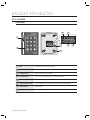
AT A GLANCE
Front/Rear
6
X
Y
Z
[
\
]
^
_
`
lzj
W
lu{
7
5
4
8
zzhTyYWWX
1
LED
Displays the status of the system operation.
2
Keypad
Used to enter the ID/password.
3
2-PIN Connector
Can be connected to the power cable.
4
6-PIN Connector
Can be connected to Wiegand, RS-232 communication cables.
5
8-PIN Connector
Connected to the tamper, LED and buzzer control connection cables.
6
Output Selection Switch
Switch that allows you to select an output from 8 bit, 4 bit Burst and Wiegand.
7
Tamper Switch
Tamper switch.
8
Fixing Screw
Screws for fixing the devices.
6_ product introduction
3
CABLE COLOR SCHEME
❖ 2-PIN Connector
I/O Pins
Signal
Cable Color
DC +12V
Red
Earth-grounding
GND (-)
Black
❖ 6-PIN Connector
I/O Pins
Signal
Cable Color
Wiegand Data Output 0
WIK_DATA0
Green
Wiegand Data Output 1
WIK_DATA1
White
Not Used
Not Used
Orange
RS-232 TX
TX OUT
Purple
Not Used
Not Used
Brown
RS-232-GND
GND
Black
❖ 8-PIN Connector
I/O Pins
Signal
Cable Color
Tamper Switch NC
Tamper NC
Green with White Stripes
Tamper Switch COM
Tamper COM
Gray
LED Control
Red LED Control
White with Red Stripes
LED Control
Green LED Control
Yellow
LED Control
Orange LED Control
Blue with White Stripes
Buzzer Control
BUZZER Control
Blue
Not Used
Not Used
Pink
Not Used
Not Used
Sky Blue
CABLE SELECTION
Item
Cable Type
1
Power (DC12V)
Belden #9409, 18 AWG 2 Conductor, Unshielded
Card/PIN data (Wiegand)
Control Signal (LED,BUZZER)
TAMPER
Belden #9512, 22 AWG 4 Conductor, Shielded
2
RS-232 Cable
Belden #9829, 24 AWG 2-twisted pair, Shielded
3
Belden #9514, 22 AWG 8 Conductor, Shielded
English English _ 7
PRODUCT INTRODUCTION
Power (+12V)
installation and external connection
INSTALLATION
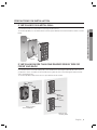
1. Attach the provided wall mount to the wall and drill two 6-32 holes and one 1/2 inch hole on it. (See [Figure 1])
2. Refer to [Figure 2] below on how to secure the wall mount to the wall using the provided screws.
3. Apply each of 5 O-rings to the corresponding point as shown in [Figure 2].
4. Fix the main unit with the wall mount by inserting the main unit’s cables into the center hole and pushing the
main unit towards the wall mount.
O-ring
O-ring
6-32 hole
1.85"(47mm)
1/2” hole
2.05"(52mm)
O-ring
1.55"(39.5mm)
O-ring
1.79"(45.5mm)
6-32 hole
O-ring
1.52"(38.5mm)
1.52"(38.5mm)
3.03"(77mm)
[Figure 1]
J
[Figure 2]
Once the main unit is fixed with the wall mount, it will not be loosened. Please check if the device is operating properly
before fixing it.
If you try to remove the wall mount once it is fixed, the lock parts of the wall mount will break, resulting in a situation where
the whole wall mount must be replaced.
8_ installation and external connection
PRECAUTIONS ON INSTALLATION
IF INSTALLING ON A METAL WALL
Metal
Wall
Z
X
Y
[
\
]
_
`
^
lzj
W
lu{
yYWWX
zzhT
Spacer
Reader
IF INSTALLING MORE THAN ONE READER SIDE BY SIDE OR
FRONT AND BACK
If you install more than one reader side by side or front and back, the read range may be reduced. In this case, if
you present a card to one reader, the other reader may recognize the same card, meaning both readers read the
same card simultaneously.
To avoid this problem, keep at least 20 cm of space between the two readers.
Minimum
20cm
X
Y
Z
[
\
]
^
lzj
_
W
`
lu{
#Reader 1
WWX
zzhTyY
Y
X
Z
[
\
]
^
_
`
W
lzj
Minimum
20cm
lu{
WWX
zzhTyY
#Reader 2
#Reader 1
X
Y
Z
[
\
]
^
BACK TO BACK
<FrontINSTALLATION
and Back>
lzj
_
W
`
lu{
#Reader 2
WWX
zzhTyY
SIDE BY SIDE
<Side by Side>
INSTALLATION
English English _ 9
INSTALLATION AND EXTERNAL CONNECTION
If you install the reader on a metal wall, the read range may be reduced.
To avoid this problem, it is recommended to insert the spacer between the metal wall and the reader as shown
below.
installation and external connection
EXTERNAL CONNECTION
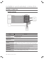
WIRING DIAGRAM
SSA-R2001
Green
Wiegand Data 0 Out
White
Wiegand Data 1 Out
Green with white stripes
X
Y
Z
Tamper Switch Out(COM)
Gray
[
\
]
Buzzer Control In
Blue
^
_
`
lzj
W
lu{
Tamper Switch Out(NC)
CONTROLLER
LED Control In(Red)
White with red stripes
LED Control In(Orange)
PC
RS-232(GND)
Yellow
LED Control In(Green)
RS-232(TX)
Purple
Black
zzhTyYWWX
Blue with white stripes
Red
Black
DC +12V
GND
POWER
Category
Cable Color
Connect the DC+12V to the red line.
Power Supply Unit
Connect GND to the black line.
Connect the green line of the product to the Wiegand D0 input port of the controller.
Wiegand Connection
Connect the white line of the product to the Wiegand D1 input port of the controller.
Enables you to turn on or off the LED indicators.
LED Control
To control green indicator, connect the yellow line to the controller’s output (relay). Connect the blue with
white stripes to control the orange indicator, connect the white with red stripes to control the red indicator.
(see page 12)
Buzzer Control
Enables you to turn on or off the buzzer.
To control the buzzer, connect the blue line to the controller’s output (relay). (see page 12)
Tamper Control
Connect the COM port (gray line) of the product’s tamper switch to GND; connect the NC port (green line
with white stripe) of the tamper switch to the input port of the controller.
RS-232 Connection
Connect to the COM port of the PC. (Connect pin 2 of the DB-9 connector to the purple line; connect the
black of the device (RS-232 GND) to pin 5 of the DB-9 connector)
10_ installation and external connection
initialization
OUTPUT FORMAT
You can adjust the output format of the numeric values from the keypad.
You can select 4/8 bit Burst or 34bit Wiegand.
Adjust the format according to the controller receiving the keypad input.
2. See the table below to make adjustment as needed.
ON
1
2
❖ Output Format
M
SW #1
SW #2
Output Format of Card
Output Format of Keypad
ON
ON
34bit Wiegand + RS-232
34bit Wiegand+RS-232
ON
OFF
34bit Wiegand + RS-232
34bit Wiegand+RS-232
OFF
ON
34bit Wiegand + RS-232
4 bit Burst
OFF
OFF
34bit Wiegand + RS-232
8 bit Burst (Default)
All switches are defaulted to “OFF”.
Before you change the output format, you must disconnected the power.
English English _ 11
INITIALIZATION
1. To change the output format, use the switch on the rear of the
product.
initialization
BASIC OPERATIONS
Initial State (when the power is supplied)
When you apply power to the product, it will sound beep three times before entering Standby with the red indicator
turned on.
Using the card
CX Y
ar
d\
[
Z
]
X
Y
[
Z
\
^
]
i
_
lzj
_
`
lzj
W
lu{
`
^
W
lzj
zzhTzYWWW
Present the card to the product until you hear a beep and the green indicator turns on.
The reader keeps the green indicator turned on while transferring the card data to the
controller.
When it is done, the green indicator turns off and for receiving the next card, the red
indicator stays ON.
zzhTzYWWW
Using the keypad
Hold down the keypad until you hear a beep. The reader transfers the keypad data to the controller.
If the output format of the keypad is the option to 26bit Wiegand, pressing any key of the keypad turns on orange
indicator, and green indicator blinks when [ENT] is pressed after the input. The red indicator stays on after
transferring data to the controller. By default, it is 8-bit burst. Hence, keypad input and pressing [ENT] will blink the
green indicator only when you change the option to 26bit Wiegand.
LED Control
You can control the red, green and orange indicators as necessary.
To control the red indicator, connect the relay output NO port of the controller to the red indicator control input line
(white line with red stripes), and connect the GND line to the COM line. Set I/O of the controller; now you can
control turning on/off the indicators.
You can turn on/off the indicators according to the I/O settings of the controller, which can be applied to various
situations.
For more information about the I/O settings of the controller, refer to the user manual of the controller.
Connect the yellow line for the green indicator, or the blue with white stripes for the orange indicator, to the COM
port of the controller.
Buzzer Control
Connect the buzzer control input line (blue) to the NO port of the controller relay output, and GND to the COM port.
You can configure the I/O settings of the controller so that it beeps. If the product continues to beep, it means that
the buzzer control is working properly.
The controller can use the I/O settings to set the buzzer control so that it sounds an additional beep for authorized
or unauthorized access upon user authentication.
Furthermore, you can make various modifications according to the different I/O settings of the controller.
For more information about the I/O settings of the controller, refer to the user manual of the controller.
Card reading is not available while the buzzer control is sounding the buzzer.
Tamper Control
You can set the signal that you want to output if the device is dismantled forcibly.
Connect the COM port (gray line) of the product’s tamper switch to GND; connect the NC port (green with white
stripe) of the tamper switch to the input port of the controller. If the tamper of the reader operates, the controller
produces an input signal and generates the corresponding output depending on the controller setting.
12_ initialization
output format
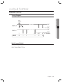
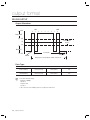
WIEGAND OUTPUT
Timing Diagram
5V
1ms
DATA-0
0V
5V
DATA-1
LOGIC
1
2
3
n-2
n-1
0
1
1
1
0
0V
n *n : 34 or26
0
Data Format (34-bit)
• Bit 1 : Even Parity (bit 2 ~ bit 17)
• Bit 2~Bit33 : 4-byte ID Number
• Bit 34 : Odd Parity (bit 18 ~ bit 33)
English English _ 13
OUTPUT FORMAT
100us
output format
RS-232 OUTPUT
Output Waveform
LSB
+15V
0
1
MSB
0
0
0
0
0
1
0
Space(=0)
+3V
Indeterminate
Region
0V
-3V
Mark(=1)
8 Data Bits
-15V
2 Stop Bits
Start Bit
Data packet corresponding to ASCII character ‘A’
Data Type
M
START (0X02H)
DATA (10 Char)
END (0x03H)
LRC
START(0X02H)
DATA (10 Char)
END (0x03H)
LRC
Check the following settings:
Baud Rate : 9600bps
Data Bit : 8
Parity Bit : None
Stop Bit : 1
LRC : This is the result of XOR operation of each byte from Start to End.
14_ output format
4/8 BIT BURST OUTPUT FORMAT
4Bit Burst Output Format
Binary
Hexa
Keypads
Binary
Hexa
0
0000
0
6
0110
6
1
0001
1
7
0111
7
2
0010
2
8
1000
8
3
0011
3
9
1001
9
4
0100
4
ESC
1010
A
5
0101
5
ENT
1011
B
8Bit Burst Output Format
Keypads
Binary
Hexa
Keypads
Binary
Hexa
0
11110000
F0
6
10010110
96
1
11100001
E1
7
10000111
87
2
11010010
D2
8
01111000
78
3
11000011
C3
9
01101001
69
4
10110100
B4
ESC
01011010
5A
5
10100101
A5
ENT
01001011
4B
English English _ 15
OUTPUT FORMAT
Keypads
troubleshooting
TROUBLESHOOTING
If the product does not function properly, please see the below for trouble shooting.
PROBLEM
SOLUTION
My card is not read properly.
1)
2)
Check the rated voltage specified in the user manual and the catalog.
Ensure that you are using an ISO14443 Type A card.
- Cards of 125 kHz format can not be used. However, the 13.56 MHz card can
not be used if it is of Type B, ISO15693.
(Contact the card retailer regarding the card format.)
3) If the problem persists, contact the nearest customer service for your
assistance.
When I turn on the product, it sounds a
beep with dimly turned on indicator.
1)
2)
3)
The read range (R/R) of the card differs
each time the product reads the card.
1)
2)
16_ troubleshooting
Ensure that you are using a larger-capacity adaptor than specified in the user
manual or the catalog, which should cover the rated current consumption of the
reader. If you are using multiple readers that are connected to one adaptor,
make sure that the adaptor should be large enough to cover the current
consumption multiplied by the reader count.
Even with a large adaptor enough to supply adequate power, if the power cable is
not a dedicated line (such as communication line or UPT cable), or if it’s so long to
cause power loss, you’d better replace it with a dedicated line or reinforce it.
If the problem persists, contact the nearest customer service for your
assistance.
The characteristics of a card are determined by the nature of the coils used and in the
manufacturing process engaged by the card manufacturer. So what you do first is to check
that the cards in use are made by the same manufacturer.
If you are using cards from different card makers, the read range (R/R) differs by the card,
which is the result of normal operation.
If you encounter a different read range for each card that is made by the
same manufacturer, please contact the nearest customer service.
product specifications
PRODUCT SPECIFICATIONS
Item
SSA-R2001
Power / Current
DC 12V / Max.75mA
Reading Time (Card)
30ms
Input Port
2 ea : External LED Control, External Buzzer Control
Output Port
34bit Wiegand, 4/8bit Burst for PIN (Selectable)
LED Indicator
3 LED Indicators (Red, Green and Orange)
Beeper
Piezo Buzzer
Keypad
12 Key Numeric Keypad with Back Lighting
Operating Temperature
-25°C to +50°C
Operating Humidity
10% to 90% Relative Humidity Non-Condensing
Color / Material
Silver with Black/ Polycarbonate
Dimension
(W x H x D(mm))
87.0 x 109.0 x 31.0
Weight
160g
Correct Disposal of This Product (Waste Electrical & Electronic Equipment)
(Applicable in the European Union and other European countries with separate collection systems)
This marking on the product, accessories or literature indicates that the product and its electronic accessories (e.g.
charger, headset, USB cable) should not be disposed of with other household waste at the end of their working life. To
prevent possible harm to the environment or human health from uncontrolled waste disposal, please separate these
items from other types of waste and recycle them responsibly to promote the sustainable reuse of material resources.
Household users should contact either the retailer where they purchased this product, or their local government office, for
details of where and how they can take these items for environmentally safe recycling.
Business users should contact their supplier and check the terms and conditions of the purchase contract.
This product and its electronic accessories should not be mixed with other commercial wastes for disposal.
Correct disposal of batteries in this product
(Applicable in the European Union and other European countries with separate battery return systems.)
This marking on the battery, manual or packaging indicates that the batteries in this product should not be disposed of
with other household waste at the end of their working life. Where marked, the chemical symbols Hg, Cd or Pb indicate
that the battery contains mercury, cadmium or lead above the reference levels in EC Directive 2006/66. If batteries are
not properly disposed of, these substances can cause harm to human health or the environment.
To protect natural resources and to promote material reuse, please separate batteries from other types of waste and
recycle them through your local, free battery return system.
English English _ 17
SALES NETWORK
SAMSUNG TECHWIN CO., LTD.
701, Sampyong-dong, Bundang-gu, Seongnam-si Gyeonggi-do, Korea, 463-400
TEL : +82-70-7147-8740~60 FAX : +82-31-8018-3745
SAMSUNG TECHWIN AMERICA Inc.
1480 Charles Willard St, Carson, CA 90746, UNITED STATES
Tol Free : +1-877-213-1222 FAX : +1-310-632-2195
www.samsungcctvusa.com
www.samsungsecurity.com
www.samsungtechwin.com
SAMSUNG TECHWIN EUROPE LTD.
Samsung House, 1000 Hillswood Drive, Hillswood Business
Park Chertsey, Surrey, UNITED KINGDOM KT16 OPS
TEL : +44-1932-45-5300 FAX : +44-1932-45-5325
P/No. : Z8100239101A