1
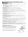
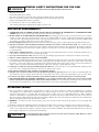
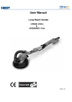
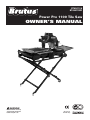
BT65011 &
BT65011IND
Power Pro 1100 Tile Saw
OWNER’S MANUAL
WARNING!
Read and follow all safety
and operating instructions
before using this saw.
*CE relates to
230v-240v only’
BT65011 &
BT65011IND
Power Pro 1100 Tile Saw
WARNING
For your own safety, read
instruction manual before
operating saw.
1. Always wear safety goggles
when cutting.
2. Use splash hood for every
operation for which it can
be used.
3. Disconnect saw before
cleaning or changing blade.
4. Do not use any cutting blade
with openings and grooves.
Use only continuous rim blades.
5. Replace damaged blade
before operating.
6. Do not expose to rain or use
in damp locations.
TABLE OF CONTENTS
SAFETY INSTRUCTIONS FOR TILE SAW . . . . . . . . . . . . . . . . . . . . . . . . . . . . . . . . . . . . . . . . . . . . . . . . . . . . . . . . . . . . . . . .3
WARNING/ELECTRICAL REQUIREMENTS . . . . . . . . . . . . . . . . . . . . . . . . . . . . . . . . . . . . . . . . . . . . . . . . . . . . . . . . . . . . . .4.-5
UNPACKING . . . . . . . . . . . . . . . . . . . . . . . . . . . . . . . . . . . . . . . . . . . . . . . . . . . . . . . . . . . . . . . . . . . . . . . . . . . . . . . . . . . . . . . .5
FEATURES FOR TILE SAW . . . . . . . . . . . . . . . . . . . . . . . . . . . . . . . . . . . . . . . . . . . . . . . . . . . . . . . . . . . . . . . . . . . . . . . . . . . .5
ELECTRICAL & MOTOR SPECIFICATIONS . . . . . . . . . . . . . . . . . . . . . . . . . . . . . . . . . . . . . . . . . . . . . . . . . . . . . . . . . . . . . . . .5
ASSEMBLY & SET UP . . . . . . . . . . . . . . . . . . . . . . . . . . . . . . . . . . . . . . . . . . . . . . . . . . . . . . . . . . . . . . . . . . . . . . . . . . . . . . . .6
BLADE GUARD INSTALLATION . . . . . . . . . . . . . . . . . . . . . . . . . . . . . . . . . . . . . . . . . . . . . . . . . . . . . . . . . . . . . . . . . . . . . . . .6
WATER PUMP INSTALLATION . . . . . . . . . . . . . . . . . . . . . . . . . . . . . . . . . . . . . . . . . . . . . . . . . . . . . . . . . . . . . . . . . . . . . . . . .7
WATER PUMP SAFETY GUIDELINES . . . . . . . . . . . . . . . . . . . . . . . . . . . . . . . . . . . . . . . . . . . . . . . . . . . . . . . . . . . . . . . . . . . .7
SIDE EXTENSION TABLE INSTALLATION . . . . . . . . . . . . . . . . . . . . . . . . . . . . . . . . . . . . . . . . . . . . . . . . . . . . . . . . . . . . . . . .7
SAW OPERATION . . . . . . . . . . . . . . . . . . . . . . . . . . . . . . . . . . . . . . . . . . . . . . . . . . . . . . . . . . . . . . . . . . . . . . . . . . . . . . . . . . . .8
STEPS FOR STRAIGHT CUTS . . . . . . . . . . . . . . . . . . . . . . . . . . . . . . . . . . . . . . . . . . . . . . . . . . . . . . . . . . . . . . . . . . . . . . . . . .8
STEPS FOR DIAGONAL CUTS . . . . . . . . . . . . . . . . . . . . . . . . . . . . . . . . . . . . . . . . . . . . . . . . . . . . . . . . . . . . . . . . . . . . . . . . .8
STEPS FOR PLUNGE CUTS . . . . . . . . . . . . . . . . . . . . . . . . . . . . . . . . . . . . . . . . . . . . . . . . . . . . . . . . . . . . . . . . . . . . . . . . . . .8
STEPS FOR ANGLE CUTS . . . . . . . . . . . . . . . . . . . . . . . . . . . . . . . . . . . . . . . . . . . . . . . . . . . . . . . . . . . . . . . . . . . . . . . . . . . . .9
SAW MAINTENANCE . . . . . . . . . . . . . . . . . . . . . . . . . . . . . . . . . . . . . . . . . . . . . . . . . . . . . . . . . . . . . . . . . . . . . . . . . . . . . . . .9
WATER PUMP MAINTENANCE . . . . . . . . . . . . . . . . . . . . . . . . . . . . . . . . . . . . . . . . . . . . . . . . . . . . . . . . . . . . . . . . . . . . . . . . .9
DIAMOND BLADES . . . . . . . . . . . . . . . . . . . . . . . . . . . . . . . . . . . . . . . . . . . . . . . . . . . . . . . . . . . . . . . . . . . . . . . . . . . . . . . . .10
DO’S & DO NOT’S FOR DIAMOND BLADES . . . . . . . . . . . . . . . . . . . . . . . . . . . . . . . . . . . . . . . . . . . . . . . . . . . . . . . . . . . . .10
TROUBLESHOOTING . . . . . . . . . . . . . . . . . . . . . . . . . . . . . . . . . . . . . . . . . . . . . . . . . . . . . . . . . . . . . . . . . . . . . . . . . . . . . . . .10
-2-
WARNING!
GENERAL SAFETY INSTRUCTIONS FOR TILE SAW
READ THIS OWNER’S MANUAL COMPLETELY AND MAKE SURE YOU UNDERSTAND ALL OF IT’S
SAFETY GUIDELINES.
1.
KEEP GUARDS IN PLACE and in working order.
2.
REMOVE ADJUSTING KEYS AND SPANNERS. Always check to see that keys and adjusting spanners are removed from
tool before turning it on.
3.
KEEP WORK AREA CLEAN. Cluttered areas and benches invite accidents.
4.
DO NOT USE IN DANGEROUS ENVIRONMENT. Do not use power tools in damp or wet locations, or expose them to
rain. Keep work area well lighted.
5.
KEEP CHILDREN AWAY. All visitors should keep a safe distance from the work area.
6.
MAKE WORKSHOP CHILD PROOF with padlocks, master switches or by removing starter keys.
7.
DO NOT FORCE TOOL. It will do the job better and be safer at the rate for which it was designed.
8.
USE THE RIGHT TOOL. Do not force tool or attachment to do a job for which it was not designed.
9.
WEAR PROPER APPAREL. Do not wear loose clothing, gloves, neckties, rings, bracelets, or other jewelry which may get
caught in moving parts. Non-slip footwear is recommended. Wear protective hair covering to contain long hair.
10. ALWAYS USE SAFETY GLASSES. Also use face or dust mask if cutting operation is dusty. Everyday eyeglasses only
have impact resistant lenses, they are NOT safety glasses.
11. SECURE WORK. Use clamps or a vice to hold work when practical. This safety precaution allows for proper tool
operation freeing both hands to operate tool.
12. DO NOT OVERREACH. Keep proper footing and balance at all times.
13. MAINTAIN TOOLS WITH CARE. Keep tools sharp and clean for best and safest performance. Follow instructions for
lubricating and changing accessories.
14. DISCONNECT TOOLS before servicing; when changing accessories, such as blades, bits, cutters, etc.
15. REDUCE THE RISK OF UNINTENTIONAL STARTING. Make sure switch is in the “off” position before plugging in.
16. USE RECOMMENDED ACCESSORIES. Consult the owner's manual for recommended accessories. The use of improper
accessories may increase risk of injury.
17. NEVER STAND ON TOOL. Serious injury could occur if the tool is tipped or if the cutting tool is unintentionally
contacted.
18. CHECK DAMAGED PARTS. Before further use of the tool, a guard or other part that is damaged should be carefully
checked to determine that it will operate properly and perform its intended function – check for alignment of moving
parts, binding of moving parts, breakage of parts, mounting, and any other conditions that may affect its operation. A
guard or other parts that are damaged should be properly repaired or replaced.
19. DIRECTION OF FEED. Feed work into a blade or cutter against the direction of rotation of the blade only.
20. NEVER LEAVE THE TOOL RUNNING UNATTENDED.TURN POWER OFF. Do not leave tool until it comes to a complete stop.
21. Always turn off the power while adjusting the angle for mitre cuts.
22. The cutting table must be in the starting position before adjusting the cutting head, to perform angle cuts.
23. ENSURE THAT THERE IS A CONTINUOUS FLOW OF WATER to both sides of the blade during operation.
24. CHECK DIAMOND BLADES CAREFULLY FOR CRACKS, NICKS, MISSING DIAMOND MATRIX OR OUT OF ALIGNMENT
CONDITION. Replace damaged blades immediately. Do not use damaged blades, which can cause bodily injury.
POSITIONING OF TILE SAW
Illustration 1
(See Illustration 1)
A. To avoid the possibility of the appliance plug or socket getting wet,
position the tile saw to one side of a wall-mounted socket to prevent
water from dripping onto the socket or plug. The user should arrange
a “drip loop” is that part of the cable below the level of the socket, or
connector if an extension cable is used, to prevent water traveling
along the cable and coming in contact with the socket.
B. If the plug or socket does get wet, DO NOT unplug the cable.
Disconnect the fuse or circuit breaker that supplies power to the tool.
Then, unplug and examine for presence of water in the socket.
DRIP LOOP
-3-
WARNING!
•
•
•
•
•
•
•
GENERAL SAFETY INSTRUCTIONS FOR TILE SAW
For Your Own Safety Read Instruction Manual Before Operating Saw
Wear eye protection.
Use blade guard when cutting.
Disconnect saw before servicing, when changing cutting wheels, and cleaning.
Use tool only with continuous rim cutting wheels free of opening and grooves.
Replace damaged blades before operating.
Do not expose to rain or use in damp location.
Turn off the power before adjusting the angle for mitre cuts.
ELECTRICAL REQUIREMENTS
1. CONNECTING TOOL TO POWER SOURCE OUTLET. THIS TILE SAW MUST BE CONNECTED TO A GROUNDED POWER
SOURCE while in use to protect the operator from electrical shock. (Figure 1)
2. IN THE EVENT OF A MALFUNCTION OR BREAKDOWN, grounding provides a path of least resistance for electrical
current to reduce the risk of electrical shock. This tool is equipped with an electric cable having equipment grounding
conductor and a grounding plug. Insert the 3-prong electrical plug into a 3-pole socket that is properly installed and
grounded in accordance with all local codes and ordinances.
3. Do not modify the plug provided if it will not fit the outlet. Have the proper outlet installed by a qualified electrician.
4. Improper connection of the equipment-grounding conductor can result in a risk of electric shock. The conductor with
insulation having an outer surface that is green (with or without yellow stripes) is the equipment-grounding conductor.
If repair or replacement of the electric cable or plug in necessary, do not connect the equipment – grounding conductor
to a live terminal.
5. Check with a qualified electrician or service personnel if the grounding instructions are not completely understood, or
if in doubt as to whether the tool is properly grounded.
6. Use only 3-wire extension cables that have 3-prong grounding plugs and 3-pole sockets that accept the tool’s plug.
7. Repair or replace damaged or worn cable immediately.
8. To avoid the possibility of the appliance plug or socket getting wet, position tile saw to one side of a wall-mounted socket
to prevent water from dripping onto the socket or plug. The user should arrange a “drip loop” in the cable connecting
the saw to a socket. The “drip loop” is that part of the cable below the level of the socket, or the connector if an extension
cable is used, to prevent water traveling along the cable and coming in contact with the socket.
9. If the plug or socket does get wet, DO NOT unplug the cable. Disconnect the fuse or circuit breaker that supplies power
to the tool. Then unplug and examine for presence of water in the socket.
10.Only CE listed extension cables should be used with this product.
11.Improper use of extension cables may cause inefficient operation of your tool, which can result in overheating. Be sure
your extension cable is rated to allow sufficient current flow to the motor. For the proper gauge for your tool, see chart.
12.Do not let your fingers touch the terminals of plug when installing or removing the plug to or from the outlet.
13.THIS TILE SAW MUST BE PROPERLY GROUNDED. If not properly grounded, this power tool can incur the potential
hazard of electrical shock particularly when used in damp locations or in proximity to plumbing. If an electrical shock
occurs, there is the potential of a secondary hazard such as your hands contacting the saw blade.
EXTENSION CABLES
1. Use only extension cables that are intended for outdoor use. These extension cables are identified by a marking
“Acceptable for use with outdoor appliances: store indoors while not in use.” Use only extension cables having an
electrical rating equal to or greater than the rating of the product. Do not use damaged extension cables. Examine
extension cable before using and replace if damaged. Do not abuse extension cables and do not pull on any cable to
disconnect. Keep cable away from heat and sharp edges. Always disconnect the extension cable from the socket before
disconnecting the product from the extension cable.
2. WARNING - To reduce the risk of electrocution, keep all connections dry and off the ground. Do not touch plug with
wet hands.
3. Residual current device (RCD) protection should be provided on the circuit(s) or outlet(s) to be used for the tile saw.
4. Use proper extension cable. Make sure your extension cable is in good condition. When using an extension cable, be
sure to use a cable heavy enough to carry the current your product will draw. An undersized cable will cause a drop in
line voltage, resulting in loss power and overheating.
CAUTION!
To avoid permanent motor damage you must use the correct extension cable. Never use more
than one extension cable at a time.
-4-
WARNING! SPECIFIC SAFETY INSTRUCTIONS
1.
2.
3.
4.
5.
6.
7.
8.
9.
10.
11.
12.
13.
Ensure that the directional arrow marked on the blade corresponds with the rotational direction of the motor.
With the saw disconnected from the power supply, rotate the blade by hand to ensure it is free from obstruction.
Always keep the blade-securing bore and collars clean.
Ensure that the blade-securing bolt is securely tightened.
Never try to cut freehand. Always ensure that the tile to be cut is pressed firmly against the rip guide.
Ensure the material being cut off has sufficient room to move sideways. Failure to do so may result in the off-cut
binding against the blade.
Never cut more than one tile at a time.
Never cut pieces too small that are not held securely against the rip guide, and provide enough space for the hand to
be a safe distance from the blade.
Ensure that the table and surrounding area are clear with the exception of the tile to be cut.
Before cutting a tile piece, let the saw blade run freely for a few seconds. If it makes an unfamiliar sound or vibrates
excessively, switch it off immediately and disconnect it from the power supply.
Let the blade reach full speed before commencing the cut.
Let the blade come to a complete stop before removing any jammed material from around the blade area.
Never allow the blade to run dry. Failure to keep the water tray at the recommended level will result in possible overheating of the diamond blade.
UNPACKING
Open carton from the top.
Top tray contents:
• Front Extension Tray
• 250 mm Diamond Blade
• Upper Frame Wheels
• Water Pump
• Rip Guide
• Cable Collecting Hanger / Tool Caddy with 2 blade spanners and 6 mm Allen Key
• Bag of miscellaneous hardware (includes drain plug, wheel hardware (2), motor frame mounting screws (3),
hardware for mounting tool caddy (2), motor frame locking knob)
• User's Manual
Middle Tray:
• Stand
Bottom Tray:
• Motor Head Assembly
• Saw Frame with Table
• Rear Water Collection Tray
BT65011 & BT65011IND TILE SAW FEATURES
•
•
•
•
•
Removable rear Collection Water Tray
Adjustable cutting head allows plunge cuts and for 22.5° and 45° angle cuts
250 mm diamond blade cuts tile up to 60 mm thick
Maximum rip cut length up to 600 mm tile. Diagonal Cut, up to 457 mm tile
Folded Saw Stand with wheels offers quick set up, as well as easy mobility
ELECTRICAL AND MOTOR SPECIFICATIONS
MODELS
Power Supply
Motor
Max Depth of Cut
Mitre Cutting Angle
Cutting Angle
Package Weight
BT65011
230v - 50Hz
1100w
60mm
22.5° & 45°
0° - 45°
48Kg
BT65011IND
110v - 50Hz
1100w
60mm
22.5° & 45°
0° - 45°
48Kg
-5-
ASSEMBLY & SET UP
CAUTION!
The following is step-by-step installation and operation instruction manual.
Please read the information thoroughly prior to using your tile saw.
A. Stand Setup
1. The Saw and Stand are ready to use. Simply unfold it as shown below.
2. Place the saw frame on the stand and tighten the stand knobs for safety. (See
Diagram 1) You may need to move or remove water tray to easily secure safety knobs to
stand frame.
Diagram 1
B. Installing the Motor assembly
Step 1: Install the Motor Frame Assembly into the Motor Support Arm. (See Diagram 2)
Step 2: Pre-fix the Motor frame red locking knob into the hole provided, as shown.
This knob is used to also fine-tune the alignment of the motor frame assembly.
Step 3: Remove rubber cap to expose hex nuts. Firmly drive the three HEX bolts into
the Motor Support Arm with Allen Key provided and secure the Motor frame
locking knob.
Step 4: Place rubber cap back over hex nuts.
C. Installing the 4 in. Caster and Cable Collecting Hanger
1. Installing Upper Casters: Secure the 4 in. Casters at the two ends of the Base Frame
with HEX bolts & Nuts, as shown. (See Diagram 3)
2. Installing Cable Collecting Hanger/ Tool Caddy: Secure the Hanger onto the Motor
Support Arm with 2 bolts. (See Diagram 4) Place 2 spanners in hanger and place Allen
Key in opening provided.
Diagram 2
D. Diamond Blade Installation
Step 1: When installing the blade, separate the two water feed
hoses inside the blade guard to allow the blade to sit
between them (see diagrams at right).
Step 2: Lift the blade guard and lock in place with the knob holding the blade guard.
Step 3: Hold the blade lock nut with the provided 23 mm spanner and also hold the blade
shaft with the other provided 10 mm spanner. At the same time, please move the
spanners upward to loosen (See Diagram 5) or move downward to tighten (See
Diagram 6) in order to open and close the blade shaft nut & outer flange. Then, attach and secure the blade onto the blade shaft, keeping the inner flange in place.
Place the blade between the two water tubes in the back of
the bladeguard.
Step 4: Replace the blade guard to its original position and tighten knob.
Step 5: To remove or change the blade, just reverse the Installation steps.
Diagram 3
Diagram 4
Diagram 5
-6-
Diagram 6
CAUTION!
Make sure that the directional arrow on the blade
points in the same direction as the arrow marked on
the blade guard fixing plate.
E. Water Pump Installation
Step 1: Make sure the water pump is not cracked or damaged in any way.
Step 2: Attach the end of the tube to the pump nipple and L -shaped water flow at the
back of blade guard.
Step 3: Place the Pump at the location in the water tray that has been designed to secure the
pump during use. (See the Diagram 7).
Step 4: Pour the water into the water tray and make sure the water level is higher than
the pump intake nozzle.
Step 5: Keep the power cable end out of water and plug the power cable into the socket
on the side of the cutting head assembly. The pump is activated by the ON/OFF switch
of the tile saw.
Step 6: Make sure that the water valve connecting the pump to the tubing is in the full
open position.
The following is the water pump safety guidelines.
1. Make sure the pump is connected to grounding-type socket to prevent the electric shock.
2. Make sure the pump and tube is settled steadily to reduce any chance of pump damage.
3. Do not handle the pump by the power cable, with wet hands, or when standing on a
wet surface.
4. Never use the pump for anything other than water, especially petrol, kerosene,
or other combustible or corrosive liquids.
5. Do not attempt to check the pump before disconnecting the power source if the pump fails
to operate.
6. Never operate the pump without water. The pump needs water to cool its own motor.
A dry pump may cause damage or danger.
Diagram 7
Diagram 8
Diagram 9
Diagram 10
F. Installing Rear Water Collection Tray
1. Insert and attach the Back Collecting Tray to the Tank at the corresponding joints.
(See Diagram 8)
G. Installing Extension Table & Side Extension Table
1. Installing Front Extension Table (See Diagram 9):
a. Place the Extension Table in the back of the Main Working Table.
b. Secure the Extension Table with the supplied round cap HEX bolts.
2. Installing Side Extension Table (See Diagram 9):
a. Insert the Side Extension Table tubes into the side tunnels at front and back of
the Main Working Table.
b. Insert the Pins at the ends of Side Extension Table tubes to hold them in place.
-7-
Diagram 11
SAW OPERATION
CAUTION!
1. Do not adjust the saw without first turning off the motor. Failure to do so may result in serious injury to the operator.
2. Always keep the saw clear. Never put things on rail while cutting.
Adjustable Cutting Table Extension
The adjustable cutting extension table is for the support of large format tiles. Users
could adjust front and side extension to desired dimension. (See Diagram 10)
Diagram 12
Motor head height
adjustment
lever
Cutting Tile and Stone
WARNING!
1. Before performing any cuts, check and ensure that the lowest point of the
Blade is no more than 5 mm below the table top. (See Diagram 11)
2. Move the Motor Head Height Adjustment Lever upward (See Diagram 12), to
adjust the head to a proper height below the table. Then lock the lever in the
down position.
Straight Cuts
1. Adjust the 45/90 degree rip guide to 90 degree and position it the desired
distance from the blade. (See Diagram 13)
2. Lean the cutting material against the rip guide and back measurement rail.
3. Loosen the slide tube locking knob. (See Diagram 14)
4. Make a straight cut by pushing the cutting table toward the cutting head.
(See Diagram 13)
Diagram 13
RIP GUIDE
Diagram 14
Diagonal Cuts
1. Adjust the 45/90 degree rip guide to 45 degree and position it the desired
distance from the blade.
2. Position the cutting material against the rip guide and back measurement rail.
3. Loosen the slide tube locking knob. (See Diagram 14)
4. Make a diagonal cut by pushing the cutting table toward the cutting head.
(See Diagram 15)
CAUTION!
Turn off the power before adjusting the tile saw
motor head for plunge cuts or angle cuts.
Plunge Cuts
1. Turn off the power.
2. Position the cutting material against the rip guide and back measurement rail.
3. Loosen the slide tube locking knob. (See Diagram 14)
4. Loosen the Motor Head Adjustment lever on the spring (See diagram 16)
support, to release the cutting head.
5. Bring motor head to the highest position.
6. Push the cutting table to the desired position where the blade is over the tile at
the point you want to start the cut-out.
7. Tighten the slide tube locking knob to a fixed table position.
8. Turn the saw on.
9. Slowly push the blade down into the tile to achieve the plunge internal cut you
desire. (See diagram 17)
10. After each cut, turn the motor off and turn the position of the tile to achieve
rectangle or square cut-outs.
-8-
Diagram 15
RIP GUIDE
Diagram 16
Angle / Mitre Cuts
WARNING!
Diagram 17
The saw is adjustable to three positions (0°, 22.5 °or 45°).
Any other angle cut will damage the work table.
Step 1: Turn off the power.
Step 2: Position the cutting table in its farthest back position and lock with slide tube
locking knob.
Step 3: Loosen the Angle Adjustable Knob on the Angle Support Arm (See
Diagram 18), found at the back of the motor head, to adjust the guide by tilting
the head (See Diagram 19) to 22.5° or 45°angles. (Make sure the blade aligns
with the angle slot provided on the cutting table.)
Step 4: Tighten the Angle Adjustable Knob when the cutting head is positioned on the
desired angle.
Step 5: Turn on the power and make angle cuts by pushing the cutting table toward
the cutting head
Diagram 18
SAW MAINTENANCE
CAUTION!
Do not service, clean, or maintain the saw without first turning
off the motor and unplugging the saw from its power source.
Failure to do so may result in serious injury to the operator.
For the long life and best performance of saw:
1. Always clean the saw after every use.
2. Wipe off all exterior surfaces and keep the cutting table clean and free of all debris.
3. Wipe off both the guide bars and the rollers of the cutting table.
4. Keep ventilation slots of the motor clean to prevent overheating.
5. Always check the blade for cracks or signs of damage.
6. Clean the Side Extension Table tubes after each use.
Diagram 19
NEVER attempt to service the internal parts of the motor. Contact our company’s
Customer Service Department for any motor function problems or failures.
WATER PUMP MAINTENANCE
CAUTION!
Diagram 20
Disconnect the power before maintain the pump.
1. Disassemble the water pump to see if any cracks or dirt are inside. (See
Diagram 20)
2. Check if the water tubing is clogged where the water cannot flow. Clear the tubing
with warm water.
3. Make sure pump is plugged in during use.
4. Make sure the in-take sponge filter is cleaned after each use.
5. Pump clean/ fresh water for one minute through the water pump and the blade
guard to prevent waste build-up and clogging.
Diagram 21
Do not run the pump without water.
Moving the saw
1. Before moving the saw, be sure to tighten the Slide Tube Locking Knob at the Main
Working Table sliding tube, to prevent Main Working Table from sliding randomly
during transport. (See Diagram 21)
2. This saw includes two sets of wheels:
• Use the wheels attached to the saw, when moving the saw longer distances to
the job site. (See Diagram 22) The stand folds up for easy transport, as well.
(See Diagram 23)
• Use the stand with the locking wheels, when moving your saw short distances,
around the job site.
-9-
Diagram 22
DIAMOND BLADES
1. Use only 250 mm wet continuous rim diamond blade with this saw.
2. Bore size is 16 mm Please choose the right size to fit the inner flange.
3. Do not use wood sawing blade, or other blades not suitable for ceramic, porcelain
or stone. Severe body injury or the saw damage may occur.
DO & DON'TS For Diamond Blades
DO'S:
1. Inspect blades daily for cracks or uneven wear. Discard cracked, chipped
or bent blades!
2. Always use manufacturers’ recommendation for matching the right blade with the
right material being cut.
3. Inspect the bore shaft for uneven wear before mounting the blade.
4. Always use blades with the correct bore size on a compatible bore shaft 16 mm.
5. Ensure the blade is mounted with the rotation arrow in the proper direction and is
securely tightened with a spanner.
6. Always wear the proper safety equipment at all times when operating the saw.
7. Always have a continuous flow of water on both sides of the blade before cutting
any material.
DONT'S:
1. Do not
2. Do not
3. Do not
4. Do not
5. Do not
6. Do not
operate the saw without all safety guards in position.
operate the saw with blades larger or smaller than 250 mm.
cut dry with blades marked “Use Wet”.
exceed maximum RPM recommended by the blade manufacturer.
force the material into the blade. Let the blade cut at its own speed.
cut material not recommended by the blade manufacturer.
TROUBLESHOOTING
OVERHEATING OF SAW:
A. Turn saw off and let it rest until motor is cool to the touch.
B. Check and clean the ventilation slots, removing blockage and dirt.
THE SAW DOES NOT START:
A. Confirm power cable is properly plugged in.
B. Check power source voltage is 230v-240v from outlet.
C. Switch is at the “ON” position.
Water is not flowing through the water pump:
A. Make sure water in tray is high enough to clear the intake nozzle.
B. Make certain the water valve connecting the pump to the tubing is in
the “ON” position.
C. Check water hose for connection or clogs.
D. Confirm power cable is properly plugged in.
E. Check for excess debris on intake filter.
CUTTING TABLE IS NOT SLIDING SMOOTHLY:
A. Thoroughly clean Guide Rails.
If problem continues, contact:
Q.E.P.
Everest Road,
Lytham St Annes, Lancashire.
FY8 3AZ
Tel: 01253 789 180
- 10 -
Diagram 23
NOTES
______________________________________________________________________________
______________________________________________________________________________
______________________________________________________________________________
______________________________________________________________________________
______________________________________________________________________________
______________________________________________________________________________
______________________________________________________________________________
______________________________________________________________________________
______________________________________________________________________________
______________________________________________________________________________
______________________________________________________________________________
______________________________________________________________________________
______________________________________________________________________________
______________________________________________________________________________
______________________________________________________________________________
______________________________________________________________________________
______________________________________________________________________________
______________________________________________________________________________
______________________________________________________________________________
______________________________________________________________________________
______________________________________________________________________________
______________________________________________________________________________
______________________________________________________________________________
______________________________________________________________________________
______________________________________________________________________________
______________________________________________________________________________
______________________________________________________________________________
______________________________________________________________________________
______________________________________________________________________________
______________________________________________________________________________
______________________________________________________________________________
______________________________________________________________________________
______________________________________________________________________________
______________________________________________________________________________
______________________________________________________________________________
______________________________________________________________________________
______________________________________________________________________________
- 11 -
Made in China
Brutus® is a registered trademark of Q.E.P. Co., Inc.
Q.E.P. Co., UK Ltd, Everest Road, Lytham St Annes, Lancashire. FY8 3AZ England
Tel. +44 (0) 1253 789 180
www.qep.com
S0910-5913