1
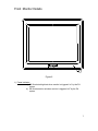
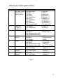
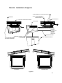
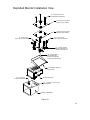
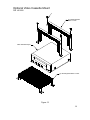
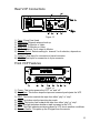
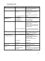
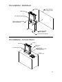
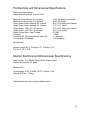
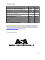
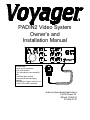
PADIN2 Video System
Owner’s and
Installation Manual
Features:
-Audio in/out connectors
-Full metal chassis
-Two microphone input capability
with
individual gain controls
-Internal and external paging
capacity
-Designed to “trigger”monitors “on”
when VCP mode is selected
Audiovox Specialized Applications
23319 Cooper Dr.
Elkhart, IN 46514
219-264-3135
Table of Contents
Page Number
Contents and System Components
Installation Guide
1
2-3
Front PADIN2 Features
4
Rear PADIN2 Features
5
PADIN2 Harness Details
6
Front Monitor Features
7
Rear Monitor Features
8
Wire Color Code and Function
9
Bus Harness Layout
10
Monitor Installation Diagram
11
Exploded Monitor Installation View
12
Speaker Connections
13
Optional Video Cassette Mount
14
VCP Rear Connections
15
Troubleshooting Guide
16
PADIN2 Wall or Console Installation
17
PADIN2 and Monitor Electrical and Dimensional Specifications
18
System Components
PADIN2
Wiring Harnesses
Microphone
1
Installation Guide
Wiring Precautions
1) To prevent battery discharge or component damage:
a) Connect the monitors to 12VDC or 24VDC “Ignition Hot Only”
b) Connect PA/Video Cassette Player and Radio to 12V “Ignition Hot Only”
c) All monitors have a “trigger” lead (18G Blue/White in monitor pigtail), which is
connected to PA.
2) Harness Installation
a) For ease of installation, route all cables with vehicle OEM harness.
This will reduce the risk of damage to the wiring system.
b) Route enclosed harness as indicated in Figure 8. This harness
provides individual electrical drops for connection to Power, VCP,
Front Radio, PA, and Monitor#1.
c) The installer is responsible for routing the Monitor power, Monitor
Trigger, Speakers, Video in/out wires to each location determined by
installer/customer.
NOTE: We recommend that the installer make the appropriate video connections
with the supplied Video Cable. This cable has been specifically chosen for this
application. When connecting speakers to this system, please use the attached
diagram (Fig. 11). Be sure 4Ω impedance load is supplied to the PA. This will
provide maximum sound pressure level and appropriate signal loading for the
PA.
3) Radio Installation
a) Install radio per packaged instructions.
b) Connect LR+ and RR+ of radio per the following color description:
1. Yellow/Red from harness to RR+ of radio
2. Yellow from harness to LR+ of radio
NOTE: Negative connections are not required on the input.
4) VCP Installation
a) VCP can be mounted in the following methods:
1. Obtain ASA “soft mounting kit” P/N 1401250. (Fig. 12)
2. Double side tape, minimum thickness 0.187” dual lock Velcro applied to
bottom of VCP.
b) Connect the Video out (yellow terminal) to male RCA connector
(color coded yellow).
c) Connect the Audio out (white terminal) to male RCA connector
(color coded white).
d) Connect the 2.1mm DC jack to power input of VCP. Be sure this
line is infused with an in-line 3-Amp Blade or Glass Fuse.
5) PA Installation
The PA should be mounted in a DIN sized opening on the vehicle’s dash. This
location will allow the driver access to controls.
6) MIC Installation
a) MIC extension plugs into the back of the PADIN2 unit.
b) MIC itself plugs into MIC extension cable.
c) Adjust MIC gain controls to user preference.
7) Monitor Installation (Fig. 10)
a) Locate position of monitor(s). Determine rotation and tilt of monitor prior to
drilling holes.
b) After mounting holes are located, drill four 7/16” holes.
c) Depending on the construction of the luggage rack, two mounting plates may be
required to support monitor assembly. (Fig. 9 & 10)
2
Installation Guide (cont.)
d) Depending on the angle of the luggage rack, a 10°wedge base may be required
to keep monitors parallel to the floor. (Fig. 10)
e) Drop four 5/16” grade 8 mounting bolts through mounting holes. (from top of
luggage rack down)
f) Place a mounting plate washer, lock washer, and nut on bolt and tighten to 100
In.lbs. This will provide monitor with a solid mounting base.
g) Place a nut, lock washer, and washer on bolt prior to putting mounting bracket in
place. This will aid in setting the optimal viewing angle.
h) If required, place the wedge base in position. Place mounting bracket in position
and assemble washer, lock washer, and nut to hold bracket in position.
i) Slide monitor into position and hand tighten two ¼-20x1” bolts to hold monitor in
position. Adjust hardware combination to achieve optimal viewing position.
(Fig.10)
j) Connect video in/out (6-pin connector) and power (4-pin pigtail). Cut looped
wire. Splice two 14G orange from harness to one 14G orange from pigtail,
connect two 14G black from harness to one 14G black from pigtail, connect two
18G blue/white from harness to 18G blue/white of pigtail.
k) Install remaining ¼-20 grade 8 bolts and tighten all four to 100 in. lbs.
l) Clean four tabs of mounting bracket with a 70% solution of isopropyl alcohol.
m) Place two 1” x 1” and 1”x 2’pads of “dual lock”velcro on mounting bracket. (Fig.
10)
n) Place padded shroud over monitor assembly and locate position of mating velcro
pad. If a 10°wedge base is used, be sure shroud is flush to all edges prior to
attaching velcro.
o) Clean internal surface of padded shroud with 70% isopropyl alcohol.
p) Place two 1” x 1” and 1”x 2” pads of “dual lock” velcro on padded shroud (as
located in step n) above.
q) If necessary place 10°wedge base over monitor/bracket assembly and push four
pads of velcro together, being sure all four pads are fully engaged with pads on
monitor.
r) Repeat above steps for each additional monitor location.
SWITCHCRAFT A4F
CONNECTOR
PTT Green
MIC (+) White
MIC (-) Black
PTT Red
Microphone Pin View
Figure 1
3
Front PADIN2 Features
Figure 2
1) Bass Control Knob- Turn knob clockwise to increase bass and counterclockwise to
decrease bass.
2) On/Off Knob- This knob turns the PADIN2 on and off.
3) Treble Control Knob- Turn knob clockwise to increase treble and counterclockwise
to decrease treble.
4) Radio- Pressing this button switches between PADIN2 and radio.
5) VCP- This button switches the PADIN2 to VCP and also triggers the monitor.
Indicator light will be lit when this function is selected.
6) PA- This button switches the PADIN2 to the PA/MIC system. The indicator light will
be lit when this function is chosen.
7) Paging Mode- This button is used to page over the PA system. The indicator light
will be on when this button is depressed. An additional push of this button will toggle
back and forth between the internal and external paging system.
VCP Controls
NOTE: For these controls to function, the IR repeater/emitter must be
installed over the IR window on the VCP.
8) FFWD- This button fast forwards the tape in the VCP.
9) Play- This button starts the tape playing in the VCP.
10) VCP Power- This button powers the VCP on and off.
11) Stop- This button stops the tape when it is in “play”or another mode.
12) REW- This button will rewind the tape when it is in “play” or “stop” mode.
13) Replay- This button will stop the tape and rewind back to the beginning of the tape
and resume play mode.
Switchcraft D4M Connector
Philmore T609CB Connector
Microphone Cable Adapter
Figure 3
4
Rear PADIN2 Features
Ext. Spkr (-)
R Int. Spkr (-)
2
3
4
Radio Input R (+)
Radio Input L(+)
Audio From VCP (+)
R Int. Spkr (+)
Ext. Spkr (+)
5
+12V
6
7
1
L Int. Spkr (-)
L Int. Spkr (+)
IR (+)
IR (-)
Monitor Trigger
Ground
Audio From VCP (-)
Figure 4
1) MIC Gain- These controls are accessed through the control in rear. The
potentiometer marked GAIN1 sets the level for the MIC jack, and GAIN2 sets
the level for the second MIC jack. These adjustments will be required to
match audio levels of the other sources.
To adjust:
a) Turn the PADIN2 to the “on”position and turn the volume control to half
volume and select Video or Radio on the source select control.
b) Be sure the video or radio source is operational to obtain a reference
level.
c) Connect the hand-held MIC to rear panel.
d) Key the microphone and adjust level to existing audio level produced
by the selected source. Clockwise increases the audio level and
counterclockwise will decrease the level.
2 & 3) Microphone 1 and 2- Microphone input plus adapter will allow operater to
use most available microphones, the appropriate Gain control
potentiometer must be preset per the above instructiions. See Fig. 1 for
microphone and pinout.
4) Speaker Out- This connection goes to both right and left internal and external
speakers. See Fig. 11 for speaker connections
5) Mounting Lugs- Used to level out the radio when mounting.
6) Power- Connector (Amp P/N 172167-1) mates to Amp 171637-1. See wire
color Code and harness layout . (Table 1 and Figure 8)
7) Audio In- Supplies audio from VCP, monitor and radio.
5
PADIN2 Harness Details
IR LED: Clean the IR Receiver
window on the front of the VCP,
remove adhesive backing and
apply IR LED to IR window on
the face of the VCP.
IR Harness
Speaker Out Harness
Power Monitor Trigger Out Harness
Connects to monitor power control in
Audio Input Harness
Figure 5
6
Front Monitor Details
1
Figure 6
1) Power Indicatora) Will illuminate bright red when monitor is triggered “on”by the PA
system.
b) Will illuminate dim red when monitor is triggered “off”by the PA
system.
7
Rear Monitor Features
Video In (-)
12-24VDC
2
Video Out (+)
3
1
Video In (+)
4
Video Out (-)
Figure 7
Chassis Ground
Trigger From PA 12V
Monitor Operating Controls
1) Picture Selectora) “Press”left most button to trigger “On screen display.” Order of
control: Contrast, Brightness, Tint and Color.
b) Use the “+”and “-“buttons to increase or decrease the setting to
achieve the uniformity of each monitor in your application.
2) Video Input/Output Connectora) Mating Connector: Amp P/N 172168-1, Mating terminal: Amp P/N
171637-1.
b) See Table 1 and Figure 8 for customer insertion view and harness
color code.
3) Monitor Power Controla) Mating connector: Amp P/N 172167-1, mating terminal: Amp P/N
171637-1.
b) See Table 1 and Figure 8 for customer insertion view and
harness color code.
4) Monitor Fuse*Replacement fuse should be a 5 Amp automotive glass fuse* Do
not replace with a higher or lower rated fuse. An over rated fuse will
allow excessive current draw to damage the monitor. An under
rated fuse will fail during power up or cause heat damage to the fuse
holder or monitor (depending on the rating of the fuse).
8
Wire Color Code and Function
Number
1
Function
PA- Video / Audio
Switching and
Volume control
2
Front radio
Lt. Rear (+)
Rt. Rear (+)
VCP
3
4
Input Power/
Ground
5
Monitor
6
External Speaker
7
Passenger Side
Speaker
Driver Side
Speaker
8
Wire Color/ gauge
18G Blue/White
14G Red
14G Black
18G Green
18G Green/Black
18G Gray
18G Gray/Black
18G Pink
18G Pink/Black
18G 2-Shieled cable
18G Yellow
18G Yellow/ Red
16G Red
16G Black
18G Shielded Audio cable
18G Shielded Video cable
16G Red
16G Black
16G Orange
16G Orange
16G Black
18G Shielded Video cable
18G Shielded Video cable
18G Pink
18G Pink/ Black
18G Green
18G Green/ Black
18G Gray
18G Gray/ Black
12VDC Out
+12VDC
Chassis Gnd
Rt Speaker (+)
Rt Speaker (–)
Lt Speaker (+)
Lt Speaker (-)
Ext. Speaker (+)
Ext. Speaker (-)
VCP Audio Out
Lt. Rear (+)
Rt. Rear (+)
12VDC
Chassis Gnd
12VDC
Chassis Ground
24VDC
12 to 24VDC
Chassis Gnd
(from VCP)
(to 2nd, 3rd, 4th, etc.)
Speaker (+)
Speaker (-)
Speaker (+)
Speaker (-)
Speaker (+)
Speaker (-)
Table 1
9
Harness Layout
7
7
5
8
7
8
7
6
8
5
3
2
8
5
5
1
1
4
Optional PA location
Figure 8
10
Monitor Installation Diagram
COMPRESSION PLATES (OPTIONAL)
5/16 x 18 UNC GRADE 8
CARRIAGE BOLTS
HARNESS
LUGGAGE RACK
1" x 1" VELCRO STRIPS ON 2-SIDES
9" MONITOR
WEDGE BASE
MOUNITNG BRACKET W/BOLTS
12-24VDC
CHASSIS GND
TRIGGER
VIDEO IN
VIDEO OUT
MONITOR PIGTAIL
1/4X20 BOLT GRADE 8
4 PLACES
1" x 2" VELCRO STRIPS
ON FRONT AND BACK
VINYL WRAPPED SHROUD
DRIVER SIDE
PASSENGER SIDE
Figure 9
11
Exploded Monitor Installation View
(4) - 5/16x18 UNC Grade 8
Carriage Bolts (P/N 8001500)
Compression (Crush) Plate
(Optional) (P/N 1400003)
Compression (Crush) Plate
(Optional) (P/N 1400003)
(2) - 1 X 2 Dual Lock
Velcro Tape (P/N 8001508)
(2) - 1X1 Dual Lock
Velcro Tape (P/N 8001508)
(4) - 1/4X20X1 Grade 8
Bolts (P/N 8001501) and
Washers (P/N 8001503)
(12) - 5/16X18 Grade 8
Nuts (P/N 8001030),
Washers (P/N 8001502)
Lockwashers (P/N 8001504)
10° Wedge Base (Optional)
(P/N 1400150)
(2) - 1X1 Dual Lock
Velcro Tape (P/N 8001508)
Monitor (P/N BV0901)
(2) - 1 X 2 Dual Lock Velcro Tape
(P/N 8001508)
Shroud (P/N RPVBSH91)
Figure 10
12
Speaker Connections
To obtain optimum sound pressure level, and compatible load, please use the
speaker connection methods illustrated.
18 GRN(+)
PASS. SIDE SPKR
18 GRN/BLK (-)
18 GRY (+)
4Ω or 8Ω
DRIVER SIDE SPKR
18 GRY/BLK(-)
18 GRN(+)
PASS. SIDE SPKR
18 GRN/BLK (-)
4 Ohm only
18 GRY (+)
DRIVER SIDE SPKR
18 GRY/BLK(-)
18 GRN(+)
PASS. SIDE SPKR
18 GRN/BLK (-)
18 GRY (+)
4 Ohm only
DRIVER SIDE SPKR
18 GRY/BLK(-)
18 GRN(+)
PASS. SIDE SPKR
18 GRN/BLK (-)
4Ω or 8Ω
18 GRY (+)
DRIVER SIDE SPKR
18 GRY/BLK(-)
Figure 11
13
Optional Video Cassette Mount
P/N 1401250
(2) Clamp Brackets
With 1" Foam
Video Cassette Player
(1) Mounting Base With 1" Foam
Figure 12
14
Rear VCP Connections
Figure 13
1)
2)
3)
4)
5)
6)
Fuse- 2 Amp Fuse Used
Antenna In- External antenna hook-up
Video Out- To Monitor or Video
Audio Out- To Moinitor or Video
RF Out- Channel 3 or 4 output to Monitor
Channel Select- Selects setting for channel 3 or 4 selection, depends on
area you live in.
7) Power In- Dual input for connection to barrel connector
8) DC 12V- Dual input for connection to 4-pin connector
Front VCP Features
Figure 14
1) Power- This button powers the VCP “on” and “off”.
2) Stop/ Eject- This button stops the tape and a second push ejects the VCP
tape.
3) REW- This button rewinds the tape from either “play” or “stop”.
4) Play- This button sets the tape into play mode.
5) FFWD- This button fast forwards the tape from either “play”or “stop”.
6) CST- This light indicates whether a tape is present in the VCP.
7) DEW- This light indicates moisture present in VCP due to weather conditions.
8) Remote Sensor- This picks up the IR signal from the remote.
15
Troubleshooting
Symptom
PA will not power up
Cause
No 12V power to the PA
Monitors will not power up
No 12-24V power to
monitors
Video screens have
interference
No audio from speakers
No 12V trigger voltage from
PA to monitor
Poor connections
Check that PA is set to VIDEO
mode
Check that PA has 12V power
Check crimp connections at monitor
Bad VHS tape
Dirty heads on VCP
Speakers not connected
Try new VHS tape
Clean VCP heads
Measure resistance between gray
and gray/black wires (should be
between 2-16Ω)
Measure resistance between green
and green/black wires (should be
between 2-16Ω)
Volume on PA turned down
Turn volume control up and check
audio from VCP to PA and radio to
PA
Check VCP 3-amp fuse
Check for 12V at VCP power
connector
Turn MIC volume up
Adjust MIC GAIN controls up
(located behind recessed holes on
front panel of PA)
Adjust PA master volume up
VCP will not power up
No 12V power to VCP
No audio when MIC is
keyed (other sources OK)
MIC volume control turned
down
VCP audio has alternator
whine or hum
Radio has alternator whine
or hum
Possible Solution
Check for front panel fuse.
Check for 12V power to PA
PA not turned on
Check monitor 5-Amp fuse
Check for 12V to 24V power at
monitor pigtail
MIC defective
Replace MIC
PA defective
Ground loop between PA
and VCP
Power source “dirty”
Replace PA
Install NF-20 isolation transformer
on audio output of VCP
Install NF-12 noise filter on power
leads of PA
Ensure that PA is securely grounded
to metal frame of chassis, free from
paint, oil, dirt, etc.
PA has poor ground
connection
16
PA Installation- Wall Mount
Lower Left Side
Of Driver's Seat
PADIN2
DIN Sleeve
(4) #8 Self-Tap Screws
Wall Can Mounting Plate
(Use DIN Sleeve)
Wall Mount Box
P/N 1400002
(4) #10 Self-Tap Screws
___________________________________________
PA Installation- Console Mount
DIN Sleeve
PADIN2
Driver's Side
Console
(4) #8 Self-Tap Screws
P/N 8014005
Wall Can Mounting Plate
(Use DIN Sleeve)
Cut Out
7 1/4" x 2 3/16"
17
PA Electrical and Dimensional Specifications
Electrical measurements:
*Measurements made at Vcc=14.7VDC
Maximum Output Power: 4Ω , Internal
Maximum Output Power: 4Ω , External
Output Power before clipping: 4Ω , Internal
Output Power before clipping: 4Ω , External
Output Power, THD 10%: 4Ω Internal
Output Power, THD 10%: 4Ω External
Signal / Noise Ratio, Input Floated
Crosstalk
Current Draw, 1/8 rated power all inputs:4Ω
Current Draw, (Quiescent)
11.8V (35 Watts) per channel
10.0V (25 Watts)
8.8V (19.4 Watts) per channel
7.5V (14.1 Watts)
9.5V (22.6 Watts) per channel
8.8V (19.4 Watts)
67.5dB
-53dB
1.1 Amperes
0.40 Amperes
Dimensional:
Overall: Length: 8.75” X Height: 2.81” X Depth: 7.63”
Cut Out: 7.25” X 2.38”
Monitor Electrical and Dimensional Specifications
Input Voltage: 12 to 24VDC Switch Mode Power Supply
Power Consumption: 34 Watts
Dimensional:
Overall Height: 8.20” X Width: 10.25” X Depth: 11.84”
Weight: 30.0 lbs. (13.6 kg)
*Specifications are due to change without notice
18
Accessory List
Description
AVT-988 9” Color Television with Remote (12V)
AVT-597 5” Color Television with Remote (12V)
AVT-1498 13” Color Television with Remote (12V)
AVP-7000 Video Cassette Player (12V)
BPA-501-12 4 Amp Adapter for use with AVT-988 9”
and AVT-1498 13”Televisions
AC2A- 2 Amp Adapter for use with AVT-597 5”TV
and AVP-7000 Video Cassette Player
Unified Remote Control
VAC-21- 12 Volt Corded Vacuum
AVF-1 12 Volt Rechargeable Flashlight
HP-175 Headphones with Pivoting Ear Cup
HP-275 Headphones with Volume Control on Cord
HP-375 Studio Quality Headphones
Part Number
AVT988
AVT597
AVT1498
AVP7000
0891412
Price
$320.00
$320.00
$350.00
$270.00
$45.00
0891436
$35.00
0892325
VAC21
AVF1
HP175
HP275
HP375
$45.00
$35.00
$25.00
$11.75
$16.00
$14.00
Unlike household electronics, all of our products have been specifically designed
and tested for the mobile environment and are only available through ASA. To
order any of these products, please contact Audiovox Specialized Applications at
www.entertainment-to-go.com or 800-688-3135.
*Prices subject to change
19