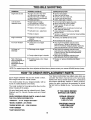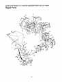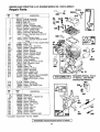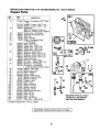
1
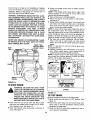
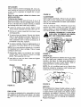
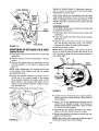
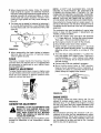
OWNER'S
MANUAL
MODELNO.
247.795950
i
z
CRRFTSMRN®
Caution:
ReadandFollow
AllSafetyRules
andInstructions
BeforeOperating
This Equipment
5 HORSEPOWER
3 CUTTING STAGE
MULCHING AND BAGGING
CHIPPER-SHREDDER
Assembly
Operation
Customer Responsibilities
Service and Adjustment
Repair Parts
SEARS,ROEBUCKAND CO., HoffmanEstates, IL 60179 U.S.A.
Printed in U.S.A.
770-8473H
1/95
S, .FETY RULES
WARNING:
TO REDUCE
SAFETY
INSTRUCTIONS.
THE PCTENTIAL
FOR ANY INJURY,
FAILURE
TO COMPLY
WITH THE
COMPLY WITH
INSTRUCTIONS
THE FOLLOWING
I
MAY RESULT
IN
I
I&,PERSONALINJURY.
TRAINING
• Read this owner's manual carefully in its entirety before
attempting to assemble or operate this machin_. Be completely familiar with the controls and the proper Jse of this
machine before operating it. Keep this manua in a safe
place for future and regular reference and fc" ordering
replacement parts.
• Children must never be allowed to operate this e,luipment.
• No one should operate this unit while intoxicated or while
taking medication that impairs the senses or re_Lctions.
• This equipment should never be operated in t_e vicinity
of children, pets or other persons.
• Never run your machine in an enclosed ar,,,a as the
exhaust from the engine contains carbon mono_ ida, which
is an odorless, tasteless and deadly poisonous g is.
• Never place your hands or any part of your bod_' or clothing inside the feeding chamber, discharge chul_, or near
any moving part while the machine or engine is "unning.
• If it is necessary for any reason to inspect or repair the
feeding chamber or any part of the machine wh_ re a moving part can come in contact with your body c" clothing,
stop the machine, allow it to cool, disconnect the spark
plug wire from the spark plug and move it awa, r from the
spark plug before attempting such inspection or r ;pair.
PREPARATION
• Wear safety glasses provided with your unit wh le operating the chipper-shredder to prevent injury from _ny material which may be ejected out of the openings.
• Wear proper apparel. Avoid wearing loose fittin!l clothing.
Wear gloves when handling material.
• HANDLE GASOLINE WITH CARE as it is an _xtremely
flammable fuel.
• Check the fuel before starting the engine. Do ilot fill the
fuel tank indoors, while the engine is running, el while the
engine is still hot. Turn the unit off and let the engine cool
before refueling.
• Fuel your chipper-shredder
in a clean arez.. Do not
smoke while refueling.
• Fuel tank cap must be secure at all times excE:pt during
refueling.
• Avoid spilling gasoline or oil. Wipe the unit cle]n of any
spilled fuel or oil.
• Store fuel and oil in approved containers, away from heat
or open flame, and out of reach of children.
• This machine should be operated only upon a lew _1surface.
• Assure that all screws, nuts and bolts and other fasteners
are properly secured.
OPERATION
• When feeding shreddable material into this e_luipment,
be extremely careful that pieces of metal, rock_, bottles,
cans or other foreign objects are not included. Personal
injury or damage to the machine could result.
&
•
•
•
•
•
•
•
•
•
•
•
if the cutting mechanism strikes any foreign object or if
your machine should start making an unusual noise or
vibration, immediately stop the engine, disconnect the
spark plug wire from the spark plug and move it away
from the spark plug. Allow the machine to stop and take
the following steps:
Inspect for damage.
Replace or repair any damaged parts.
Check for any loose parts and tighten to assure continued safe operation.
The engine must be kept clean of debris and other accumulations.
Do not allow an accumulation of processed material to
build up in the discharge area as this will prevent proper
discharge and can result in kick-back from feed opening.
Never place your hands or any other part of your body or
clothing inside the feeding chamber, discharge chute or
near any moving part while the engine is running.
Keep all guards and deflectors in place and in good working condition to assure continued safe operation.
Always stand clear of the discharge area when operating
this machine.
Keep your face and body back from the feed opening to
avoid accidental bounce back of any material.
Do not over-reach. Keep proper balance and footing at all
times.
The engine governor settings on your machine must not
be altered, changed, or tampered with. The governor
controls the maximum safe operating speeds and protects the engine and all moving parts from damage
caused by overspeed.
Do not transport machine while engine is running.
Do not operate engine if air cleaner or cover directly over
carburetor air intake is removed, except for adjustment.
Removal of such parts could create a fire hazard.
MAINTENANCE AND STORAGE
• When this equipment is stopped for servicing, inspection,
storage or to change an accessory, make sure the spark
plug wire is disconnected from the spark plug and moved
away from the spark plug. The machine should be
allowed to cool down before making such inspection,
adjustments, service, etc. Maintain your machine with
care and keep it clean for the best and continued safe
operation.
• Do not use flammable solutions to clean the air filter.
• When not in use, your machine should be stored out of
the reach of children. Keep where gasoline fumes will not
reach an open flame or spark. For long periods of storage, refer to the "Storage" section of this manual.
L]OK FOR THIS SYMBOL TO POINT OUT
II_IPORTANT SAFETY PRECAUTIONS. ITI
lYEANS--ATTENTION!!! BECOME ALERT!!!]
Y Z)URSAFETY IS INVOLVED.
I
]
CONGRATULATIONS
on your purchase of a Sears
Craftsman Chipper-Shredder.
It has been designed, engineered and manufactured to give you the best possible
dependability and performance.
Should you experience any problem you cannot easily remedy, please contact your nearest Sears Service Center/
Department in the United States. We have competent, welltrained technicians and the proper tools to service or repair
this unit.
Please read and retain this manual. The instructions will
enable you to assemble and maintain your chipper-shredder
properly. Always observe the "SAFETY RULES."
MODEL
NUMBER
5.0
Displacement:
12.57 cu. in.
Engine Oil:
API Classification
SAE 30
(1-1/4 Pints)
SG or SH
Fuel Capacity:
1 Gallon
(Unleaded)
Champion
J19LM (or
Equivalent)
247.795950
SERIAL
NUMBER
Magnetron ® Ignition Air Gap:
DATE OF
PURCHASE
Tire Pressure:
YOU SHOULD RECORD BOTH SERIAL NUMBER AND
DATE OF PURCHASE AND KEEP IN A SAFE PLACE
FOR FUTURE REFERENCE.
CUSTOMER
•
Horsepower:
Spark Plug (Gap .030 in.):
THE MODEL AND SERIAL NUMBERS WILL BE FOUND
ON A LABEL ATTACHED
TO THE FRAME OF THE
CHIPPER-SHREDDER.
•
•
PRODUCT SPECIFICATIONS
RESPONSIBILITIES
Read and observe the safety rules.
Follow a regular schedule in maintaining,
and using your chipper-shredder.
Follow the instructions
under "Customer
ibilities"
Manual.
and
"Storage"
sections
of this
caring
for
ResponsOwner's
.0125 in.
24 p.s.i.
MAINTENANCE
AGREEMENT
A Sears Maintenance Agreement is available on this
product. Contact your nearest Sears store for details.
WARNING: This unit is equipped with an internal combustion engine and should not be used on or near any unimproved forest-covered, brush-covered or grass-covered land
unless the engine's exhaust system is equipped with a
8park arrester meeting applicable local or state laws (if any),
If a spark arrester is used, it should be maintained in effective working order by the operator.
Jn the State of California the above is required by law
ISection 4442 of the California Public Resources Code).
Other states may have similar laws. Federal laws apply on
federal lands. A spark arrester for the muffler is available
through your nearest Sears Authorized Service Center (See
the REPAIR PARTS section of this manual.)
WARRANTY
FULL ONE YEAR WARRANTYON CRAFTSMANGAS CHIPPER-SHREDDER
For one year from the date of purchase, when this Craftsman
chipper-shredder
is maintained,
lubricated, and
tuned up according
to the operating and maintenance
instructions
in the operator's
manual, Sears will repair,
free of charge, any defect in material or workmanship.
This warranty
excludes
the blades, chipper blades,
which are expendable
parts and become worn during
If this chipper-shredder
is used for commercial
flails, air cleaners,
normal use.
or rental purposes,
spark
this warranty
plugs,
catcher
applies
bags
and tires,
for only 30 days
from
the date of purchase.
WARRANTY
SERVICE
IS AVAILABLE
UNITED STATES.
THIS WARRANTY
STATES.
This warranty
gives you specific
SEARS
BY CONTACTING
THE NEAREST
SEARS SERVICE CENTER
IN THE
APPLIES
ONLY WHILE THIS PRODUCT
IS IN USE IN THE UNITED
legal rights,
ROEBUCK
and you may also have other
AND CO., DEPT.
817WA,
HOFFMAN
rights which
vary from state to state.
ESTATES,
IL 60179
TABI.E OF CONTENTS
SAFETY RULES .........................................................
2
PRODUCT SPECIFICATIONS ................................... 3
WARRANTY ...............................................................
3
INDEX .........................................................................
4
ACCESSORIES .........................................................
4
ASSEMBLY ............................................................
5-7
OPERATION ........................................................
7-10
CUSTOMER RESPONSIBILITIES ..................... 11, 12
STORAG E ................................................................
13
SERVICE AND ADJUSTMENT ........................... 13-15
TROUBLE SHOOTING ............................................. 16
PARTS ORDERING/SERVICE ................................. 16
REPAIR PARTS--CHIPPER-SHREDDER
........ 17, 18
REPAIR PARTS--ENGINE ................................. 19-23
INDEX
A
Accessories ...............................................................
4
Adjustments:
Carburetor ............................................................
15
Engine Speed ......................................................
15
Throttle .................................................................
15
Assembly Instructions:
Catcher Bag ...........................................................
6
Chute Deflector ......................................................
6
Hopper Assembly ..................................................
6
Catcher Bag .......................................................
6, 7
C
Catcher Bag ...........................................................
6, 7
Controls .....................................................................
7
Customer Responsibilities
..............................
E
3, 11,12
Engine:
Maintenance ...................................................
11,
Starting .................................................................
Stopping ..................................................................
Storage .................................................................
F
Fuel .............................................................................
L
Lubrication ................................................................
12
10
8
13
9
11
M
Maintenance:
Agreement .............................................................
3
Schedule ...............................................................
11
Engine .............................................................
11, 12
Chipper-Sh redder ................................................
11
O
Oil ...............................................................................
9
Operating Tips ............................................................
8
R
Repair/Replacement Parts .................................. 17-23
Responsibilities, Customer .............................. 3, 11-13
S
Safety Rules ...............................................................
2
Sharpening .........................................................
14, 15
Service Recommendations ....................................... 11
Spark Plug ................................................................
12
Specifications ..............................................................
3
Storage .....................................................................
13
T
Table of Contents .......................................................
4
Trouble Shooting ....................................................... 16
U
Unclogging ..........................................................
13, 14
Unpacking ...................................................................
5
W
Warranty ....................................................................
3
ACCESSORIES
These accessories were available when the chipper-shredder was purchased. They are also available at most
Sears retail outlets, catalog and service cel_ters. Most Sears stores can order repair parts for you, when you
provide the model number of your chipper-shl edder.
ENGINE
Spark
Plug
Air
Filter
Muffler
ngine
Oil
r
_===1
CHIPPER-SHREDDER
Gas Can
Stabilizer
Tow Hitch
Kit
ASSEMBLY INSTRUCTIONS
iMPORTANT: This unit is shipped WITHOUT GASOLINE or OIL in the engine. After assembly, see operation section of this manual for proper fuel and engine
oil recommendations.
Flat --_/1_
Washer ( (
'j |
5/16" I.D.
'q" Hex Lock
Nut 5/16-18
Thread
NOTE: To determine right and left hand sides of your
chipper-shredder,
stand behind the unit with the
engine the farthest away from you. See figure 6.
Your chipper-shredder
has been completely assembled at the factory, except for the hopper assembly
(hopper hood and upper leaf ramp section have been
sub-assembled), upper guide assembly, chute deflector and the catcher bag, The hardware pack safety
glasses and bottle of oil are also included in the
carton.
The hardware pack contains the parts shown in figure
1 (shown full size).
TOREMOVE
CHIPPER-SHREDDER
FROMCARTON
Hex Bolt
5/16-18 x 8-3/8" Long
Cut the corners of the carton. Remove all packing
inserts. Roll chipper-shredder out of the carton. Make
certain all parts and literature have been removed
before the carton is discarded.
TOOLS REQUIREDFOR ASSEMBLY
(1) Phillips Screwdriver
(2) 1/2" or Adjustable Wrenches
12/ 7116" or Adjustable WrenchesFunnel
Machine Screws
1/4-20 x 1/2" Long
Hex Lock Nuts
1/4-20 Thread
FIGURE 1.
Spacers:
Housiltg
Assem aly
13olt
3hute
D .=flector
He](
Nut
Hand
Knob
FIGURE 2.
Stop
Hopper
!-_F--_
Pivot _
Door //_
/!
//
//
t/
II
II II11
!
Washer
"_/_
_o
/ "_'_Y_\
\/
t l /l_'_I
_
_,-_\_
_
,_ _t_ J I \llll _
///
/Jill
XHexBolt
I \\1
II/
Inset
///
Guide
FIGURE 3.
fill
8-3/8"Long
\\1 °Ill Y Flat Washer
_
Hex Lock Nut
Hopper Pivot
Door
Bar
Release
Bar
3pper
_uiae
A.,;sembly
Hopper Asstimbly
t l pper
Leaf
Ilamp
S .=ction
Remove T russ
Screw ant Nut
Guide
(Asseml de
Assembly
First)
FIGURE 4.
Drawstr ng
.Plunger
FIGURE 5.
HOWTOSET-UPYOURCHIPPER-SHREDDER
WIRE IS DISCONNECTED
AND MOVED
AWAY
MAKE CERTAIN
FROM
THE
THE SPARK
SPARK
PLUG
BEFORE ASSEMBLING
THE CHIPPERSHREDDER.
REFER TO FIGURE 13,
PAGE 10.
<'-ATTACHING THE CHUTE DEFLECTOR
• Remove the hand knobs and cupped washers from
each side of the discharge opening on the left side
of the chipper-shredder.
• Remove hex lock nut, two spacers and hex bolt
using two 7/16" wrenches from inside the hinge on
top of the housing assembly. Do not remove one
spacer from the hex bolt.
• Place the chute deflector in position on the discharge opening. Insert hex bolt and spacer through
hinge on chute deflector and housing (spacer fits
inside of hinge). See figure 2.
• Place second spacer over hex bolt, inside other
part of hinge. Secure with hex lock nut. Tighten
securely.
• Secure both sides of chute deflector to housing
using hand knobs and cupped washers (cupped side
of washers go against chute deflector).
_-ATTACHING
THE UPPER GUIDE ASSEMBLY
Grasp the upper guide assembly from the sides and
squeeze in and slide it over the inlet guide so the
edges are under the stop washers. Adjust so the
holes in the upper guide assembly are aligned with
the holes in the inlet guide. Insert the hex bolt, 8-3/8"
long through the upper guide assembly and the inlet
guide. Secure with flat washer and lock nut.
NOTE: Make certain the upper guide assembly can
pivot by lifting it up until it locks in the raised position.
If it does not pivot freely, loosen the hex lock nut a
turn or two and test.
<-ATTACHING
THE HOPPER ASSEMBLY
Your chipper-shredder
has been shipped with the
upper leaf ramp section attached to the hopper
assembly. See figure 4. Attach the hopper assembly
to the upper guide assembly as follows. Be certain to
place heads of all truss machine screws inside of
hopper assembly.
• Remove one truss machine screw and nut from
each side of hopper assembly as shown in figure 4.
Push hopper pivot door down inside lower part
of hopper as you place hopper assembly (both
pieces) inside upper guide assembly. Replace
truss screws and nuts just removed, using the hole
shown in figure 4, one on each side. Tighten finger
tight only.
NOTE: You may have to squeeze in the sides of the
hopper to start the screws.
NOTE: If you have difficulty aligning the hole, loosen
the two screws on the upper end of the hopper
assembly.
• Place the six truss machine screws and nuts found
in hardware pack in the remaining holes of hopper
assembly, alternating sides of the unit and tightening finger tight only.
• After assembling all eight screws, tighten them
securely.
<-ATTACHING
THE CATCHER BAG
Your chipper-shredder is equipped with a catcher bag
to catch the shredded material.
,_
• To attachthe bag, placethe openingOfthe bag
overthechutedeflectorso it completely
coversthe
chuteopening.Depressthe plungeron the drawstring,andpull on the drawstringuntilthe bag is
tightaroundthechuteopening.Releaseplungerto
lockit intoposition.Seefigure5.
TIRES
Recommended tire pressure is 24 p.s.i.
OPERATION
KNOW YOUR CHIPPER-SHREDDER
READ THIS OWNER'S MANUAL AND SAFETY RULES BEFORE OPERATING YOUR CHIPPER-SHREDDER.
Compare the illustrations with your chipper-shredder to familiarize yourself with the location of various controls
and adjustments. Save this manual for future reference.
Hopper
Assembly
Release
Bar
Oil Fill Chipper
Dipstick
Chute
Fuel
Tank
Chute
Choke
Engine
!
Switch
Bag
Handle
Throttle
Control
/
FIGURE 6.
Front of Chipper-Shredder
MEETS ANSI SAFETY STANDARDS
Sears chipper-shredders
conform to the safety standard B71.6-1982 of the American National Standards Institute.
OPERATINGCONTROLS
RELEASE BAR--Used to release the hopper when
raising or lowering, See figure 6,
CHOKE LEVERmUsed to enrich the fuel mixture in
the carburetor when starting a cold engine, See figure
6 and 14.
STARTER
HANDLE--Used
engine. See figure 6.
to manually
start the
ENGINE SHUT-OFF
SWITCHmUsed
engine. See figures 6 and 14.
to stop the
FUEL SHUT-OFF VALVE--Used to stop the flow of
fuel into the carburetor. See figure 14.
THROTTLE CONTROL--Permits
selection of fast or
slow engine speed. See figures 6 and 14.
BEFORE USING YOUR CHIPPER-SHREDDER,
AGAIN REFER TO THE "SAFETY
PAGE 2 OF THIS MANUAL. ALWAYS BE CAREFUL.
RULES" AS SHOWN ON
The operation of any chipper-shredder can result in foreign objects being thrown into the eyes, which can
result in severe eye damage. Always wear the safety glasses provided with the chipper-shredder or eye
shields before chipping or shredding, or while performing any adjustments or repairs. We recommend
Wide Vision Safety Mask for over spectacles or standard glasses available at Sears Retail or Catalog
Stores.
TOSTOPENGINE
• Move engine shut-off switch to OFF positon.
figure 6 and 14.
\
See
• Disconnect spark plug wire and move a_ay from
spark plug to prevent accidental startir g while
equipment is unattended. See figure 13.
No Larger Than
1/2" Diameter
Recommended)
Or 1" Diameter
(Maximum)
• Close fuel shut-off valve when equipment s not in
use to prevent fuel leakage. See figure 14.
HOWTOUSEYOURCHIPPER-SHREDDER
Do not attempt to shred or chip any material other
than vegetation found in a normal yard (i.e., blanches,
leaves, twigs, etc.).
&
WARNING: THE CHIPPER-SHREDDER
DISCHARGES
MATERIALS WITH CONSIDERABLE
VELOCITY.
KEEP AWAY
FROM THE AREA AROUND THE CHUTE
DEFLECTOR.
ALWAYS
STOI } THE
ENGINE AND DISCONNECT THE SPARK
PLUG WIRE WHEN REMOVIHG
OR
ATTACHING THE BAG WHEN CHI,NGING
CONTAINERS OR WHEN REMOVII4G THE
SHREDDED MATERIAL. WEAR SAFETY
GLASSES AND GLOVES WHENEVER
USING YOUR CHIPPER-SHREDDER.
The chipper-shredder
methods of operation.
Hopper
Assembly
FIGURE 7.
•
Leaves and small twigs can be raked into the
hopper assembly when the hopper assembly is
lowered to the ground. See figure 8. Small branches up to 1/2" diameter
(recommended)
or 1"
diameter
(maximum)
can also be fed into the
hopper assembly in this position. See figure 9.
is designed for three ,]ifferent
• Leaves and small branches up to 1/2" d ameter
(recommended) or 1" diameter (maximum) can be
fed into the hopper assembly when it i_; in the
raised position. See figure 7. If it become_ necessary to push material into the chipper-sl" redder,
use a small diameter stick--NOT YOUR HANDS.
FIGURE 8.
The stick should be small enough that it will be
ground up if gets into the impeller assembly
/
/
&
/
J
WARNING:
DO NOT PUT MATERIAL
LARGER THAN 1/2" IN DIAMETEFI (RECOMMENDED)
or 1" DIAMETER (MAXIMUM) INTO THE HOPPER ASSEMBLY.
MATERIAL UP TO A MAXIMUM OF 3" IN
DIAMETER
MAY BE FED INT3 THE
CHIPPER CHUTE. DO NOT ATTEI_IPT TO
SHRED OR CHIP ANY MATERIAL LARGER THAN 3" IN DIAMETER. PER._ONAL
INJURY OR DAMAGE TO THE MliCHINE
COULD RESULT.
No Larger Than
1/2" Diameter
(Recommended),
Or 1" Diameter
(Maximum)
FIGURE 9.
• To lower the hopper assembly, use one hand to
grasp the handle at the top of the hopper assembly
and lift slightly. Pull up on the release bar, and
lower the hopper assembly to the ground. Release
the bar. See figure 10.
Hopper
Assembly
GASAND 01LFILL-UP(OilPacked
withUnit)
OIL
Only use high quality detergent oil rated with API
service classification SF, SG or SH. Select the oil's
viscosity grade according to your expected operating
temperature.
Colder <
32°F
= Warmer
5W30
Release
Bar
FIGURE 10.
• Bulky material, such as stalks or heavy branches,
up to 3" in diameter, should be fed into the chipper
chute. See figure 11.
WARNING:
MAKE CERTAIN
NOT
USE. DOOR
PER IN
CHUTE
SAE 30
NOTE: Although multi-viscosity oils (5W30, 10W30,
etc.) improve starting in cold weather, these multiviscosity oils will result in increased oil consumption
when used above 32°F. Check your oil level more frequently to avoid possible engine damage from
running low on oil.
• Fill engine with oil as follows. Remove oil fill dipstick. See figure 12. With chipper-shredder level,
use a funnel to fill engine with oil to FULL mark on
dipstick. Capacity is approximately 1-1/4 pints (20
oz.). Be careful not to overfill. Tilt chipper-shredder
toward the left (from behind the hopper), then relevel. Check oil level. Refill to FULL mark on dipstick if necessary. Replace dipstick and tighten.
THE CHIP-
IS CLOSED
WHEN
3" Maximum
Diameter
Oil
Fill
Dipstick
Oil
Drain
Drain
FIGURE 11.
Chipper
Chute
IMPORTANT: There is a flail screen located inside
the housing in the discharge area. If the flail screen
becomes clogged, remove and clean as instructed in
the Service and Adjustments section. For best performance, it is important to keep the shredding blade
and the chipper blades sharp. If the composition of
the material being discharged changes (becomes
stringy, etc.) or if the rate at which the material is discharged slows down considerably, it is likely that the
shredding blade and/or chipper blades are dull and
need to be replaced.
Refer to Service
and
Adjustments section.
FIGURE 12.
GAS
• Remove fuel cap and fill fuel tank with about 1 gallon of clean, fresh, lead-free grade automotive
gasoline. DO NOT use Ethyl or high octane gasoline. Be certain container is clean and free from
rust or foreign particles. Never use gasoline that
may be stale from long periods of storage in the
container. Replace fuel cap.
1/2 INCH OF TOP OF FUEL TANK TO
WARNING:
DO NOTAND
FILLTO
CLOSER
PREVENT SPILLS
ALLOW THAN
FOR
FUEL EXPANSION.
IF GASOLINE
IS
ACCIDENTLY SPILLED, MOVE CHIPPERSHREDDER
AWAY FROM AREA OF
SPILL. AVOID CREATING ANY SOURCE
OF IGNITION UNTIL GASOLINE VAPORS
HAVE DISAPPEARED.
Check the fuel level periodically to avoid running out
of gasoline while operating the chipper-shredder. If
the unit runs out of gas as it is shredding or chipping,
it may be necessary to unclog the unit before it can be
restarted. Refer to "Removing the Flail Sc'een" in
SERVICE AND ADJUSTMENT section.
•
Place the throttle control lever in FAST position.
See figure 14.
NOTE: If the throttle control lever fails to stay in the
desired position or if it is hard to move, refer to the
service and adjustment section.
• Move choke lever to CHOKE position.
• Place the engine shut-off switch in ON position.
See figure 14.
• Grasp starter handle (see figure 13) and pull rope
out slowly until engine reaches start of compression cycle (rope will pull slightly harder at this
point). Let the rope rewind slowly.
NOTE: A noise will be heard when finding the start of
the compression cycle. This noise is caused by the
flails and fingers which are part of the shredding mechanism falling into place, and should be expected. In
addition, the flails and fingers will be noisy after the
engine is started, until the impeller reaches full speed.
• Pull rope with a rapid, continuous, full arm stroke.
Keep a firm grip on start handle. Let rope rewind
slowly. Do not let starter handle snap back against
starter.
NOTE: To prevent the unit from sliding, place your
foot against the tire.
• Repeat preceding two instructions
until engine
fires. When engine starts, move choke lever on
engine halfway between CHOKE and RUN.
NOTE: If engine does not fire after three attempts,
move choke lever halfway between CHOKE and RUN
)osition and try a ain. See figure 14.
WARNING: EXPERIENCE INDICATES THA1 ALCOHOL BLENDED FUELS (CALLED GASOI-OL OR
USING ETHANOL OR METHANOL) CAN AITRACT
MOISTURE WHICH LEADS TO SEPARATION AND
FORMATION
OF ACIDS DURING
STORAGE.
ACIDIC GAS CAN DAMAGE THE FUEL SYSTEM
OF AN ENGINE WHILE IN STORAGE. TO AVOID
ENGINE
PROBLEMS,
THE FUEL
S_STEM
SHOULD BE EMPTIED OR TREATED WITH FUEL
STABILIZER BEFORE STORAGE FOR 3( DAYS
OR LONGER. USE FRESH FUEL NEXT SE!ASON.
SEE "STORAGE"
SECTION FOR ADDIIlONAL
INFORMATION.
NEVER USE ENGINE OR CARBURETOR (;LEANER PRODUCTS IN THE FUEL TANK OR PERMANENT DAMAGE MAY OCCUR.
Spark I_lug,
Wire and Boot
Fuel
Under (;over)
On
Muffler
Oil
Fill
Di _stick
oO;,on
Fuel Shut-Off
Valve
Throttle
Engine Shut-Off
Switch
Handle
FIGURE 13.
TO STARTENGINE
&
(_hoke' _hoke
Run
J Ixl Position_l f I
WARNING:
BE SURE NO ONE OTHER
THAN THE OPERATOR
IS STANDING
NEAR THE CHIPPER-SHREDDER
WHILE
STARTING
OR OPERATING.
D() NOT
OPERATE THIS CHIPPER-SHREDDER
UNLESS THE CHUTE DEFLECTO:I
HAS
BEEN PROPERLY
INSTALLED
._ND IS
SECURED WITH THE HAND KNOB.€;.
CHOKE
FIGURE 14.
TO STOP ENGINE
• Move throttle control lever to SLOW position.
• Move engine shut-off switch to OFF position. See
figure 14.
• Disconnect spark plug wire and move away from
spark plug to prevent accidental starting while
equipment is unattended.
• Close fuel shut-off valve when equipment is not in
use to prevent fuel leakage.
•
Open cover (on top of fuel tank) and attach spark
plug wire and rubber boot to spark plug if necessary. Replace cover. See figure 13.
• Open fuel shut-off valve by turning in dire(:tion of
arrow. See figure 14.
10
CUSTOMER
RESPONSIBILITIES
.c°.c.°o°.°
,,,.,
F,,N
OLATES
/
V
I--
o
Oil Pivot Points
_3
O
8:
Clean Shredder
"_
_/
13.
Check Engine Oil
_J
Change Engine Oil
1,1.1
_
z
Service Air Cleaner
_/
z
uJ
Clean Engine Cylinder
_/
_'
Spark Plug
_4'
_r
Muffler
_/
CHECK
Colder
GENERALRECOMMENDATIONS
AND DISCONNECT
THE SPARK PLUG
WARNING:
ALWAYSPERFORMING
STOP THE ENGINE
WIRE
BEFORE
ANY
MAINTENANCE OR ADJUSTMENTS.
• Periodically
are tight.
check all fasteners
_<
32°F
5W30
_
Warmer
SAE 30
NOTE: Although multi-viscosity oils (SE30, 10W30,
etc.) improve starting in cold weather, these multi- viscosity oils will result in increased oil consumption
when used above 32°F. Check your oil level more frequently to avoid possible engine damage from running low on oil.
and be sure they
• Follow the Maintenance Schedule above.
CHIPPER-SHREDDER
Your four-cycle engine will normally consume some
oil--therefore, check engine oil level regularly approximately every five hours of operation and before each
usage. Stop engine and wait several minutes before
checking oil level. With engine level, the oil must be to
FULL mark on dipstick (refer to figure 12). Change
engine oil after the first five hours of operation, and
every twenty-five hours thereafter.
LUBRICATION
Lubricate the pivot points on the release bar, hopper
assembly, chute deflector and chipper chute once a
season using a light oil.
CLEANING
• The chipper-shredder may be cleaned by running
water from a hose through the hopper assembly
and chipper chute with the engine running. Allow
the chipper-shredder to dry thoroughly.
To Drain Oil:
•
• Wash the bag periodically with water. Allow to dry
thoroughly in the shade. Do not use heat.
Drain oil while engine is warm.
a. Remove oil drain plug. Refer to figure 11. Catch
oil in a suitable container.
ENGINE
b. When engine is drained of all oil, replace drain
plug securely.
• Refill with fresh oil. Refer to GAS AND OIL FILLUP section.
ENGINE OIL
Only use high quality detergent oil rated with API
service classification SF, SG or SH. Select the oil's
viscosity grade according to your expected operating
temperature.
• Replace dipstick.
11
AIR CLEANER
The air cleaner prevents damaging dirt, dust, etc.,
from entering the carburetor and being forced into the
engine and is important to engine life _ nd performance.
Never run your engine without
pletely assembled.
To Service Air Cleaner:
FIGURE 16.
air cleaner com-
CLEAN ENGINE
Clean engine periodically. Remove dirt and debris
with a cloth or brush. Cleaning with a forceful spray of
water is not recommended as water could contaminate the fuel system.
Service pre-cleaner after every 25 hours of use, or at
least once a season. Service cartridge every 130 hours
of use, or at least once a season. Service pn;-cleaner
and cartridge more often under dusty conditions.
Yearly or every 25 hours, whichever occurs first,
remove the blower housing and clean the areas
shown in figure 17 to avoid overspeeding, overheating
and engine damage. Clean more often if necessary.
• Loosen air cleaner cover screws. Remo-e cover
and air cleaner assembly from base. See fi jure 15.
• Remove air cleaner
and disassemble.
assembly
from inside cover
• To service foam pre-cleaner: Remove pre.cleaner.
Wash in liquid detergent and water. Squee_,e dry in
a clean cloth. Saturate in engine oil. Squeeze in a
clean, absorbent cloth to remove all excess oil. If
pre-cleaner is very dirty, replace it.
,_
FLER AREA TO REMOVE ALL GRASS,
WARNING:
PERIODICALLY DEBRIS.
CLEAN MUFDIRT
AND COMBUSTIBLE
Clean Out
Chaff and
Dirt
• To service cartridge: Clean by tapping gently on a
flat surface. If very dirty, replace. Do not oil cartridge.
NOTE: Do not use petroleum solvents (e.g. k_;rosene)
or pressurized air to clean cartridge. They wll cause
cartridge to deteriorate.
• Reassemble retainer on pre-cleaner and _:artridge
(screen side of pre-cleaner
toward c_lrtridge
pleats). Place assembly into cover.
FIGURE 17.
SPARK PLUG
The spark plug should be cleaned and the gap reset
to .030" at least once a season or every 50 hours of
operation. See figure 18. Spark plug replacement is
recommended at the start of each season. Refer to
engine parts list for correct spark plug type.
• Insert tabs on cover into slots in base and tighten
cover screws securely.
Retainer
Pre-Cleaner
Cartrid(
Cover
Slot
Base
NOTE: Do not sandblast spark plug. Spark plug
should be cleaned by scraping or wire brushing and
washing with a commercial solvent.
.030" Feeler Gauge
Screws
Spark Plug
FIGURE 18.
FIGURE 15.
MUFFLER
Do not operate the chipper-shredder without a muffler
or tamper with the exhaust system. Damaged mufflers
or spark arresters could create a fire hazard. Inspect
periodically, and replace if necessary. If your engine
is equipped with a spark arrester screen assembly,
remove every 50 hours for cleaning and inspection.
Replace if damaged.
FUEL FILTER
Your engine is equipped with a replaceable in, line fuel
filter. Replace the fuel filter every season. See figure
16. Refer to engine parts list for correct repl_Lcement
filter.
12
STORAGE
•
Prepare your chipper-shredder for storage at the end
of the season or if the unit will not be used for 30 days
or more.
• Start the engine and let it run until the fuel lines and
carburetor are empty.
• Never use engine or carburetor cleaner products in
the fuel tank or permanent damage may occur.
• Use fresh fuel next season.
WITH FUEL IN THE FUEL TANK INSIDE
WARNING:
STORE
MACHINE
OF BUILDINGNEVER
WHERE
FUMES
MAY
REACH AN OPEN FLAME OR SPARK, OR
WHERE
IGNITION
SOURCES
ARE
PRESENT SUCH AS HOT WATER AND
SPACE HEATERS, FURNACES, CLOTHES
DRYERS, STOVES, ELECTRIC MOTORS,
ETC.
NOTE: Fuel stabilizer is an acceptable alternative in
minimizing the formation of fuel gum deposits during
storage. Add stabilizer to gasoline in fuel tank or storage container. Always follow the mix ratio found on
stabilizer container. Run engine at least 10 minutes
after adding stabilizer to allow the stabilizer to reach
the carburetor. Do not drain the gas tank and carburetor if using fuel stabilizer.
• Drain all the oil from the crankcase (this should be
done after the engine has been operated and is still
warm) and refill the crankcase with fresh oil.
NOTE: A yearly check-up by your local Sears Service
Center is a good way to make certain your chippershredder will provide maximum performance for the
next season.
CHIPPER-SHREDDER
• Clean the chipper-shredder
Drain the fuel tank.
• If you have drained the fuel tank, protect the inside
of the engine as follows. Remove spark plug, pour
approximately 1/2 ounce (approximately one tablespoon) of engine oil into cylinder and crank slowly
to distribute oil. Replace spark plug.
thoroughly.
• Wipe unit with an oiled rag to prevent rust (use a
light oil or silicone).
ENGINE
IMPORTANT:
IT IS IMPORTANT
TO PREVENT
GUM DEPOSITS FROM FORMING IN ESSENTIAL
FUEL SYSTEM PARTS SUCH AS CARBURETOR,
FUEL FILTER, FUEL HOSE, OR TANK DURING
STORAGE. ALSO, EXPERIENCE INDICATES THAT
ALCOHOL BLENDED FUELS (CALLED GASOHOL
OR USING ETHANOL
OR METHANOL)
CAN
ATTRACT MOISTURE WHICH LEADS TO SEPARATION AND FORMATION OF ACIDS DURING STORAGE. ACIDIC GAS CAN DAMAGE THE FUEL SYSTEM OF AN ENGINE WHILE IN STORAGE.
OTHER
• Do not store gasoline from one season to another.
• Replace your gasoline can if your can starts to rust.
Rust and/or dirt in your gasoline will cause problems.
• Store unit in a clean, dry area. Do not store next to
corrosive materials, such as fertilizer.
NOTE: If storing in an unventilated or metal storage
shed, be certain to rustproof the equipment by coating
with a light oil or silicone.
SERVICE & ADJUSTMENT
WARNING: ALWAYS
STOP ENGINE AND
Loosen the two hand knobs on each side of the
chute deflector. Lift the chute deflector up, and tie it
out of the way.
MOVE
IT AWAY
FROMPLUG
SPARK
DISCONNECT
SPARK
WIRE PLUG
AND
BEFORE PERFORMING
ANY ADJUSTMENTS OR REPAIRS.
•
REMOVING THE FLAIL SCREEN
Remove two hairpin clips from the clevis pins which
extend through the housing. Remove the clevis
pins. Lift the flail screen from inside the housing.
See figure 19.
If the discharge area becomes clogged, remove the
flail screen and clean area as follows.
• Clean the screen by scraping
water. Reinstall the screen.
• Stop the engine, make certain the chipper-shredder
has come to a complete stop and disconnect spark
plug wire from the spark plug before unclogging the
chute.
NOTE: Be certain to reassemble the flail screen with
the curved side down as shown in figure 19.
13
or washing
with
Replace or sharpen blades. If sharpening, make certain to remove an equal amount from each blade.
Reassemble in reverse order.
.,, Chute Deflector _!
"a',.'°
_\
_
_\
_
_
Clips, _1
_--_i Clevis 1\
Make certain blades are reassembled with the sharp
edge facing the direction shown in figure 19 (sharp
edge is assembled toward the slotted opening in the
impeller assembly). Torque bolts and nuts to 250-350
inch pounds.
t_
/1
7F-D
Washers(.,._'_.'_\\\
/
_\
/_i/
SHREDDING
BLADE
The shredding blade may be removed for sharpening
or replacement as follows.
• Disconnect spark plug wire and move it away from
spark plug.
sFlai/n
• Lower the hopper assembly. Block up the housing.
See figure 21.
• Remove the six hex lock nuts and lock washers
from the housing weld bolts using a 1/2" wrench.
Separate the chipper-shredder into two halves.
Hand Knob.,
FIGURE 19.
• Remove the back-up plate.
SHARPENINGOR REPLACINGTHE BLADES
NOTE: When reassembling, make certain the opening on the back-up plate is toward the bottom of the
unit. The back-up plate may be reversed to provide a
new cutting edge.
CHIPPER BLADES
• Disconnect spark plug wire and move it away from
spark plug.
• Remove the flail screen as instructed in _revious
section.
•
Remove the chipper chute by removing three hex
nuts and washers. A 1/2" wrench is requi_'ed. See
figure 19.
Allen
Screws
NOTE: When reassembling, the cupped washer goes
on the bottom of the chipper chute with the cupped
side against the chute.
Pipe
• Rotate the impeller assembly by hand Lntil you
locate one of the chipper blades in the chipper
chute opening. Remove the blade, using a 3/16"
allen wrench on the outside of the blade ._nd 1/2"
wrench on the impeller assembly (inside the housing). See figure 20.
Sharp Edg_
• Remove the other blade in the same manm;r.
FIGURE 21.
Torque
Wrench
• Loosen the two hand knobs and cupped washers
which secure the chute deflector, and raise the
chute deflector.
• Insert a 1/2" or 3/4" diameter pipe through the flail
screen into the impeller to keep it from turning, or
remove the flail screen and insert a piece of wood
(2 x 4) into the chute opening.
• Remove the two outside screws on the blade,
using a 3/16" allen wrench and a 1/2" wrench.
• Remove the blade by removing the center bolt, lock
washer and flat washer.
NOTE: Use caution when removing the blade to avoid
contacting the weld bolts on the housing.
14
NOTE:
A DIRTY AIR CLEANER
WILL CAUSE
ENGINE TO RUN ROUGH.
BE CERTAIN
AIR
CLEANER IS CLEAN AND ATTACHED
TO THE
CARBURETOR
BEFORE ADJUSTING CARBURETOR. DO NOT MAKE UNNECESSARY
ADJUSTMENTS. FACTORY SETTINGS ARE SATISFACTORY FOR MOST APPLICATIONS AND CONDITIONS.
• When sharpening the blade, follow the original
angle of grind as a guide. It is extremely important
that each cutting edge receives an equal amount of
grinding to prevent an unbalanced blade. An unbalanced blade will cause excessive vibration when
rotating at high speeds and may cause damage to
the unit.
Never attempt to change maximum engine speed. It is
pre-set at the factory and should be changed only by
a qualified service technician who has the necessary
equipment.
• The blade can be tested for balance by balancing it
on a round shaft screwdriver or nail. Remove metal
from the heavy side until it is balanced evenly. See
figure 22.
Nail
!
/ °
The carburetor may need re-adjusting if engine lacks
power or does not idle properly. If adjustments are
needed, proceed as follows.
• Close idle mixture valve (see figure 24) clockwise
( f'_ ) finger tight only. Forcing may cause damage.
Then open 1-1/2 turns counterclockwise ( ,,_ ).
• Start engine and allow to warm for five minutes.
• Move throttle control lever to IDLE position.
• Rotate throttle counterclockwise
(,,_) and hold
against idle speed adjusting screw. Turn idle speed
adjusting screw until engine is running at 1750
RPM.
\
Blade
FIGURE 22.
• When reassembling the blade, tighten to between
550 and 650 inch pounds,
or lacking torque
wrench, tighten securely.
• Turn idle mixture valve clockwise (¢-_) (lean mixture) until engine JUST starts to slow. Then turn it
counterclockwise
(,,--,) (rich mixture) until engine
starts to run unevenly. Set at midpoint between rich
and lean mixture.
FLAILS
The flails, located inside the housing,
may be
reversed when they become dull. It is suggested that
this procedure be performed by your nearest Sears
Service Department.
•
•
THROTTLEADJUSTMENT
To adjust throttle control lever, loosen or tighten wing
nut until throttle control lever moves with some resistance and still remains in desired position when
engine is running. See figure 23.
Recheck idle RPM and readjust if necessary.
Move throttle control lever to FAST position.
Engine should accelerate without hesitation or
sputtering. If it does not, carburetor should be readjusted, usually to a slightly richer mixture.
Throttle
Speed
Screw
Throttle
Control.
Lever
Idle
Mixture
Valve
Wing
Nut
FIGURE 24.
ENGINESPEED
Your engine speed has been factory set. Do not
attempt to increase engine speed or it may result in
personal injury. If you believe the engine is running
too fast or too slow, take your chipper-shredder to the
nearest SEARS Service Center for repair and adjustment.
FIGURE 23.
CARBURETORADJUSTMENT
WARNING:
_IL
IF ANY ADJUSTMENTS
ARE
TIRES
ENGINE TO
MADE
IS THE
RUNNING
ENGINE
(E.G.WHILE
CARBURETHE
TOR), KEEP CLEAR OF ALL MOVING
PARTS. BE CAREFUL OF HEATED SURFACES AND MUFFLER.
Recommended
operating tire pressure is 24 p.s.i.
(sidewall of tire may give tire manufacturer's recommended pressure). Equal tires pressure should be
maintained on both rires. When installing a tire to the
rim, be certain rim is clean and free of rust. Lubricate
both the tire and rim generously.
Minor carburetor adjustment may be required to compensate for differences in fuel, temperature, altitude
or load.
15
TROUBLE SHOOTING
PROBLEM
POSSIBLE CAUSE !(S)
CORRECTIVE
ACTION
Engine fails to start
• Engine shut-off _,witch OFF.
• Fuel shut-off val_'e closed.
• Fuel tank empty, or stale fuel.
• Spark plug wire disconnected.
• Faulty spark plu(.i.
Move to ON position.
Open fuel shut-off valve.
Fill tank with clean, fresh fuel.
Connect wire to spark plug.
Clean, adjust gap or replace.
Loss of power;
operation erratic
•
•
•
Spark plug wire loose.
Unit running on (,HOKE.
Blocked fuel line or stale fuel.
•
Water or dirt in ftlel system.
•
Carburetor out o adjustment.
•
Dirty air cleaner.
Connect and tighten spark plug wire.
Move choke lever to OFF position.
Clean fuel line; fill tank with clean
fresh gasoline.
Disconnect fuel line at carburetor to drain fuel
tank. Refill with fresh fuel.
Adjust carburetor or contact your SEARS
Service Center.
Service air cleaner. See Customer Responsibilities
section of this manual.
Engine overheats
•
Carburetor not a,Jjusted
properly.
• Engine oil level I_)w.
Contact your SEARS Service Center.
Too much vibration
•
Loose parts or d;tmaged
impeller.
Stop engine immediately and disconnect
spark plug wire. Tighten all bolts and nuts.
Make all necessary repairs. If vibration continues,
have unit serviced by a SEARS Service Center.
Unit does not
discharge
•
Discharge chute clogged.
•
Foreign object Io :lged in impeller.
Stop engine immediately and disconnect
spark plug wire. Clean flail screen and inside
of blower housing. See Service/Adjustments
section of this manual.
Stop engine immediately and disconnect
spark plug wire. Remove lodged object.
•
Shredding blade and/or chipper
blades dull.
Rate of discharge
slows considerably or
composition of
discharged material
changes
Fill crankcase with proper oil.
Sharpen or replace shredding and chipper
blades.
NOTE: For repairs beyond the minor adjustm_ nts listed above, please contact your nearest SEARS Service Center.
HOW TO ORDI-R REPLACEMENT
PARTS
Your Sears merchandise has added value when you
consider that Sears has service units nationwide
Each chipper-shredder
has its own model number.
Each engine has its own model number.
staffed with Sears trained technicians...professional
technicians specifically trained on Sears products,
having the parts, tools and the equipment to insure
that we meet our pledge to you..."we service what we
sell."
The model number for your chipper-shredd_,_r will be
found on a label attached to the frame.
The model number for the engine will be fou_ld on the
blower housing of the engine.
All parts listed herein may be ordered throu(jh Sears,
Roebuck and Co. Service Centers and mcst Retail
Stores.
IF YOU NEED REPAIR
SERVICE OR PARTS:
WHEN ORDERING REPAIR PARTS, ALWAYS GIVE
THE FOLLOWING INFORMATION:
REPAIR SERVICE
1-800-4-REPAIR
(1-800-473-7247)
*PRODUCT - "5 H.P. Chipper-Shredder"
*MODEL NUMBER - 247.795950
ORDERING
PARTS
1-800-FeN-PART
(1-800-366-7278)
*ENGINE MODEL NO. - 133412-0059-01
*PART NUMBER
*PART DESCRIPTION
16
SEARS
CRAFTSMAN
5 H.P. CHIPPER-SHREDDER
MODEL
Repair Parts
!9
50
47
17
NO. 247.795950
SEARS
CRAFTSMAN
5 H.P. CHIPP ER-SHREDDER
MODEL NO. 247.795950
Repair Parts
KEY
NO.
PART
NO.
742-0571
710-1254
4
5
6
7
8
9
10
11
12
13
14
15
16
17
18
19
20
22
23
24
25
26
27
28
29
3O
31
32
33
34
35
36
37
38
39
736-0217
736-0247
11459B
711-0564
711-0833A
711-0834
715-0249
736-0192
681-0030
781-0490
710-1054
712-0411
736-0119
710-0825
736-0142
750-0793
711-0835
712-0291
714-3010
781-0457
714-0149B
781-0480
712-3010
736-0242
720-0170
747-0744A
732-0542
781-0489
781-0475
736-0170
712-3010
781-0459A
710-0157
736-0119
710-3008
DESCRIPTION
KEY
NO.
Blade
Hex Patch Bolt 3/8-2z x
2.25" Lg. (Gr. 8)
L-Wash. 3/8" I.D.H.B
FI-Wash..406" I.D. x .25"
O.D. Hdn.
Flail
Flail Spacer
Clevis Pin.496" Dia.
Flail Spacer w/.160"1" ia. Hole
Spring Roll Pin 1.12" .g.
FI-Wash..531" I.D. x )4" O.D.
Impeller Ass'y. Comp I
Chipper Blade
Flat Hd. Scr. 5/16,24 :.75" Lg.
Hex Top L-Nut 5/16-2 (Gr. 5)
L-Wash. 5/16" I.D.*
Hex Bolt 1/4-20 x 3.7_ Lg.*
FI-Wash..281" I.D. x 50" O.D.
Chute Hinge Spacer .66" Lg.
Clevis Pin .5" Dia. x 4 32" Lg.
Hex Ctr. L-Nut 1/4-20 I'hd.
Cotter Pin
Shredder Screen
Internal Cotter Pin 3/_ ' Dia.
Chute Deflector Ass'y
Hex Nut 5/16-18 Thd. ',Gr. 5)
Bell-Wash..345" I.D. .88"
Hand Knob
Chipper Door Rod
Torsion Spring 1.14" g.
Chipper Door
Chipper Chute Ass'y.
Spec. L-Wash. 5/16" D.
Hex Nut 5/16-18 Thd. 'Gr. 5)
Shredder Frame
Hex Bolt 5/16-24x .7,_ Lg.
L-Wash. 5/16" I.D.*
Hex Bolt 5/t6-18 x .7,_ Lg.
(Gr. 5)
40
41
42
43
44
45
46
47
48
710-0380
681-0004
781-0474A
735-0639
133412-0059-01
747-0531A
742-0546
712-0429
710-0601
49
50
51
52
53
54
55
56
11480
736-0264
710-0542
781-0487B
16522B
781-0494
16524B
710-0286
57
58
59
60
61
62
63
712-0107
11461B
726-0214
737-0195
750-O786
738-0813
734-1597
734-1598
734-1455
741-0487
734-0255
737-0280
732-0629
747-0747
781-0492
781-0493
726-0106
764-0199A
723-0400
770-8473H
64
65
66
67
75
76
77
78
79
----
l-Incl. Ref. 1,6, 7, 8, 9, 10, 11, 12, 13, 14
*Common Hardware--May
NOTE" Specifications
notice or obligation.
Be Purchased Losally.
subject
to change
PART
NO.
without
18
DESCRIPTION
Hex Bolt 5/16-18 x t .75" Lg.*
Flail Housing Ass'y.--L.H.
Flail Housing Ass'y.--R.H.
Spark Plug Boot
Engine--B&S 133412-0059-01
Release Bar
Torsion Spring 1.06" Lg.
Elastic Lock Nut 5/16-18 Thd.
Hex Wash. Hd. Self-Tap Scr.
5/16-18 x .75" Lg.
Stop Washer
FI-Wash. 5/16" I.D.
Hex Bolt 5/16-18 x 8.38" Lg.
Back-Up Plate
Inlet Guide Ass'y.
Pivot Hopper Hood
Upper Guide Ass'y.
Truss Mach. Scr. 1/4-20 x .5"
Lg.
Hex L-Nut 1/4-20 Thd.
Upper Leaf Ramp Section
Push Cap 5/8" Dia. Rod
Drain Elbow
Spacer .64" I.D. x .38" Lg.
Shredder Axle
Wheel Ass'y. Comp.
Tire Only
Rim Only
Flange Bearing .632" I.D.
Air Valve
Grease Fitting
Torsion Spring
Hopper Door Rod
Hopper--Pivot Door
Hopper Lockout Brkt.
Cap Speed Nut 1/4" Rod
Bag (Not Shown)
Safety Glasses (Not Shown)
Owner's Manual
BRIGGS
AND STRATTON
5 H.P. ENGINE
MODEL
NO. 133412-0059-01
Repair Parts
REF.
NO.
1
2
3
5
7
8
9
10
11
t3
PART
NO.
495133
399268
*299819
214040
*272157
495774
*27549
94621
66578
94221
13J
14
94167
94679
15
2OO
227
230
305_
306
307
308
337
383
528
552
562
592
614
615
616
635
869
87O
871
94387
223886
494906
94742
94619
224820
94680
224740
802592
89838
231818
231079
92613
231082
93306
93307
231077
66538
211787
211436
262001
978
979
982
1019
REF.
NO.
75
98A
165
201
209 I
222
232
284
346
347
663
984
*271736
494807
94658
495861
614
230 @_.._ 615
DESCRIPTION
Cylinder Assembly
Bushing--Cylinder
Seal--Oil
Head--Cylinder
Gasket--Cylinder
Head
Breather--Valve
Chamber
Gasket--Valve Cover
Screw--Breather
Mtg.
Grommet--Breather
Tube
Screw--Cylinder
Head (2-5/16"
Long)
Stud--Cylinder Head
Screw--Cylinder
Head (2-15/32"
Long)
Plug--Pipe, 1/4" Std., Square Head
Guide--Air
Lever Ass'y.--Governor
Washer--Governor
Lever
Screw--Hex Hd.
Shield--Cylinder
Screw--Cylinder
Shield
Cover--Cylinder
Head
Plug--Spark
Wrench--Spark Plug
Tube--Breather
Bushing---Governor Crank
Bolt--Governor Lever
Nut--Hex
Cotter--Pin
Retainer--E-Ring
Crank--Governor
Elbow--Spark Plug
Seat--Intake Valve
Seat--Exhaust Valve (CobaliteO)
Guide---Exhaust Valve
Note: 63709 Guide--Intake
Valve.
Gasket--Cover
Cover--Oil Gard®
Screw--Oil Gard_ Cover
Label Kit
PART
NO.
495659
493280
94692
262865
262283
494899
260585
94620
93705
493521
93343
224746
11
_562
10
305A
200
15
1019 LABEL KIT I
*REQUIRES SPECIAL TOOLS
TO INSTALL. SEE REPAIR
INSTRUCTION MANUAL.
984
DESCRIPTION
Washer Kit
Screw Ass'y.--Speed Adj.
Nut--Wing
Link--Governor
Spring--Governor
Plate--Gov. Control
Spring--Link
Screw--Hex Hd.
Screw--Sem
Switch--Rocker
Screw--Sem
Bracket---Indicator Light
_* Included in Gasket Set--Part
No. 495661.
I Assemblies include all parts shown in frames.
19
J
BRIGGS
AND STRATTON
5 H.P. ENGINE
MODEL
NO. 133412-0059-01
Repair Parts
REF.
NO.
PART
NO.
12
*270080
16
*270125
*270126
495845
18
19
20
21
22
493916
495660
495307
66768
94682
24
25
222698
393819
393820
393821
393822
399067
399014
399015
399016
26026
298909
298908
299430
390459
26
27
28
29
30
32
33
34
35
36
40
45
46
219
220
284
441
523
524
525
741
842
847
221890
94745
211119
261044
260552
26478
93312
260642
212733
494845
221551
94620
224240
494416
*271485
280578
261696
*270920
494417
DESCRIPTION
Gasket--Crankcase
(.01fi Thick,
Std.)
Gasket--Crkcse.
(.005" "1"lick)
Gasket--Crkcse.
(.009" T lick)
I Crankshaft
Note: To Replace Cranks _aft
Gear Pin--Order Part No. 230978.
Cover Ass'y.--Crankcase
Bushing_rankcase
Coy
Seal--Oil
Plug--Oil Filler
Screw--Crankcase
Covel
Mounting Sem
Key--Flywheel
Piston Ass'y. (Std.)
Piston Ass'y. (.010" O.S.)
Piston Ass'y. (.020" O.S.)
Piston Ass'y. (.030" O,S.)
Ring Set--Piston (Std.)
Ring Set--Piston (.010" O.S.)
Ring Set--Piston (.020" O.S.)
Ring Set--Piston (.030"O,S.)
Lock--Piston Pin
Pin Ass'y.--Piston (Std.)
Pin Ass'y.--Piston (.005" _
)
Rod Ass'y.--Connecting
Rod Ass'y.--Connecting
(.020" Undersize Crankl: in Bore)
Dipper_onn.
Rod
Screw--Conn. Rod
Valve--Exhaust
Valve--Intake
Spring--!ntake Valve
Spring--Exhaust Valve
Retainer--Spring
Tappet--Valve
Gear--Cam
Gear--Governor
Washer--Thrust
Screw--Hex Hd.
Bracket_il
Fill
Dipstick and Cap Ass'y.
Seal--Oil Fill
Tube--Oil Fill
Gear--Timing
Seal--Oil Fill Cap
Tube Ass'y.--High Oil Fill
* Included in Gasket Set--Part
20
220
27
5=3 _84=
52
284
36 _35
o524
40
40
*REQUIRES SPECIAL TOOLS
TO INSTALL. SEE REPAIR
INSTRUCTION MANUAL.
No. 495661.
I Assemblies include all parts shown in frames.
2O
I
BRIGGS
AND STRATTON
5 H.P. ENGINE
MODEL NO. 133412-0059-01
Repair Parts
REF.
NO,
51
52
53
95
98
104
108
111
116
118
124
125
127
130
131
133
134
137
141
164
611
634
634A
955
,., 975
REF.
NO.
159
445
535
642
843
966
969
971
PART
NO.
*272295
*272585
94706
94098
398185
224783
262820
oA
*493765
94681
495652
223470
493556
398187
°398188
495651
281247
494451
.A
-A
495650
493640
PART
NO.
280871
494511
495246
281188
280149
494902
94120
94727
DESCRIPTION
Gasket--Carburetor
Mtg.
Gasket--Intake Port
Screw--Adapter Mtg.
Screw--Round Head
Screw--Idle Adjusting
Pin--Hinge (Sold in Kit Only)
Valve--Choke
Spring--Lever
Gasket--Sealing
(Sold in Kit Only)
Valve and Spring--Needle
Screw--Hex Washer Head
Carburetor Assembly
Plug--Welch
Valve---Throttle
Shaft and Lever--Throttle
Float Assembly--Carburetor
Valve--Inlet
(Includes Seat)
Gasket--Bowl (Sold in Kit Only)
Shaft--Choke
Manifold--Intake
Elbow--Fuel Pipe
Seal--Shaft (Sold in Kit Only)
Seal--Choke Shaft
(Sold in Kit Only)
Screw--Fuel Bowl
Bowl Assembly--Carburetor
108_
I
111,
130
611
52
164
642
535
DESCRIPTION
Support--Filter
Filter--Air Cleaner
Element--Air Cleaner
Cover--Air Cleaner
Sleeve--Lever
Base--Air Cleaner
Screw--Hex Head
Screw--Hex Head
* Included in Gasket Set--Part No. 495661.
* Included in Carburetor Overhaul Kit--Part No. 493762.
A Included in Carburetor Gasket Set--Part No. 490937.
REF.
NO,
PART
NO.
54
284
300
613
832
864
883
94705
94620
494562
94729
494903
494904
*272309
DESCRIPTION
61
Screw--Hex Head
Screw--Hex Hd.
Muffler--Exhaust
Screw--Sem
Guard--Muffler
Flange--Muffler
Gasket--Exhaust
Part No,Spark
494905Arrester
(Optional
I Muffler
Kit Equipment)
I Assemblies include all parts shown in frames.
21
I
:
BRIGGS
I
AND STRATTON
5 H.P. ENGINE
MODEL
II
NO. 133412-0059-01
Repair Parts
429
REF.
NO.
PART
NO.
182
184
185
187
224709
93559
94010
393815
187A
188
429
601
495218
94357
281190
93053
957
958
972
493988
494539
495345
DESCRIPTION
Bracket--Fuel Tank
Screw--Hex Hd.
Nut--Hex
Line-Fuel
(11" Long, Cut to Suit)
Pipe--Fuel (Molded)
Screw--Hex Head
Cover--Spark Plug
Clamp---Fuel Pipe (Gree_
Note: 93807 Clamp--Fue
Pipe
(Black)
Cap-Fuel Tank
Valve Ass'y.--Fuel Shut-(
Tank Ass'y.--Fuel
* Included in Gasket Set--Part
REF.
NO.
55
56
57
58
59
60
65
69
69A
456
459
461
515
608
1016
PART
NO.
494846
493824
262594
280406
396892
393152
94686
280973
224322
224321
492833
262626
262625
494782
224278
__84184184_
le2_'t_ _
No. 495661.
DESCRIP_ON
Housing--Rewind
Starter
Pulley--Rewind Starter
Spring--Rewind Starter
Rope--Rewind Starter
(Cut to Required Length
Insert--Starter Handle
Handle--Rewind Starter
Screw--Starter Mtg.
Washer--Rewind
Starter
Washer--Rewind
Starter
Retainer--Rewind Starter
Pawl---Starter
Pin---Starter
Spring--Torsion
Starter Ass'y.--Rewind
Cover--Rewind Starter
57
55
65
Assemblies include all parts shown in frames.
22
I
BRIGGS
AND STRATTON
5 H.P. ENGINE
MODEL
NO. 133412-0059-01
Repair Parts
REF,
NO.
PART
NO.
23
37
73
304
305
332
333
335
356
297229
222443
224633
494790
94619
92284
397358
93414
495135
356A
495118
363
455
851
19069
494770
221798
73
DESCRIPTION
305
Flywheel--Magneto
Guard--Flywheel
Screen--Rotating
Housing--Blower (Red)
Screw--Blower Housing Mounting
Nut--Flywheel
Armature Group
Screw--Armature
Mounting Sem
Wire Assembly
(Armature to Switch)
Wire Assembly
(Stop Switch to Ground)
Puller--Flywheel
Hub--Starter
Cable Terminal--Ignition
455
23
304
332
335
REF.
NO.
PART
NO.
3
7
9
12
*299819
*272157
*27549
*270080
*270125
*270126
20
51
52
104
116
*495307
*272295
*272585
•A
°493765
118
493762
121
127
134
•398188
137
495661
358
*271485
524
•A
634
634A oA
842
883
977
978
*270920
*272309
490937
*271736
DESCRIPTION
363
Seal--Oil
Gasket--Cylinder
Head
Gasket--Valve
Cover
Gasket--Crankcase
(.015" Thick, Standard)
Gasket--Crankcase
(.005" Thick)
Gasket--Crankcase
(.009" Thick)
Seal--Oil
GasketJCarburetor
Mtg.
Gasket--Intake Port
Pin--Hinge (Sold in Kit Only)
Gasket--Sealing (Sold in Kit
Only)
Valve and Spring--Needle
Carburetor Overhaul Kit
Plug--Welch
Valve--Inlet (Includes Seat)
Gasket--Bowl (Sold in Kit Only)
Gasket Set
Seal_il
Fill
Seal---Shaft (Sold in Kit Only).
Seal--Choke Shaft (Sold in Kit
Only)
Seal-Oil Fill Cap
Gasket--Exhaust
Gasket Set--Carburetor
Gasket--Cover
I 358 GASKET
134
137
OVERHAUL
_ 634A_
116
137
@ 634
977 CARBURETOR
GASKET SET
I Assemblies include all parts shown in frames.
23
116
634A
121 CARBURETOR
* Included in Gasket Set--Part No. 495661.
• Included in Carburetor Overhaul KitJPart No. 493762.
A Included in Carburetor Gasket Set--Part No. 490937.
127
I
SET
634
KIT
I;;RRFTSMRN®
OWNER'S
MANUAL
5 HORSEPOWER
3 CUTTING STAGE
MIJLCHING AND BAGGING
CltlPPER-SHREDDER
247.795950
Ea(:h chipper-shredder
has its own model
enc ine has its own model number.
number.
The model number for your chipper-shredder
on ;_ label attached to the frame.
ThE, model number
for the
blower housing of the engine.
engine
will
Each
will be found
be found
on the
All parts listed herein may be ordered
through
Sears,
Roebuck and Co. Service Centers and most Retail Stores.
WHEN ORDERING
REPAIR
FOI.LOWlNG
INFORMATION:
HOWTOORDER
REPAIRPARTS
*P_ ODUCT-
PARTS,
ALWAYS
GIVE
THE
"5 H.P. Chipper-Shredder"
*M()DEL
NUMBER
*EI_GINE
MODEL
- 247.795950
NO. - 133412-0059-01
*PART NUMBER
*PART DESCRIPTION
YOL r Sears merchandise
has added
value
con ;ider that Sears has service units nationwide
when you
staffed with
SezLrs trained
technicians...professional
technicians
specifically
trained on Sears products,
having the parts,
tool3 and the equipment to insure that we meet our pledge
to y 3u..."we service what we sell."
Par_ obtener un manual de operador
Ilanle
al 1 800 800-7310
y pida
770.8473H para modelo 247.795950.
SEARS, ROEBUCKAND
CO., Hoffman Estates, IL
en EspaSol,
el manual
60179
por favor
nt)mero
U.S.A.