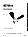
1
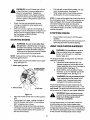
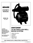
Owner's Manual
CRRFTSMAN
[]
6.5 Horse Power
_]
3" diameter
chipping
m
capacity
CHIPPER-SHREDDER
Model No.
B
247.775870
CAUTION: Before using this product,
read this manual and follow all Safety
Rules and Operating Instructions.
i
Sears, Roebuck and Co., Hoffman
Printed in U,S.A.
Estates, IL 60179, U.S.A.
Page
Content
Content
Page
Warranty Information
2
Service & Adjustment
14
Safe Operation Practices
3
Off-Season Storage
16
Assembly
5
Trouble-Shooting
17
Operation
8
Repair Parts
18
Maintenance
11
One-Year
Warranty
on Craftsman
Chipper-Shredder
For one year from the date of purchase, when this Craftsman chipper-shredder is maintained, lubricated, and
tuned up according to the operating and maintenance instructions in the operator's manual, Sears will repair, free
of charge, any defect in material or workmanship.
This warranty excludes the blades, chipper blades, flails, air cleaners, spark plugs, catcher bags and tires which
are expendable parts and become worn during normal use.
If this chipper-shredder is used for commercial or rental purposes, this warranty applies for only 30 days from the
date of purchase.
WARRANTY SERVICE IS AVAILABLE BY CONTACTING THE NEAREST SEARS SERVICE CENTER IN THE
UNITED STATES. THIS WARRANTY APPLIES ONLY WHILE THIS PRODUCT IS IN USE IN THE UNITED
STATES.
This warranty gives you specific legal rights, and you may also have other rights which vary from state to state.
Sears, Roebuck and Co., D/817WA, Hoffman Estates, II 60179
These accessories were
available when the chippershredder was purchased.
They are also available at
most Sears retailoutlets and
service centers. Most Sears
stores can order repair parts
for you when you provide the
model number of your
chipper-shredder.
PRODUCT
HORSEPOWER:
CRANKCASE
CAPACITY:
Spark
Plug
Air
Filter
Engine
Oil
SPECIFICATION
Gas
Can
Stabilizer
Tow Hitch Kit
Model Number ............. 247.775870 ...........
6.5 H.P.
Serial Number ...........................................................
21oz. SAE 30 ENGINE OIL
Date of Purchase ......................................................
FUEL TANK CAPACITY:
SPARK PLUG:
SPARK PLUG GAP:
3 QUARTS (UNLEADED)
Record both serial number and date of purchase and
keep in a safe place for future reference.
Champion (N4C)
.030
2
This symbol points out important safety instructions which, if not followed, could endanger the personal safety and/or property of yourself and others. Read and follow all instructions in this manual before
attempting to operate your chipper shredder. Failure to comply with these instructions may result in personal injury. When you see this symbol--heed
its warning.
I
Your chipper-shredder
,_
was built to be operated according
to the rules for safe operation
in
DANGER" this manual. As with any type of power equipment, carelessness or error on the part of the oper-
_"
" ator can result in serious injury. If you violate any of these rules, you may cause serious
injury to yourself
,_
GENERAL
or others.
WARNING:
The Engine
Exhaust
from this
known
to
the State of California
to cause
cancer,
birthproduct
defectscontains
or other chemicals
reproductive
harm.
OPERATION
running. Keep clear of the discharge opening at all
times. If it becomes necessary to push material into
the chipper chute or shredder hopper, use a small
diameter stick, NOT YOUR HANDS,
If it is necessary for any reason to unclog the feed
intake or discharge openings or to inspect or repair any
part of the machine where a moving part can come in
contact with your body or clothing, stop the machine,
allow it to cool, disconnect the spark plug wire from the
spark plug and move it away from the spark plug
before attempting to unclog, inspect or repair.
Do not operate unit while under the influence of alcohol
or drugs.
The machine should only be operated on a level
surface. Never operate your unit on a slippery, wet,
muddy or icy surface. Keep your work area clean and
clear of branches or obstacles which could cause you
to stumble and fall Do not overreach. Maintaining
proper footing and balance is essential to preventing
accidents.
Do not allow an accumulation of processed material to
build-up in the discharge area as this will prevent
proper discharge and can result in kick-back from the
chipper chute.
Keep your face and body back from chipper chute to
avoid accidental bounce back of any material.
Do not transport machine while engine is running.
If the cutting mechanism strikes a foreign object or if
your machine should start making an unusual noise or
vibration, immediately stop the engine and allow the
machine to come to a complete stop. Disconnect the
spark plug wire and move it away from the spark plug.
Take the following steps.
a. inspect fordamage.
b. Repair or replace any damaged parts.
c. Check for any loose parts and tighten to assure
continued safe operation.
Never attempt to attach or remove catcher bag when
engine is running. Shut the engine off and wait for the
impeller to come to a complete stop. The impeller
continues to rotate for a few seconds after the engine is
shut off. Never place any part of the body in the
impeller area until you are sure the impeller has
stopped rotating.
Muffler and engine become hot and can cause a burn.
Do not touch.
Read this owner's guide carefully in its entirety before
attempting to assemble this machine. Read,
understand, and follow all instructions on the machine
and in the manual(s) before operation. Be completely
familiar with the controls and the proper use of the
machine before operating it. Keep this manual in a
safe place for future and regular reference and for
ordering replacement parts.
Your chipper-shredder is a powerful tool, not a
plaything. Therefore, exercise extreme caution at all
times. Your unit has been designed to perform two
jobs; to chip and shred vegetation found in a normal
yard. Do not use it for any other purpose.
Never allow children under age 16 to operate the unit.
Children 16 years and older should only operate the
unit under close parental supervision. Only
responsible individuals who are familiar with these
rules of safe operation should be allowed to use your
unit.
Keep ths area of operation clear of all persons,
particulady small children and pets. Stop the engine
when they are in the vicinity of the unit. Keep work
area clean and clear of branches or obstacles which
could cause you to stumble or fall.
When feeding material into this equipment, be
extremely careful that pieces of metal, rocks, bottles,
cans or other foreign objects are not included.
Personal injury or damage to the machine could result.
Always wear safety glasses or safety goggles, during
operation and while performing an adjustment or
repair, to protect eyes from foreign objects that may be
thrown from the machine.
Wear sturdy, rough-soled work shoes and close fitting
slacks and shirt. Shirt and slacks that cover the arms
and legs and steel-toed shoes are recommended. Do
not wear loose fitting clothes or jewelry and secure hair
so it is above shoulder length. They can be caught in
moving parts. Never operate a unit in bare feet,
sandals or sneakers. Wear gloves when feeding
material in the chipper chute or shredder hopper.
Never place your hands, feet, or any part of your body
into the shredder hopper, chipper chute, discharge
opening, or near any moving part while the engine is
3
Do not ailow leaves or other debris to build-up on
engine's muffler. The debris could ignite and cause a
fire.
Do not attempt to shred or chip material larger than
specified in this manual. Personal injury or damage
to the machine could result.
Do not operate engine if air cleaner or cover over
carburetor air-intake is removed, except for
adjustment, Removal of such parts could create a fire
hazard.
c.
Extinguish all cigarettes, cigars, pipes and other
sources of ignition.
d. Never refuel unit indoors because flammable
vapors will accumulate in the area.
e. Never store the machine or fuel container inside
where there is an open flame or spark such as a
gas hot water heater, space heater, clothes
dryer or furnace.
Never run your machine in an enclosed area as the
exhaust from the engine contains carbon monoxide,
which is an odorless, tasteless and deadly poisonous
gas.
To reduce fire hazard, keep engine and muffler free of
leaves, grass, and other debris build-up. Clean up
fuel and oil spillage. Allow unit to cool at least 5
minutes before storing.
Before cleaning, repairing, or inspecting, make certain
the impeller and all moving parts have stopped.
Disconnect the spark plug wire and keep wire away
from spark plug to prevent accidental starting. Do not
use flammable solutions to clean air filter.
Only use accessories approved for this machine by
the manufacturer. Read, understand, and follow all
instructions provided with the approved accessory.
If situations occur which are not covered by this
manual, use care and good judgment. Contact your
dealer for assistance.
Keep discharge discharge chute, chipper chute door,
and ell other guards end safety devices in place and
operating properly.
Only operate unit in good daylight. Do not operate
unit at night or in dark areas where your vision may be
impaired.
Check the blade and engine mounting screws at
frequent intervals for proper tightness. Also visually
inspect blades for wear and/or damage (e.g., bent,
cracked). Replace with blades which meet original
equipment specifications.
Keep all nuts, bolts, and screws tight to be sure the
equipment is in safe working condition.
Never tamper with safety devices. Check their proper
operation regularly.
After stdking e foreign object, immediately stop the
engine, disconnect the spark plug wire from the spark
plug, end thoroughly inspect the unit for any damage.
Repair damage before starting and operating unit.
Do not alter or tamper with the engine's governor
setting. The governor controls the maximum safe
operating speed of the engine. Over-speeding the
engine is dangerous and will cause damage to the
engine and to other moving parts of the machine.
CHILDREN
Tragic accidents can occur if the operator is not alert to the
presence of small children. Children are often attracted to
the chipper-shredder and the chipping and shredding
activity. Never assume that children will remain where you
last saw them.
Keep children out of the work area and under the
watchful eye of a responsible adult other than the
operator.
Be alert and turn the unit off if a child enters the area.
•
Never allow children under the age of 16 to operate
the chipper-shredder.
SERVICE
Use extreme care in handling gasoline end other
fuels. They are extremely flammable and the vapors
are explosive.
a. Store fuel and oil in approved containers, away
from heat and open flame, and out of the reach
of children. Check and add fuel before starting
the engine. Never remove gas cap or add fuel
while the engine is running. Allow engine to
cool at least two minutes before refueling.
b. Replace gasoline cap securely and wipe off any
spilled gasoline before starting the engine as it
may cause a fire or explosion.
YOUR RESPONSIBILITY
Restrict the use of this power machine to
persons who read, understand and follow the
warnings and instructions in this manual and on
the machine.
SAVE THESE INSTRUCTIONS
FOR FUTURE REFERENCE.
This unit is equipped with an internal combustion engine and should not be used on or near any unimproved forestcovered, brush-covered or grass-covered land unless the engine's exhaust system is equipped with a spark arrester
meeting applicable local or state laws (if any). If a spark arrester is used, it should be maintained in effective working
order by the operator.
In the State of California the above is required by law (Section 4442 of the California Public Resources Code). Other
states may have similar laws. Federal laws apply on federal lands. A spark arrester for the muffler is available
through your nearest Sears Authorized Service Center (See the REPAIR PARTS section of this manual.)
4
Carton
REMOVE CHIPPER-SHREDDER
FROM CARTON
Contents
•
•
•
•
•
Cut the corners of the carton.
Remove all packing inserts.
Remove all loose parts including owner's
manual. See figure 1.
Roll chipper-shredder out of the carton.
Make certain all parts and literature have been
removed before the carton is discarded.
LOOSE PARTS
Hopper
Discharge
(Refer to figure 1.)
a. Hopper Assembly
b. Discharge Chute
c. Catcher Bag
d. Bottle of Oil
e. Safety Glasses (not shown in figure 1)
f. Owner's Manual (not shown in figure 1)
g. Chipper Chute
Chute
Catcher Bag
TOOLS REQUIRED
1.
2.
3.
4.
1/2" or Adjustable Wrenches
7/16" or Adjustable Wrenches
9/16" or Adjustable Wrenches
Funnel
DISCONNECTING
Disconnect the spark plug wire and move it
away from the spark plug before assembling the
chipper-shredder. See figure 2.
Chipper Chute
__Bottle
SPARK PLUG
of Oii
• You will find the hopper in the top insert inside the carton.
Spark
Figure 1
Wire
IMPORTANT: This unit is shipped without gasoline
or oil in the engine. After assembly, see OPERATION
section of this manual for proper fuel and engine oil
fill-up.
NOTE: To determine right and left hand sides of your
chipper-shredder, stand behind the unit with the
engine farthest away from you.
Your chipper-shredder has been completely assembled
at the factory, except for the hopper assembly,
discharge chute and the catcher bag.
These parts are shipped loose in the carton. A pair of
safety glasses and a bottle of oil are also included in
the carton.
Figure 2
5
ATTACHING
•
DISCHARGE
CHUTE
Insert the hex bolt (that you earlier removed)
from the left through the hole on the hopper and
the inlet guide. Insert the hex nut onto the bolt
from the other side. See figure 4 inset.
Remove the wing knobs from each side of the
discharge opening on the chipper-shredder. See
figure 3.
Using two 7/16" wrenches, remove hex lock nut,
two spacers, and the hex bolt from top of the
housing assembly. For easy assembly, do not
remove the second spacer from the hex bolt.
Place the discharge chute in position on the
discharge opening. Insert hex bolt and spacer
through hinge on discharge chute and housing
(spacer fits inside of hinge). See figure 3 inset.
•
•
Inlet G_
Hopper Pivot Door
Nu1
Hex Nut
--
Hex Bolt
Sto:
Hinge
Wing
Knob
Inlet Guide
Hopper
Figure 4
Discharge
Chute
Tighten the bolt to remove all sideplay ( after
tightening the bolt, the hopper will pivot up and
down). This will secure the hopper assembly to
the inlet guide.
To raise the hopper, hold the hopper by the
hand-hold and lift it up till it clicks into
position.See figure 5.
tg Knob
Figure 3
Place second spacer over hex bolt inside the
other half of the hinge. Secure with hex lock nut.
Tighten securely.
Secure both sides of discharge chute to housing
using wing knobs that you earlier removed.
Tighten wing knobs.
ATTACHING
•
•
•
•
•
HOPPER
1. Lift
ASSEMBLY
Remove the 8-3/8" long hex bolt and the hex nut
from the bottom of the inlet guide opening. See
figure 4 inset.
Place the hopper assembly on the ground and
hold it in the position shown in step 1 in figure 4.
Holding the hopper, push hopper pivot door
down inside the hopper. See figure 4.
Slide the hopper assembly towards the chippershredder housing so that the upper guide on the
hopper assembly slides under the stop washer
on each side of the inlet guide. See figure 4.
Align the two holes (one on each side) of the
lower hopper with the two holes (one on each
side) of the inlet guide.
2. Pull release bar
Figure 5
•
To Iowerthe hopper, hold the hopper by the
hand-hold and pull the release bar. The hopper
should drop down. See figure 5.
The flap control rod is already attached to the hopper
at the top. The other end of the rod has to be attached
6
to the stop washer on the inlet guide. See figure 6.
,_
device
to hold
the flap
flap control
in placerod
inside
the
WARNING:
This
is a safety
hopper while shredding branches. Do not
operate the chipper-shredder without
properly attaching this flap control rod.
•
•
•
Hopper
•
and hex nuts that you earlier removed• Do not
tighten the nuts at this time. Make sure to place
the cupped side of the washer against the
chipper chute.
Align the holes towards the front opening of the
chute with the holes on the brace. See figure 7.
Insert one each of the hex bolts, lock nuts, and
flat washers (that you earlier removed) through
each hole in the chute and the brace. Tighten
these bolts to secure brace to the chute.
Tighten bolts securingthe brace to the lower
frame. These boltshad been removed earlier.
Tighten the three nuts on the weld studs.
Chipper
Chute
Cw::::Weld Stud
Weld Stud
Attach flap
control rod
here
f
Washer
Flap Control
Rod
* Do not removethese hardwarefromthe inletguide
assembly while attachingthe flap controlrod.
Chute
Brace
Figure
7
Figure 6
•
•
•
•
Raise the hopper till it clicks into position.
Unscrew the shoulder bolt from the stop washer
on the inlet guide. See figure 6.
Align the loose end of the flap control rod with
the stop washer on the inlet guide.
Slide the shoulder bolt through the opening in
the flap control rod. Secure tightly. See figure 6.
ATTACHING
•
•
•
•
•
THE CHIPPER
CHUTE
Your unit is shipped with one end of the brace
already secured to the lower frame. Loosen the
bolts securing the brace to the frame.
Remove the three cupped washers and hex
nuts from the weld studs beside the opening on
the left side of the housing. See figure 7.
Remove the two sets of hex bolt, lock nut, and
flat washer from the two holes on the upper end
of the brace as shown in figure 7.
Place the chipper chute over the weld studs so
the slot on the chute is towards the bottom. Align
the three holes at the bottom of the chute with
the three weld studs.
Secure with the three pairs of cupped washers
ATTACHING
THE CATCHER
BAG
Your chipper-shredder is equipped with a catcher bag
to catch the shredded material.
•
To attach the bag, place the bag opening over
the discharge chute so it completely covers the
discharge chute and goes over the chute
flanges.
•
Depress the plunger on the draw-string, and pull
on the drew-string until the bag is tight around
the chute opening. Release plunger to lock it into
position. See figure 8.
Drawstring
Bag
Figure 8
I
Read this owner's manual and safety rules before operating your chipper-shredder. Compare the illustration in I
figure9withy_urchipper_shreddert_fami_iarizey_urselfwiththe__cati_n_fVari_usc_ntr__sandadjustments_
_1
Save this manual for future reference.
I
The operation of any chipper-shredder can result in foreign objects being thrown into the
eyes, which can result in severe eye damage. Always wear safety glasses provided w th
the chipper-shredder or eye shields before chipping or shredding, or while performing any
adjustments or repairs.
Discharge Chute
Hopper
f
Chipper
Assembly
Chute
Release
Bar
Primer
Button
Throttle
Control
Starter
Handle
Figure 9
OPERATING
CONTROLS
Lower the hopper to collect raked materiat for
shredding.
Release Bar
Chipper Chute
Used to release the hopper when raising or lowering.
Allows bulky vegetation like stalks or heavy branches
upto 3" diameter to be fed into the impeller for
chipping and shredding.
Starter Handle
Used to manually start the engine.
Primer Button
Throttle Control
Fills carburetor with gasoline to aid in starting a cold
engine.
Regulates speed of the engine.
Catcher Bag
STOPPING
Used to collect the shredded material. (not shown)
Hopper Assembly
ENGINE
Move throttle control lever to STOP position.
Disconnect spark plug wire and move away from
spark plug to prevent accidental starting.
Allows leaves and small branches upto 0.5 "diameter
to be fed into the impeller for chipping and shredding.
MEETS ANSI SAFETY STANDARDS
Sears chipper-shredders conform to the safety standard B 71.6 -1990 of the American National Standards Institute.
8
&
,_
GAS AND OIL FILL-UP
Oil (Packed with unit)
•
Tilt chipper-shredder toward the left (from behind
the hopper). See figure 11. Check oil level. Put the
unit back on the ground carefully.
WARNING:
Before using your chippershredder, refer to the safety rules on
pages 3 and 4 of this manual again.
Always be careful.
Only use high quality detergent oil rated with
API service classification SF, SG or SH. Select
the oil's viscosity grade according to your
expected operating temperature. Follow the
chart below.
Co der _
_.==_.o
5W30
hand-hold.
WARNING:
Do not tilt unit holding the
Add oil if necessary. Replace dipstick and
tighten.
32°F _
Warmer
L
I
SAE 30
NOTE: Although multi-viscosity oils (5W30, 10W30,
etc.) improve starting in cold weather, these
multiviseosity oils will result in increased oil
Hold unit this
to tilt
consumption when used above 32°[::. Check the oil
level more frequently to avoid possible engine
damage from running low on oil.
Fill engine with oil as follows.
•
Remove dipstick. See figure 10.
1. Remove dipstick
end fill oll
2. Remove cap
and fill gas
F
Figure 10
With chipper-shredder on level ground, use a
funnel to fill engine with oil to FULL mark on
dipstick. Capacity is approximately 20 ounces.
Be careful not to overfill.
Figure 11
NOTE: Do not overfill. Oil bottle packed with unit
contains 20 oz. of oil.
Gasoline
Warning: Experience indicates that alcohol blended
fuels (called gasohol or using ethanol or methanol)
can attract moisture which leads to separation and
formation of acids during storage. Acidic gas can
damage the fuel system of an engine while in storage.
To avoid engine problems, the fuel system should be
emptied before storage for 30 days or longer. Drain
the gas tank, start the engine and let it run until the
fuel lines and carburetor are empty. Use fresh fuel
next season. See STORAGE instructions for
additional information. Never use engine or
carburetor cleaner products in the fuel tank or
permanent damage may occur.
Fill gas tank with gas as follows.
•
Remove fuel cap. See figure 10.
•
Make sure the container (from which you will
pour the gasoline) is clean and free from rust or
foreign particles. Never use gasoline that may
be stale from long periods of storage in the
container.
•
Fill fuel tank with fresh, lead-free gasoline. DO
NOT use Ethyl or high octane gasoline.Replace
fuel cap.
WARNING: Do not fill closer than
1/2 inch
of top of fuel tank to prevent spills and to
allow for fuel expansion. If gasoline is
accidently spilled, move chipper-shredder
away from area of spill. Avoid creating any
source of ignition until gasoline vapors have
disappeared.
•
•
NOTE: A noise will be heard when finding the start of
the compression cycle. This noise is caused by the
flails and fingers which are part of the shredding
mechanism falling into place, and should be
expected. In addition, the flails and fingers will be
noisy after the engine is started, until the impeller
reaches furlspeed.
Check the fuel level periodically to avoid
running out of gasoline while operating the
chipper-shredder.
If the unit runs out of gas as it is shredding or
chipping, it may be necessary to unclog the unit
before it can be restarted. Refer to Removing
the Flail Screen in SERVICE AND
ADJUSTMENT section.
STARTING
STOPPING
•
ENGINE
WARNING:
Pull rope with a rapid full arm stroke. Let rope
return to starter slowly. See figure 12.
When engine starts, move throttle control to
IDLE position for a few minutes warm-up.
•
Be sure no one other than
ENGINE
Move throttle control lever to STOP position
(DOWN).
Disconnect spark plug wire and move away from
spark plug to prevent accidental starting.
USING YOUR CHIPPER-SHREDDER
the operator is standing near the chippershredder while starting or operating. Do not
operate this chipper-shradder unless the
discharge chute has been properly installed
and is secured with the hand knobs.
WARNING:
Do not attempt to shred or
chip any material other than vegetation
found in a normal yard (i.e., branches,
leaves, twigs, etc.).
NOTE: To prevent the unit from sliding, place your
foot firmly against the tire.
The chipper-shredder is designed for two different
methods of operation.
a. Leaves and small branches up to 1/2"
diameter (maximum) can be fed into the
hopper assembly when it is in the raised or
lowered position. See figure 13.
b. Bulky material, such as stalks or heavy
branches, up to 3" in diameter can be fed
into the chipper chute. See figure 13.
Attach spark plug wire and rubber boot to spark
plug. See figure 12.
1. Attach spark plug wire
2. Place Throttle
in Fast Position
WARNING:
Do not put material larger
than is specified into the hopper or the
chipper chute. Personal injury and/or
damage to the machine could result.
3. Prime 3 times
•
•
•
If it becomes necessary to push material into the
chipper-shredder, use a small diameter stick-- not
your hands, The stick should be small enough that it
will be ground up if it gets into the impeller assembly.
4. Pull rope
WARNING:
Never remove discharge
chute till the unit has completely stopped.
Never turn off the engine until all
chipping is completed,
Figure 12
Place the throttle control lever in FAST position
(UP).
Push primer 2 or 3 times, waiting a couple of
seconds between each push. In cold weather
For best performance, it is important to keep the
shredding blade and the chipper blades sharp.
If the composition of the material being discharged
changes (becomes stringy, etc.) or if the rate at which
the material is discharged slows down considerably, it
is likely that the shredding blade and/or chipper
(50°F or below) prime 5 times.
Grasp starter handle and pull rope out slowly
until engine reaches start of compression cycle
(rope will pull slightly harder at this point). Let
the rope rewind slowly.
10
TO LOWER THE HOPPER
ASSEMBLY
blades are dull and need to be sharpened or
replaced. To sharpen or replace the blades, refer to
Service and Adjustments section.
IMPORTANT: There is a flail screen located inside
the housing in the discharge area. If the flail screen
becomes clogged, remove and clean as instructed in
the Service and Adjustments section on page 14.
•
To lower the hopper assembly, use one hand to
grasp the hand-hold at the top of the hopper
assembly and lift slightly. Refer to figure 5.
Pull up on the release bar, and lower the hopper
assembly to the ground. Release the bar. Refer
to figure 5.
•
WARNING:
The chipper-shredder discharges materials with considerable velocity. Keep away from
the area around the discharge chute. Always stop the engine and disconnect spark plug wire when
removing or attaching the bag, changing containers, or removing the shredded material. Wear safety
glasses and gloves whenever using your chipper-shredder.
Shred material upto 112 inch in diameter
\
Figure 13
GENERAL
•
•
•
•
•
RECOMMENDATIONS
Always observe safety rules when performing
any maintenance.
The warranty on this chipper shredder does not
cover items that have been subjected to operator
abuse or negligence. To receive full value from
the warranty, operator must maintain the
chipper-shredder as instructed in this manual.
Some adjustments will be needed periodically for
proper maintenance of your chipper shredder.
These adjustments are covered in the following
section of this manual.
All adjustments mentioned here should be
checked at least once each season.
Follow the maintenance
Periodically check all fasteners and make sure
these are tight.
CLEANING
•
•
Clean the chipper-shredder by running water
from a hose through the hopper assembly and
chipper chute with the engine running. Allow the
chipper-shredder to dry thoroughly.
Wash the bag periodically with water. Allow to
dry thoroughly in the shade. Do not use heat.
WARNING: Always stop the engine and
disconnect the spark plug wire before
performing any maintenance or adjustments.
Never remove discharge chute tillthe engine
has completely stopped.
schedule given below.
11
ENGINE MAINTENANCE
Air Cleaner
The air cleaner prevents damaging dirt, dust, etc.,
from entering the carburetor and being forced into the
engine and is important to engine life and
performance. The air cleaner consists of a precleaner or foam filter, and a paper filter. Never run
the engine without air cleaner completely assembled.
Engine Oil
•
•
•
•
Only use high quality detergent oil rated with
API service classification SF, SG or SH. Select
the oil's viscosity grade according to your
expected operating temperature. Refer to page
9 of this manual for viscosity chart.
The four-cycle engine of your chipper-shredder
will normally consume some oil. Therefore,
check engine oil level regularly approximately
every five hours of operation and before each
usage.
Stop engine and wait several minutes before
checking oil level. With engine on level ground,
the oil must be to FULL mark on dipstick.
Change engine oil after the first five hours of
operation, and every twenty-five hours
thereafter.
--
_Cover
Base
/
To Drain Oil
Paper Filter
/
Pre-Cleaner
Drain oil while engine is warm. Follow the instructions
given below.
•
Remove oil drain plug. Catch oil in a suitable
container.
•
•
When engine is drained of all oil, replace drain
plug securely.
Refill with fresh oil. Refer to GAS AND OIL FILLUP section. Replace dipstick.
CUSTOMER
Figure 14
RESPONSIBILITIES
MAINTENANCE
_#
@'_ _
,@
I--
Oil pivot points
0
Clean shredder
Check
LU
z
engine
oil
Change engine oil
Wing Nut
_
_
_
Service air cleaner
z
LU
Clean engine
_
Reset spark plug
_
Clean muffler
12
,,_
_
SERVICE
To Service Air Cleaner:
1.
2.
3.
•
Service pre-cleaner after every 25 hours of use,
or at least once a season.
Service filter every 100 hours of use, or at least
once a season.
Service pre-cleaner and filter more often under
dusty conditions.
Remove wing nut and cover. For location, see
figure 14 inset.
Slide pre-cleaner off filter. Clean the inside of
base and cover thoroughly. See figure 14.
Clean pre-cleaner as follows:
c. Wash in water and detergent solution, and
squeeze (do nottwist) until all dirtisremoved.
d. Rinse thoroughly in clear water.
e. Wrap in a clean clothand squeeze (do not
twist) untilcompletely dry, or allow to air dry.
f. Saturate with engine oil and squeeze (don't
twist) to distributeoil and remove excess oil.
NOTE: If the pre-cleaner is torn or damaged in any
way, replace it,
•
•
•
•
If necessary, replace paper filter ---do not
attempt to clean. Install new filter on base.
Slide pre-cleaner over filter.
Install cover and wing nut.
Tighten wing nut securely.
_1_
Spark Plug
Clean the spark plug and reset the gap to .030"
at least once a season or every 50 hours of
operation. See figure 16. Spark plug
replacement is recommended at the start of
each season. Refer to engine parts list for
correct spark plug type.
.030" Feeler
_
•
Clean engine periodically. Remove dirt and
debris with a cloth or brush.
Frequently remove grass clippings, dirt and
debris from cooling fins, air intake screen and
levers and linkage. This will help ensure
adequate cooling and correct engine speed.
See figure 15.
Guage
g
Figure 16
NOTE: Do not sandblast spark plug. Spark plug
should be cleaned by scraping or wire brushing and
washing with a commercial solvent.
Muffler
Inspect periodically, and replace if necessary. If
your engine is equipped with a spark arrester
screen assembly, remove every 50 hours for
cleaning and inspection. Replace if damaged.
Clean Engine
•
nearby areas Temperature
WARNING:
may exceed 150
of muffler
° F(65°C).
and
Avoid these areas.
WARNING:
Do not operate the chippershredder without a muffler, or tamper with
the exhaust system. Damaged mufflers or
spark arresters could create a fire hazard.
LUBRICATION
Lubricate the pivot points on the release bar, hopper
assembly, and discharge chute once a season using
a light oil. Refer to the lubrication chart in figure 17.
Clean cooling
Figure 15
Yearly or every 25 hours, whichever occurs first,
remove the blower housing and clean the areas
shown in figure 15 to avoid overspeeding,
overheating and engine damage. Clean more
often if necessary.
NOTE: Cleaning with a forceful spray of water is not
recommended as water could contaminate the fuel
system.
Figure 17
13
CLEANING
THE FLAIL SCREEN
Remove the flail screen as instructed in previous
section.
Using a 1/2" wrench, remove the chipper chute
by removing three hex nuts and washers. See
figure 18. (Only two hex nut positions shown in
figure.)
If the discharge area becomes clogged, remove the
flail screen and clean area as follows.
•
•
•
Stop engine, make certain the chipper-shredder
has come to a complete stop and disconnect
spark plug wire from the spark plug.
Remove the two hand knobs on each side of the
discharge chute. Lift the discharge chute up,
and keep it out of the way.
Remove two hairpin clips from the clevis pins
which extend through the housing. Remove the
clevis pins. See figure 18.
NOTE: When reassembling, the cupped washer goes
on the slot toward the bottom of the chipper chute with
the cupped side against the chute.
Rotate the impeller assembly by hand until you
locate one of the two chipper blades in the
chipper chute opening. Remove the blade, using
a 3/16" allen wrench on the outside of the blade
Discharge Chute
and 1/2" wrench on the impeller assembly
(inside the housing). See figure 19.
Chipper Chute_'
Hairpin
Clips,
Clevis
Pins
Blade
Slot
Discharge Chute
Screen
Hexl=ut,
Washer
Knobs
Figure 18
•
Pul!the flail screen from inside the housing. See
figure 18. Clean the screen by scraping or washing
with water.
•
Reinstall the screen. Put the discharge chute
back to its original position and tighten the hand
knobs.
Figure 19
Remove the other blade in the same manner.
Replace or sharpen blades.
If sharpening, make certain to remove an equal
amount from each blade.
Reassemble in reverse order. Make certain
blades are reassembled with the sharp edge
facing the direction shown in figure 19 (sharp
edge is assembled toward the slotted opening at
the bottom).
Torque bolts and nuts to 250-350 inch-pounds.
NOTE: Be certain to reassemble the flail screen with
the curved side down.
SHARPENING
BLADES
OR REPLACING
THE
Chipper Blades
•
Disconnect spark plug wire and move it away
from spark plug.
14
ShreddingBlade
Theshreddingblade
angle of grind as a guide. It is extremely
important that each cutting edge receives an
equal amount of grinding to prevent an
unbalanced blade.
An unbalanced blade willcause excessive
vibration when rotatingat high speeds and may
cause damage to the unit. The blade can be tested
for balance by balancing it on a roundshaft
screwdriver or nail. Remove metal from the heavy
side until it is balanced evenly. See figure 21.
When reassembling the blade, tighten center
bolt to between 550 and 650 inch-pounds and
the two outer bolts to between 250 and 350 inch-
may be removed for sharpening
or replacement as follows.
•
Disconnect spark plug wire and move it away
from spark plug.
•
Lower the hopper assembly. Block up the
housing. See figure 20.
Weld Bolt
Allen Screws
pounds, or lacking torque wrench, tighten
securely.
I. Insert screw driver through hole
Pipe
d./
2. Blade should be parallel to ground
Scre_
Driver'_
Blade
_1 o' ol--
Blade
Ground
Figure 20
•
•
Remove the six hex lock nuts and lock washers
from the housing weld bolts using a 1/2" wrench.
Separate the chipper-shredder into two halves.
Remove the back-up plate.
Figure 21
ADJUSTING
NOTE: When reassembling, make certain the
embossed tab faces inward towards the impeller, and
opening on the back-up plate is toward the bottom of
the unit.
•
•
•
•
_hL
•
CARBURETOR
WARNING: If any adjustments are made to
the engine while the engine is running (e.g.
carburetor),keep clear of all moving parts.
Be careful of heated surfaces and muffler.
Remove the two hand knobs and cupped
washers which secure the discharge chute.
Raise the discharge chute.
Insert a 1/2" or 3/4" diameter pipe through the
flail screen into the impeller to keep it from
turning, or remove the flail screen and insert a
piece of wood (2 x 4) into the chute opening.
Remove the two outside screws on the blade,
using a 3/16" allen wrench and a 1/2" wrench.
Remove the blade by removing the center bolt,
lock washer and flat washer.
The carburetor has been pre-set at the factory and
should not require adjustment. However, if your
engine does not operate properly due to suspected
carburetor problems, take your chipper-shredder to
your nearest SEARS service center.
ENGINE SPEED
The engine speed on your chipper-shredder has been
set at the factory. Do not attempt to increase engine
speed or it may result in personal injury. If you believe
the engine is running too fast or too slow, take your
chipper-shredder to the nearest SEARS service
center for repair and adjustment.
the
blade to avoid
theremoving
weld bolts
WARNING:
Use contacting
caution when
on the housing.
When sharpening the blade, follow the original
15
A
WARNING:
Never store machine with fuel
in the fuel tank inside of building where
fumes may reach an open flame or spark,
or where ignition sources are present such
as hot water and space heaters, furnaces,
clothes dryers, stoves, electric motors, etc.
NOTE: Fuel stabilizer is an acceptable a/temative in
minimizing the formation of fuel gum deposits during
storage.
•
•
A yearly check-up by your local Sears service center
is a good way to make certain your chipper-shredder
will provide maximum performance for the next
season.
CHIPPER-SHREDDER
Clean the chipper-shredder thoroughly.
Wipe unit with an oiled rag to prevent rust (use a
light oil or silicone).
ENGINE
•
Drain the fuel tank.
•
Start the engine and let it run until the fuel lines
and carburetor are empty.
Never use engine or carburetor cleaner products
in the fuel tank or permanent damage may
•
Run engine at least 10 minutes after adding
stabilizer to allow the stabilizer to reach the
carburetor.
•
Do not drain the gas tank and carburetor if using
fuel stabilizer. Drain all the oil from the crankcase
(this should be done after the engine has been
operated and is stillwarm) and refill the
crankcase with fresh oil.
•
If you have drained the fuel tank, protect the
inside of the engine as follows.
Remove spark plug, pour approximately 1/2
ounce (approximately one tablespoon) of engine
oil into cylinder and crank slowly to distribute oil.
Replace spark plug.
•
OTHER
Do not store gasoline from one season to
another.
Replace your gasoline can if your can starts to
rust. Rust and/or dirt in your gasoline will cause
problems. Store unit in a clean, dry area. Do not
store next to corrosive materials, such as
fertilizer.
NOTE: If storing in an unventilated or metal storage
shed, be certain to rustproof the equipment by coating
with a light oil or silicone.
Occur,
•
•
•
IMPORTANT: It is important to prevent gum deposits
from forming in essential fuel system parts such as
carburetor, fuel filter, fuel hose, or tank during
storage. Also, experience indicates that alcohol
blended fuels (called gasohol or using ethanol or
methanol) can attract moisture which leads to
separation and formation of acids during storage.
Acidic gas can damage the fuel system of an engine
while in storage.
Add stabilizer to gasoline in fuel tank or storage
container.
Always follow the mix ratio found on stabilizer
container.
Use fresh fuel next season.
16
PROBLEM
Engine fails to start
POSSIBLE
CAUSE
1. Fuel tank empty, or stale fuel
2. Spark plug wire disconnected
3. Faulty spark plug
4. Throttle control not in correct
position
Loss of power; operation erratic
1. Spark plug wire loose
2. Unit running on Choke
3. Blocked fuel line or stale fuel
4. Water or dirt in fuel system
5. Carburetor out of adjustment
6. Dirty air cleaner
Engine overheats
1. Carburetor not adjusted properly
2. Engine oil level low
CORRECTIVE
1.
2.
3.
4.
ACTION
Fill tank with clean, fresh fuel
Connect wire to spark plug.
Clean, adjust gap or replace.
Move throttle control to FAST
position
1. Connect and tighten spark plug
wire.
2. Move choke lever to OFF
position.
3. Clean fuel line; fill tank with
clean, fresh gasoline.
4. Disconnect fuel line at carburetor
to drain fuel tank. Refill with fresh
fuel.
5. Contact your SEARS service
center.
6. Service air cleaner.
1. Contact your SEARS service
center.
2. Fill crankcase with proper oil.
Too much vibration
1. Loose parts or damaged
impeller
1. Stop engine immediately and
disconnect spark plug wire.
Tighten all bolts and nuts. Make
all necessary repairs. If vibration
continues, have unit serviced by
a SEARS service center.
Unit does not discharge
1. Discharge chute clogged
1. Stop engine immediately and
disconnect spark plug wire.
clean flail screen and inside of
blower housing.
2. Stop engine immediately and
disconnect spark plug wire.
Remove lodged object.
2. Foreign object lodged in
impeller
Rate of discharge slows
considerably or composition of
discharged material changes
1. Shredding blade and/or chipping
blade dull
For repairs beyond the minor
adjustments listed above, please
contact your nearest SEARS
service center.
17
1. Sharpen or replace blade(s).
SEARS CRAFTSMAN
6.5 H.P. CHIPPER-SHREDDER
MODEL 247.775870
,/62
29
66
\
8
13
17
48
64
42
j
'i
53
42
58
18
SEARS CRAFTSMAN
Key
No
6.5 H.P. CHIPPER-SHREDDER
Pe_ No
770-1231A
Owner's
Manual
Pa_ No
Description
38
710-0157
Hex Bolt 5/16-24 X .75"
Lock Washer 5/16" Id
Stop Washer
39
736-0119
681-0111
Inlet Guide Assembly
40
710-1054
Flat Hd. Screw 5/16-24 X .75"
3
681-0144
Arm Bracket Assembly
41
781-0490
4
710-0542
Hex Flange Bolt: 5/16-18
8.375" (gr.5)
42
719-0329
Chipper Blade
Flail Blade
43
715-0166
Spring Roll Pin
710-0607
Hex Washer Head Self-Tapping Screw: 5/16-18 x 0,5"
44
712-0411
Hex Top Lock Nut 5/16-24
(gr. 5)
710-3256
Button-Head
0.5"
45
735-0249
46
736-0247
Shredder Chute Flap
Flat Washer .406" ID X 1.25"
OD
47
711-0833B
Clevis Pin
48
710-3008
Hex Bolt 5/16-18 X 1.5"
1
2
6
_11480
Key
No
Description
MODEL 247.775870
Screw
x
1/4-20
x
7
712-0429
Lock Nut: 5/16-18
8
712-3027
Hex Flange
9
714-0104
Internal Cotter
10
715-0129
Spiral Pin
49
710-0825
Hex Bolt 1/4-20 X 3.75"
726-0106
Cap Nut
50
711-0835
Clevis Pin
12
726-0135
Speed Cap Nut
51
736-0217
Lock Washer
13
728-0175
Pop Rivet
52
681-0004A
Flail Housing Assembly: Outer
14
732-0546
Torsion Spring
53
681-0117
15
732-0629
54
726-0214
Flail Housing Assembly: Inner
Push Cap 5/8" Dia,
16
735-0127
Hopper Door Spring
Rubber Washer
55
734-1600
Wheel Assembly Comp.
17
735-0651
750-0786
736-0119
Hopper Flap
Lock Washer
56
18
57
738-0814
Spacer
Shredder Axle
19
738-0137A
Shdr. Scr: .340 x .285 x 1/4-20
58
712-3004A
Hex Lock Nut 5/16-18 (Gr.5)
20
738-0946
Shdr. Scr: .56 x ,165 x 5/16-18
59
736-0170
21
747-0531A
Ret. Rod: 5/16"
60
781-0510B
Special Lock Washer
Shredder Frame
22
747-0747
Hopper Door Rod
61
710-0805
Hex Bolt 5/16-18 x 1.5"
23
747-1124
Flap Retaining
Rod
62
761-0633
Chute Flap Strip
24
747-1125
Flap Retaining
Bail
63
728-0175
Pop Rivet
25
781-0492A
Hopper Pivot Door
64
26
781-0633
Chute Flap Strip
27
781-0698
65
781-0735
28
781-0715
Hopper Lock Bracket
Shredder Plate
66
710-0751
Pin Retaining Clip
Hex Bolt 1/4-20 x .625
29
781-0752
Flap
67
736-0173
Flat Washer .28 I.D. x .74 O.D.
30
781-0754-0483
Upper
Hopper
68
742-0571
Shredder Blade
31
781-0755-0483
712-3027
Flanged Lock Nut
32
720-0170
Lower Hopper
Hand Knob
69
70
749-1004
Chipper Chute Support
33
34
750-0793
Chute Hinge Spacer
Internal Cotter Pin
71
710-0106
Hex Screw 1/4-20 x .625 (gr. 21
72
681-0068
35
Discharge
73
712-3010
36
681-0094-0483
781-0457
Screen
74
736-0242
Chipper Chute Assembly
Hex Nut 5/16-18 (gr. 5)
Bell Washer .345" I.D. x .88"
37
681-0030
impeller
Assembly
75
731-1899
Chipper Chute
11
714-0149B
Lock Nut: 1/4-20
Mounting
Shredder
Pin
dia.
Bracket
Chute Assembly
19
Engine: Tecumseh 6.5 hp.
OHH65-71701
|
|
SEARS CRAFTSMAN
CHIPPER-SHREDDER
6,5 H.P. ENGINE MODEL 143.986501
FOR
MODEL 247.775870
161
161A
307
900
I
173
279
305
310 --
\
154
155
159
308
4O
130
135
6
41
120
}--43
130A
126
125
/
119
s
82
16
38
2
5
_207
252
240
182
245
185 /
184
245A
_ •
/
250A
/
251
20
SEARS CRAFTSMAN
6.5 H.P. ENGINE MODEL 143.986501
CHIPPER-SHREDDER
65
FOR
MODEL 247.775870
341
60
342
\
lOO
292
25A
26
£0
110
370A
313
261
261A
I
260
390
287
/
/
327
21
O
SEARS CRAFTSMAN
CHIPPER-SHREDDER
Key No.
1
2
4
5
14
15
16
19
2O
25
25A
26
30
35
37
38
40
41
42
43
45
46
48
49
5O
60
64
65
69
70
72
75
80
81
82
83
86
89
90
92
93
100
101
103
110
Part No.
37120A
26727
31857
30969
651051
37108
37110
37111
32600
36621
36622
30200
36831
651053
29216
37109
40004
40005
36070
36071
40006
40007
20381
32875A
32610A
35616
36611
37040
36623A
651015
30200
36624
36625
27897
30574A
30590A
30591
36057
650488
610961
611205
650815
650816
34443B
610118
651007
36054
6.5 H.P. ENGINE MODEL 143.986501
FOR
MODEL 247.775870
Description
Key No.
Part No.
Description
RPM High 3450 to 3750
RPM Low 2000 to 2300
Cylinder (Incl. 2, 20 & 72)
Dowel Pin
Oil Drain Extension
Extension Cap
Washer
Governor Rod
Governor Lever
119
12O
125
36719
36721
36471
36472
29314C
29315C
650912
650999
34645
37039
31673
36649
650913
35624A
650914
36629
35626
36630A
651008
651012
36675A
650852
650451
26756
36631
36711
36736
610973
36632
650821
36638
650451
36581
28820
27272A
36633
36046
36634
37073
650886
650821
36864
651008
650821
651008
36722
650988
36674
650852
36893
35985B
Cylinder Head Gasket
Cylinder Head
Exhaust Valve (Std.) (Incl. 151)
Exhaust Valve (1/32" O.S.) (IncL 151)
Intake Valve (Std.) (Incl. 151)
Intake Valve (1/32" O.S.) (Incl. 151)
Screw, 5/16-18 x 1-1/2"
Screw, 5/16-18 x 2-41/64"
Spark Plug (N4C)
Valve Spring
Valve Spring Cap
Push Rod Guide
Rocker Arm Stud
Rocker Arm
Nut, 1/4-28
Push Rod
Rocker Arm Cover Gasket
Rocker Arm Cover
Screw, 1/4-20 x 31/64"
Stud
Breather Tube
Nut, 1/4-20
Screw, 1-4-20 x 1"
Carburetor to Intake Pipe Gasket
Intake Pipe
Governor Link
126
Extension Spring
Oil Seal
Air Baffle (Left)
Air Baffle (Right)
Screw, 10-24 x 9/16"
Crankshaft
Screw, 10-32 x 63/64"
Lock Nut, 10-32
Retaining Ring
Piston, Pin, And Ring Set (Std.)
Piston, Pin, And Ring Set (.010" O.S.)
Piston & Pin Ass'¥ (Std.) (Incl. 43)
Piston & Pin Aes'y (.910" O.S.)(Inel. 43)
Ring Set (Std.)
Ring Set (.010" O.S.)
Piston Pin Retaining Ring
Connecting Rod Ass'y. (Incl. 46 & 49)
Connecting Rod Bolt
Valve Lifter
Oil Dipper
Camshaft
Blower Housing Extension
Screw, 1/4-20 x 1-1/8"
Screw, 10-24 x 9/16"
Cylinder Cover Gasket
Cylinder Cover (Incl. 75 thru 83)
Oil Drain Plug
Oil Seal
Governor Shaft
Washer
Governor Gear Ass'y. (Incl. 81)
Governor Spool
Screw, 1/4-20 x 1-1/4"
Flywheel Key
Flywheel
Belleville Washer
Flywheel Nut
Solid State Ignition
Spark Plug Cover
Screw, Torx "1"-15,10-24 x 15/16"
Ground Wire
22
130
130A
135
150
151
153
154
155
157
158
159
160
161
161A
173
178
182
184
185
186
20O
206
2O7
2O9
215
223
224
238
239
240
245
245A
250
251
252
260
261
261A
262
275
277
278
279
280
285
287
290
292
3O0
301
30705
26460
36863
36246
Control Bracket (Incl. 206 & 215)
Terminal
Throttle Link
Screw, 10-32 x 1/2"
Control Knob
Screw, 1/4-20 x 1"
Intake Pipe Gasket
Screw, 10-32 x 1/2"
Air Cleaner Gasket
Air Cleaner Body (Incl. 239)
Air Cleaner Filter
Air Cleaner Filter
Air Cleaner Cover
Wing Nut
Screw, 10-32 x 1/2"
Blower Housing
Screw, 1/4-20 x 31/64"
Screw, 10-32 x 1/2"
Screw, 1/4-20 x 31/64"
Muffler
Screw, 1/4-20 x 2-9/32"
Spacer
Nut & Lock Washer
Heat Shield
Starter Cup
Rivet (Can be purchased locally)
Fuel Line
Fuel Line Clamp
Fuel Tank (Incl. 292 & 301)
Fuel Cap
SEARS CRAFTSMAN
6.5 H.P. ENGINE MODEL 143.986501
CHIPPER-SHREDDER
FOR
MODEL 247.775870
Key
No.
Pad
No.
Descri_ion
Key
No.
Part
No.
Description
305
307
308
310
313
325
327
341
342
35554
35499
37079
36902
34080
29443
35392
36644
651010
Oil FiJlTube
"O"-Ring
Fill Tube Clip
Dipstick
Spacer
Wire Clip
Starter Plug
Fuel Tank Bracket
Screw, 1/4-20 x 7/8"
370A
370B
380
390
400
416
417
900
900
36261
35703
640025B
590736
36720
36085
650760
---
Lubrication Decal
Speed Control Decal
Carburetor (Incl. !84)
Rewind Starter
Gasket Set
Spark Arrester Kit (Incl, 417)(Optional)
Screw, 8-32 x 3/8"
Replacement Engine -- none
Replacement S/B 754299A
Order Form 71-999
Carburetor
Key
No.
"_
_20A
/
48...Q
Part
No.
Description
640025B
Carburetor (Incl. 184 of Engine
Parts List)
Throttle Shift & Lever Assembly
Throttle Return Spring
Dust Seal Washer
Dust Seal (Throttle)
Throttle Shutter
Shutter Screw
1
2
4
5
6
7
16
17
631615
631767
631184
631183
631036
650506
632164
651025
18
20
20A
25
27
28
29
30
31
35
36
37
40
44
47
48
630766
640018
640053
631867
631024
632019
631028
631021
631022
36045A
640019
632547
640015
27110
630748
631027
I
29/
28/__/27
_--
_--
37
37
25/_
4O
23
Fuel Fitting
Throttle Crack Screw/Idle Speed
Screw
Tension Spring
Idle Restrictor Screw
Idle Rsstrictor Screw Cap
Float Bowl
Float Shaft
Float
Float Bowl "O"-Ring
Inlet Needle, Seat & Clip (incL.31)
Spring Clip
Primer Bulb/Retainer Ring
Main Nozzle Tube
"O"-Ring, Main Nozzle Tube
High Speed Bowl Nut
Bowl Nut Washer
Welch Plug, Idle Mixture Well
Welch Plug, Atmospheric Vent
SEARS CRAFTSMAN
6.5 H.P. ENGINE MODEL 143,986501
CHIPPER-SHREDDER
Recoil
FOR
MODEL 247.775870
Starter
O
Key
No.
Part
No.
Description
590736
590599A
590600
590696
590601
590697
590698
590699
590700
590705
590535
590701
Rewind Starter
1
2
3
4
5
6
7
8
11
12
13
Spring Pin (Incl, 4)
Washer
Retainer
Washer
Brake Spring
Starter Dog
Dog Spring
Pulley & Rewind Spring Ass'y
Starter Housing Ass'y
Starter Rope (98" x 9/64" Dia.)
Starter Handle
O
Key
No.
Part
No.
Descnption
590748
590599A
590600
590679
590601
590678
590680
590412
590681
590747
590535
590701
Rewind Starter
1
2
3
4
5
6
7
8
11
12
13
Spring Pin (Incl. 4)
Washer
Retainer
Washer
Brake Spring
Starter Dog
Dog Spring
Pulley & Rewind Spring Ass'y
Starter Housing Ass'y
Starter Rope (98" x 9/64" Dia,)
Starter Handle
_'_5
24
Forthe repair or replacementpartsyouneed
delivereddirectlyto yourhome
Call 7 am - 7 prn, 7 days a week
1-800-366-PART
(1-800-366-7278)
Forin-homemajorbrandrepair service
Call 24 hours a day,7 daysa week
1-8OO-4-REPAIR
(1-800-473-7247)
Forthe locationof a
SearsPartsandRepairCenterinyourarea
Call 24 hours a day,7 daysa week
_
1-800-488-1222
For information on purchasing a Sears
Maintenance Agreementor to inquire
about an existing Agreement
call 9 am - 5 pm, Monday-Saturday
1-800-827-6655
SEARS
America's
Repair Spectagsts
s_u_s
L"
Helium
mm