1
HiPath Wireless
Controller, Access Points and
Convergence Software, V3.0
User Guide
*1PA31003-W1010-A100-1-7619*
1P A31003-W1010-A100-1-7619
The information provided in this document contains merely general descriptions or
characteristics of performance which in case of actual use do not always apply as
described or which may change as a result of further development of the products.
An obligation to provide the respective characteristics shall only exist if expressly
agreed in the terms of contract. The trademarks used are owned by Siemens AG or
their respective owners.
Siemens AG 2005 Siemens Communications,
Hofmannstraße 51, D-81359 München, Germany
Reference No.: A31003-W1010-A100-1-7619
Subject to availability. Right of modification reserved.
●
HWC_User_GuideTOC.fm
Nur für den internen Gebrauch
Content
Content
0
1 About this Guide . . . . . . . . . . . . . . . . . . . . . . . . . . . . . . . . . . . . . . . . . . . . . . . . . . . . . .
1.1 Who should use this guide. . . . . . . . . . . . . . . . . . . . . . . . . . . . . . . . . . . . . . . . . . . . . .
1.2 What is in this guide. . . . . . . . . . . . . . . . . . . . . . . . . . . . . . . . . . . . . . . . . . . . . . . . . . .
1.3 Formatting conventions . . . . . . . . . . . . . . . . . . . . . . . . . . . . . . . . . . . . . . . . . . . . . . . .
1.4 Documentation feedback . . . . . . . . . . . . . . . . . . . . . . . . . . . . . . . . . . . . . . . . . . . . . . .
1.5 Protocols and standards . . . . . . . . . . . . . . . . . . . . . . . . . . . . . . . . . . . . . . . . . . . . . . .
1.6 Regulatory information. . . . . . . . . . . . . . . . . . . . . . . . . . . . . . . . . . . . . . . . . . . . . . . . .
1.6.1 Safety . . . . . . . . . . . . . . . . . . . . . . . . . . . . . . . . . . . . . . . . . . . . . . . . . . . . . . . . . .
1.6.2 Emissions . . . . . . . . . . . . . . . . . . . . . . . . . . . . . . . . . . . . . . . . . . . . . . . . . . . . . . .
1.6.3 Radio . . . . . . . . . . . . . . . . . . . . . . . . . . . . . . . . . . . . . . . . . . . . . . . . . . . . . . . . . . .
1.6.4 Other Approvals . . . . . . . . . . . . . . . . . . . . . . . . . . . . . . . . . . . . . . . . . . . . . . . . . .
1-5
1-5
1-5
1-6
1-7
1-7
1-7
1-7
1-8
1-8
1-9
2 The Controller, Access Points and Convergence Software solution . . . . . . . . . .
2.1 What is the Controller, Access Points and Convergence Software system?. . . . . . .
2.1.1 Conventional wireless LANS . . . . . . . . . . . . . . . . . . . . . . . . . . . . . . . . . . . . . . . .
2.1.2 The Controller, Access Points and Convergence Software solution . . . . . . . . . .
2.2 Controller, Access Points and Convergence Software and your network . . . . . . . . .
2.2.1 Components of the solution: a summary. . . . . . . . . . . . . . . . . . . . . . . . . . . . . . .
2.2.2 Network traffic flow . . . . . . . . . . . . . . . . . . . . . . . . . . . . . . . . . . . . . . . . . . . . . . .
2.2.3 Network security . . . . . . . . . . . . . . . . . . . . . . . . . . . . . . . . . . . . . . . . . . . . . . . . .
2.2.3.1 Authentication . . . . . . . . . . . . . . . . . . . . . . . . . . . . . . . . . . . . . . . . . . . . . . . .
2.2.3.2 Privacy . . . . . . . . . . . . . . . . . . . . . . . . . . . . . . . . . . . . . . . . . . . . . . . . . . . . .
2.2.4 Interaction with wired networks: Virtual Network Services . . . . . . . . . . . . . . . . .
2.2.5 Static routing and routing protocols. . . . . . . . . . . . . . . . . . . . . . . . . . . . . . . . . . .
2.2.6 Policy: packet filtering . . . . . . . . . . . . . . . . . . . . . . . . . . . . . . . . . . . . . . . . . . . . .
2.2.7 Mobility and roaming . . . . . . . . . . . . . . . . . . . . . . . . . . . . . . . . . . . . . . . . . . . . . .
2.2.8 Availability . . . . . . . . . . . . . . . . . . . . . . . . . . . . . . . . . . . . . . . . . . . . . . . . . . . . . .
2.2.9 Quality of Service (QoS) . . . . . . . . . . . . . . . . . . . . . . . . . . . . . . . . . . . . . . . . . . .
2-11
2-11
2-12
2-13
2-16
2-16
2-18
2-19
2-19
2-20
2-20
2-20
2-21
2-21
2-22
2-22
3 HiPath Wireless Controller: Startup . . . . . . . . . . . . . . . . . . . . . . . . . . . . . . . . . . . . .
3.1 HiPath Wireless Controller features and installation . . . . . . . . . . . . . . . . . . . . . . . . .
3.1.1 Installing the HiPath Wireless Controller . . . . . . . . . . . . . . . . . . . . . . . . . . . . . . .
3.2 First-time setup of HiPath Wireless Controller . . . . . . . . . . . . . . . . . . . . . . . . . . . . . .
3.2.1 Management port first-time setup . . . . . . . . . . . . . . . . . . . . . . . . . . . . . . . . . . . .
3.2.1.1 Changing the Management Port IP address: web browser method . . . . . . .
3.2.1.2 Adding the HiPath Wireless Controller to your enterprise network. . . . . . . .
3.3 The graphical user interface (GUI): overview . . . . . . . . . . . . . . . . . . . . . . . . . . . . . .
3-23
3-23
3-24
3-25
3-25
3-25
3-28
3-28
4 Controller, Access Points and Convergence Software configuration. . . . . . . . . .
4.1 Configuration steps: overview . . . . . . . . . . . . . . . . . . . . . . . . . . . . . . . . . . . . . . . . . .
4.2 Enabling the product key . . . . . . . . . . . . . . . . . . . . . . . . . . . . . . . . . . . . . . . . . . . . . .
4.3 Setting up the data ports . . . . . . . . . . . . . . . . . . . . . . . . . . . . . . . . . . . . . . . . . . . . . .
4-31
4-31
4-32
4-33
A31003-W1010-A100-1-7619, July 2005
HiPath Wireless Controller, Access Points and Convergence Software V3.0: User Guide
1
HWC_User_GuideTOC.fm
Content
Nur für den internen Gebrauch
4.4 Setting up static routes . . . . . . . . . . . . . . . . . . . . . . . . . . . . . . . . . . . . . . . . . . . . . . . .
4.5 Setting up OSPF Routing . . . . . . . . . . . . . . . . . . . . . . . . . . . . . . . . . . . . . . . . . . . . . .
4.6 Filtering at the interface level . . . . . . . . . . . . . . . . . . . . . . . . . . . . . . . . . . . . . . . . . . .
4.6.1 Port-based exception filters: built-in . . . . . . . . . . . . . . . . . . . . . . . . . . . . . . . . . . .
4.6.2 Port-based exception filters: user defined . . . . . . . . . . . . . . . . . . . . . . . . . . . . . .
4-35
4-37
4-39
4-40
4-40
5 Wireless AP: startup . . . . . . . . . . . . . . . . . . . . . . . . . . . . . . . . . . . . . . . . . . . . . . . . . .
5.1 Wireless AP features. . . . . . . . . . . . . . . . . . . . . . . . . . . . . . . . . . . . . . . . . . . . . . . . . .
5.2 Installing the Wireless APs . . . . . . . . . . . . . . . . . . . . . . . . . . . . . . . . . . . . . . . . . . . . .
5.3 Connecting and powering the Wireless AP. . . . . . . . . . . . . . . . . . . . . . . . . . . . . . . . .
5.4 Discovery and registration: Wireless AP registration settings. . . . . . . . . . . . . . . . . . .
5.5 Discovery and registration. . . . . . . . . . . . . . . . . . . . . . . . . . . . . . . . . . . . . . . . . . . . . .
5.5.1 Discovery steps . . . . . . . . . . . . . . . . . . . . . . . . . . . . . . . . . . . . . . . . . . . . . . . . . .
5.6 Wireless AP access approval . . . . . . . . . . . . . . . . . . . . . . . . . . . . . . . . . . . . . . . . . . .
5.7 Configuring properties and radios . . . . . . . . . . . . . . . . . . . . . . . . . . . . . . . . . . . . . . . .
5.7.1 View and modify properties of registered Wireless APs. . . . . . . . . . . . . . . . . . . .
5.7.2 View and modify the radio settings of registered Wireless APs . . . . . . . . . . . . . .
5.7.2.1 Adding a Wireless AP manually. . . . . . . . . . . . . . . . . . . . . . . . . . . . . . . . . . .
5.7.3 Wireless AP static configuration: branch office deployment. . . . . . . . . . . . . . . . .
5.8 Dynamic Radio Frequency Management (DRM) software . . . . . . . . . . . . . . . . . . . . .
5-43
5-43
5-44
5-45
5-46
5-48
5-48
5-52
5-53
5-53
5-54
5-57
5-58
5-60
6 Virtual network services (VNS): Introduction . . . . . . . . . . . . . . . . . . . . . . . . . . . . . .
6.1 Overview . . . . . . . . . . . . . . . . . . . . . . . . . . . . . . . . . . . . . . . . . . . . . . . . . . . . . . . . . . .
6.2 What is a VNS?. . . . . . . . . . . . . . . . . . . . . . . . . . . . . . . . . . . . . . . . . . . . . . . . . . . . . .
6.3 Topology of a VNS . . . . . . . . . . . . . . . . . . . . . . . . . . . . . . . . . . . . . . . . . . . . . . . . . . .
6.4 Network assignment and authentication for a VNS. . . . . . . . . . . . . . . . . . . . . . . . . . .
6.4.1 Authentication with SSID network assignment . . . . . . . . . . . . . . . . . . . . . . . . . . .
6.4.2 Authentication with AAA (802.1x) network assignment . . . . . . . . . . . . . . . . . . . .
6.5 Filtering for a VNS. . . . . . . . . . . . . . . . . . . . . . . . . . . . . . . . . . . . . . . . . . . . . . . . . . . .
6.6 Privacy on a VNS: WEP and WPA . . . . . . . . . . . . . . . . . . . . . . . . . . . . . . . . . . . . . . .
6.7 Setting up a new VNS . . . . . . . . . . . . . . . . . . . . . . . . . . . . . . . . . . . . . . . . . . . . . . . . .
6.8 Global Settings for a VNS . . . . . . . . . . . . . . . . . . . . . . . . . . . . . . . . . . . . . . . . . . . . . .
6-63
6-63
6-64
6-65
6-66
6-66
6-66
6-67
6-69
6-69
6-71
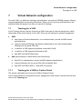
7 Virtual Network configuration. . . . . . . . . . . . . . . . . . . . . . . . . . . . . . . . . . . . . . . . . . .
7.1 Topology for a VNS. . . . . . . . . . . . . . . . . . . . . . . . . . . . . . . . . . . . . . . . . . . . . . . . . . .
7.1.1 Topology for a VNS for Captive Portal . . . . . . . . . . . . . . . . . . . . . . . . . . . . . . . . .
7.1.2 Topology for a VNS for AAA. . . . . . . . . . . . . . . . . . . . . . . . . . . . . . . . . . . . . . . . .
7.2 Authentication for a VNS. . . . . . . . . . . . . . . . . . . . . . . . . . . . . . . . . . . . . . . . . . . . . . .
7.2.1 Authentication for a VNS for Captive Portal . . . . . . . . . . . . . . . . . . . . . . . . . . . . .
7.2.1.1 Configure Captive Portal for internal or external authentication . . . . . . . . . .
7.2.2 Authentication for a VNS for AAA. . . . . . . . . . . . . . . . . . . . . . . . . . . . . . . . . . . . .
7.2.3 MAC-based authentication for a VNS. . . . . . . . . . . . . . . . . . . . . . . . . . . . . . . . . .
7.3 Accounting for a VNS . . . . . . . . . . . . . . . . . . . . . . . . . . . . . . . . . . . . . . . . . . . . . . . . .
7.4 RADIUS Policy for a VNS . . . . . . . . . . . . . . . . . . . . . . . . . . . . . . . . . . . . . . . . . . . . . .
7.4.1 RADIUS Policy for Captive Portal. . . . . . . . . . . . . . . . . . . . . . . . . . . . . . . . . . . . .
7.4.2 RADIUS Policy for AAA and AAA groups. . . . . . . . . . . . . . . . . . . . . . . . . . . . . . .
7-73
7-73
7-73
7-77
7-78
7-80
7-83
7-85
7-86
7-87
7-88
7-89
7-89
2
A31003-W1010-A100-1-7619, July 2005
HiPath Wireless Controller, Access Points and Convergence Software V3.0:, User Guide
HWC_User_GuideTOC.fm
Nur für den internen Gebrauch
Content
7.5 Filtering rules for a VNS. . . . . . . . . . . . . . . . . . . . . . . . . . . . . . . . . . . . . . . . . . . . . . . 7-90
7.5.1 Filtering rules for an exception filter . . . . . . . . . . . . . . . . . . . . . . . . . . . . . . . . . . 7-91
7.5.2 The non-authenticated filter for Captive Portal . . . . . . . . . . . . . . . . . . . . . . . . . . 7-92
7.5.3 Filtering rules for a Filter ID group. . . . . . . . . . . . . . . . . . . . . . . . . . . . . . . . . . . . 7-94
7.5.4 Filtering rules for a default filter . . . . . . . . . . . . . . . . . . . . . . . . . . . . . . . . . . . . . . 7-96
7.5.4.1 Filtering Rules for an AAA Group VNS . . . . . . . . . . . . . . . . . . . . . . . . . . . . . 7-98
7.5.4.2 Filtering rules between two wireless devices . . . . . . . . . . . . . . . . . . . . . . . . 7-98
7.6 Multicast for a VNS . . . . . . . . . . . . . . . . . . . . . . . . . . . . . . . . . . . . . . . . . . . . . . . . . . 7-99
7.7 Privacy for a VNS . . . . . . . . . . . . . . . . . . . . . . . . . . . . . . . . . . . . . . . . . . . . . . . . . . 7-100
7.7.1 Privacy for a VNS for Captive Portal . . . . . . . . . . . . . . . . . . . . . . . . . . . . . . . . . 7-100
7.7.2 Privacy for a VNS for AAA. . . . . . . . . . . . . . . . . . . . . . . . . . . . . . . . . . . . . . . . . 7-102
7.8 A VNS with no authentication . . . . . . . . . . . . . . . . . . . . . . . . . . . . . . . . . . . . . . . . . 7-105
7.9 A VNS for voice traffic . . . . . . . . . . . . . . . . . . . . . . . . . . . . . . . . . . . . . . . . . . . . . . . 7-105
8 HiPath Wireless Controller Configuration: Availability and Mobility. . . . . . . . . .
8.1 Availability . . . . . . . . . . . . . . . . . . . . . . . . . . . . . . . . . . . . . . . . . . . . . . . . . . . . . . . .
8.2 Mobility and the VN Manager . . . . . . . . . . . . . . . . . . . . . . . . . . . . . . . . . . . . . . . . .
8.2.1 VN Manager and VN Agent: Background . . . . . . . . . . . . . . . . . . . . . . . . . . . . .
8-109
8-109
8-113
8-114
9 HiPath Wireless Controller: configuring other functions . . . . . . . . . . . . . . . . . . .
9.1 Management users . . . . . . . . . . . . . . . . . . . . . . . . . . . . . . . . . . . . . . . . . . . . . . . . .
9.2 Network time . . . . . . . . . . . . . . . . . . . . . . . . . . . . . . . . . . . . . . . . . . . . . . . . . . . . . .
9.3 Check Point event logging . . . . . . . . . . . . . . . . . . . . . . . . . . . . . . . . . . . . . . . . . . . .
9.4 Setting up SNMP . . . . . . . . . . . . . . . . . . . . . . . . . . . . . . . . . . . . . . . . . . . . . . . . . . .
9.4.1 MIB support . . . . . . . . . . . . . . . . . . . . . . . . . . . . . . . . . . . . . . . . . . . . . . . . . . . .
9.4.2 Enabling SNMP on the HiPath Wireless Controller. . . . . . . . . . . . . . . . . . . . . .
9-117
9-117
9-118
9-119
9-121
9-121
9-122
10 Setting up third-party access points. . . . . . . . . . . . . . . . . . . . . . . . . . . . . . . . . . 10-125
11 Mitigator: detecting rogue access points. . . . . . . . . . . . . . . . . . . . . . . . . . . . . .
11.1 Overview . . . . . . . . . . . . . . . . . . . . . . . . . . . . . . . . . . . . . . . . . . . . . . . . . . . . . . .
11.2 Enabling the Analysis and RFDC Engines. . . . . . . . . . . . . . . . . . . . . . . . . . . . . .
11.3 Mitigator: running scans. . . . . . . . . . . . . . . . . . . . . . . . . . . . . . . . . . . . . . . . . . . .
11.4 The Analysis Engine . . . . . . . . . . . . . . . . . . . . . . . . . . . . . . . . . . . . . . . . . . . . . .
11.5 Viewing the Scanner Status report . . . . . . . . . . . . . . . . . . . . . . . . . . . . . . . . . . .
11-129
11-129
11-130
11-131
11-133
11-137
12 Ongoing operation . . . . . . . . . . . . . . . . . . . . . . . . . . . . . . . . . . . . . . . . . . . . . . . .
12.1 Wireless AP maintenance: software . . . . . . . . . . . . . . . . . . . . . . . . . . . . . . . . . .
12.2 Wireless AP client management . . . . . . . . . . . . . . . . . . . . . . . . . . . . . . . . . . . . .
12.2.1 Client disassociate . . . . . . . . . . . . . . . . . . . . . . . . . . . . . . . . . . . . . . . . . . . .
12.2.2 Client blacklist . . . . . . . . . . . . . . . . . . . . . . . . . . . . . . . . . . . . . . . . . . . . . . . .
12.3 HiPath Wireless Controller software maintenance. . . . . . . . . . . . . . . . . . . . . . . .
12.4 Controller, Access Points and Convergence Software logs and traces. . . . . . . .
12.4.1 Viewing log, alarm and trace messages . . . . . . . . . . . . . . . . . . . . . . . . . . . .
12.5 Reports and displays . . . . . . . . . . . . . . . . . . . . . . . . . . . . . . . . . . . . . . . . . . . . . .
12.5.1 View displays . . . . . . . . . . . . . . . . . . . . . . . . . . . . . . . . . . . . . . . . . . . . . . . .
12.5.2 View reports . . . . . . . . . . . . . . . . . . . . . . . . . . . . . . . . . . . . . . . . . . . . . . . . .
12-139
12-139
12-141
12-142
12-143
12-146
12-149
12-149
12-152
12-152
12-154
A31003-W1010-A100-1-7619, July 2005
HiPath Wireless Controller, Access Points and Convergence Software V3.0: User Guide
3
HWC_User_GuideTOC.fm
Content
Nur für den internen Gebrauch
13 Glossary . . . . . . . . . . . . . . . . . . . . . . . . . . . . . . . . . . . . . . . . . . . . . . . . . . . . . . . . . 13-155
13.1 Networking terms and abbreviations. . . . . . . . . . . . . . . . . . . . . . . . . . . . . . . . . . . 13-155
13.2 Controller, Access Points and Convergence Software terms and abbreviations . 13-175
A Controller, Access Points and Convergence Software system states and LEDs A-177
A.1 HiPath Wireless Controller system states and LEDs . . . . . . . . . . . . . . . . . . . . . . . . A-177
A.2 Wireless AP system states . . . . . . . . . . . . . . . . . . . . . . . . . . . . . . . . . . . . . . . . . . . . A-178
B CLI command reference . . . . . . . . . . . . . . . . . . . . . . . . . . . . . . . . . . . . . . . . . . . . . . B-181
C DHCP, SLP, and Option 78 reference . . . . . . . . . . . . . . . . . . . . . . . . . . . . . . . . . . .
C.1 Service Location Protocol (SLP) (RFC2608) . . . . . . . . . . . . . . . . . . . . . . . . . . . . . .
C.2 DHCP Options for Service Location Protocol (RFC2610) . . . . . . . . . . . . . . . . . . . .
C.3 SLP Directory Agent Option (Option 78) . . . . . . . . . . . . . . . . . . . . . . . . . . . . . . . . .
C.4 SLP Service Scope Option (Option 79) . . . . . . . . . . . . . . . . . . . . . . . . . . . . . . . . . .
C-187
C-188
C-188
C-188
C-189
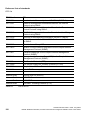
D Reference lists of standards . . . . . . . . . . . . . . . . . . . . . . . . . . . . . . . . . . . . . . . . . . D-191
D.1 RFC list. . . . . . . . . . . . . . . . . . . . . . . . . . . . . . . . . . . . . . . . . . . . . . . . . . . . . . . . . . . D-191
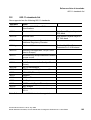
D.2 802.11 standards list . . . . . . . . . . . . . . . . . . . . . . . . . . . . . . . . . . . . . . . . . . . . . . . . D-193
E Support for Wireless AP . . . . . . . . . . . . . . . . . . . . . . . . . . . . . . . . . . . . . . . . . . . . . . A-195
E.1 Wireless AP diagnostics by Telnet . . . . . . . . . . . . . . . . . . . . . . . . . . . . . . . . . . . . . . A-195
F RADIUS Attributes . . . . . . . . . . . . . . . . . . . . . . . . . . . . . . . . . . . . . . . . . . . . . . . . . . . A-197
F.1 RADIUS Vendor-Specific Attributes (VSAs) . . . . . . . . . . . . . . . . . . . . . . . . . . . . . . . A-197
F.2 RADIUS Accounting . . . . . . . . . . . . . . . . . . . . . . . . . . . . . . . . . . . . . . . . . . . . . . . . . A-198
G Logs and Events . . . . . . . . . . . . . . . . . . . . . . . . . . . . . . . . . . . . . . . . . . . . . . . . . . . .
G.1 Overview . . . . . . . . . . . . . . . . . . . . . . . . . . . . . . . . . . . . . . . . . . . . . . . . . . . . . . . . .
G.2 Critical . . . . . . . . . . . . . . . . . . . . . . . . . . . . . . . . . . . . . . . . . . . . . . . . . . . . . . . . . . .
G.3 Major . . . . . . . . . . . . . . . . . . . . . . . . . . . . . . . . . . . . . . . . . . . . . . . . . . . . . . . . . . . .
4
A-201
A-201
A-202
A-223
A31003-W1010-A100-1-7619, July 2005
HiPath Wireless Controller, Access Points and Convergence Software V3.0:, User Guide
HWC_Pref.fm
About this Guide
Who should use this guide
1
About this Guide
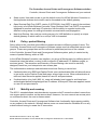
This guide describes how to install, configure, and manage the Controller, Access Points and
Convergence Software software.
1.1
Who should use this guide
This guide is a reference for system administrators who install and manage the Controller,
Access Points and Convergence Software.
1.2
What is in this guide
This guide contains the following chapters:
●
Chapter 1, “About this Guide”, describes the target audience and content of the guide, the
formatting conventions used in it, and how to provide feedback on the guide.
●
Chapter 2, “The Controller, Access Points and Convergence Software solution”, provides
an overview of the product, its features and functionality.
●
Chapter 3, “HiPath Wireless Controller: Startup”, describes how to perform the installation
and first-time setup of the HiPath Wireless Controller.
●
Chapter 4, “Controller, Access Points and Convergence Software configuration”, describes
setting up the initial configuration, as well as configuring the data ports and defining
routing.
●
Chapter 5, “Wireless AP: startup”, tells how to install the Wireless AP, how it discovers and
registers with the HiPath Wireless Controller, how to view and modify the radio
configuration, and how to enable Dynamic Radio Frequency Management.
●
Chapter 6, “Virtual network services (VNS): Introduction”, provides an overview of Virtual
Network Services (VNS), the mechanism by which the Controller, Access Points and
Convergence Software controls and manages network access.
●
Chapter 7, “Virtual Network configuration”, gives detailed instructions in how to configure
a VNS, its topology, authentication, accounting, RADIUS policy, multicast, filtering and
privacy. Both Captive Portal and AAA types of VNS are described.
●
Chapter 8, “HiPath Wireless Controller Configuration: Availability and Mobility”, describes
how to set up the features that provide availability in the event of a Controller failover, and
mobility for a wireless device user.
●
Chapter 9, “HiPath Wireless Controller: configuring other functions”, includes functions
such as user privileges, network time, Check Point event logging and SNMP.
A31003-W1010-A100-1-7619, July 2005
HiPath Wireless Controller, Access Points and Convergence Software V3.0: User Guide
5
HWC_Pref.fm
About this Guide
Formatting conventions
●
Chapter 10, “Setting up third-party access points”, describes how to use the Controller,
Access Points and Convergence Software features with third-party wireless APs.
●
Chapter 11, “Mitigator: detecting rogue access points”, explains the security tool that scans
for, detects and reports on rogue access points.
●
Chapter 12, “Ongoing operation”, describes maintenance activities, such as software
upgrades on both the HiPath Wireless Controller and the Wireless AP. This chapter also
includes information on the logs, traces, reports and displays available.
●
Appendix A, “Controller, Access Points and Convergence Software system states and
LEDs”, provides a reference on the LED displays and their significance.
●
Appendix B, “CLI command reference”, provides a list of the CLI command line syntax.
●
Appendix C, “DHCP, SLP, and Option 78 reference”, provides background information on
how the discovery process uses these network services.
●
Appendix D, “Reference lists of standards”, provides a reference list of RFCs supported.
●
Appendix E, “Support for Wireless AP”, provides information on a support tool.
●
Appendix F, “RADIUS Attributes”, provides a reference list of the RADIUS Attributes that
are supported by the Controller, Access Points and Convergence Software.
●
Appendix G, “Logs and Events”, provides a reference list of the log and event messages.
This guide also contains a glossary of standard industry terms used in this guide.
1.3
Formatting conventions
The Controller, Access Points and Convergence Software documentation uses the following
formatting conventions to make it easier to find information and follow procedures:
●
Bold text is used to identify components of the management interface, such as menu items
and section of pages, as well as the names of buttons and text boxes.
For example: Click Logout.
●
Monospace font is used in code examples and to indicate text that you type.
For example: Type https://<hls-address>[:mgmt-port>]
●
The following symbols are used to draw your attention to additional information:
>
6
Notes identify useful information that is not essential, such as reminders, tips, or
other ways to perform a task.
A31003-W1010-A100-1-7619, July 2005
HiPath Wireless Controller, Access Points and Convergence Software V3.0: User Guide
HWC_Pref.fm
About this Guide
Documentation feedback
7
1.4
Warnings identify essential information. Ignoring a warning can lead to problems
with the application.
Documentation feedback
If you have any problems using this document, please contact your next level of support:
●
Siemens employees should contact the interactive Customer Engagement Team (i-CET).
●
Customers should contact the Siemens Customer Support Center.
When you call, please have the following information ready. This will help us to identify the
document that you are referring to.
●
Title: HiPath Wireless Controller, Access Points and Convergence Software V3.0: User
Guide
●
Part Number: A31003-W1010-A100-1-7619
1.5
Protocols and standards
Appendix D, “Reference lists of standards” lists the protocols and standards supported by the
Controller, Access Points and Convergence Software. These lists include the Requests for
Comment (RFCs) of the Internet Engineering Task Force (IETF) and the 802.11 standards
developed by the Institute of Electrical and Electronics Engineers (IEEE).
1.6
Regulatory information
Below is regulatory information for the HiPath Wireless Controller and the Wireless APs.
7
1.6.1
Changes or modifications made to the HiPath Wireless Controller or the Wireless
APs which are not expressly approved by the party responsible for compliance could
void the user's authority to operate the equipment.
Safety
Wireless AP (AP2610 and AP2620):
●
IEC 60959-1
●
EN 60950-1
●
UL 60950-1
●
CAN/CSA C22.2 No.60950-1-03
A31003-W1010-A100-1-7619, July 2005
HiPath Wireless Controller, Access Points and Convergence Software V3.0: User Guide
7
HWC_Pref.fm
About this Guide
Regulatory information
HiPath Wireless Controller (C10, C100 and C1000):
●
IEC 60959-1
●
EN 60950-1
●
UL 60950-1
●
CAN/CSA C22.2 No.60950-1-03
1.6.2
Emissions
Wireless AP (AP2610 and AP2620):
●
FCC Part 15, Subpart B, Class B
●
ICES-003, Class B
●
EN 55011 (CISPR 11) Class B, Group 1 / EN 55022 (CISPR 22) Class B
●
EN/UL60601-1-2 (EMC immunity for medical equipment)
●
EN 301 489-1 & -17
●
EN 50385 (EMF)
HiPath Wireless Controller (C10, C100 and C1000):
●
FCC Part 15, Subpart B, Class A
●
ICES-003, Class A
●
EN 55022 (CISPR22), Class A
●
EN 55024 (CISPR 24)
1.6.3
Radio
Wireless AP (AP2610 and AP2620):
●
FCC Parts 15.247 (Operation in 2.412-2.462 GHz and 5.725-5.825 GHz)
●
FCC Parts 15.407 Subpart e (Operation in 5.15-5.35 GHz band)
●
RSS-210 (Operation in 2.412-2.462 GHz and 5.725-5.825 GHz)
●
EN 300 328 (2.412-2.472 GHz)
●
EN 301 893 (5.150-5.350 GHz and 5.470-5.725 GHz)
8
A31003-W1010-A100-1-7619, July 2005
HiPath Wireless Controller, Access Points and Convergence Software V3.0: User Guide
HWC_Pref.fm
About this Guide
Regulatory information
1.6.4
Other Approvals
Wireless AP (AP2610 and AP2620):
●
UL 2043 (Fire Test for Heat and Visible Smoke) meets plenum rating requirements for use
in air-handling spaces
A31003-W1010-A100-1-7619, July 2005
HiPath Wireless Controller, Access Points and Convergence Software V3.0: User Guide
9
HWC_Pref.fm
About this Guide
Regulatory information
10
A31003-W1010-A100-1-7619, July 2005
HiPath Wireless Controller, Access Points and Convergence Software V3.0: User Guide
HWC_Intro.fm
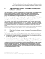
The Controller, Access Points and Convergence Software solution
What is the Controller, Access Points and Convergence Software system?
2
The Controller, Access Points and Convergence
Software solution
The next generation of Siemens wireless networking devices provides a truly scalable WLAN
solution. Siemens Wireless APs are thin access points that are controlled through a
sophisticated network device, the HiPath Wireless Controller. This solution provides the
security and manageability required by enterprises and service providers alike.
The Controller, Access Points and Convergence Software system is a highly scalable wireless
local area network (WLAN) solution developed by Siemens. Based on a third generation WLAN
topology, the Controller, Access Points and Convergence Software system makes wireless
practical for medium and large-scale enterprises and for service providers.
The Controller, Access Points and Convergence Software system provides a secure, highly
scalable, cost-effective solution based on the IEEE 802.11standard. The solution is intended
for enterprise networks operating on many floors in more than one building, as well as in public
environments such as airports and convention centers that require more than two access
points.
This section provides an overview of the fundamental principles of the Controller, Access Points
and Convergence Software system: what it is, how it works, and its advantages.
2.1
What is the Controller, Access Points and Convergence Software
system?
The Controller, Access Points and Convergence Software system replaces the conventional
access points used in wireless networking with two network devices that work as a system:
●
HiPath Wireless Controller: A network device that provides smart centralized control over
the elements (Wireless APs) in the wireless network.
●
Wireless APs: The access points for 802.11 clients (wireless devices) in the network,
controlled by the HiPath Wireless Controller. The Wireless AP is a “fit access point”
because its wireless control is handled by the HiPath Wireless Controller. The Wireless AP
is a dual-band access point, with both 802.11a and 802.11b/g radios.
Together, the Controller, Access Points and Convergence Software products enable a radically
simplified new approach to setting up, administering and maintaining a WLAN. Controller,
Access Points and Convergence Software provides a Layer 3 IP routed WLAN architecture.
This architecture can be implemented over several subnets without requiring the configuration
of virtual local area networks (VLANs).
A31003-W1010-A100-1-7619, July 2005
HiPath Wireless Controller, Access Points and Convergence Software V3.0: User Guide
11
HWC_Intro.fm
The Controller, Access Points and Convergence Software solution
What is the Controller, Access Points and Convergence Software system?
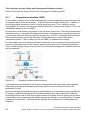
2.1.1
Conventional wireless LANS
At its simplest, wireless communication between two or more computers requires that each one
is equipped with a receiver/transmitter – a WLAN Network Interface Card (NIC) – capable of
exchanging digital information over a common radio frequency. This is called an ad hoc
configuration. An ad hoc network allows wireless devices to communicate together. This is an
independent basic service set (IBSS).
An alternative to the ad hoc configuration is the use of an access point. This may be a dedicated
hardware router or a computer running special software. Computers and other wireless devices
communicate with each other through this access point. The 802.11 standard defines Access
Point communications as devices that allow wireless devices to communicate with a
“distribution system”. This is a basic service set (BSS) or infrastructure network.
For the wireless devices to communicate with computers on a wired network, the access points
must be connected into the wired network, and provide access to the networked computers.
This is called bridging. Clearly, there are security issues and management scalability issues in
this arrangement.
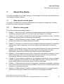
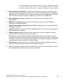
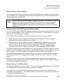
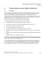
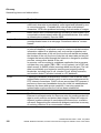
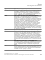
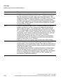
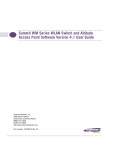
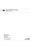
Figure 2-1
Standard wireless network solution
The wireless devices and the wired networks communicate with each other using standard
networking protocols and addressing schemes. Most commonly, Internet Protocol (IP)
addressing is used.
While this topology works well enough for small installations, as the network grows the difficulty
of setting up and administering all the individual access points expands as well. When the
expanding network has to cope with a large number of wireless users all signing on and off at
random times, the complexity grows rapidly. Imagine, for example, a university library filled with
professors and students – all equipped with laptops. Or a conference full of delegates and
exhibitors.
12
A31003-W1010-A100-1-7619, July 2005
HiPath Wireless Controller, Access Points and Convergence Software V3.0: User Guide
HWC_Intro.fm
The Controller, Access Points and Convergence Software solution
What is the Controller, Access Points and Convergence Software system?
Clearly, there must be a better way than setting up each access point individually.
2.1.2
The Controller, Access Points and Convergence Software
solution
The Controller, Access Points and Convergence Software solution consists of two devices:
●
The HiPath Wireless Controller is a rack-mountable network device designed to be
integrated into an existing wired Local Area Network (LAN). It provides centralized control
over all access points (both Wireless APs and third-party access points) and manages the
network assignment of wireless device clients associating through access points.
●
The Wireless AP is a wireless LAN fit access point (IEEE 802.11) provided with unique
software that allows it to communicate only with a HiPath Wireless Controller. (A fit access
point handles the radio frequency (RF) communication but relies on a controller to handle
WLAN elements such as authentication.) The Wireless AP also provides local processing
such as encryption.
This architecture allows a single HiPath Wireless Controller to control many Wireless APs,
making the administration and management of large networks much easier.
There can be several HiPath Wireless Controllers in the network, each with its set of registered
Wireless APs. The HiPath Wireless Controllers can also act as backups to each other, providing
stable network availability.
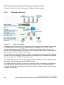
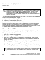
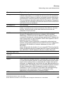
In addition to the HiPath Wireless Controllers and Wireless APs, the solution requires three
other components, which are standard for enterprise and service provider networks:
●
RADIUS Server (Remote Access Dial-In User Service) (RFC2865 and RFC2866), or other
authentication server. Assigns and manages ID and Password protection throughout the
network. Used for authentication of the wireless users.
●
DHCP Server (Dynamic Host Configuration Protocol) (RFC2131). Assigns IP addresses,
gateways and subnet masks dynamically. Also used by the Wireless APs to discover the
location of the HiPath Wireless Controller during the initial registration process.
●
SLP (Service Location Protocol) (RFC2608) supported on the DHCP server, when SLP is
used as part of the discovery mechanism.
A31003-W1010-A100-1-7619, July 2005
HiPath Wireless Controller, Access Points and Convergence Software V3.0: User Guide
13
HWC_Intro.fm
The Controller, Access Points and Convergence Software solution
What is the Controller, Access Points and Convergence Software system?
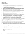
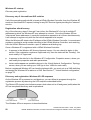
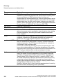
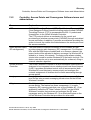
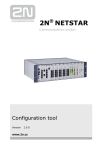
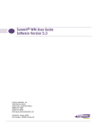
Figure 2-2
Controller, Access Points and Convergence Software solution
The HiPath Wireless Controller appears to the existing network as if it were an access point,
but in fact one HiPath Wireless Controller controls many Wireless APs.
The HiPath Wireless Controller has built-in capabilities to recognize and manage the Wireless
APs. The HiPath Wireless Controller activates the Wireless APs, enables them to receive
wireless traffic from wireless devices, processes the data traffic from the Wireless APs and
forwards or routes that data traffic out to the network. This processing includes authenticating
requests and applying access policies.
Simplifying the Wireless APs makes them:
●
cost-effective
●
easy to manage
●
easy to deploy
Putting control on an intelligent centralized HiPath Wireless Controller enables:
●
centralized configuration, management, reporting, maintenance
●
high security
●
flexibility to suit enterprise
●
scalable and resilient deployments with a few HiPath Wireless Controllers controlling
hundreds of Wireless APs
Here are some of the Controller, Access Points and Convergence Software system
advantages:
14
A31003-W1010-A100-1-7619, July 2005
HiPath Wireless Controller, Access Points and Convergence Software V3.0: User Guide
HWC_Intro.fm
The Controller, Access Points and Convergence Software solution
What is the Controller, Access Points and Convergence Software system?
Scales up to
Enterprise capacity
One HiPath Wireless Controller controls as many as 200 Wireless
APs. In turn each Wireless AP can handle up to 254 wireless
devices. With additional HiPath Wireless Controllers, the number of
wireless devices the system can support is in the thousands.
Integrates in existing
network
A HiPath Wireless Controller can be added to an existing enterprise
network as a new network device, greatly enhancing its capability
without interfering with existing functionality. Integration of the
HiPath Wireless Controllers and Wireless APs does not require any
reconfiguration of the existing infrastructure (e.g., VLANs).
Offers centralized
management and
control
An administrator accesses the HiPath Wireless Controller in its
centralized location to monitor and administer the entire wireless
network. The HiPath Wireless Controller has functionality to
recognize, configure, and manage the Wireless APs and distribute
new software releases.
Provides easy
deployment of
Wireless APs
The initial configuration of the Wireless APs on the centralized
HiPath Wireless Controller can be done with an automatic
“discovery” technique.
Provides security via
user authentication
Controller, Access Points and Convergence Software uses existing
authentication (AAA) servers to authenticate and authorize users.
Provides security via
filters and privileges
Controller, Access Points and Convergence Software uses virtual
networking techniques to create separate virtual networks with
defined authentication and billing services, access policies and
privileges.
Supports seamless
mobility and roaming
Controller, Access Points and Convergence Software supports
seamless roaming of a wireless device from one Wireless AP to
another on the same HiPath Wireless Controller or on a different
HiPath Wireless Controller.
Integrates third-party
access points
Controller, Access Points and Convergence Software can integrate
legacy third-party access points, using a combination of network
routing and authentication techniques.
Prevents rogue
devices
Unauthorized access points will be detected and identified as
harmless or dangerous rogue APs.
Provides accounting
services
Controller, Access Points and Convergence Software logs wireless
user sessions, user group activity, and other activity reporting,
enabling the generation of consolidated billing records.
Table 2-1
Advantages of the Controller, Access Points and Convergence Software
system
A31003-W1010-A100-1-7619, July 2005
HiPath Wireless Controller, Access Points and Convergence Software V3.0: User Guide
15
HWC_Intro.fm
The Controller, Access Points and Convergence Software solution
Controller, Access Points and Convergence Software and your network
Offers troubleshooting Controller, Access Points and Convergence Software logs system
capability
and session activity and provides reports to aid in troubleshooting
analysis.
Offers dynamic RF
management
Table 2-1
Controller, Access Points and Convergence Software can
automatically select channels and adjust Radio Frequency (RF)
signal propagation power levels without user intervention.
Advantages of the Controller, Access Points and Convergence Software
system
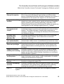
2.2
Controller, Access Points and Convergence Software and your
network
2.2.1
Components of the solution: a summary
The following is a summary checklist of the components of the Controller, Access Points and
Convergence Software solution on your enterprise network. These are described in detail in
this guide.
●
The HiPath Wireless Controller, providing centralized control over all access points (both
Wireless APs and third-party access points) and manages the network assignment of
wireless device clients associating through access points.
●
The Wireless AP is a wireless LAN thin access point (IEEE 802.11) that communicates
only with a HiPath Wireless Controller.
●
RADIUS Server (Remote Access Dial-In User Service) (RFC2865), or other
authentication server. Assigns and manages ID and Password protection throughout the
network. Used for authentication of the wireless users in either 802.1x or Captive Port
security modes.
The RADIUS Server system can be set up for certain standard attributes, such as FilterID, and for the Vendor Specific Attributes (VSAs).
●
DHCP Server (Dynamic Host Configuration Protocol) (RFC2131). Assigns IP addresses,
gateways and subnet masks dynamically. IP address assignment for clients can be done
by the DCHP server internal to the HiPath Wireless Controller, or by existing servers using
DHCP relay. Also used by the Wireless APs to discover the location of the HiPath Wireless
Controller during the initial registration process. For SLP, DHCP should have Option 78
enabled (Option 78 specifies the location of one or more SLP Directory Agents).
●
Service Location Protocol (SLP) (SLP RFC2608). Client applications are User Agents
and services are advertised by Service Agents. In larger installations, a Directory Agent
collects information from Service Agents and creates a central repository. The Siemens
solution relies on registering “siemens” as an SLP Service Agent.
16
A31003-W1010-A100-1-7619, July 2005
HiPath Wireless Controller, Access Points and Convergence Software V3.0: User Guide
HWC_Intro.fm
The Controller, Access Points and Convergence Software solution
Controller, Access Points and Convergence Software and your network
●
Domain Name Server (DNS), for an alternate mechanism (if present on the enterprise
network) for the automatic discovery process. Controller, Access Points and Convergence
Software relies on the DNS for Layer 3 deployments and for static configuration of Wireless
APs. The Siemens solution relies on registering "controller" as the DNS name.
●
Web Authentication Server, if desired for external Captive Portal and external
authentication.
●
RADIUS Accounting Server (Remote Access Dial-In User Service) (RFC2866), if
RADIUS Accounting is enabled.
●
Simple Network Management Protocol (SNMP) Manager Server, if forwarding SNMP
messages is enabled.
●
Check Point Server, Check Point Event Logging API (ELA), for security event logging if a
firewall application is enabled.
●
Network infrastructure, Ethernet switches and routers, must be configured to allow
routing between the various services noted above.
Routing must also be enabled between multiple HiPath Wireless Controllers, for such
Controller, Access Points and Convergence Software features as Availability, VN Manager
for mobility, Third-Party Access Points, and Mitigator for detection of rogue access points
(some features require the definition of static routes).
●
Web Browser, providing access to the HiPath Wireless Controller Management GUI to
configure Controller, Access Points and Convergence Software.
●
a device that supports SSH, for serial port access to the Command Line Interface (CLI), for
file management and monitoring by a network technician.
A31003-W1010-A100-1-7619, July 2005
HiPath Wireless Controller, Access Points and Convergence Software V3.0: User Guide
17
HWC_Intro.fm
The Controller, Access Points and Convergence Software solution
Controller, Access Points and Convergence Software and your network
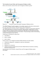
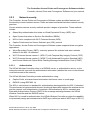
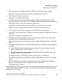
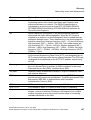
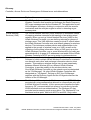
2.2.2
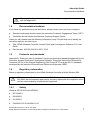
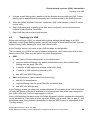
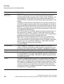
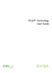
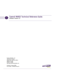
Figure 2-3
Network traffic flow
Traffic Flow diagram
The diagram above shows a simple configuration with a single HiPath Wireless Controller and
two Wireless APs, each supporting a wireless device. A RADIUS server on the network
provides authentication, and a DHCP server is used by the Wireless APs to discover the
location of the HiPath Wireless Controller during the initial registration process. Also present in
the network are routers and ethernet switches.
Each wireless device sends IP packets in the 802.11 standard to the Wireless AP. The Wireless
AP uses a UDP (User Datagram Protocol) based tunnelling protocol to encapsulate the packets
and forward them to the HiPath Wireless Controller.
The HiPath Wireless Controller decapsulates the packets, and routes these to destinations on
the network, after authentication by the RADIUS server.
The HiPath Wireless Controller functions like a standard router, except that it is configured to
route only network traffic associated with wireless connected users. The HiPath Wireless
Controller can also be configured to simply forward traffic to a default or static route if dynamic
routing is not preferred.
18
A31003-W1010-A100-1-7619, July 2005
HiPath Wireless Controller, Access Points and Convergence Software V3.0: User Guide
HWC_Intro.fm
The Controller, Access Points and Convergence Software solution
Controller, Access Points and Convergence Software and your network
2.2.3
Network security
The Controller, Access Points and Convergence Software system provides features and
functionality to control network access. These are based on standard wireless network security
practices.
Current wireless network security methods provide a degree of protection. These methods
include:
●
Shared Key authentication that relies on Wired Equivalent Privacy (WEP) keys
●
Open System that relies on Service Set Identifiers (SSIDs)
●
802.1x that is compliant with Wi-Fi Protected Access (WPA)
●
Captive Portal based on Secure Sockets Layer (SSL) protocol
The Controller, Access Points and Convergence Software system supports these encryption
approaches:
●
Wired Equivalent Privacy (WEP), a security protocol for wireless local area networks
defined in the 802.11b standard
●
Wi-Fi Protected Access version 1 (WPA1™) with Temporal Key Integrity Protocol (TKIP)
●
Wi-Fi Protected Access version 2 (WPA2™) with Advanced Encryption Standard (AES)
and Counter Mode with Cipher Block Chaining Message Authentication Code (CCMP).
2.2.3.1
Authentication
The HiPath Wireless Controller relies on a RADIUS server, or authentication server, on the
enterprise network to provide the authentication information (whether the user is to be allowed
or denied access to the network).
The HiPath Wireless Controller provides authentication using:
●
Captive Portal, a browser-based mechanism that forces users to a web page
●
RADIUS (using IEEE 802.1x)
The 802.1x mechanism is a standard for authentication developed within the 802.11 standard.
This mechanism is implemented at the port, blocking all data traffic between the wireless device
and the network until authentication is complete. Authentication by 802.1x standard uses
Extensible Authentication Protocol (EAP) for the message exchange between the HiPath
Wireless Controller and the RADIUS server.
When 802.1x is used for authentication, the HiPath Wireless Controller provides the capability
to dynamically assign per-wireless-device WEP keys (called per-station WEP keys in 802.11).
A31003-W1010-A100-1-7619, July 2005
HiPath Wireless Controller, Access Points and Convergence Software V3.0: User Guide
19
HWC_Intro.fm
The Controller, Access Points and Convergence Software solution
Controller, Access Points and Convergence Software and your network
In Controller, Access Points and Convergence Software, a RADIUS redundancy feature is
provided, where you can define a failover RADIUS server (up to 2 servers) in the event that the
active RADIUS server fails.
2.2.3.2
Privacy
Privacy is a mechanism that protects data over wireless and wired networks, usually by
encryption techniques.
Controller, Access Points and Convergence Software supports the Wired Equivalent Privacy
(WEP) standard common to conventional access points.
It also provides Wi-Fi Protected Access version 1 (WPA v.1) encryption, based on Pairwise
Master Key (PMK) and Temporal Key Integrity Protocol (TKIP). The most secure encryption
mechanism is WPA version 2 using Advanced Encryption Standard (AES).
2.2.4
Interaction with wired networks: Virtual Network Services
Controller, Access Points and Convergence Software provides a versatile means of mapping
wireless networks to the topology of an existing wired network. This is accomplished through
the assignment of Virtual Network Services.
When you set up Virtual Network Services (VNS) on the HiPath Wireless Controller, you are
defining subnets for groups of wireless users. This VNS definition creates a virtual IP subnet
where the HiPath Wireless Controller acts as a default gateway for wireless devices.
This technique enables policies and authentication to be applied to the groups of wireless users
on a VNS, as well as the collecting of accounting information on user sessions that can be used
for billing.
When a VNS is set up on the HiPath Wireless Controller:
●
one or more Wireless APs (by radio) are associated with it
●
a range of IP addresses is set aside for the HiPath Wireless Controller’s DHCP server to
assign to wireless devices
If routing protocol is enabled, the HiPath Wireless Controller advertises the VNS as a routable
network segment to the wired network, and routes traffic between the wireless devices and the
wired network.
Each radio on a Wireless AP can participate in up to four VNSs, via the multi-SSID function.
2.2.5
Static routing and routing protocols
Routing can be used on the HiPath Wireless Controller to support the VNS definitions.
In the User Interface, you can configure routing on the HiPath Wireless Controller to use one
of the following routing techniques:
20
A31003-W1010-A100-1-7619, July 2005
HiPath Wireless Controller, Access Points and Convergence Software V3.0: User Guide
HWC_Intro.fm
The Controller, Access Points and Convergence Software solution
Controller, Access Points and Convergence Software and your network
●
Static routes: Use static routes to set the default route of a HiPath Wireless Controller so
that legitimate wireless device traffic can be forwarded to the default gateway.
●
Open Shortest Path First (OSPF, version 2) (RFC2328): Use OSPF to specify the next best
hop (route) of a HiPath Wireless Controller. Open Shortest Path First (OSPF) is a protocol
designed for medium and large IP networks, with the ability to segment routers into
different routing areas for routing information summarization and propagation.
●
Next Hop Routing: Use next hop routing as part of a VNS definition to specify a unique
default gateway to which traffic on a unique VNS is forwarded
2.2.6
Policy: packet filtering
Policy refers to the rules that allow different network access to different groups of users. The
Controller, Access Points and Convergence Software system can link authorized users to user
groups. These user groups then can be confined to predefined portions of the network.
In the Controller, Access Points and Convergence Software system, policy is carried out by
means of packet filtering, within a VNS.
In the HiPath Wireless Controller user interface, you set up a filtering policy by defining a set of
hierarchical rules that allow (or deny) traffic to specific IP addresses, IP address ranges, or
services (ports). The sequence and hierarchy of these filtering rules must be carefully
designed, based on your enterprise’s user access plan.
The authentication technique selected determines how filtering is carried out:
●
If authentication is by SSID and Captive Portal, a non-authenticated filter will allow all users
to get as far as the Captive Portal web page, where login occurs. When authentication is
returned, then filters are applied, based on user ID and permissions.
●
If authentication is by AAA (802.1x), users will already have logged in and have been
authenticated before being assigned an IP address. At this point, filters are applied, based
on user ID and permissions.
2.2.7
Mobility and roaming
The 802.11 standard allows a wireless device to preserve its IP connection when it roams from
one access point to another on the same subnet. However, if a user roams to an access point
on a different subnet, the user is disconnected.
Controller, Access Points and Convergence Software has functionality that supports mobility
on any subnet in the network. Wireless device users can roam between Wireless APs on any
subnet without having to renew the IP connection.
A31003-W1010-A100-1-7619, July 2005
HiPath Wireless Controller, Access Points and Convergence Software V3.0: User Guide
21
HWC_Intro.fm
The Controller, Access Points and Convergence Software solution
Controller, Access Points and Convergence Software and your network
The HiPath Wireless Controller stores the wireless device’s current session information, such
as IP address and MAC address. If the wireless device has not disassociated, then when it
requests network access on a different Wireless AP, the HiPath Wireless Controller can match
its session information and recognize it as still in a current session.
In addition, a HiPath Wireless Controller can learn about other HiPath Wireless Controllers on
the network, and then exchange client session information. This enables a wireless device user
to roam seamlessly between different Wireless APs on different HiPath Wireless Controllers.
2.2.8
Availability
Controller, Access Points and Convergence Software provides seamless availability against
Wireless AP outages, HiPath Wireless Controller outages, and even network outages.
For example, if one Wireless AP fails, coverage for the wireless device is automatically provided
by the next nearest Wireless AP.
If a HiPath Wireless Controller fails, all of its associated Wireless APs, or access points, can
automatically migrate to another HiPath Wireless Controller that has been defined as the
secondary or backup HiPath Wireless Controller. When the original HiPath Wireless Controller
returns to the network, the Wireless APs automatically re-establish their normal connection
with their original HiPath Wireless Controller.
2.2.9
Quality of Service (QoS)
Controller, Access Points and Convergence Software provides advanced Quality of Service
(QoS) management, in order to provide better network traffic flow. Such techniques include:
●
WMM (Wi-Fi Multimedia): enabled globally on the Wireless AP. For devices with WMM
enabled, the standard provides multimedia enhancements for audio, video, and voice
applications. WMM shortens the time between transmitting packets for higher priority
traffic. WMM is part of the 802.11e standard for QoS.
●
IP ToS (Type of Service) or DSCP (Diffserv Codepoint): the ToS/DSCP field in the IP
header of a frame is used to indicate the priority and Quality of Service for each frame. The
IP TOS and/or DSCP is maintained within CTP (CAPWAP Tunneling Protocol) by copying
the user IP QoS information to the CTP header — this is referred to as Adaptive QoS.
Quality of Service (QoS) management is also provided by:
●
assigning high priority to an SSID (configurable)
●
Adaptive QoS (automatic)
●
support for legacy devices that use SpectraLink Voice Protocol (SVP) for prioritizing voice
traffic (configurable)
22
A31003-W1010-A100-1-7619, July 2005
HiPath Wireless Controller, Access Points and Convergence Software V3.0: User Guide
HWC_Startup.fm
HiPath Wireless Controller: Startup
HiPath Wireless Controller features and installation
3
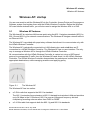
HiPath Wireless Controller: Startup
3.1
HiPath Wireless Controller features and installation
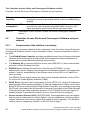
The HiPath Wireless Controller is a network device designed to be integrated into an existing
wired Local Area Network (LAN).
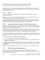
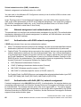
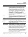
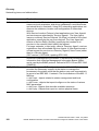
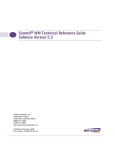
Figure 3-1
The HiPath Wireless Controller
The HiPath Wireless Controller provides centralized management, network access and routing
to wireless devices that are using Wireless APs to access the network. It can also be configured
to handle data traffic from third-party access points.
The HiPath Wireless Controller performs the following functions:
●
Controls and configures Wireless APs, providing centralized management
●
Authenticates wireless devices that contact a Wireless AP
●
Assigns each wireless device to a VNS when it connects
●
Routes traffic from wireless devices, using VNSs, to the wired network
●
Applies filtering policies to the wireless device session
●
Provides session logging and accounting capability
The HiPath Wireless Controller is rack-mountable. It comes in the following product families:
Model Number Specifications
HiPath
Wireless
Controller C10
●
●
●
●
HiPath
Wireless
Controller
C100
●
●
●
●
Four Fast-Ethernet ports, (10/100 BaseT), supporting up to 30
Wireless APs
One management port, (10/100 BaseT)
One console port (DB9 serial)
Power supply standard (S)
Four Fast-Ethernet ports, (10/100 BaseT), supporting up to 75
Wireless APs
One management port, (10/100 BaseT)
One console port (DB9 serial)
Power supply redundant (R)
A31003-W1010-A100-1-7619, July 2005
HiPath Wireless Controller, Access Points and Convergence Software V3.0: User Guide
23
HWC_Startup.fm
HiPath Wireless Controller: Startup
HiPath Wireless Controller features and installation
Model Number Specifications
HiPath
Wireless
Controller
C1000
●
●
●
●
3.1.1
Two GigE ports (dual 1GB SX network interfaces), supporting up to
200 Wireless APs
One management port, (10/100 BaseT)
One console port (DB9 serial)
Power supply redundant (R)
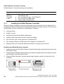
Installing the HiPath Wireless Controller
Before you begin installation, make sure that a site survey has been done, to determine the
number and location of Wireless APs and HiPath Wireless Controllers required. The site survey
should take a number of factors into consideration, including:
●
coverage areas
●
number of users
●
architectural features that affect transmission
●
existing wired network and access to ethernet cabling
●
type of mount (wall, ceiling, plenum) for Wireless APs
●
type of power (Power-over-Ethernet or AC adaptor) for Wireless APs
●
physical security of the HiPath Wireless Controller, including access control
Installing the HiPath Wireless Controller
1.
Unpack and mount the HiPath Wireless Controller following the detailed instructions in the
Quick Start Guide.
2.
Install the ferrite beads provided, black for the power cord and white for the ethernet cables,
as described in the Quick Start Guide.
3.
Plug the HiPath Wireless Controller power supply (single or dual) in to the back of the
Controller.
24
A31003-W1010-A100-1-7619, July 2005
HiPath Wireless Controller, Access Points and Convergence Software V3.0: User Guide
HWC_Startup.fm
HiPath Wireless Controller: Startup
First-time setup of HiPath Wireless Controller
4.
Perform initial setup of the HiPath Wireless Controller to change its factory default IP
address.
5.
After that, connect the HiPath Wireless Controller to the enterprise LAN.
3.2
First-time setup of HiPath Wireless Controller
3.2.1
Management port first-time setup
Before you can connect the HiPath Wireless Controller to the enterprise network, you must
change the IP address of the HiPath Wireless Controller management port from its factory
default to the IP address suitable for your enterprise network.
Access the HiPath Wireless Controller for initial setup by one of two methods:
●
a device supporting VT100 emulation such as a PC running HyperTerm, attached to the
HiPath Wireless Controller’s DB9 serial port (COM1 port) via a cross-over (null modem)
cable. The Command Line Interface (CLI) commands for the initial setup are described in
an attached appendix.
●
a laptop computer, running a web browser such as Internet Explorer 6.0 (or higher),
attached to the HiPath Wireless Controller’s ethernet Management Port (RJ45 port) via an
ethernet cross-over cable (cable provided with the HiPath Wireless Controller). The steps
for initial setup in the Graphical User Interface are described below.
The factory default management port setup of the HiPath Wireless Controller is:
Hostname:
HWC
Management Port IP address: 192.168.10.1:5825
Management Network Mask:
3.2.1.1
255.255.255.0
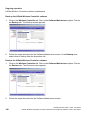
Changing the Management Port IP address: web browser method
1.
Connect a cross-over ethernet cable between the ethernet port of the laptop and ethernet
Management Port of the HiPath Wireless Controller.
2.
Statically assign an unused IP address in the 192.168.10.0/24 subnet for the ethernet port
of the PC (for example, 192.168.10.205).
3.
Run Internet Explorer (version 6.0 or above) or other web browser on the laptop.
A31003-W1010-A100-1-7619, July 2005
HiPath Wireless Controller, Access Points and Convergence Software V3.0: User Guide
25
HWC_Startup.fm
HiPath Wireless Controller: Startup
First-time setup of HiPath Wireless Controller
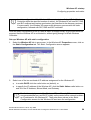
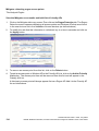
4.
Point the browser to the URL https://192.168.10.1:5825. This URL launches the webbased GUI on the HiPath Wireless Controller. The login screen appears.
5.
Key in the factory default User Name (“admin”) and Password (“abc123”). Click on the
Login button. The main menu screen appears.
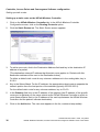
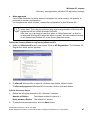
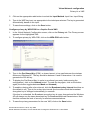
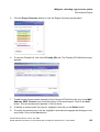
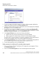
6.
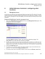
Click on the HiPath Wireless Controller Configuration menu option to navigate to the
HiPath Wireless Controller Configuration screen.
26
A31003-W1010-A100-1-7619, July 2005
HiPath Wireless Controller, Access Points and Convergence Software V3.0: User Guide
HWC_Startup.fm
HiPath Wireless Controller: Startup
First-time setup of HiPath Wireless Controller
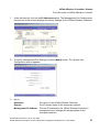
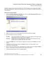
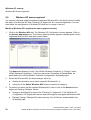
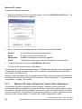
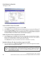
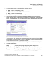
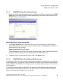
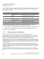
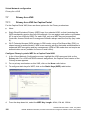
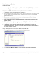
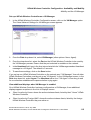
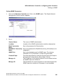
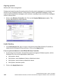
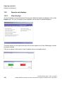
7.
In the left-hand list, click on the IP Addresses option. The Management Port Settings area
(top portion of the screen) displays the factory settings for the HiPath Wireless Controller.
8.
To modify Management Port Settings, click the Modify button. The System Port
Configuration screen appears.
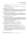
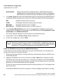
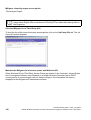
9.
Key in:
Hostname
The name of the HiPath Wireless Controller
Domain
The IP domain name of the enterprise network
Management IP Address
The new IP address for the HiPath Wireless Controller’s
management port (change this as appropriate to the
enterprise network).
A31003-W1010-A100-1-7619, July 2005
HiPath Wireless Controller, Access Points and Convergence Software V3.0: User Guide
27
HWC_Startup.fm
HiPath Wireless Controller: Startup
The graphical user interface (GUI): overview
Subnet mask
For the IP address, the appropriate subnet mask to separate
the network portion from the host portion of the address
(typically 255.255.255.0)
Management Gateway
The default gateway of the network.
Primary DNS
The primary name server used by the network.
Secondary DNS
The secondary name server used by the network
10. Click OK to return to the HiPath Wireless Controller Configuration screen.
11. Click on the Save button to save the port changes.
The web connection between the laptop and the HiPath Wireless Controller is now lost,
because their IP addresses are now on different networks.
3.2.1.2
Adding the HiPath Wireless Controller to your enterprise network
1.
Disconnect the laptop from the HiPath Wireless Controller Management Port.
2.
Connect the HiPath Wireless Controller Management Port to the enterprise ethernet LAN.
The HiPath Wireless Controller resets automatically. Now you will be able to launch the
Controller, Access Points and Convergence Software GUI again, with the system visible to the
enterprise network.
The remaining steps in initial configuration of the Controller, Access Points and Convergence
Software system are described in the next topic, after an overview of the GUI.
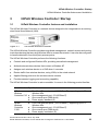
3.3
The graphical user interface (GUI): overview
The administrator can configure and administer the Controller, Access Points and Convergence
Software system using the web-based Graphical User Interface.
To run the graphical user interface
1.
Launch Microsoft Internet Explorer (version 6.0 or above), or other web browser.
2.
In the address bar, key in the URL https://x.x.x.x:5825 (your management gateway as
defined in initial setup plus port 5825, formerly factory default 192.168.10.1:5825). The
Controller, Access Points and Convergence Software login screen appears.
3.
Key in the factory default User Name (”admin”) and Password (“abc123”). Click on the
Login button. The main menu screen appears
>
28
You can define which user names have full read/write access to the user
interface (“Admin” users) and which users have “read-only” privileges. This is
done the HiPath Wireless Controller Configuration: Management Users screen.
A31003-W1010-A100-1-7619, July 2005
HiPath Wireless Controller, Access Points and Convergence Software V3.0: User Guide
HWC_Startup.fm
HiPath Wireless Controller: Startup
The graphical user interface (GUI): overview
The main areas in the Controller, Access Points and Convergence Software user interface are
accessed from the main menu, or by clicking on the appropriate tab across the top of each
screen. Within each area, to access the associated subscreens, click on the screen name in
the left-hand list.
Tab
Screen
Function
Logs & Traces
Logs normal events and alarm events
Trace logs are by component.
Reports & Displays
Access to various on-screen reports
HiPath Wireless
Controller
Configuration
Check Point
Mitigator
VN Manager
SNMP
Network Time
Management Users
Software Maintenance
Tasks including shutdown, enable syslog.
Define static routes, configure OSPF.
Set up management port (Modify screen)
Set up the data ports.
Enable event logging for Check Point.
Enable “detect rogue APs” mechanism.
Manage multiple Controllers.
Enable SNMP messages to be sent.
Configure synchronized time.
Define user level.<
Product Keys and software upgrades.
Wireless AP
Configuration
Highlight a AP
Access Approval
AP Maintenance
AP Registration
Client Disassociate
Modify properties, radios, static config.
Modify the status of a Wireless AP.
View and set up AP software upgrade.
Define registration mode, pairing of APs.
Force a wireless device to disassociate.
Virtual Network
Configuration
Global Settings
Add a subnet
VNS Topology
VNS Authen & Acct
VNS RADIUS Policy
VNS Filtering
VNS Privacy
Define RADIUS servers,& global settings
Left-hand list. Enter name. Click to add.
Define the VNS topology, authentication
and accounting set up
Define Filter IDs
Define filtering rules to control access
Set up WEP keys or WPA privacy.
Mitigator
Table 3-1
System Maintenance
Routing Protocols
IP Addresses
Configure and view reports for the Mitigator
(rogue access point detection)
Controller, Access Points and Convergence Software user interface summary
A31003-W1010-A100-1-7619, July 2005
HiPath Wireless Controller, Access Points and Convergence Software V3.0: User Guide
29
HWC_Startup.fm
HiPath Wireless Controller: Startup
The graphical user interface (GUI): overview
30
A31003-W1010-A100-1-7619, July 2005
HiPath Wireless Controller, Access Points and Convergence Software V3.0: User Guide
HWC_SoftwareConfig.fm
Controller, Access Points and Convergence Software configuration
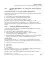
Configuration steps: overview
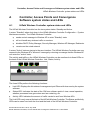
4
Controller, Access Points and Convergence
Software configuration
4.1
Configuration steps: overview
To set up and configure the HiPath Wireless Controller and Wireless APs, follow these steps:
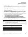
1.
First-time Setup: Perform “First-Time Setup” of the HiPath Wireless Controller on the
physical network to modify the Management Port IP address for the enterprise network.
2.
Product Key: Apply a Product Key file, for licensing purposes. If no Product Key is enabled,
the HiPath Wireless Controller functions with all features enabled in demonstration mode.
3.
Data Port Setup: Set up the HiPath Wireless Controller on the network by configuring the
physical data ports and their function as “host port”, “router port”, or “3rd party AP port”.
4.
Routing Setup: For any port defined as a “router port”, configure static routes and OSPF
parameters, if appropriate to the network
5.
Wireless AP Initial Setup: Connect the Wireless APs to the HiPath Wireless Controller.
They will automatically begin the “Discovery” of the HiPath Wireless Controller, based on
factors that include:
●
their Registration mode (in the Wireless AP Registration screen)
●
the enterprise network services that will support the discovery process.
6.
Wireless AP Configuration: Modify properties or settings of the Wireless AP, if desired.
7.
Virtual Network Services (VNS) Setup: Set up one or more virtual subnetworks on the
HiPath Wireless Controller. For each VNS, configure the following:
●
Topology: configure the VNS, and assign the Wireless APs radios to the VNS.
●
Authentication and Accounting: configure the authentication method for the
wireless device user and enable the accounting method.
●
RADIUS Policy: define Filter ID values for user groups
●
Filtering: define filtering rules to control network access
●
Multicast: define groups of IP addresses for multicast traffic
●
Privacy: select and configure the wireless security method on the VNS.
A31003-W1010-A100-1-7619, July 2005
HiPath Wireless Controller, Access Points and Convergence Software V3.0: User Guide
31
HWC_SoftwareConfig.fm
Controller, Access Points and Convergence Software configuration
Enabling the product key
4.2
Enabling the product key
Once the “First-Time Setup” is complete, the next step in the initial setup of the HiPath Wireless
Controller is to enter your product key. This is a one-time event. The Product Key file is provided
with your HiPath Wireless Controller in a downloaded file.
For assistance, if you cannot find the product key, contact your local represenative. To find your
nearest service organization, access the Siemens website at www.siemens.com, and then
select your country’s Siemens website from the drop-down list. The service organizations for
your country will be listed on the local site. This product area is IP Convergence Solutions or
Wireless.
If no Product Key is enabled, the HiPath Wireless Controller functions with all features enabled
in demonstration mode.
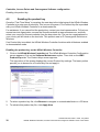
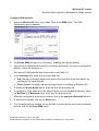
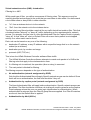
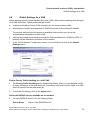
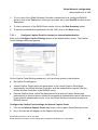
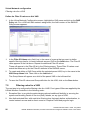
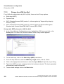
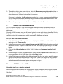
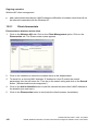
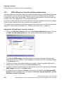
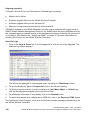
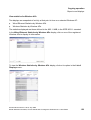
Enabling the product key on the HiPath Wireless Controller
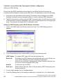
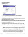
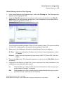
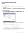
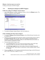
1.
Click on the HiPath Wireless Controller tab. The HiPath Wireless Controller Configuration
screen appears. Click on the Software Maintenance option. Then click on the HWC
Product Keys tab. The Product Keys screen appears.
The top portion of the screen displays the current Product Key settings. The lower portion
permits you to browse for a Product Key file and apply it.
2.
To select a product key file, click Browse to navigate to a downloads folder or a CD drive.
3.
To activate this product key file, click Apply Now.
32
A31003-W1010-A100-1-7619, July 2005
HiPath Wireless Controller, Access Points and Convergence Software V3.0: User Guide
HWC_SoftwareConfig.fm
Controller, Access Points and Convergence Software configuration
Setting up the data ports
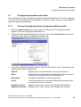
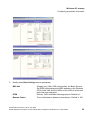
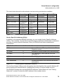
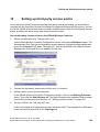
4.3
Setting up the data ports
The next step in the initial setup of the HiPath Wireless Controller is to configure the physical
data ports.
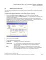
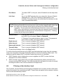
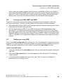
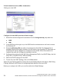
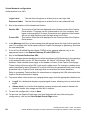
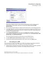
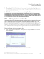
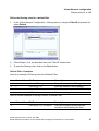
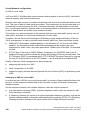
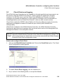
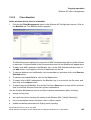
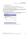
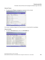
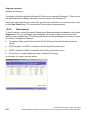
Configuring the data port interfaces on the HiPath Wireless Controller
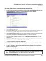
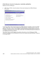
1.
Click on the HiPath Wireless Controller tab. In the HiPath Wireless Controller
Configuration screen, click on the IP Address option. The Management Port Settings and
Interfaces screen appears.
The lower portion of the HiPath Wireless Controller Configuration screen displays the
Interfaces, either the four ethernet ports (for the C10 and C100), or the two ports (for the
C1000). For each port, the MAC address is displayed automatically.
2.
Click in a port row to highlight it.
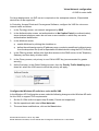
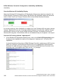
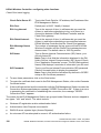
3.
For the highlighted port, key in the:
IP address
IP Address of the physical ethernet port.
Subnet mask
For the IP address, the appropriate subnet mask to separate the
network portion from the host portion of the address (typically
255.255.255.0)
MTU
Maximum Transmission Unit (maximum packet size for this port).
Default setting is 1500. If you change this setting, and are using OSPF,
be sure that the MTU of each port in the OSPF link matches.
A31003-W1010-A100-1-7619, July 2005
HiPath Wireless Controller, Access Points and Convergence Software V3.0: User Guide
33
HWC_SoftwareConfig.fm
Controller, Access Points and Convergence Software configuration
Setting up the data ports
>
4.
In a “Branch Office” scenario, where the Wireless AP is configured statically on
a local network whose MTU is lower than 1500, the HiPath Wireless Controller
automatically adjusts the MTU size to prevent packet fragmentation.
For the highlighted port, select its Function from the drop-down list: Host Port, 3rd Party
AP, Router (defined below).
For OSPF routing on a port, that port must be configured as a “Router” Port. No more than
one port should be configured as a router port.
5.
To allow Management traffic on a highlighted port, click the Mgmt checkbox on. This choice
must be used carefully since it overrides the built-in protection filters on the port.
6.
For the highlighted port, click the SLP checkbox on to allow SLP protocol on this port for
Wireless APs using this port for discovery and registration.
7.
To save the port configuration, click Save.
To cancel the entries without saving, click Cancel.
Port Type or Function
A new HiPath Wireless Controller is shipped from the factory with all its data ports set up as
“Host ports’, and support of management traffic disabled on all data ports. In the HiPath
Wireless Controller Configuration – IP Addresses screen, you can redefine the data ports to
function as one of three types:
●
Host Port
Use ”Host Port” for connecting Wireless APs, with no dynamic routing. A “Host Port” has
dynamic routing disabled to ensure that the port does not participate in dynamic routing
operations, such as OSPF, to advertise the availability of Virtual Network Segments (VNS)
hosted by the HiPath Wireless Controller. “Host Ports” may still be used as the target for
static route definitions.
●
Third-Party AP Port
Define as “3rd-Party AP” a port to which you will connect third-party access points. No
more than one port can be configured for third-party APs.
Selecting this option prepares the port to support a third-party AP setup that allows the
mapping of a VNS to the physical port. The VNS settings then permit the definition of policy,
such as filters and Captive Portal, that manage the traffic flow for wireless users connected
to these access points.
The third-party access points must be operating as layer-2 bridges. The “third-party AP”
VNS is isolated from the rest of the network. The HiPath Wireless Controller assumes
control over the layer-3 functions such as DHCP.
34
A31003-W1010-A100-1-7619, July 2005
HiPath Wireless Controller, Access Points and Convergence Software V3.0: User Guide
HWC_SoftwareConfig.fm
Controller, Access Points and Convergence Software configuration
Setting up static routes
Wireless APs must not be attached to a “3rd-Party AP” port.
●
Router Port
Define as “Router Port” a port that you wish to connect to an upstream next-hop router in
the network. Dynamic routing protocol such as OSPF can be turned on for this port type.
Wireless APs can be attached to a “Router” port. The HiPath Wireless Controller will create
a virtual VNS port and handle wireless device traffic in the same manner as a “Host port”.
Third-party access points must not be directly connected to a “Router” port.
There is a fourth port type that is not configurable in the user interface:
●
Virtual Network Services (VNS) interface
A VNS port is a virtual port created automatically on the HiPath Wireless Controller when
a new VNS is defined. The VNS port becomes the default gateway for wireless devices on
this VNS. No Wireless APs can be associated with a VNS port and no routing is permitted
on this port.
The chart below summarizes the port types and their functions:
Port Type
IP Forwarding
Wireless AP Mgmt traffic support
Routing protosupport
(SNMP, HTTP, TELNET, col support (IP,
SLP, RADIUS, DHCP) OSPF and PIM)
Host
No
Yes
Selectable
No
No
Selectable
No
3rd-Party AP No
Router
Selectable. Route Yes
wireless device
traffic only
Selectable
Selectable
VNS
No
Selectable
No
Table 4-1
Port types and functions
4.4
No
Setting up static routes
It is recommended that you define a default route to your enterprise network, either with a static
route or by using OSPF protocol. This will enable the HiPath Wireless Controller to forward
wireless packets to the remainder of the network.
A31003-W1010-A100-1-7619, July 2005
HiPath Wireless Controller, Access Points and Convergence Software V3.0: User Guide
35
HWC_SoftwareConfig.fm
Controller, Access Points and Convergence Software configuration
Setting up static routes
Setting up a static route on the HiPath Wireless Controller
1.
Click on the HiPath Wireless Controller tab. In the HiPath Wireless Controller
Configuration screen, click on the Routing Protocols option.
2.
Click the Static Routes tab. The Static Routes screen appears.
3.
To add a new route, click in the Destination Address field and key in the destination IP
address of a packet.
[The destination network IP address that this static route applies to. Packets with this
destination address will be sent to the Destination below.]
To define a default static route for any unknown address not in the routing table, key in
0.0.0.0.
4.
Key in the Subnet Mask. For the IP address, the appropriate subnet mask to separate the
network portion from the host portion of the address (typically 255.255.255.0).
For the default static route for any unknown address, key in 0.0.0.0.
5.
In the Gateway field, key in the IP address of the gateway (the IP address of the specific
router port or gateway on the same subnet as the HiPath Wireless Controller to which to
route these packets; that is, the IP address of the next hop between the HiPath Wireless
Controller and the packet’s ultimate destination).
6.
Click on the Add button. The new route appears in the list, numbered sequentially.
36
A31003-W1010-A100-1-7619, July 2005
HiPath Wireless Controller, Access Points and Convergence Software V3.0: User Guide
HWC_SoftwareConfig.fm
Controller, Access Points and Convergence Software configuration
Setting up OSPF Routing
7.
The Override dynamic routes checkbox is on by default. This means the static routes
defined here will have priority over the OSPF learned routes (including default route) that
the HiPath Wireless Controller uses for routing. If you wish to remove this priority for static
routes, so that routing is controlled dynamically at all times, click the Override dynamic
routes checkbox off.
>
8.
If you enable dynamic routing (OSPF), the dynamic routes will normally have
priority for outgoing routing. For internal routing on the HiPath Wireless
Controller, the static routes normally have priority.
Click on Save to update the routing table on the HiPath Wireless Controller.
Viewing the Routing Table on the HiPath Wireless Controller
To view the static routes that have been defined for the HiPath Wireless Controller, click on the
View Forwarding Table tab. This displays the Forwarding Table also accessed in the Reports
& Displays area of the user interface.
This report displays all defined routes, whether static or OSPF, and their current status. To
update the display, click on the Refresh button.
4.5
Setting up OSPF Routing
To enable OSPF routing, you must first define one data port as a “Router Port” in the IP
Addresses screen. Next, enable OSPF globally on the HiPath Wireless Controller, and define
the global OSPF parameters. Then you enable (or disable) OSPF on the port that you defined
as a “Router Port”.
A31003-W1010-A100-1-7619, July 2005
HiPath Wireless Controller, Access Points and Convergence Software V3.0: User Guide
37
HWC_SoftwareConfig.fm
Controller, Access Points and Convergence Software configuration
Setting up OSPF Routing
Ensure that the OSPF parameters defined here for the HiPath Wireless Controller are
consistent with the adjacent routers in the OSPF area. The parameters include the following:
●
If the peer router has different timer settings, the protocol timer settings in the HiPath
Wireless Controller must be changed to match, in order to achieve OSPF adjacency.
●
The MTU of the ports on either end of an OSPF link must match. The MTU for ports on the
HiPath Wireless Controller is defined as 1500, in the IP Addresses screen, during data port
setup. This matches the default MTU in standard routers.
Setting up OSPF Routing on the HiPath Wireless Controller
1.
Click on the OSPF tab in the Routing Protocols screen. The OSPF Settings screen
appears.
2.
In the Global Settings area, enable OSPF by filling in the following fields:
OSPF Status: To enable OSPF, select ON from the drop-down list.
Router ID:
If left blank, the OSPF daemon will automatically pick a router ID from one
of the HiPath Wireless Controller’s interface IP addresses.
If filled in here with the IP address of the HiPath Wireless Controller, this
ID must be unique across the OSPF area.
Area ID:
0 is the main area in OSPF
Area Type:
Select Default (Normal), Stub, or Not-so-stubby (OSPF area types) from
the drop-down list.
3.
To save these settings, click on the Save button.
4.
In the Port Settings area, for the data port defined as a “Router Port”, fill in these fields:
38
A31003-W1010-A100-1-7619, July 2005
HiPath Wireless Controller, Access Points and Convergence Software V3.0: User Guide
HWC_SoftwareConfig.fm
Controller, Access Points and Convergence Software configuration
Filtering at the interface level
Port Status:
To enable OSPF on the port, select Enabled from the drop-down
list.
Link Cost:
Key in the OSPF standard for your network for this port. Default
displayed is 10. (The cost of sending a data packet on the
interface. The lower the cost, the more likely the interface is to be
used to forward data traffic.)
>
If more than one port is enabled for OSPF, it is desirable to prevent the HiPath
Wireless Controller from serving as a router for other network traffic (other than
the traffic from wireless device users controlled by the HiPath Wireless
Controller). To ensure that the HiPath Wireless Controller is never the preferred
OSPF route, one solution is to set the Link Cost to its maximum value of 65535.
Filters should also be defined in the Virtual Network Configuration – Filtering
screen that will drop routed packets.
Authentication:
From the drop-down list, select the authentication type set up for
the OSPF on your network: None or Password.
Password:
If “Password” was selected above, key it in here. This password
must match on either end of the OSPF connection.
Dead-Interval:
Time in seconds (displays OSPF default).
Hello-Interval:
Time in seconds (displays OSPF default).
Retransmit-Interval: Time in seconds (displays OSPF default).
Transmit delay:
5.
Time in seconds (displays OSPF default).
To save these settings, click on the Save button.
To confirm that the ports are set up for OSPF, and that advertised routes from the upstream
router are recognized, click View Forwarding Table to view the Forwarding Table report. Two
additional reports display OSPF information when the protocol is in operation:
●
OSPF Neighbor report displays the current neighbors for OSPF (routers that have
interfaces to a common network)
●
OSPF Linkstate report shows the Link State Advertisements (LSAs) received by the
currently running OSPF process. The LSAs describe the local state of a router or network,
including the state of the router’s interfaces and adjacencies.
4.6
Filtering at the interface level
The Controller, Access Points and Convergence Software has a number of built-in filters that
protect the system from unauthorized traffic. These filters are applied at the network interface
level and are automatically invoked.
A31003-W1010-A100-1-7619, July 2005
HiPath Wireless Controller, Access Points and Convergence Software V3.0: User Guide
39
HWC_SoftwareConfig.fm
Controller, Access Points and Convergence Software configuration
Filtering at the interface level
In addition to these built-in filters, the administrator can define specific exception filters at the
interface-level to customize network access. These filters do not depend on a VNS definition.
4.6.1
Port-based exception filters: built-in
On the HiPath Wireless Controller, various port-based exception filters are built in and invoked
automatically. These filters protect the HiPath Wireless Controller from unauthorized access to
system management functions and services via the ports.
For example, on the HiPath Wireless Controller’s data interfaces (both physical interfaces and
VNS virtual interfaces), the built-in exception filter prohibits invoking SSH, HTTPS, or SNMP.
However, such traffic is allowed, by default, on the Management port.
To enable SSH, HTTPS, or SNMP access through a data interface, select the interface in the
IP Addresses screen and click the "Management" checkbox on. You can also enable such
management traffic in the VNS definition.
If management traffic is explicitly enabled for any interface (physical port or VNS), access is
implicitly extended to that interface through any of the other interface. (VNS).
Only traffic specifically allowed by the interface’s exception filter is allowed to reach the HiPath
Wireless Controller itself. All other traffic is dropped. Exception filters are dynamically
configured, and are regenerated whenever the system's interface topology changes (a change
of IP address for any interface).
Enabling management traffic on an interface adds additional rules to the exception filter to open
up the well-known IP(TCP/UDP) ports corresponding to the HTTPS, SSH and SNMP
applications.
The port-based built-in exception filtering rules, in the case of traffic from VNS users, operate
only on traffic that is targeted directly to one of the VNS's interfaces. For example, a VNS filter
may be generic enough to allow traffic access to the HiPath Wireless Controller's management
(Allow All [*.*.*.*]). The traffic will initially be allowed according to the VNS user’s policy, but may
then be denied by the exception filter of the VNS interface.
4.6.2
Port-based exception filters: user defined
You can add specific filtering rules at the port level in addition to the built-in rules. Such rules
give you the capability of restricting access to a port, for specific reasons, such as a Denial of
Service (DoS) attack.
To define filtering rules that are associated with one of the physical data ports on the HiPath
Wireless Controller rather than with a VNS, use the Port Exception Filter screen.
The filtering rules are set up in the same manner as filtering rules defined for a VNS — specify
an IP address and then either “Allow” or “Deny” traffic to that address. See Section 7.5,
“Filtering rules for a VNS”, on page 90.
40
A31003-W1010-A100-1-7619, July 2005
HiPath Wireless Controller, Access Points and Convergence Software V3.0: User Guide
HWC_SoftwareConfig.fm
Controller, Access Points and Convergence Software configuration
Filtering at the interface level
Exception filtering rules that you will define for a VNS will apply to the wireless device users
after their authentication, whereas the filtering rules that you define here apply to all traffic on
a physical port.
Define port exception filters
1.
Click on the HiPath Wireless Controller tab. Click on the Port Exception Filters option.
The Port Exception Filters screen appears.
2.
Select the data port from the pull-down list to which these filters will apply.
3.
For each filtering rule you are defining:
IP / Port:
Type in the destination IP address. You can also specify an IP range, a port
designation or a port range on that IP address.
Protocol:
Default is N/A. To specify a protocol, select from the drop-down list (may
include UDP, TCP, IPsec-ESP, IPsec-AH, ICMP).
4.
Click on the Add button. The information appears in a new line in the Filter area of the
screen.
5.
Highlight the new filtering rule and click Allow checkbox on to allow traffic. Leave
unchecked to disallow traffic.
6.
Edit the order of a filtering rule by highlighting the line and clicking on the Up and Down
buttons. The filtering rules are executed in the order defined here.
7.
To save the filtering rules, click on the Save button.
A31003-W1010-A100-1-7619, July 2005
HiPath Wireless Controller, Access Points and Convergence Software V3.0: User Guide
41
HWC_SoftwareConfig.fm
Controller, Access Points and Convergence Software configuration
Filtering at the interface level
42
A31003-W1010-A100-1-7619, July 2005
HiPath Wireless Controller, Access Points and Convergence Software V3.0: User Guide
HWC_APStartup.fm
Wireless AP: startup
Wireless AP features
5
Wireless AP: startup
You are now ready to add the Wireless APs to the Controller, Access Points and Convergence
Software system and register them with the HiPath Wireless Controller. Before the Wireless
APs can handle wireless traffic, you will also need to assign the Wireless APs to a VNS.
5.1
Wireless AP features
The Wireless AP is a wireless LAN access point using the 802.11 wireless standards (802.11a,
802.11b and 802.11g) for network communications. The Wireless AP bridges network traffic to
an Ethernet LAN.
The Wireless AP is provided with proprietary software that allows it to communicate only with
the HiPath Wireless Controller.
The Wireless AP is physically connected to a LAN infrastructure and establishes an IP
connection to a HiPath Wireless Controller. The Wireless AP has no user interface. The only
way to manage a Wireless AP is through the HiPath Wireless Controller.
All communication with the HiPath Wireless Controller is carried out using a UDP-based
protocol to encapsulate IP traffic from the Wireless APs and direct it to the HiPath Wireless
Controller. The HiPath Wireless Controller decapsulates the packets and routes them to the
appropriate destinations, while managing sessions and applying policy.
Figure 5-1
The Wireless AP
The Wireless AP has two radios:
●
a 5 GHz radio that supports the 802.11a standard
The 802.11a standard is an extension to 802.11 that applies to wireless LANs and provides
up to 54 Mbps in the 5-GHz band. 802.11a uses an orthogonal frequency division
multiplexing encoding scheme rather than FHSS or DSSS.
●
a 2.4 GHz radio that supports both the 802.11g and 802.11b standards
A31003-W1010-A100-1-7619, July 2005
HiPath Wireless Controller, Access Points and Convergence Software V3.0: User Guide
43
HWC_APStartup.fm
Wireless AP: startup
Installing the Wireless APs
The 802.11g standard applies to wireless LANs and specifies a transmission rate of 54
Mbps. The 802.11b (High Rate) standard is an extension to 802.11 that specifies a
transmission rate of 11 Mbps. Because 802.11g uses the same communication frequency
range as 802.11b (2.4 GHz), 802.11g devices can co-exist with 802.11b devices on the
same network
Either radio on the Wireless AP can be enabled or disabled in the user interface. Both radios
can be enabled and offer service simultaneously.
The Wireless AP supports the full range of 802.11a:
5.15 to 5.25 GHz
U-NII Low Band
5.25 to 5.35 GHz
U-NII Middle Band
5.725 to 5.825 GHz
U-NII High Band
New 5.470 GHz to 5.725 GHz Band
(when approved by FCC)
The U-NII bands (Unlicensed National Information Infrastructure) are three frequency bands of
100 MHz each in the 5 GHz band designated for short-range, high-speed wireless networking
communication.
Wireless APs are licensed to operate in North America, the European Union countries and
European Union free trade countries. The Wireless AP will operate on the radio band allowed
for each European Union country, after being configured on the HiPath Wireless Controller in
the Wireless AP Configuration: Properties screen.
The Wireless AP has two models:
●
internal antenna (Model AP2610), internal dual (multimode) diversity antennas
●
external antenna (Model AP2620) (dual external antennas), RP-SMA connectors
For North America, the U-NII Low Band (5.15 to 5.25 GHz band) is disabled for the Model
AP2620 to comply with FCC regulations.
5.2
Installing the Wireless APs
Install the Wireless APs as described in the AP Install Guide packed with the units.
1.
Unpack the Wireless AP from its shipment carton. Check that all parts are present, using
the AP Install Guide packed with the unit.
2.
Mount the Wireless AP wall bracket, using 3 screws, near the LAN ethernet cable plug
coming from the wall.
44
A31003-W1010-A100-1-7619, July 2005
HiPath Wireless Controller, Access Points and Convergence Software V3.0: User Guide
HWC_APStartup.fm
Wireless AP: startup
Connecting and powering the Wireless AP
3.
Press the back of the Wireless AP onto the bracket, aligning it with the open notches in the
bracket. Then slide it downwards until it clicks into place.
To remove the Wireless AP, release the spring clip by inserting the Allen key (provided) into
the small hole at the bottom of the bracket. Use the Allen key to depress the spring clip.
Then slide the case up the bracket and lift off the Wireless AP. Keep the Allen key in a safe
place.
4.
Insert the plastic spreading rivet through the hole at the bottom of the bracket and into the
Wireless AP case. Then screw in the plastic screw. This spreads the rivet and locks the
case to the bracket. To remove the Wireless AP, use a screwdriver to take out the screw.
7
5.3
7
For installations that use Receive diversity (the default) the antennae should be
pointed in the same direction. For installations that do NOT use Receive diversity or
for those that split the 802.11a and 802.11b/g radio onto different physical ports,
then the antennae can be pointed in whatever direction is desired.
Connecting and powering the Wireless AP
This device must not be connected to a LAN segment with outdoor wiring.
Ensure that all cables are run correctly to avoid strain. Replace the power supply
adapter immediately, if it shows any signs of damage.
A31003-W1010-A100-1-7619, July 2005
HiPath Wireless Controller, Access Points and Convergence Software V3.0: User Guide
45
HWC_APStartup.fm
Wireless AP: startup
Discovery and registration: Wireless AP registration settings
Powering up the Wireless AP initiates its automatic discovery and registration process with the
HiPath Wireless Controller, The parameters for this process should be set in the Wireless AP
Registration screen.
Connect and power up the Wireless APs in one of three ways:
Power Over Ethernet (PoE)
●
If your network is already set up with PoE, attach the LAN ethernet cable to the RJ45
ethernet connector at the top of the Wireless AP.
Power Over Ethernet: Adding PoE Injector
●
If your network is not set up with PoE, you can provide power to the ethernet cable with a
PoE injector. The PoE injector must be 802.3af compliant. The PoE injector is not provided
with the Wireless AP.
Power by AC Adaptor
●
An AC adaptor is not provided with the Wireless AP. If you wish to use one, the specifications are: Input: 120-240 VAC, Output Voltage DC +6V, max amps 1.50, max watts 10.
To use an adaptor, install the Wireless AP within six feet of a wall outlet, attach the adaptor to
the Wireless AP and then plug the adaptor into the wall outlet.
7
5.4
Use only a safety approved POE injector or a safety approved Limited Power Source
(Class 2) AC adaptor. Do not connect both power sources at the same time.
Discovery and registration: Wireless AP registration settings
Before the Wireless APs are powered and begin their “discovery” process, you should define
the parameters of this process in the Wireless AP Registration screen. In this screen, you
define two elements involved in the “discovery” process:
●
Security Mode
●
Discovery Timers
The Stand-alone or Paired options are part of the Availability feature to define a failover HiPath
Wireless Controller if the primary HiPath Wireless Controller fails, described later in this Guide.
During the “Registration” process, the HiPath Wireless Controller’s approval of the serial
number of the Wireless AP depends on the security mode that has been set:
●
46
Allow all
If the HiPath Wireless Controller does not recognize the serial number, it sends a default
configuration to the Wireless AP.
If it recognizes the serial number, it sends the specific configuration (port and binding key)
set for that Wireless AP.
A31003-W1010-A100-1-7619, July 2005
HiPath Wireless Controller, Access Points and Convergence Software V3.0: User Guide
HWC_APStartup.fm
Wireless AP: startup
Discovery and registration: Wireless AP registration settings
●
Allow approved
If the HiPath Wireless Controller does not recognize the serial number, the operator is
prompted to create a configuration.
If it recognizes the serial number, it sends the configuration for that Wireless AP.
>
It may be advisable, for the initial set up of the network, to select the "Allow All"
option here. This is the most efficient way to get a large number of Wireless APs
registered with the HiPath Wireless Controller.
After that, you may want to reset this option to "Allow Approved", so that no
unapproved Wireless APs would be able to connect. You can modify the status
of an unapproved Wireless AP in the Access Approval screen.
Define the Security Mode for registering Wireless APs
1.
Select the Wireless APs tab in any screen. Click on AP Registration. The Wireless AP
Registration Mode screen appears.
2.
To allow all Wireless APs to connect, click this radio button (default mode)
To allow only approved Wireless APs to connect, click on this radio button.
Set the discovery timers
3.
Define the timing parameters for the "discovery" process:
Number of Retries
The default number of retries is 3.
Delay between Retries
4.
The default is 1 second
To save the above parameters, click the Save button.
A31003-W1010-A100-1-7619, July 2005
HiPath Wireless Controller, Access Points and Convergence Software V3.0: User Guide
47
HWC_APStartup.fm
Wireless AP: startup
Discovery and registration
This completes the preparation for the "discovery" process. Now you can go back to the
Wireless APs and power them on.
5.5
Discovery and registration
When the Wireless AP is powered on, it automatically begins a "discovery" process to
determine the IP address of the HiPath Wireless Controller. When successful, it registers with
the HiPath Wireless Controller.
When the Wireless AP is registered, it appears in the Wireless AP Access Approval screen.
You can check its status in this screen. If the status is “Pending”, you must modify it to
“Approved”.
You can now assign the registered and approved Wireless AP to a Virtual Network Segment
(VNS) and it will be ready to handle wireless traffic.
5.5.1
Discovery steps
The Wireless APs "discover" the IP address of a HiPath Wireless Controller using a sequence
of mechanisms that allow for the possible services available on the enterprise network.
The "discovery" steps are processed in the following order, until the Wireless AP successfully
locates a HiPath Wireless Controller with which it can "register".
1.
Use the IP address of the last successful connection to a HiPath Wireless Controller.
2.
Use the predefined static IP addresses for the HiPath Wireless Controllers on the network
(if so configured).
3.
Use Dynamic Host Configuration Protocol (DHCP) Option 78 to locate a Service Location
Protocol (SLP) Directory Agent (DA), followed by a unicast SLP request to the Directory
Agent.
4.
Use a Domain Name Server (DNS) lookup for the host name "Controller.domain-name".
5.
Use a multicast SLP request to find SLP Service Agents (SAs).
You must ensure that the appropriate services on your enterprise network are prepared to
support the "discovery" process.
Discovery step 1: last successful connection
Once a Wireless AP has successfully registered with a HiPath Wireless Controller, it
remembers that controller's IP address, and will use that address on subsequent reboots. In
effect, it will bypass discovery, and go straight on to registration. However, if this discovery
method fails, it cycles through the remaining steps until it meets with success.
48
A31003-W1010-A100-1-7619, July 2005
HiPath Wireless Controller, Access Points and Convergence Software V3.0: User Guide
HWC_APStartup.fm
Wireless AP: startup
Discovery and registration
Discover step 2: static IP address
You can specify a list of static IP addresses of the HiPath Wireless Controllers on your network.
On the Wireless AP Configuration screen "Static Configuration" tab, add the addresses to the
"Wireless Controller Search List".
7
Care must be taken when setting or changing these values. Wireless APs configured
statically will connect only to HiPath Wireless Controllers in the list. Improperly
configured Wireless APs will not be able to connect to a non-existent HiPath
Wireless Controller address and therefore will not be able to receive a corrected
configuration.
Discovery step 3: the DHCP and unicast SLP solution
To use the DHCP and unicast SLP discovery method, you must ensure that the DHCP server
on your network supports Option 78 (DHCP for SLP RFC2610). The Wireless APs use this to
discover the HiPath Wireless Controller.
This solution takes advantage of two services that are present on most networks:
●
DHCP (Dynamic Host Configuration Protocol), the standard means of providing IP
addresses dynamically to devices on a network.
●
SLP (Service Location Protocol), a means of allowing client applications to discover
network services without knowing their location beforehand. Devices advertise their
services, using a Service Agent. In larger installations, a Directory Agent collects
information from Service Agents and creates a central repository (SLP RFC2608).
The HiPath Wireless Controller contains an SLP Service Agent that, when it starts up, queries
the DHCP server for Option 78 and if found, registers itself with the Directory Agent as service
type "siemens". The HiPath Wireless Controller contains a Directory Agent (slpd).
The Wireless AP queries DHCP servers for Option 78 in order to locate any Directory Agents.
The Wireless AP's SLP User Agent will then query the DAs for a list of "siemens" Service
Agents.
Option 78 needs to be set for the subnets connected to the ports of the HiPath Wireless
Controller and the subnets connected to the Wireless APs. These should contain an identical
list of Directory Agent IP addresses.
Discovery step 4: the DNS solution
If no Directory Agent is found, or if it has no "siemens" Service Agents registered, the Wireless
AP will attempt to locate a HiPath Wireless Controller via DNS.
If you choose to use this method for discovery, place an "A" record in the DNS server for
"Controller.<domain-name>". The <domain-name> is optional, but if you use one, ensure that
it is listed with the DHCP server.
A31003-W1010-A100-1-7619, July 2005
HiPath Wireless Controller, Access Points and Convergence Software V3.0: User Guide
49
HWC_APStartup.fm
Wireless AP: startup
Discovery and registration
Discovery step 5: the multicast SLP solution
If all of the preceding methods fail to locate a HiPath Wireless Controller, then the Wireless AP
sends out a multicast SLP request, looking for any SLP Service Agents providing the "siemens"
service.
Registration after discovery
Any of the discovery steps 2 through 5 can inform the Wireless AP of a list of multiple IP
addresses to which the Wireless AP may attempt to connect. Once the Wireless AP has
"discovered" these addresses, it sends out connection requests to all of them simultaneously.
It will attempt to register only with the first which responds to its request.
When the Wireless AP obtains the IP address of the HiPath Wireless Controller, it connects and
registers, sending its serial number identifier to the HiPath Wireless Controller, and receiving
from the HiPath Wireless Controller a port IP address and binding key.
Once a Wireless AP is registered with a HiPath Wireless Controller:
●
it appears in the Wireless AP Access Approval screen. You can check its status in this
screen. If the registration mode was “Approved only” then the status will be “Pending”. You
must modify it to “Approved”.
●
it appears in the side list in the Wireless AP Configuration: Properties screen, where you
can modify the properties and radio parameters.
●
its two radios appear as available choices in the Virtual Network Configuration: Topology
screen, when you are setting up a VNS (up to four VNSs for each radio).
Before a registered Wireless AP can handle wireless traffic, you must set up a VNS definition
and assign the Wireless AP's radios to a VNS. See Section 7, “Virtual Network configuration”,
on page 73.
Discovery and registration: Wireless AP LED sequence
As the Wireless AP is powered on and boots up, you can follow its progress through the
registration process by observing the LED sequence described below.
The Status LED (center) also indicates power: dark when unit is off and green (solid) when the
AP has completed discovery and is operational.
The Wireless AP boot sequence is described below:
50
A31003-W1010-A100-1-7619, July 2005
HiPath Wireless Controller, Access Points and Convergence Software V3.0: User Guide
HWC_APStartup.fm
Wireless AP: startup
Discovery and registration
1.
When powered on, the Wireless AP status LED turns from dark to green briefly.
Status LED: green (solid) then to dark before beginning boot sequence.
2.
The Wireless AP performs a self-test.
Status LED: red (solid) if POST failed.
3.
The "Discovery" mode: the Wireless AP sends a request to the DHCP server on the
enterprise network for the location of the HiPath Wireless Controller (as described above.)
Status LED: orange (solid) while searching ("Discovery")
Status LED: red-orange (alternate blink) if DHCP server not found on network
Status LED: green-orange (alternate blink) if SLP issues in failed discovery.
4.
The Wireless AP "learns" the IP address of the HiPath Wireless Controller,
Status LED: orange (blink) when IP address successfully obtained ("Registration" process
underway)
Status LED: red (blink) if "Registration" fails
5.
The Wireless AP sends its serial number (a unique identifier that is hard coded during
manufacture) to the HiPath Wireless Controller.
Status LED: green (blink) when Wireless AP finds HiPath Wireless Controller ("Standby"
status)
6.
The HiPath Wireless Controller sends the Wireless AP a port IP address and a binding key,
as follows:
●
If the HiPath Wireless Controller does not recognize the serial number, it sends a
default configuration to the Wireless AP.
●
If it does recognize the serial number, it sends the specific configuration (port and
binding key) set for that Wireless AP.
The HiPath Wireless Controller also adds the Wireless AP to its database.
Status LED: green (blink) when Wireless AP finds HiPath Wireless Controller ("Standby"
status)
7.
When the binding key is received, the Wireless AP's status changes from "Standby" to
"Active". It becomes active and is enabled to transmit data traffic.
LED: green steady ("Active")
When the Wireless AP has wireless traffic, you will see a green blink on the traffic LED. The left
LED indicates the traffic LED for activity on the 2.4 GHz radio, while the right LED indicates
activity on the 5 GHz radio.
A31003-W1010-A100-1-7619, July 2005
HiPath Wireless Controller, Access Points and Convergence Software V3.0: User Guide
51
HWC_APStartup.fm
Wireless AP: startup
Wireless AP access approval
5.6
Wireless AP access approval
You can also view and modify the status of registered Wireless APs. Use this function to modify
the status of a Wireless AP from "Pending" to "Approved" for a manual registration. You can
also delete the configuration of Wireless APs that are no longer in service.
Modify a Wireless AP's registration status (approve access)
1.
Click on the Wireless APs tab. The Wireless AP Configuration screen appears. Click on
the Access Approval option. The Access Approval screen appears, displaying the current
registered Wireless APs and their current status.
The Home field displays "Local" (this HiPath Wireless Controller) or "Foreign" (other
HiPath Wireless Controllers), if you have set up two Controllers in Paired Mode, as
described in the HiPath Wireless Controller Configuration: Availability topic.
2.
3.
52
Select the Wireless APs for status change, either by:
●
clicking the checkbox on to select a specific Wireless AP, or
●
using one of the Select Wireless APs buttons to select by category
To perform an action on the selected Wireless APs, click on one of the Action buttons:
Approved, Pending, Release, Delete.
●
Change a Wireless AP's status from "Pending" to "Approved", if the Wireless AP
Configuration: AP Registration screen was set to register only approved Wireless APs.
●
Release "foreign" Wireless APs after recovery from a Failover, as described in the
Availability topic.
A31003-W1010-A100-1-7619, July 2005
HiPath Wireless Controller, Access Points and Convergence Software V3.0: User Guide
HWC_APStartup.fm
Wireless AP: startup
Configuring properties and radios
5.7
Configuring properties and radios
Once a Wireless AP has successfully registered on the HiPath Wireless Controller, it appears
in the side list in the Wireless AP Configuration: Properties screen, where you can modify its
properties and radio parameters.
5.7.1
View and modify properties of registered Wireless APs
1.
Select the Wireless APs tab in any screen. The Wireless AP Configuration screen
appears, with a list of registered Wireless APs.
2.
Highlight the appropriate Wireless AP in the list. Click on the AP Properties tab to view
basic information about the highlighted Wireless AP.
3.
To modify the default information about a selected Wireless AP, key in information in the
following fields (where appropriate):
Serial #
(Display only) A unique identifier set during manufacture.
Name
Defaults to the serial number. Change this to a unique descriptive
name that more easily identifies the Wireless AP.
Description
Available for descriptive comments (optional).
Port #
From the drop-down list, select the ethernet port through which
the Wireless AP can be reached.
Hardware Version
(Display only) Current version of the Wireless AP hardware.
Application Version
(Display only) Current version of the Wireless AP software.
A31003-W1010-A100-1-7619, July 2005
HiPath Wireless Controller, Access Points and Convergence Software V3.0: User Guide
53
HWC_APStartup.fm
Wireless AP: startup
Configuring properties and radios
Status
(Display only) "Approved" = Wireless AP has received its binding
key from the HiPath Wireless Controller after the Discovery
process. "Pending" = binding key not yet received.
You can modify the status of a Wireless AP (for example from
"Pending" to "Approved") in the Access Approval screen.
Active Clients
(Display only) The number of wireless devices currently active on
the Wireless AP.
Poll Timeout
The default is 30 seconds.
Poll Interval
The default is 5 seconds.
4.
If this Wireless AP is to used in Bridge Mode as part of a static configuration for Branch
Office deployment, click the Maintain client session in event of poll failure checkbox on
in order to maintain the session. See Section 5.7.3, “Wireless AP static configuration:
branch office deployment”, on page 58.
5.
To save the modified information, click on the Save button.
5.7.2
View and modify the radio settings of registered Wireless APs
Most properties of the Wireless AP radios can be modified without triggering a reboot of the
Wireless AP. However, modifying the following will trigger a reboot:
●
enabling or disabling either radio
●
changing the radio channel between "Auto" and any fixed channel number.
View and modify the radio settings
1.
Select the Wireless APs tab in any screen. The Wireless AP Configuration screen
appears, with a list of registered Wireless APs.
2.
Highlight the appropriate Wireless AP in the list. Then click on either radio tab:
●
802.11 b/g (2.4 GHz radio)
●
802.11a (5 GHz radio)
Each screen displays the default radio settings for each radio on the Wireless AP. If this
radio has been assigned to a VNS (up to four VNSs), the VNS names and MAC addresses
appear in the Base Settings area.
54
A31003-W1010-A100-1-7619, July 2005
HiPath Wireless Controller, Access Points and Convergence Software V3.0: User Guide
HWC_APStartup.fm
Wireless AP: startup
Configuring properties and radios
3.
Modify these Base Settings where appropriate.
BSS Info
(Display only) After VNS configuration, the Basic Service
Set (BSS) area displays the MAC address on the Wireless
AP for each VNS and the SSIDs of the VNSs to which this
radio has been assigned.
DTIM
Delivery Traffic Indication Message period. Default is 1.
Beacon Period
Time units between beacon transmissions. Default is 100.
A31003-W1010-A100-1-7619, July 2005
HiPath Wireless Controller, Access Points and Convergence Software V3.0: User Guide
55
HWC_APStartup.fm
Wireless AP: startup
Configuring properties and radios
Short Retry Limit
The maximum number of transmission attempts of a frame
that is less than or equal to the RTS Threshold, before a
failure condition is indicated. Default is 200.
Long Retry Limit
The maximum number of transmission attempts of a frame
that is greater than the RTS Threshold, before a failure
condition is indicated. Default is 201.
RTS Threshold
Request To Send Threshold, the size of a data unit below
which an RTS/CTS (RTS/Clear to Send) handshake is not
performed. Default is 2346.
Frag. Threshold
The Fragmentation Threshold, the maximum size of a
packet or data unit that can be delivered. Default is 2346.
Enable Radios
Click checkbox on for each radio.
Radio Settings:
Channel
(Drop-down list) The wireless channel that the Wireless AP
should use to communicate with wireless devices (see
chart below). Depending on the regulatory domain (based
on country), some channels may be restricted. The default
setting is based on North America.
Tx Power Level
(Drop-down list) Min, 13%, 25%, 50%, Max
If DRM was enabled in the previous window, it will override
selections made here in the Tx Power Level field.
Operational Rate Set
(Drop-down list) in Mbps
A: Best data rate, 6, 9 12,18, 24, 36, 48, 54
B/G: Best data rate, 1, 2, 5.5, 11, 6, 9 12,18, 24, 36, 48, 54
Diversity
From the drop-down list, select "Best," for the best signal
from both antennas, or "Left" or "Right" to choose either of
the two diversity antennas.
Basic Rates
(for b radio only) Select a set of basic rates from the dropdown list. The best data rate from the set will be used for
current conditions (power vs. range)
Short Preamble Invoked
Click checkbox on to enable.
g Radio Settings:
56
Protection Mode
(Drop-down list) None, Auto (default), Always
Protection Rate
(Drop-down list) in Mbps: 1, 2, 5.5, 11 (default)
Protection Type
(Drop-down list) CTS (Clear To Send), RTS CTS (Request
To Send, Clear To Send) - default.
A31003-W1010-A100-1-7619, July 2005
HiPath Wireless Controller, Access Points and Convergence Software V3.0: User Guide
HWC_APStartup.fm
Wireless AP: startup
Configuring properties and radios
>
Radio A Channels 100 to 140 occupy the 5470-5725 MHz band, in the
regulatory domains of the European Union and European Union free trade
countries.
Radio B/G Channels 12 to 14 are not available in North America.
Radio Channels
802.11a
Auto
34: 5170 MHz
36: 5180 MHz
38: 5190 MHz
40: 5200 MHz
42: 5210 MHz
44: 5220 MHz
46: 5230 MHz
48: 5240 MHz
52: 5260 MHz
56: 5280 MHz
60: 5300 MHz
64: 5320 MHz
100:
104:
108:
112:
116:
120:
124:
128:
132:
136:
140:
149: 5745 MHz
153: 5765 MHz
157: 5785 MHz
161: 5805 MHz
4.
Radio Channels
802.11b/g
1: 2412 MHz
2: 2417 MHz
3: 2422 MHz
4: 2437 MHz
5: 2432 MHz
6: 2437 MHz
7: 2442 MHz
8: 2447 MHz
9: 2452 MHz
10: 2457 MHz
11: 2462 MHz
12 2467 MHz
13: 2472 MHz
14: 2484 MHz
To save the modified information, click on the Save button.
5.7.2.1
Adding a Wireless AP manually
Add and register a Wireless AP manually
A31003-W1010-A100-1-7619, July 2005
HiPath Wireless Controller, Access Points and Convergence Software V3.0: User Guide
57
HWC_APStartup.fm
Wireless AP: startup
Configuring properties and radios
1.
Select the Wireless AP tab. In any radio screen, click on the Add Wireless AP button. The
Add Wireless AP subscreen appears.
2.
Key in, or select from the drop-down list, information in the following fields:
3.
Serial #
A unique identifier set during manufacture.
Name
A unique name for the Wireless AP.
Description
Available for descriptive comments (optional).
Port #
The ethernet port through which the Wireless AP can be reached
To add the Wireless AP, click the Add Wireless AP button.
To return to the previous screen, click Close.
The Wireless AP is added with default settings. To modify these settings, use the Wireless AP
Configuration screens described earlier. You can modify the properties and the settings for
each radio on the Wireless AP.
Before a registered Wireless AP can handle wireless traffic, you must set up a VNS definition,
and assign one or both of the Wireless AP's radios to a VNS. See Section 7, “Virtual Network
configuration”, on page 73 for details.
5.7.3
Wireless AP static configuration: branch office deployment
The Wireless AP static configuration feature provides Controller, Access Points and
Convergence Software capability for a network with the central office / branch office model.In
this scenario, Wireless APs are installed in remote sites, while the HiPath Wireless Controller
is in the central office. The Wireless APs require the capability to interact in both the local site
network and the central network. To achieve this, a static configuration is used.
58
A31003-W1010-A100-1-7619, July 2005
HiPath Wireless Controller, Access Points and Convergence Software V3.0: User Guide
HWC_APStartup.fm
Wireless AP: startup
Configuring properties and radios
>
In static configuration, if the Wireless AP cannot register with the HiPath Wireless
Controller within the specified number of retries), the Wireless AP will use SLP, DNS
and SLP multicast as a backup mechanism (as described in the discovery process).
If unsuccessful, the Wireless AP resumes the discovery process with the static
configuration, followed with SLP, DNS and SLP multicast.
Once the static configuration is set up, then all traffic is bridged locally on the wired Ethernet
segment that the Wireless AP is connected to, without going through a HiPath Wireless
Controller.
Set up a Wireless AP with static configuration
1.
Select the Wireless AP tab in any screen. In the Wireless AP Properties screen, click on
the Static Configuration tab. The Static Configuration screen appears.
2.
Select one of the two methods of IP address assignment for the Wireless AP:
●
to enable DHCP, click the radio button on (default), or
●
to specify the IP address of the Wireless AP, click the Static Values radio button on
and fill in the IP Address, Subnet Mask, and Gateway.
>
For first-time deployment of the Wireless AP for a Branch Office scenario, it is
recommended that you use DHCP initially on the central office network to obtain
an IP address for the Wireless AP. Then enter these values in the Static
Configuration screen for this Wireless AP and save the configuration.
A31003-W1010-A100-1-7619, July 2005
HiPath Wireless Controller, Access Points and Convergence Software V3.0: User Guide
59
HWC_APStartup.fm
Wireless AP: startup
Dynamic Radio Frequency Management (DRM) software
3.
Click the Bridge Traffic Locally checkbox on to enable this. When authentication of a
wireless device user in the Branch Office is complete, the Wireless AP will direct all traffic
to the local network.
Authentication is 802.1x-AAA. Authentication by Captive Portal is not supported
4.
In the Wireless Controller Search List area of the screen, in the entry field, key in the IP
address of the HiPath Wireless Controller that will control this Wireless AP. Click on the
Add button to add it to the list. Repeat to add a secondary HiPath Wireless Controller. Use
the Up and Down buttons to modify the order of the controllers (maximum 3 controllers).
This allows the Wireless AP to bypass the discovery process. If this field is not filled in, the
Wireless AP will use SLP to discover a HiPath Wireless Controller.
The DHCP function for wireless clients must be provided locally by a local DHCP server,
unless each wireless client has a static IP address
5.
To save the static configuration, click on the Save button.
>
5.8
In a "Branch Office" scenario, where the Wireless AP is configured statically on a
local network whose MTU is lower than 1500, the HiPath Wireless Controller
automatically adjusts the MTU size to prevent packet fragmentation. The MTU is set
in the IP Addresses screen and should not be changed.
Dynamic Radio Frequency Management (DRM) software
You can enable the Dynamic Radio Frequency Management (DRM) software on the Wireless
AP. With the DRM feature enabled, the Wireless AP will:
●
adjust power levels to balance coverage if another Wireless AP which is assigned to the
same SSID and is on the same channel is added to, or leaves, the network.
●
allow wireless clients to be moved to another Wireless AP if the load is too high
●
scan automatically for a channel, using a channel selection algorithm
●
avoid other WLANs by reducing transmit power whenever other APs with the same
channel, but different SSIDs are detected
60
A31003-W1010-A100-1-7619, July 2005
HiPath Wireless Controller, Access Points and Convergence Software V3.0: User Guide
HWC_APStartup.fm
Wireless AP: startup
Dynamic Radio Frequency Management (DRM) software
Configure DRM software
1.
Select the Wireless AP tab in any screen. Click on the DRM option. The DRM
Configuration screen appears.
2.
The Enable DRM checkbox is on by default., enabling the software globally.
3.
From the list of registered Wireless APs, select the Wireless AP you want to configure for
DRM by clicking its checkbox on.
The fields for DRM populate with default values, with DRM “on”.
4.
In the Coverage field, select from the drop-down list:
●
Std (Standard Coverage) adjusts the range to the client that is the most distant, as
indicated by its signal strength
●
Shpd (Shaped Coverage) adjusts the range based on neighboring Wireless APs
5.
To enable the Avoid WLAN feature, select on from the drop-down list.
6.
To configure a range within which the transmit power can be adjusted dynamically, select
the Minimum and Maximum power levels from the drop-down list.
7.
When the configuration choices are complete, click on the Apply to selected APs button.
8.
To save these changes, click on the Save button.
9.
To re-establish baseline settings, forcing the APs to go through the auto-channel selection
process, click on the Reset DRM button.
A31003-W1010-A100-1-7619, July 2005
HiPath Wireless Controller, Access Points and Convergence Software V3.0: User Guide
61
HWC_APStartup.fm
Wireless AP: startup
Dynamic Radio Frequency Management (DRM) software
62
A31003-W1010-A100-1-7619, July 2005
HiPath Wireless Controller, Access Points and Convergence Software V3.0: User Guide
HWC_VNSIntro.fm
Virtual network services (VNS): Introduction
Overview
6
Virtual network services (VNS): Introduction
6.1
Overview
Virtual Network Services (VNS) are the key to the advantages that the Controller, Access
Points and Convergence Software system has to offer. This technique provides a versatile
means of mapping wireless networks to the topology of an existing wired network.
When you set up a VNS on the HiPath Wireless Controller, you are defining a subnet for a group
of wireless device users. This VNS definition creates a virtual IP subnet where the HiPath
Wireless Controller acts as a default gateway to wireless devices.
Before you begin to define a VNS, you should have determined:
●
a user access plan for both individual users and user groups
●
the RADIUS attribute values that support the user access plan
●
the location and identity of the Wireless APs that will be used on the VNS
●
the routing mechanism to be used on the VNS
●
the network addresses that the VNS will use
●
the type of authentication for wireless device users on the VNS
●
the specific filters to be applied to the defined users and user groups to control network
access
●
what privacy mechanisms should be employed between the Wireless APs and the wireless
devices
●
whether the VNS is to be used for voice traffic
The user access plan should analyze the enterprise network and identify which users should
have access to which areas of the network. What areas of the network should be separated?
Which users can go out the World Wide Web?
The Controller, Access Points and Convergence Software system relies on authenticating
users via a RADIUS server (or other authentication server). To make use of this feature, you
will, of course, require such an authentication server on the network. Make sure that the
server's database of registered users, with login identification and passwords, is current.
A31003-W1010-A100-1-7619, July 2005
HiPath Wireless Controller, Access Points and Convergence Software V3.0: User Guide
63
HWC_VNSIntro.fm
Virtual network services (VNS): Introduction
What is a VNS?
>
To deploy Controller, Access Points and Convergence Software without a RADIUS
server (and without authentication of users on the network), select SSID for network
assignment (in the Topology screen). In the Authentication - Configure Captive
Portal screen, click on the No Captive Portal radio button. There will be no
authentication of users, but Controller, Access Points and Convergence Software is
otherwise operational.
The user access plan should also identify the user groups in your enterprise, and the business
structure of the enterprise network., such as:
●
department (such as Engineering, Sales, Finance)
●
role (such as student, teacher, library user)
●
status (such as guest, administration, technician)
For each user group, you should set up a Filter ID attribute in the RADIUS server, and then
associate each user in the RADIUS server to at least one Filter ID name. The Controller,
Access Points and Convergence Software enables you to define specific filtering rules, by Filter
ID attribute, that will be applied to user groups to control network access.
6.2
What is a VNS?
A VNS is an IP subnet that is especially designed to enable Wireless APs to interact with
wireless devices. In many ways, a VNS is similar to a regular IP subnet. However, it has the
following required features:
1.
Each VNS is assigned a unique identifier.
2.
Each VNS is assigned an SSID. These do not have to be unique.
3.
Each VNS is assigned a range of IP addresses for wireless devices. All the wireless
devices share the same IP address prefix (the part of the IP address that identifies the
network and subnet).
The IP addresses of the wireless devices are assigned dynamically by the HiPath Wireless
Controller's DHCP server within the assigned range.
(These IP addresses are not "virtual". They are regular IP addresses, and are unique over
the network. These IP addresses are advertised to other hosts on the network so that they
can exchange traffic with the wireless devices in the VNS.)
>
64
Alternatively, you can allow the enterprise network's DHCP server to provide the
IP addresses for the VNS, by enabling DHCP Relay in the Topology screen.
A31003-W1010-A100-1-7619, July 2005
HiPath Wireless Controller, Access Points and Convergence Software V3.0: User Guide
HWC_VNSIntro.fm
Virtual network services (VNS): Introduction
Topology of a VNS
4.
A single overall filtering policy applies to all the wireless devices within the VNS. Further
filtering can be applied when the wireless user is authenticated by the RADIUS server.
5.
When the HiPath Wireless Controller creates the VNS, it also creates a virtual IP subnet
for that VNS.
6.
Each VNS represents a mobility group that, when configured, can be carried across
multiple HiPath Wireless Controllers.
7.
Each VNS also offers unique AAA services.
6.3
Topology of a VNS
Before you configure a VNS, you should define global settings that will apply to all VNS
definitions. In the Global Settings screen, identify the location of the RADIUS servers. You also
enable Priority Traffic Handling for voice-over-internet traffic.
In the Topology screen, you name a new VNS and begin its configuration
The key choice for a VNS is the type of network assignment, which determines all the other
factors of the VNS. There are two options for network assignment:
●
●
SSID:
●
has Captive Portal authentication, or no authentication.
●
requires restricted filtering rules before authentication and, after authentication,
filtering rules for group Filter IDs.
●
is used for a VNS supporting wireless voice traffic (QoS).
●
is used for a VNS supporting third-party APs.
●
has WEP and WPA-PSK privacy.
AAA (Authentication, Authorization and Accounting)
●
has 802.1x authentication
●
requires filtering rules for group Filter IDs and default filter.
●
has WEP and WPA privacy.
In the Topology screen, you assign the available Wireless APs (by radio) to the VNS. A Wireless
AP radio will appear in the list as available for VNS assignment until it has been assigned to
four VNSs. After that, it will no longer appear in the list.
After a VNS definition has been saved, the HiPath Wireless Controller updates this information
on the Wireless AP. Each radio acquires up to four SSIDs (one for each VNS it is part of), and
broadcasts these during beacon transmission (unless the SSID beacon is suppressed in the
Topology screen).
A31003-W1010-A100-1-7619, July 2005
HiPath Wireless Controller, Access Points and Convergence Software V3.0: User Guide
65
HWC_VNSIntro.fm
Virtual network services (VNS): Introduction
Network assignment and authentication for a VNS
You can view (in the Wireless AP Configuration screen) a list of defined VNSs to which each
radio has been assigned.
In the Topology area of Virtual Network Configuration, you also define other aspects of the
VNS, such as the parameters for DHCP for IP address assignment. You might also configure
this VNS for management traffic only, or for Third-Party Access Points, or for Voice Traffic.
(These are described in detail later in this Guide.)
6.4
Network assignment and authentication for a VNS
The second step is to configure the authentication mechanism for the VNS. The authentication
mechanism depends on the network assignment. In addition, all VNS defintions can include
authentication by MAC address.
6.4.1
Authentication with SSID network assignment
If SSID was selected, there are two authentication options:
●
None: The wireless device connects to the network, but can only access specified network
destinations (defined in the Non-Authenticated Filter). No authentication is performed.
●
Captive Portal: The wireless device connects to the network, but can only access specified
network destinations (defined in the Non-Authenticated Filter). One of those destinations
is a web page logon screen (the portal in which he is captive), where the user must input
an ID and a password. This identification is sent by the HiPath Wireless Controller to the
RADIUS server for authentication. Four authentication types are supported by Controller,
Access Points and Convergence Software for Captive Portal:
●
PAP (Password Authentication Protocol)
●
CHAP (Challenge Handshake Authentication Protocol)
●
MS CHAP (Windows-specific version of CHAP)
●
MS CHAP v2 (Windows-specific version of CHAP, version 2)
For Captive Portal, the RADIUS server must support the selected authentication type: PAP,
CHAP (RFC2484), MS-CHAP (RFC2433), MS-CHAPv2 (RFC2759).
6.4.2
Authentication with AAA (802.1x) network assignment
If network assignment is by AAA (802.1x) with 802.1x authentication, the wireless device user
requesting network access via Controller, Access Points and Convergence Software must first
be authenticated. The wireless device's client utility must support 802.1x. The user's request
for network access along with login identification or user profile will be forwarded by the HiPath
Wireless Controller to a RADIUS server. Controller, Access Points and Convergence Software
supports these authentication types:
66
A31003-W1010-A100-1-7619, July 2005
HiPath Wireless Controller, Access Points and Convergence Software V3.0: User Guide
HWC_VNSIntro.fm
Virtual network services (VNS): Introduction
Filtering for a VNS
●
EAP-TLS Extensible Authentication Protocol - Transport Layer Security that relies on
client-side and server-side certificates to perform authentication and can be used to
dynamically generate user-based and session-based WEP keys.
●
EAP-TTLS (EAP with Tunneled Transport Layer Security) is an extension of EAP-TLS to
provide certificate-based, mutual authentication of the client and network through an
encrypted tunnel, as well as to generate dynamic, per-user, per-session WEP keys. Unlike
EAP-TLS, EAP-TTLS requires only server-side certificates.
●
PEAP (Protected Extensible Authentication Protocol) is a standard to authenticate wireless
LAN clients without requiring them to have certificates. In PEAP authentication, first the
user authenticates the authentication server, then the authentication server authenticates
the user.
For 802.1x, the RADIUS server must support RADIUS extensions (RFC2869).
If the RADIUS server sends an "access-accept" message to the HiPath Wireless Controller, the
HiPath Wireless Controller's DHCP server assigns the device its IP address and allows network
access controlled by the filtering rules defined for the specific Filter ID value associated with
the wireless device user.
Both Captive Portal and AAA (802.1x) authentication mechanisms in Controller, Access Points
and Convergence Software rely on a RADIUS server on the enterprise network. You can
identify and prioritize up to three RADIUS servers on the HiPath Wireless Controller. This
means that in the event of a failover of the active RADIUS server, the HiPath Wireless Controller
will poll the other servers in the list for a response.
6.5
Filtering for a VNS
The VNS capability provides a technique to apply policy, to allow different network access to
different groups of users. This is done by packet filtering.
After setting up the authentication, the next step is to define the filtering rules for the filters that
apply to your network and the VNS you are setting up.
Four types of filters are applied by the HiPath Wireless Controller in the following order:
1.
Exception filter, to provide the administrator optional additional flexibility in securing the
system and blocking Denial of Service (DoS) attacks, on any type of VNS.
2.
Non-Authenticated filter, with filtering rules that apply before authentication, to control
network access and to direct users to a Captive Portal web page for login.
3.
Group filters (by Filter ID) for designated user groups, to control access to certain areas of
the network, with values that match the values defined for the RADIUS Filter ID attribute.
4.
Default filter, to control access if there is no matching Filter ID for a user.
A31003-W1010-A100-1-7619, July 2005
HiPath Wireless Controller, Access Points and Convergence Software V3.0: User Guide
67
HWC_VNSIntro.fm
Virtual network services (VNS): Introduction
Filtering for a VNS
Within each type of filter, you define a sequence of filtering rules. This sequence must be
carefully planned and arranged in the order that you want them to take effect. You define each
rule to either allow or deny traffic in either direction:
●
"In": from a wireless device in to the network
●
"Out": from the network out to the wireless device
The final rule in any filter should be a catch-all for any traffic that did not match a filter. This final
rule should either "allow all" or "deny all" traffic, depending on the requirements for network
access. For example, the final rule in a Non-Authenticated Filter for Captive Portal is typically
"deny all". A final "allow all" rule in a Default Filter will ensure that a packet is not dropped
entirely if no other match can be found.
Each rule can be based on any one of the following:
●
destination IP address, or any IP address within a specified range that is on the network
subnet (as a wildcard)
●
destination ports, by number and range
●
protocols (UDP, TCP, etc.)
This is how the HiPath Wireless Controller software filters traffic:
1.
The HiPath Wireless Controller software attempts to match each packet of a VNS to the
filtering rules that apply to the wireless device user.
2.
If a filtering rule is matched, the operation (allow or deny) is executed.
3.
The next packet is fetched for filtering.
The filtering sequence depends on the type of authentication:
●
No authentication (network assignment by SSID)
Only the Non-Authenticated filter will apply. Specific network access can be defined. Since
there will be no authentication, the final rule should be "deny all".
●
Authentication by captive portal (network assignment by SSID)
The Non-Authenticated filter will apply before authentication. Specific network access can
be defined. The filter should also include a rule to allow all users to get as far as the Captive
Portal webpage where the user can enter login identification for authentication. When
authentication is returned, then the Filter ID group filters are applied. If no Filter ID matches
are found, then the Default filter is applied.
●
68
Authentication by AAA (802.1x)
A31003-W1010-A100-1-7619, July 2005
HiPath Wireless Controller, Access Points and Convergence Software V3.0: User Guide
HWC_VNSIntro.fm
Virtual network services (VNS): Introduction
Privacy on a VNS: WEP and WPA
Since users have already logged in and have been authenticated, there is no need for a
Non-Authenticated filter. When authentication is returned, then the Filter ID group filters are
applied. For AAA, a VNS can have a subgoup with Login-LAT-group ID that has its own
filtering rules. If no Filter ID matches are found, then the Default filter is applied.
6.6
Privacy on a VNS: WEP and WPA
Privacy is a mechanism that protects data over wireless and wired networks, usually by
encryption techniques. Controller, Access Points and Convergence Software supports:
●
Wired Equivalent Privacy (WEP) which encrypts data sent between wireless nodes. Each
node must use the same encryption key.
●
Wi-Fi Protected Access (WPA v.1 and WPA v.2) privacy, in Enterprise Mode (which
specifies 802.1x authentication and requires an authentication server) or in Pre-Shared
Key (PSK) mode (which relies on a shared secret). Encryption is by Advanced Encryption
Standard (AES) or by Temporal Key Integrity Protocol (TKIP). If WPA v.2 is selected, both
WPA v.1 and WPA v.2 are supported simultaneously, defaulting to the highest encryption
method.
6.7
Setting up a new VNS
Click on the VNS Configuration tab in any screen. The Virtual Network Configuration screen
appears. For a new Controller, Access Points and Convergence Software installation, where no
VNS has yet been defined, the screen is blank, except for the Add subnet function.
Create a new VNS name
1.
In the entry field above the Add subnet button, key in a name that will uniquely identify the
new VNS.
2.
Click on the Add subnet button. The name appears in the left-hand list. The Topology
screen appears.
3.
In the left-hand list, highlight the name of the new VNS. You can now configure its
parameters in the Topology screen.
A31003-W1010-A100-1-7619, July 2005
HiPath Wireless Controller, Access Points and Convergence Software V3.0: User Guide
69
HWC_VNSIntro.fm
Virtual network services (VNS): Introduction
Setting up a new VNS
Configure the new VNS (overview of basic steps)
1.
Select the network assignment mechanism from the Assignment by drop-down list:
●
SSID
●
AAA
2.
In the SSID box at the right, key in the SSID that the wireless devices will use to access
the Wireless AP.
3.
Select the Wireless APs (by radio) to be assigned to this VNS. The displayed list of
available Wireless APs has a checkbox for each radio on the Wireless AP. Each radio on
a Wireless AP can be assigned to a maximum of four VNSs. When this maximum is
reached, the radio will no longer be available in this list.
4.
Configure other options for this VNS: Allow Management Traffic, Use DHCP Relay, Use 3rd
Party APs, or Enable Priority Traffic Handling.
5.
Define the DHCP settings for this VNS.
6.
To save the new VNS Topology, click on the Save button.
When the new Topology has been saved, the screen displays tabs for Auth & Acct, RAD Policy,
Filtering, Multicast, and Privacy, for configuring these aspects of the new VNS.
Before you configure the VNS, you must first define the Global Settings.
70
A31003-W1010-A100-1-7619, July 2005
HiPath Wireless Controller, Access Points and Convergence Software V3.0: User Guide
HWC_VNSIntro.fm
Virtual network services (VNS): Introduction
Global Settings for a VNS
6.8
Global Settings for a VNS
Before defining specific Virtual Network Services (VNS), define various settings that will apply
to all VNS definitions. These global settings include:
●
enabling or disabling Priority Traffic Handling for voice-over internet traffic
●
identifying the location and password of RADIUS servers on the enterprise network
The servers defined here will appear as available choices when you set up the
authentication mechanism for each VNS.
●
defining the shared secret used to encrypt the Pairwise Master Key (PMK) for WPA v.2
between HiPath Wireless Controllers on the network
1.
In the Virtual Network Configuration screen, in the left-hand list click on the Global
Settings option.
Enable Priority Traffic Handling for a VoIP VNS
2.
The Priority Traffic Handling field is disabled by default. After you have defined a VNS,
its name will appear in the drop-down list. To prioritize voice-over-internet traffic on a VNS,
select its name from the drop-down list.
3.
To activate this setting, click on the Apply button.
Define the RADIUS servers available on the network
4.
For each RADIUS server, fill in the following fields:
Server Name
Name of the RADIUS server
A31003-W1010-A100-1-7619, July 2005
HiPath Wireless Controller, Access Points and Convergence Software V3.0: User Guide
71
HWC_VNSIntro.fm
Virtual network services (VNS): Introduction
Global Settings for a VNS
Server Address
The IP address of the RADIUS server
Shared Secret
The password that is required in both directions that is set up on the
RADIUS Server. This password is used to validate the connection
between the Controller and the RADIUS Server.
To display the shared secret (in order to proofread your entry before saving the
configuration), click on the Unmask button. To mask the shared secret, click on the button
again (the button toggles between Mask and Unmask). This precautionary step is
recommended in order to avoid an error later when the HiPath Wireless Controller attempts
to communicate with the RADIUS server.
5.
To add the defined server to the list, click on the Add button.
6.
To remove a defined server from the list, highlight it and click on the Remove selected
server button.
7.
To save these settings, click on the Save button.
Key distribution between Controllers
8.
Key in a shared secret (between 8 and 63 characters long) to be used between Wireless
Controllers. Mask or unmask as you type, as described above. The same shared secret
must also be defined on the other Wireless Controllers on the network.
9.
To save this Shared Secret, click on the Save button.
72
A31003-W1010-A100-1-7619, July 2005
HiPath Wireless Controller, Access Points and Convergence Software V3.0: User Guide
HWC_VNSConfiguration.fm
Virtual Network configuration
Topology for a VNS
7
Virtual Network configuration
For each VNS, you define its topology, authentication, accounting, RADIUS servers, filtering,
multicast parameters and privacy mechanism. When you set up a new VNS definition, the
additional tabs will appear only after you save the Topology.
7.1
Topology for a VNS
In the Topology screen, the key choice for a VNS is the type of network assignment, which
determines all the other factors of the VNS. There are two options for network assignment:
●
●
SSID:
●
has Captive Portal authentication, or no authentication (as well as MAC-based
authentication).
●
requires restricted filtering rules before authentication and, after authentication,
filtering rules for group Filter IDs.
●
is used for a VNS supporting wireless voice traffic (QoS).
●
is used for a VNS supporting third-party APs.
●
has WEP and WPA-PSK privacy.
AAA (Authentication, Authorization and Accounting):
●
has 802.1x authentication (as well as MAC-based authentication)
●
requires filtering rules for group Filter IDs and default filter.
●
has WEP and WPA (WPA v.1 and WPA v.2) privacy.
7.1.1
Topology for a VNS for Captive Portal
The section describes how to set up a VNS for Captive Portal.
In the Virtual Network Configuration screen, highlight the VNS name in the left-hand list and
click on the Topology tab.
A31003-W1010-A100-1-7619, July 2005
HiPath Wireless Controller, Access Points and Convergence Software V3.0: User Guide
73
HWC_VNSConfiguration.fm
Virtual Network configuration
Topology for a VNS
Create an SSID for Captive Portal VNS
1.
Using the Assignment by drop-down list, select SSID.
2.
In the SSID box, key in the SSID that wireless devices will use to access the Wireless AP.
3.
Click the Suppress SSID checkbox on to prevent this SSID from appearing in the beacon
message sent by the Wireless AP. The wireless device user seeking network access will
not see this SSID as an available choice, and will need to specify it.
Define the Session Timeout parameters for this VNS
4.
In the Timeout area, in the Idle "pre" field, key in the number of minutes that a wireless
device can be inactive before a session, and in the Idle "post" field, key in the number of
minutes that a wireless device can be inactive after a session.
In the Session area, key in the absolute time limit of a session (0 = no limit).
Identify the Wireless AP radios that will be assigned to this VNS
5.
From the displayed list of Wireless AP Radios that are available throughout the network,
check the ones to be assigned to this VNS.
>
74
If two HiPath Wireless Controllers have been paired for availability (as described
in the Availability topic), each HiPath Wireless Controller's registered Wireless
APs will appear as "foreign" in the list of available Wireless APs on the other
HiPath Wireless Controller.
A31003-W1010-A100-1-7619, July 2005
HiPath Wireless Controller, Access Points and Convergence Software V3.0: User Guide
HWC_VNSConfiguration.fm
Virtual Network configuration
Topology for a VNS
Once you have assigned a Wireless AP radio to four VNSs, it will not appear in the list for
another VNS setup.
You can view the VNSs that each radio is participating in by clicking on each radio tab in
the Wireless AP Configuration screen.
Enable Management Traffic on this VNS
6.
To use this VNS for Management Traffic such as SSH, HTTPS, or SNMP, click the Allow
mgmt traffic checkbox on. Use this capability with caution, since it overrides the built-in
exception filters that prohibit such traffic on the HiPath Wireless Controller data interfaces.
(See also Section 4.6.1, “Port-based exception filters: built-in”, on page 40.)
Enable Third Party Access Points on this VNS
7.
If this VNS is to be used for third-party access points, click the Use 3rd Party AP checkbox
on. The screen changes to include fields to enter the IP Address and MAC Address of the
third-party access point. Use this function as part of the process defined in Section 10,
“Setting up third-party access points”, on page 125.
Define a next hop route for this VNS
8.
To define a static route specifically for this VNS, in the Next Hop Address field, key in the
IP address of the next hop router on the network through which you wish all traffic on this
VNS to be directed. If traffic from a wireless device on this VNS is destined outside of the
VNS, then it is forwarded to the next hop IP address, where this router applies policy and
forwards the traffic. This features applies to unicast traffic only.
You can also modify the OSPF Route Cost.
9.
To disable OSPF Advertisement on this VNS, click the checkbox on.
Set the IP address for the VNS (for the DHCP server on the Controller)
10. In the Gateway box, key in the network IP address for the VNS.
This IP address is the default gateway for the VNS. The HiPath Wireless Controller
advertises this address to the wireless devices when they sign on.
11. In the Mask box, key in the appropriate subnet mask for this IP address, to separate the
network portion from the host portion of the address (typically 255.255.255.0)
The Address Ranges fields populate automatically (based on the IP address you keyed
in) with the range of IP addresses to be assigned to wireless devices using this VNS.
12. To modify the Address Ranges, key the first available address in the from box. Key the
last available address in the to box.
A31003-W1010-A100-1-7619, July 2005
HiPath Wireless Controller, Access Points and Convergence Software V3.0: User Guide
75
HWC_VNSConfiguration.fm
Virtual Network configuration
Topology for a VNS
13. If there are specific IP addresses to be excluded from this range, click on the Exclusions
button. The Address Exclusion subscreen appears.
14. In the Exclusions subscreen, key in the IP addresses or address ranges to exclude. Click
on the Add button after each entry. Click on the Save button to save the changes and
return to the Topology screen.
15. The Broadcast Address field populates automatically, based on the Gateway IP address
and subnet mask of the VNS. Modify this if appropriate.
16. In the Domain Name box, key in the external enterprise domain name.
Set time limits for IP assignments
17. In the Default Lease box, accept the default value of 36000 seconds (10 hours), or modify.
This is the default time limit that an IP address would be assigned by the DHCP server to
a wireless device.
In the Max Lease box, accept the default value is 2592000 seconds (720 hours, 30 days),
or modify. This is the maximum time that an IP address can be assigned.
Set the name server configuration
18. In the DNS Servers box, key in the IP Address of the Domain Name Server(s) to be used.
19. If the DHCP server uses WINS (Windows Internet Naming Service), key in the IP address
in the WINS box. If not, leave it blank.
76
A31003-W1010-A100-1-7619, July 2005
HiPath Wireless Controller, Access Points and Convergence Software V3.0: User Guide
HWC_VNSConfiguration.fm
Virtual Network configuration
Topology for a VNS
Use DHCP Relay for the VNS
20. To use an external DHCP server, click the Use DHCP Relay checkbox on. The DHCP
Settings area of the screen changes to display only the Gateway IP, Mask and DHCP
Server fields. Key in the appropriate IP addresses and mask to reach the enterprise's
external DHCP server.
Use DHCP Relay to force the HiPath Wireless Controller to forward DHCP requests to an
external DHCP server on the enterprise network. This function will bypass the local DHCP
server on HiPath Wireless Controller (to bypass steps 10 to 19 above). This function allows
the enterprise to manage IP address allocation to a VNS from its existing infrastructure.
The range of IP addresses to be assigned to the wireless device users on this VNS should
also be designated on the external DHCP server.
Save the new VNS
21. To save this VNS configuration, click on the Save button.
When the new Topology has been saved, the screen changes to display tabs for
Authentication and Accounting, RAD Policy, Filtering, Multicast and Privacy.
7.1.2
Topology for a VNS for AAA
For a VNS with 802.1x authentication, select Network Assignment by AAA (Authentication,
Authorization, Accounting) in the Topology screen.
In the Virtual Network Configuration screen, highlight the VNS name in the left-hand list and
click on the Topology tab.
A31003-W1010-A100-1-7619, July 2005
HiPath Wireless Controller, Access Points and Convergence Software V3.0: User Guide
77
HWC_VNSConfiguration.fm
Virtual Network configuration
Authentication for a VNS
Create an AAA topology
1.
Using the Assignment by drop-down list, select AAA.
2.
To configure the VNS, follow steps 2 to 20 above, for the Topology for Captive Portal (SSID
network assignment), with the exception of step 7.
Configuring a VNS for Third-party APs is only available with SSID network assignment.
Save the new VNS
3.
To save this VNS configuration for AAA, click on the Save button.
7.2
Authentication for a VNS
The next step in configuring a VNS is to set up the Authentication mechanism in the
Authentication and Accounting screen. There are various combinations available:
●
●
If network assignment is by SSID, authentication can be:
●
none
●
by Captive Portal using internal Captive Portal
●
by Captive Portal using external Captive Portal
●
by MAC-based authentication
If network assignment is by AAA (802.1x), authentication can be:
●
by 802.1x authentication, the wireless device user must be authenticated before
gaining network access
●
by MAC-based authentication
The first step for any type of authentication is to select RADIUS servers (defined in the Global
Settings screen), to be used for:
●
Authentication
●
Accounting
●
MAC-based authentication
MAC-based authentication enables network access to be restricted to specific devices by MAC
address. The HiPath Wireless Controller queries a RADIUS server for MAC address when a
wireless client attempts to connect to the network. This is available in addition to the other types
of authentication for all VNS definitions.
78
A31003-W1010-A100-1-7619, July 2005
HiPath Wireless Controller, Access Points and Convergence Software V3.0: User Guide
HWC_VNSConfiguration.fm
Virtual Network configuration
Authentication for a VNS
The chart below shows the authentication and accounting combinations available:
Accounting
CDR
Internal CP
External CP
SSID / None
Unavailable
Unavailable
Unavailable
Configurable
SSID / MAC
Unavailable
Unavailable
Unavailable
Configurable
SSID / Int. Auth
Configurable
Configurable
Configurable
Configurable
SSID / Ext. Auth
Configurable
if ExtCP=T
Configurable if
ExtCP=T
Unavailable
Configurable
SSID / MAC / Int Auth Configurable
Configurable
Configurable
Configurable
SSID / MAC / Ext
Auth
Configurable
if ExtCP=T
Configurable if
ExtCP=T
Unavailable
Configurable
AAA
Configurable
Configurable
Unavailable
Unavailable
AAA / MAC
Configurable
Configurable
Unavailable
Unavailable
Figure 7-1
Authentication types and features
Vendor Specific Attributes (VSAs)
In addition to the standard RADIUS message, you can include Vendor Specific Attributes
(VSAs). The Controller, Access Points and Convergence Software authentication mechanism
provides six Vendor Specific Attributes (VSAs), for RADIUS and other authentication
mechanisms.
VSA Attribute Name
Attribute #
Comment
AP-Name
1
Name of Wireless AP as specified in the AP
Properties screen
AP-Serial
2
Wireless AP Serial number from manufacturing
AP-Radio
3
The Wireless AP radio type the client has
connected to
VNS-Name
4
The VNS that the user associated with
SSID
5
Value of SSID that the user associated with
URL-Redirection
6
Provides the specific URL that the user will be
redirected to
Figure 7-2
Vendor Specific Attributes in RADIUS
The first five of these VSAs provide information about the identify of the specific Wireless AP
that is handling the wireless device, enabling the provision of location-based services.
The RADIUS message also includes RADIUS attributes "Called-Station-Id" and "CallingStation-Id" in order to include the MAC address of the wireless device.
A31003-W1010-A100-1-7619, July 2005
HiPath Wireless Controller, Access Points and Convergence Software V3.0: User Guide
79
HWC_VNSConfiguration.fm
Virtual Network configuration
Authentication for a VNS
7.2.1
Authentication for a VNS for Captive Portal
For Captive Portal authentication, the wireless device connects to the network, but can only
access the specific network destinations defined in the Non-Authenticated Filter (see Section
7.5.2, “The non-authenticated filter for Captive Portal”, on page 92). One of these destinations
should be a server (either internal or external) that presents a web page logon screen (the
Captive Portal). The wireless device user must input an ID and a Password. This request for
authentication is sent by the HiPath Wireless Controller to a RADIUS server or other
authentication server. Based on the permissions returned from the authentication server, the
HiPath Wireless Controller implements policy and allows the appropriate network access.
There are three mechanisms by which Captive Portal authentication can be carried out:
●
internal Captive Portal: the HiPath Wireless Controller presents the Captive Portal
webpage, carries out the authentication and implements policy
●
external Captive Portal: after an external server presents the Captive Portal webpage and
carries out the authentication, the HiPath Wireless Controller implements policy
●
external Captive Portal with internal authentication: after an external server presents the
Captive Portal webpage, the HiPath Wireless Controller carries out the authentication and
implements policy
Captive Portal authentication relies on a RADIUS server on the enterprise network.
Set up authentication by Captive Portal
1.
80
In the Virtual Network Configuration screen, highlight the VNS name and click on the Auth
& Acct tab. The Authentication and Accounting screen appears (in the Captive Portal
version if network assignment is by SSID).
A31003-W1010-A100-1-7619, July 2005
HiPath Wireless Controller, Access Points and Convergence Software V3.0: User Guide
HWC_VNSConfiguration.fm
Virtual Network configuration
Authentication for a VNS
2.
In the right-hand portion of the screen, there are three options:
●
Auth. to define authentication servers
●
MAC to define servers for MAC-based authentication
●
Acct. to define accounting servers
Select Auth. A box appears around this area of the screen.
3.
From the drop-down list of RADIUS servers that were defined in the Global Settings
screen, select the server you wish to use for Captive Portal authentication. Click on the Use
button. The boxed area fills with fields displaying the default information about this server.
This server is no longer available in the drop-down list.
The server name now appears in the list of configured servers (beside the Up and Down
buttons) where it can be prioritized for RADIUS redundancy. It can also be assigned again
for MAC-based authentication or accounting purposes.
A red asterisk appears in the right-hand list, showing that a server has been assigned.
4.
Fill in the following fields:
Port #
The port used to access the RADIUS server (default: 1812)
# of Retries
Number of times the HiPath Wireless Controller will attempt to access
the RADIUS server
Timeout
The maximum time that a HiPath Wireless Controller will wait for a
response from the RADIUS server before attempting again
A31003-W1010-A100-1-7619, July 2005
HiPath Wireless Controller, Access Points and Convergence Software V3.0: User Guide
81
HWC_VNSConfiguration.fm
Virtual Network configuration
Authentication for a VNS
NAS Identifier
5.
6.
Network Access Server (NAS) identifier, a RADIUS attribute that
identifies the server responsible for passing information to designated
RADIUS Servers and then acting on the response returned. [Optional]
In the Auth. Type field, select the authentication protocol to be used by the RADIUS server
to authenticate the wireless device users (for a VNS with Captive Portal authentication).
PAP
(Password Authentication Protocol)
CHAP
(Challenge Handshake Authentication Protocol)
MS CHAP
(Windows-specific version of CHAP)
MS CHAP v2
(Windows-specific version of CHAP, version 2)
In the Include VSA Attributes area, click on the appropriate checkbox to include the
Vendor Specific Attributes in the message to the RADIUS server: AP Identification, VNS
Identification, and SSID Identification.
The Vendor Specific Attributes must be defined on the RADIUS Server.
7.
If appropriate, click the Set as primary server checkbox on.
8.
To save this configuration, click on Save.
>
If you have already assigned a server to either MAC-based authentication or
accounting, and wish to use it again for authentication, highlight its name in the
list beside the Up and Down buttons. Click the Use server for Authentication
checkbox on. The boxed area populates with fields about this server.
Define the RADIUS server priority for RADIUS redundancy
If more than one server has been defined for any type of authentication, you can define the
priority of the servers in the case of failover.
1.
Select from the drop-down list: Configured Servers, Authentication Servers, MAC Servers,
Accounting Servers.
2.
Highlight a RADIUS server in the list and use the Up or Down key to change the order.
The first server in the list is the active one. In the event of a failover of the main RADIUS
server (if no response after the set number of retries), then the other servers in the list will
be polled on a round-robin basis until one responds.
If one of the other servers becomes the active one during a failover, an "A" will appear after
that server name.
If all defined RADIUS servers fail to respond, a critical message is generated in the logs.
82
A31003-W1010-A100-1-7619, July 2005
HiPath Wireless Controller, Access Points and Convergence Software V3.0: User Guide
HWC_VNSConfiguration.fm
Virtual Network configuration
Authentication for a VNS
3.
To run a test of the HiPath Wireless Controller’s connection to all configured RADIUS
servers, click on the Test button. In the pop-up screen, key in your User ID and click on the
Test button.
4.
To view a summary of the RADIUS test results, click on the View Summary button.
5.
To save the authentication parameters for this VNS, click on the Save button.
7.2.1.1
Configure Captive Portal for internal or external authentication
Click on the Configure Captive Settings button in the Authentication screen. The Captive
Portal Settings subscreen appears.
On the Captive Portal Settings subscreen, you have three options (radio buttons):
●
No Captive Portal Support
●
Internal Captive Portal: define the parameters of the internal Captive Portal page
presented by the HiPath Wireless Controller, and the authentication request from the
HiPath Wireless Controller to the RADIUS server
●
External Captive Portal: define the parameters of the external Captive Portal page
presented by an external server (behind the scenes the authentication can be carried out
by an external authentication server, or by the HiPath Wireless Controller request to a
RADIUS server)
Configure the Captive Portal settings for internal Captive Portal
1.
Click on the Internal Captive Portal radio button in the Captive Portal Settings screen.
2.
Key in the text that will appear on the Captive Portal page.
A31003-W1010-A100-1-7619, July 2005
HiPath Wireless Controller, Access Points and Convergence Software V3.0: User Guide
83
HWC_VNSConfiguration.fm
Virtual Network configuration
Authentication for a VNS
3.
Login Label
The text that will appear as a label for the user login field
Password Label
The text that will appear as a label for the user password field
Key in the locations of the header and footers.
Header URL
The location of the file to be displayed in the Header portion of the Captive
Portal screen. This page can be customized to suit your company, with
logos or other graphics. (Caution: Ensure that such graphics in the header
are not so large that they push the login area out of view.)
Footer URL
The location of the file to be displayed in the Footer portion of the Captive
Portal screen
4.
In the Message field, key in the message that will appear above the login field to greet the
user. For example, this could explain why this Captive Portal page is appearing, and what
the user should do.
5.
If use a Fully Qualified Domain Name (FQDN) as the gateway address, key in the
appropriate name in the Replace Gateway IP with FQDN field.
6.
Key in the Default Redirection URL.
7.
Click on the appropriate checkboxes to include the following VSA Attributes in the message
to the authentication server: AP Serial number, AP Name, VNS Name, SSID, MAC
Address. Check whether these apply to the header or footer of the Captive Portal page.
These choices influence what URL is returned in either area. For example, wireless users
can be identified by which Wireless AP or which VNS they are associated with, and can be
presented with a Captive Portal web page that is customized for those identifiers.
Refer to a separate Technical Note for instructions on integrating the VSA information into
Captive Portal authentication display.
8.
9.
To provide either of two buttons on a popup status page, click the appropriate checkbox on:
●
Logoff, for a button that displays a popup logoff screen, allowing users to control their
logoff
●
Status check, for a button that displays a popup window with session statistics for
users to monitor their usage and time left in session.
To save this configuration, click on Save.
10. To see how the Captive Portal page you have designed will look (after saving the
configuration), click on the View Sample Portal Page button.
84
A31003-W1010-A100-1-7619, July 2005
HiPath Wireless Controller, Access Points and Convergence Software V3.0: User Guide
HWC_VNSConfiguration.fm
Virtual Network configuration
Authentication for a VNS
>
In order for Captive Portal authentication to work, all the URLs referenced in the
Captive Portal setup must also be specifically identified and allowed in the NonAuthenticated Filter (see Section 7.5.2, “The non-authenticated filter for Captive
Portal”, on page 92).
Configure the Captive Portal Settings for External Captive Portal
1.
Click on the External Captive Portal radio button in the Captive Portal Settings screen.
2.
In the HWC Connection fields, select the IP address and key in the port of the HiPath
Wireless Controller.
The external Captive Portal page on the external authentication server will send the
request back to the Controller, so that the HiPath Wireless Controller can continue with the
RADIUS authentication and filtering.
3.
In you wish to encrypt the information passed between the HiPath Wireless Controller and
the external web server, key in the Shared Secret, the password common to both the
HiPath Wireless Controller and the external web server.
Refer to a separate Technical Note for instructions on setting up this encryption.
4.
Key in the Redirection URL, the web page to which the wireless device user will be
directed after authentication.
5.
To save this configuration, click on Save.
>
7.2.2
You must add a filtering rule to the Non-Authenticated Filter that allows access
to the External Captive Portal site.
Authentication for a VNS for AAA
Set up authentication by AAA (802.1x) method
1.
In the Virtual Network Configuration screen, highlight the VNS name and click on the Auth
& Acct tab. For an AAA VNS, the AAA version of the Authentication screen appears.
2.
Follow steps 2 to 10 described above for Captive Portal, except for Step 5 (Authentication
Type) which does not apply to AAA. See Section 7.2.1, “Authentication for a VNS for
Captive Portal”, on page 80.
A31003-W1010-A100-1-7619, July 2005
HiPath Wireless Controller, Access Points and Convergence Software V3.0: User Guide
85
HWC_VNSConfiguration.fm
Virtual Network configuration
Authentication for a VNS
3.
To save the authentication parameters for this VNS, click on the Save button.
7.2.3
MAC-based authentication for a VNS
MAC-based authentication enables network access to be restricted to specific devices by MAC
address. The HiPath Wireless Controller queries a RADIUS server for MAC address when a
wireless client attempts to connect to the network.
MAC-based authentication can be set up on any type of VNS, in addition to the Captive Portal
or AAA authentication.
To set up a RADIUS server for MAC-based authentication, you must set up a user account with
UserID=MAC and Password=MAC for each user.
If MAC-based authentication is to be used in conjunction with the 802.1x or Captive Portal
authentication, an additional account with a real “UserID” and “Password” must also be set up
on the RADIUS server.
Define MAC-based authentication for a VNS
1.
In the Virtual Network Configuration screen, highlight the VNS name and click on the Auth
& Acct tab. The Authentication and Accounting screen appears (in either Captive Portal or
AAA versions depending on network assignment). In the right-hand portion of the screen,
select MAC. A box appears around this area of the screen.
2.
From the drop-down list of RADIUS servers defined in the Global Settings screen, select
the server you wish to use for MAC-based authentication. Click on the Use button.
The boxed area fills with fields displaying the default information about this server.
86
A31003-W1010-A100-1-7619, July 2005
HiPath Wireless Controller, Access Points and Convergence Software V3.0: User Guide
HWC_VNSConfiguration.fm
Virtual Network configuration
Accounting for a VNS
Alternatively, highlight a server name that has already been used for another type of
authentication, or accounting, and click on the checkbox User server for MAC
Authentication.
3.
Fill in the fields described above for Captive Portal authentication or for AAA authentication.
4.
In the Auth. Type field, select the authentication protocol to be used by the RADIUS server
to authenticate the wireless device users (for a Captive Portal VNS), as described above
for Captive Portal authentication.
5.
In the Include VSA Attributes area, click on the appropriate checkbox to include the
Vendor Specific Attributes in the message to the RADIUS server: AP Identification, VNS
Identification, and SSID Identification.
The Vendor Specific Attributes must be defined on the RADIUS Server.
6.
To enable MAC-based authentication on roam, click the checkbox on.
7.
To save these authentication parameters for this VNS, click on the Save button.
7.3
Accounting for a VNS
The next step is to enable and configure, for a VNS, the methods of accounting to track the
activity of a wireless device users. Two types of accounting can be enabled:
●
HiPath Wireless Controller Accounting: enables the HiPath Wireless Controller to generate
Call Data Records (CDRs) in a flat file on the HiPath Wireless Controller
A31003-W1010-A100-1-7619, July 2005
HiPath Wireless Controller, Access Points and Convergence Software V3.0: User Guide
87
HWC_VNSConfiguration.fm
Virtual Network configuration
RADIUS Policy for a VNS
●
RADIUS Accounting: enables the HiPath Wireless Controller to generate an "accounting
request packet" with an "accounting start record" after successful login by the wireless
device user and an "accounting stop record" based on session termination. The HiPath
Wireless Controller sends the accounting requests to a remote RADIUS server.
HiPath Wireless Controller Accounting creates Call Data Records (CDRs) in a standard format
of user session information, such as start time and duration of session. The CDRs are stored
in flat files that be downloaded via the CLI.
If you enable RADIUS Accounting, you need to specify a RADIUS accounting server.
Enable and configure accounting methods for this VNS
1.
In the Virtual Network Configuration screen, click on the Auth & Acct tab. The
Authentication screen appears, for the highlighted VNS.
2.
In the RADIUS Accounting area of the screen, to enable HiPath Wireless Controller
Accounting, click the Collect Accounting Information checkbox on.
3.
From the drop-down list of RADIUS servers that were defined in the Global Settings
screen, select the server you wish to use for RADIUS accounting. Click on the Use button.
The Acct. portion of the screen displays the information about this server, and it is no
longer available in the list.
4.
Click the Use server for Accounting checkbox on.
5.
Fill in the fields as described above for the Authentication server.
6.
Type in the RADIUS Accounting Interim Interval. Interim accounting records are sent out
if the interim time interval is reached before the session ends. The default is 60 minutes.
7.
To save this configuration, click on Save.
7.4
RADIUS Policy for a VNS
The next step is to define the Filter ID values for a VNS. These Filter ID values must match
those set up on the RADIUS servers.
88
A31003-W1010-A100-1-7619, July 2005
HiPath Wireless Controller, Access Points and Convergence Software V3.0: User Guide
HWC_VNSConfiguration.fm
Virtual Network configuration
RADIUS Policy for a VNS
7.4.1
1.
RADIUS Policy for Captive Portal
In the Virtual Network Configuration screen, highlight the VNS name and click on the RAD
Policy tab. For a VNS with SSID network assignment, the Captive Portal version of the
RADIUS Policy screen appears.
Define the Filter ID values on this VNS.
1.
In the Filter ID Values entry field, key in the name of a group that you want to define
specific filtering rules for, to control network access. Click on the Add button. The Filter ID
value appears in the list above.
Repeat for additional Filter ID values.
These will appear in the Filter ID list in the Filtering screen. These Filter ID values must
match the those set up for the Filter-ID attribute in the RADIUS server.
2.
To save the Filter ID values for this VNS, click on the Save button.
7.4.2
RADIUS Policy for AAA and AAA groups
In addition the Filter ID values described above, you can also set up group ID, for a VNS with
AAA authentication. You can set up a group within a VNS that relies on the RADIUS attribute
Login-LAT-Group (RFC2865). For each group, you can define filtering rules to control access
to the network.
If you define a group within an AAA VNS, the group (or child) definition acquires the same
authentication and privacy parameters as the parent VNS. However, you need to define a
different topology and filtering rules for this group.
A31003-W1010-A100-1-7619, July 2005
HiPath Wireless Controller, Access Points and Convergence Software V3.0: User Guide
89
HWC_VNSConfiguration.fm
Virtual Network configuration
Filtering rules for a VNS
Define the Filter ID values on this VNS
1.
In the Virtual Network Configuration screen, highlight the VNS name and click on the RAD
Policy tab. For a VNS with AAA network assignment, the AAA version of the RADIUS
Policy screen appears.
1.
In the Filter ID Values entry field, key in the name of a group that you want to define
specific filtering rules for, to control network access. Click on the Add button. The Filter ID
value appears in the list above. Repeat for additional Filter ID values.
These will appear in the Filter ID list in the Filtering screen. These Filter ID values must
match the those set up for the Filter-ID attribute in the RADIUS server.
2.
To create and define a VNS Group within the selected parent VNS, key in the name in the
VNS Group Name field. Then click on the Add button.
The Group Name will appear as a child of the parent VNS in the left-hand list.
3.
7.5
To save the Filter ID values and Group definition for this VNS, click on the Save button.
Filtering rules for a VNS
The next step is to configure the filtering rules for a VNS. Four types of filters are applied by the
HiPath Wireless Controller in the following order:
1.
Exception filter, to provide the administrator optional additional flexibility in securing the
system and blocking Denial of Service (DoS) attacks, on any type of VNS.
2.
Non-Authenticated filter, with restrictive filtering rules that apply before authentication, to
control network access and to direct users to a Captive Portal web page for login.
90
A31003-W1010-A100-1-7619, July 2005
HiPath Wireless Controller, Access Points and Convergence Software V3.0: User Guide
HWC_VNSConfiguration.fm
Virtual Network configuration
Filtering rules for a VNS
3.
Group filters (by Filter ID) for designated user groups, that apply after authentication, when
the RADIUS server returns the "access-accept" message along with the Filter-ID attribute
value associated with the user.
4.
Default filter, to control access if there is no matching Filter ID for a user.
For an AAA VNS, since users have already been authenticated, there is no need for a NonAuthenticated filter. When authentication is returned, then the Filter ID group filters are applied.
For AAA, a VNS can have a subgoup with Login-LAT-group ID that has its own filtering rules. If
no Filter ID matches are found, then the Default filter is applied.
7.5.1
Filtering rules for an exception filter
The exception filter on an VNS applies only to the destination portion of the packet. The screen
is set to allow or deny (allow left unchecked) traffic to the specified IP address and IP port.
Adding the exception filtering rules allows the network administration to either tighten or relax
the built-in filtering that automatically drops packets not specifically allowed by filtering rule
definitions. The exception filtering rules could deny access in the event of DoS attack, or on the
other hand, could allow certain types of management traffic that would otherwise be denied.
Define the filtering rules for an exception filter
1.
In the Virtual Network Configuration - Filtering screen, using the Filter ID drop-down list,
select Exception.
2.
Follow the steps described below for the non-authenticated filter.
A31003-W1010-A100-1-7619, July 2005
HiPath Wireless Controller, Access Points and Convergence Software V3.0: User Guide
91
HWC_VNSConfiguration.fm
Virtual Network configuration
Filtering rules for a VNS
7.5.2
The non-authenticated filter for Captive Portal
The non-authenticated filter should allow access to the Captive Portal page IP address, as well
as to any URLs for the header and footer of the Captive Portal page. The filter should also allow
network access to the IP address of the DNS server and to the Network Address, the Gateway,
of the VNS (the VNS Gateway is used as the IP for the Captive Portal page).
You can also set up filtering rules to allow access, before authentication, to explicitly defined
areas of the network. Then you must deny all other access.
Redirection and Captive Portal credentials apply to HTTP traffic only. A wireless device user
attempting to reach websites other than those specifically allowed in the Non-Authenticated
Filter will be redirected to the allowed destinations. Most HTTP traffic outside of those defined
in the non-authenticated filter will be redirected.
All other network access will be controlled after the user is authenticated, when the filter ID or
default filtering rules are applied. The wireless device user who does not authenticate will not
get a wireless session.
Define filtering rules for a non-authenticated filter
1.
In the Virtual Network Configuration screen, highlight the VNS name and click on the
Filtering tab. For a VNS with SSID network assignment, the Captive Portal version of the
Filtering screen appears.
2.
Using the Filter ID drop-down list, select Non-Authenticated.
The Filtering screen automatically provides a "Deny All" rule already in place. Use this rule
as the final rule in the Non-Authenticated Filter for Captive Portal.
92
A31003-W1010-A100-1-7619, July 2005
HiPath Wireless Controller, Access Points and Convergence Software V3.0: User Guide
HWC_VNSConfiguration.fm
Virtual Network configuration
Filtering rules for a VNS
3.
For each filtering rule you are defining:
IP / Port:
Type in the destination IP address. You can also specify an IP range, a port
designation or a port range on that IP address.
Protocol:
Default is N/A. To specify a protocol, select from the drop-down list (may
include UDP, TCP, IPsec-ESP, IPsec-AH, ICMP).
4.
For Captive Portal, define a rule to allow access to the default gateway for this VNS. Select
IP / Port and key in the default gateway IP address that you defined in the Topology screen
for this VNS.
5.
Click on the Add button. The information appears in a new line in the Filter Rules area of
the screen.
6.
Highlight the new filtering rule and fill in (or leave unchecked) the three checkboxes in the
combinations that define the traffic access:
In:
Click checkbox on to refer to traffic from the wireless device that is trying to get
on the network ("going to" the network)
Out:
Click checkbox on to refer to traffic from the network host that is trying to get to
a wireless device. ("coming from" the network)
Allow:
Click checkbox on to allow. Leave unchecked to disallow.
For Captive Portal, to allow access to the defined IP address, check all three boxes on.
7.
Edit the order of a filtering rule by highlighting the line and clicking on the Up and Down
buttons. The filtering rules are executed in the order defined here.
8.
To save the filtering rules, click on the Save button.
Non-authenticated filters: examples
A basic Non-Authenticated filter for Captive Portal should have three rules in this order:
In
Out
Allow IP / Port
Description
x
x
x
IP address of the Default Allow all incoming wireless devices access
Gateway
to the default gateway of the VNS.
x
x
x
IP address of the DNS
Server
Allow all incoming wireless devices access
to the DNS server of the VNS.
x
x
*.*.*.*
Deny everything else.
If you put URLs in the header and footer of the Captive Portal page, you must include a filtering
rule to allow traffic to each of these URLs. Put these rules above the "deny everything" rule.
A31003-W1010-A100-1-7619, July 2005
HiPath Wireless Controller, Access Points and Convergence Software V3.0: User Guide
93
HWC_VNSConfiguration.fm
Virtual Network configuration
Filtering rules for a VNS
Here is another example of a Non-Authenticated Filter that adds two more filtering rules: one
denies access to a specific IP address, and the next rule allows only HTTP traffic, before
denying all other access:
In
Out
Allow IP / Port
Description
x
x
x
IP address of the Default Allow all incoming wireless devices access
Gateway
to the default gateway of the VNS.
x
x
x
IP address of the DNS
Server
x
x
x
x
x
x
Allow all incoming wireless devices access
to the DNS server of the VNS.
[a specific IP address, or Deny all traffic to a specific IP address, or to
address plus range]
a specific IP address range (such as :0/24).
x
*.*.*.*:80
Allow all port 80 (HTTP) traffic.
*.*.*.*
Deny everything else.
Once a wireless device user has logged in on the Captive Portal page, and has been
authenticated by the RADIUS server, then the following filters will apply:
●
Filter ID Filter, if a Filter ID associated with this user was returned the authentication server
●
Default Filter, if no matching Filter ID was returned from the authentication server
These filters are described below.
7.5.3
Filtering rules for a Filter ID group
The next step is to define the filtering rules for the Filter ID values on the VNS.
When the wireless device user enters a login identification, that identification is sent by the
HiPath Wireless Controller to the RADIUS server or other authentication server, through a
sequence of exchanges depending on the type of authentication protocol used.
When the server allows this request for authentication (sends an "access-accept" message),
the RADIUS server may also send back to the HiPath Wireless Controller a Filter ID attribute
value associated with the user. For an AAA VNS, a Login-LAT-Group identifier for the user may
also be returned.
If the Filter ID attribute value (or Login-LAT-Group attribute value) from the RADIUS server
matches a Filter ID value that you have set up on the HiPath Wireless Controller, the HiPath
Wireless Controller applies to the wireless device user the filtering rules that you defined for
that Filter ID value.
If no Filter ID is returned by the authentication server, or no match is found on the HiPath
Wireless Controller, then the filtering rules in the Default Filter will apply to the wireless device
user.
94
A31003-W1010-A100-1-7619, July 2005
HiPath Wireless Controller, Access Points and Convergence Software V3.0: User Guide
HWC_VNSConfiguration.fm
Virtual Network configuration
Filtering rules for a VNS
Define filtering rules for a Filter ID group
1.
In the Virtual Network Configuration screen, click on the Filtering tab. The Filtering screen
appears for the highlighted VNS.
2.
Using the Filter ID drop-down list, select one of the names you defined in the Filter ID
Values field in the Authentication screen [one of your enterprise's user groups, such as
Sales, Engineering, Teacher, Guest....]
The screen automatically provides a "Deny All" rule already in place. This can be modified
to "Allow All", if appropriate to the network access needs for this VNS.
3.
Select one of the following as the basis for each filtering rule you are defining:
IP / Port:
Type in the destination IP address, and if desired, the port designation on that
IP address.
Protocol: Select from the drop-down list (may include UDP, TCP, IPsec-ESP, IPsec-AH,
ICMP)
4.
Click on the Add button. The information appears in a new line in the Filter Rules area of
the screen.
5.
Highlight the new filtering rule and fill in (or leave unchecked) the three checkboxes in the
combinations that define the traffic access:
In:
Click checkbox on to refer to traffic from the wireless device that is trying to get
on the network ("going to" to network)
Out:
Click checkbox on to refer to traffic from the network host that is trying to get to
a wireless device. ("coming from" the network)
A31003-W1010-A100-1-7619, July 2005
HiPath Wireless Controller, Access Points and Convergence Software V3.0: User Guide
95
HWC_VNSConfiguration.fm
Virtual Network configuration
Filtering rules for a VNS
Allow:
Click checkbox on to allow. Leave unchecked to disallow
6.
Edit the order of a filtering rule by highlighting the line and clicking on the Up and Down
buttons. The filtering rules are executed in the order defined here
7.
To save the filtering rules, click on the Save button.
Filtering Rules by Filter ID: Examples
Below are two examples of possible filtering rules for a Filter ID. The first disallows only some
specific access before allowing everything else.
In
Out
Allow IP / Port
x
x
*.*.*.*:22-23
x
x
[specific IP address, range] Deny all traffic to a specific IP address or
address range
x
x
x
*.*.*.*.
Description
Deny all telnet sessions
Allow everything else
The second example does the opposite of the first example. It allows only some specific access
and denies everything else.
In
Out
Allow IP / Port
x
x
x
x
x
7.5.4
Description
[specific IP address, range] Allow traffic to a specific IP address or
address range.
*.*.*.*.
Deny everything else.
Filtering rules for a default filter
After authentication of the wireless device user, the default filter will apply only after:
●
no match is found for the Exception flittering rules
●
no Filter ID attribute value is returned by the authentication server for this user
●
no match is found on the HiPath Wireless Controller for a Filter ID value
The final rule in the Default filter should be a catch-all for any traffic that did not match a filter.
A final "allow all" rule in a Default Filter will ensure that a packet is not dropped entirely if no
other match can be found.
96
A31003-W1010-A100-1-7619, July 2005
HiPath Wireless Controller, Access Points and Convergence Software V3.0: User Guide
HWC_VNSConfiguration.fm
Virtual Network configuration
Filtering rules for a VNS
Define the filtering rules for a default filter
1.
In the Virtual Network Configuration - Filtering screen, using the Filter ID drop-down list,
select Default.
2.
Follow Steps 2 to 6, as described above for Filter ID values rules.
3.
To save the filtering rules, click on the Save button.
Default Filter: Examples
Here is an example of filtering rules for a Default Filter:
In
Out
Allow IP / Port
x
x
Intranet IP, range
Deny all access to an IP range
x
x
Port 80 (HTTP)
Deny all access to web browsing
x
x
Intranet IP
Deny all access to a specific IP
x
x
*.*.*.*.
Allow everything else
x
Description
Here is another example of filtering rules for a Default Filter:
In
x
Out
Allow IP / Port
Port 80 (HTTP) on host IP
Description
Deny all incoming wireless devices
access to web browsing the host
A31003-W1010-A100-1-7619, July 2005
HiPath Wireless Controller, Access Points and Convergence Software V3.0: User Guide
97
HWC_VNSConfiguration.fm
Virtual Network configuration
Filtering rules for a VNS
In
Out
Allow IP / Port
x
Intranet IP 10.3.0.20, ports
10-30
Deny all traffic from the network to the
wireless devices on the port range, such
as TELNET (port 23) or FTP (port 21)
x
Intranet IP 10.3.0.20
Allow all other traffic from the wireless
devices to the Intranet network
x
x
Intranet IP 10.3.0.20
Allow all other traffic from Intranet network
to wireless devices
x
x
*.*.*.*.
Allow everything else
x
x
Description
7.5.4.1
Filtering Rules for an AAA Group VNS
If you defined a child group for an AAA VNS, it will have the same authentication parameters
and Filter IDs as the parent VNS. However, you can define different filtering rules for these
Filters IDs in the child configuration than in the parent configuration.
1.
In the Virtual Network Configuration screen, highlight the VNS group name in the list and
click on the Filtering tab. The Filtering screen for this VNS group appears.
2.
Follow Steps 2 to 6, as described above for a parent VNS.
3.
To save the filtering rules, click on the Save button.
7.5.4.2
Filtering rules between two wireless devices
Traffic from two wireless devices that are on the same VNS and are connected to the same
Wireless AP will pass through the HiPath Wireless Controller and therefore be subject to
filtering policy. You can set up filtering rules that allow each wireless device access to the
default gateway, but prevent each device from communicating each other.
Add the following two rules to a Filter ID filter before allowing everything else:
In
Out
Allow IP / Port
Description
x
x
x
[Intranet IP]
Allow access to the Gateway IP address of the
VNS only
x
x
[Intranet IP, range]
Deny all access to the VNS subnet range 0/24
x
x
*.*.*.*.
Allow everything else
98
x
A31003-W1010-A100-1-7619, July 2005
HiPath Wireless Controller, Access Points and Convergence Software V3.0: User Guide
HWC_VNSConfiguration.fm
Virtual Network configuration
Multicast for a VNS
7.6
Multicast for a VNS
A mechanism that supports multicast traffic can be enabled as part of a VNS definition. This is
provided to support the demands of VoIP and IPTV network traffic, while still providing the
network access control.
In the Multicast screen, you define a list of multicast groups whose traffic is allowed to be
forwarded to and from the VNS. The default behavior is to drop the packets. For each group
defined, you can enable Multicast Replication by group.
1.
In the Virtual Network Configuration screen, highlight the VNS name and click on the
Multicast tab. The Multicast screen for this VNS appears.
2.
To enable the multicast function, click the Enable Multicast Support checkbox on.
3.
Define the multicast groups by clicking one of the radio buttons:
●
IP Group: Key in the IP address range
●
Defined groups: select from the drop-down list.
4.
Click on the Add button. The group appears in the list above.
5.
To enable the defined multicast replication for this group, click the Wireless Replication
checkbox on.
6.
To modify the priority of the multicast groups, highlight the group row and click the Up or
Down buttons.
7.
A “Deny all” rule is automatically added as the last rule (IP = *.*.*.* and the Replication box
left unchecked). This ensures that all other traffic is dropped.
8.
To save these settings, click on the Save button.
A31003-W1010-A100-1-7619, July 2005
HiPath Wireless Controller, Access Points and Convergence Software V3.0: User Guide
99
HWC_VNSConfiguration.fm
Virtual Network configuration
Privacy for a VNS
7.7
Privacy for a VNS
7.7.1
Privacy for a VNS for Captive Portal
For the Captive Portal VNS, there are three options for the Privacy mechanism:
●
None
●
Static Wired Equivalent Privacy (WEP) keys for a selected VNS, so that it matches the
WEP mechanism used on the rest of the network. You can assign each radio on a Wireless
AP to up to four VNSs by SSID. For each VNS, only one WEP key can be specified.
Controller, Access Points and Convergence Software always uses the first key (key index
0).
●
Wi-Fi Protected Access (WPA) privacy in PSK mode, using a Pre-Shared Key (PSK), or
shared secret for authentication. WPA a new security solution that adds authentication to
enhanced WEP encryption and key management. WPA in PSK mode does not require an
authentication server (suitable for home or small office).
Configure Privacy by static WEP for a Captive Portal VNS
1.
In the Virtual Network Configuration screen, highlight the VNS name and click on the
Privacy tab. For a VNS with SSID network assignment, the Captive Portal version of the
Privacy screen appears.
2.
For no privacy mechanism on this VNS, click on the None radio button.
3.
To configure static keys for WEP, click on the Static Keys (WEP) radio button.
4.
From the drop-down list, select the WEP Key Length: 40-bit, 104-bit, 128-bit
100
A31003-W1010-A100-1-7619, July 2005
HiPath Wireless Controller, Access Points and Convergence Software V3.0: User Guide
HWC_VNSConfiguration.fm
Virtual Network configuration
Privacy for a VNS
5.
Click on the appropriate radio button to select the Input Method: Input Hex, Input String.
6.
Type in the WEP key input, as appropriate to the technique selected. The key is generated
automatically, based on the input.
7.
To save these settings, click on the Save button.
Configure privacy by WPA-PSK for a Captive Portal VNS
1.
In the Virtual Network Configuration screen, click on the Privacy tab. The Privacy screen
appears for the highlighted VNS.
2.
To configure privacy by WPA-PSK, click on the WPA-PSK radio button.
3.
Type in the Pre-Shared Key (PSK), or shared secret, to be used between the wireless
device and Wireless AP. The key should be between 8 and 63 characters. It is used to
generate the 256-bit key.
4.
To display the Pre-Shared Key (in order to proofread your entry before saving the
configuration), click on the Unmask button. To mask the key again, click on the button
again (the button toggles between Mask and Unmask).
5.
To enable re-keying after a time interval, click the Broadcast re-key interval checkbox on
(the default is on). Type in the re-key time interval (the time after which the broadcast
encryption key is changed automatically) in seconds.
If the box is unchecked, the Broadcast encryption key is never changed and the Wireless
AP will always use the same broadcast key for Broadcast/Multicast transmissions. Note
that this reduces the level of security for wireless communications.
6.
To save the privacy parameters for the new VNS, click on the Save button.
A31003-W1010-A100-1-7619, July 2005
HiPath Wireless Controller, Access Points and Convergence Software V3.0: User Guide
101
HWC_VNSConfiguration.fm
Virtual Network configuration
Privacy for a VNS
7.7.2
Privacy for a VNS for AAA
For a VNS with authentication by 802.1x (AAA), there are four Privacy options:
●
Static keys (WEP)
●
Dynamic keys
●
Wi-Fi Protected Access (WPA) version 1, with encryption by Temporal Key Integrity
Protocol (TKIP)
●
Wi-Fi Protected Access (WPA) version 2, with encryption by Advanced Encryption
Standard with Counter-Mode/CBC-MAC Protocol (AES-CCMP)
Set up static WEP privacy for a VNS for AAA
1.
In the Virtual Network Configuration screen, highlight the VNS name and click on the
Privacy tab. For a AAA VNS, the AAA version of the Privacy screen appears.
2.
To use static keys, click on the Static Keys (WEP) radio button.
3.
From the drop-down list, select the WEP Key Length: 40-bit, 104-bit, 128 bit
4.
Click on the appropriate radio button to select the Input Method: Input Hex, Input String.
5.
Type in the WEP key input, as appropriate to the technique selected. The key is generated
automatically, based on the input.
6.
To save these settings, click on the Save button.
102
A31003-W1010-A100-1-7619, July 2005
HiPath Wireless Controller, Access Points and Convergence Software V3.0: User Guide
HWC_VNSConfiguration.fm
Virtual Network configuration
Privacy for a VNS
Set up dynamic WEP privacy for a selected AAA VNS
The dynamic key WEP mechanism changes to key for each user and each session.
1.
To use dynamic keys, click on the Dynamic Keys radio button.
2.
To save these settings, click on the Save button.
Privacy for a VNS for AAA: Wi-Fi Protected Access (WPA v1 and WPA v2)
The VNS Privacy function supports Wi-Fi Protected Access (WPA v1 and WPA v2), a security
solution that adds authentication to enhanced WEP encryption and key management.
The authentication portion of WPA for AAA is in Enterprise Mode:
●
Specifies 802.1x with Extensible Authentication Protocol (EAP)
●
Requires a RADIUS or other authentication server
●
Uses RADIUS protocols for authentication and key distribution
●
Centralizes management of user credentials
The encryption portion of WPA v1 is Temporal Key Integrity Protocol (TKIP). TKIP includes:
●
a per-packet key mixing function that shares a starting key between devices, and then
changes their encryption key for every packet or after the specified re-key time interval.
●
a extended WEP key length of 256-bits
●
an enhanced Initialization Vector (IV) of 48 bits, instead of 24 bits, making it more
difficult to compromise.
●
a Message Integrity Check or Code (MIC), an additional 8-byte code that is inserted
before the standard WEP 4-byte Integrity Check Value (ICV). These integrity codes are
used to calculate and compare, between sender and receiver, the value of all bits in a
message, to ensure that the message has not been tampered with.
The encryption portion of WPA v2 is Advanced Encryption Standard (AES). AES includes:
●
a 128 bit key length, for the WPA2/802.11i implementation of AES
●
four stages that make up one round. Each round is iterated 10 times. a per-packet key
mixing function that shares a starting key between devices, and then changes their
encryption key for every packet or after the specified re-key time interval.
●
the Counter-Mode/CBC-MAC Protocol (CCMP), a new mode of operation for a block
cipher that enables a single key to be used for both encryption and authentication. The
two underlying modes employed in CCM include
●
Counter mode (CTR) that achieves data encryption
A31003-W1010-A100-1-7619, July 2005
HiPath Wireless Controller, Access Points and Convergence Software V3.0: User Guide
103
HWC_VNSConfiguration.fm
Virtual Network configuration
Privacy for a VNS
●
Cipher Block Chaining Message Authentication Code (CBC-MAC) to provide data
integrity
The steps in the WPA authentication and encryption process are as follows:
1.
The wireless device client associates with Wireless AP.
2.
Wireless AP blocks the client's network access while the authentication process is carried
out (the HiPath Wireless Controller sends the authentication request to the RADIUS
authentication server).
3.
The wireless client provides credentials that are forwarded by the HiPath Wireless
Controller to the authentication server.
4.
If the wireless device client is not authenticated, the wireless client stays blocked from
network access.
5.
If the wireless device client is authenticated, the HiPath Wireless Controller distributes
encryption keys to the Wireless AP and the wireless client.
6.
The wireless device client gains network access via the Wireless AP, sending and
receiving encrypted data. The traffic is controlled with permissions and policy applied by
the HiPath Wireless Controller.
Set up Wi-Fi Protected Access privacy (WPA) for an AAA VNS
1.
To set up WPA privacy on the VNS, click on the WPA radio button.
2.
To enable either WPA v1 or WPA v2, or both, click the appropriate checkboxes on.
104
A31003-W1010-A100-1-7619, July 2005
HiPath Wireless Controller, Access Points and Convergence Software V3.0: User Guide
HWC_VNSConfiguration.fm
Virtual Network configuration
A VNS with no authentication
3.
To enable re-keying after a time interval, click the Broadcast re-key interval checkbox on
(the default is on). Type in the re-key time interval (the time after which the broadcast
encryption key is changed automatically) in seconds.
If the box is unchecked, the Broadcast encryption key is never changed and the Wireless
AP will always use the same broadcast key for Broadcast/Multicast transmissions. Note
that this reduces the level of security for wireless communications.
4.
7.8
To save the privacy parameters for the new VNS, click on the Save button.
A VNS with no authentication
You can choose to set up a VNS that will bypass all authentication mechanisms and run
Controller, Access Points and Convergence Software with no authentication of a wireless
device user.
On such a VNS, however, you can still control network access with filtering rules. See Section
7.5.2, “The non-authenticated filter for Captive Portal”, on page 92 for information on how to set
up filtering rules that allow access only to specified IP addresses and ports.
Set up a VNS with no authentication
1.
In the Virtual Network Configuration screen, highlight the VNS name in the left-hand list
and click on the Topology tab.
2.
In the Topology screen, select Network Assignment by SSID. Follow the steps described
above for a VNS for Captive Portal. Save the new VNS Topology by clicking on the Save
button.
3.
Click on the Authentication tab for this VNS. Click on the Configure Captive Portal
button.
4.
In the Configure Captive Portal subscreen, select the No Captive Portal radio button, for
no authentication on this VNS, then click on the Save button.
5.
In the Filtering screen, define a Non-Authenticated Filter that will control specific network
access for any wireless device users on this VNS. These rules should be very restrictive.
The final rule should be a "Deny All" rule. The Non-Authenticated Filter for a VNS with no
authentication will not have a Captive Portal page for login.
7.9
A VNS for voice traffic
Voice data traffic on a wireless network
New developments are enabling the integration of internet telephony technology on wireless
networks – Voice over Internet Protocol (VoIP) using 802.11 wireless local area networks
(WLANs).
A31003-W1010-A100-1-7619, July 2005
HiPath Wireless Controller, Access Points and Convergence Software V3.0: User Guide
105
HWC_VNSConfiguration.fm
Virtual Network configuration
A VNS for voice traffic
VoIP over 802.11 WLANs raises various issues including quality-of-service (QoS), call control,
network capacity, and network architecture.
Wireless voice data requires a constant transmission rate and must be delivered within a time
limit. This type of data is called isochronous data. This requirement for isochronous data is in
contradiction to the concepts in the 802.11 standard that allow for data packets to wait their
turn, to avoid data collisions. (Regular traffic on a wireless network is an asynchronous process
in which data streams are broken up by random intervals.)
The solution is to add mechanisms to the network that give voice data traffic priority over all
other traffic, and allow for continuous transmission of voice traffic.
Controller, Access Points and Convergence Software provides advanced Quality of Service
(QoS) management, in order to provide better network traffic flow. Such techniques include:
●
WMM (Wi-Fi Multimedia): enabled globally on the Wireless AP, for devices with WMM
enabled., the standard provides multimedia enhancements that improve the user
experience for audio, video, and voice applications. WMM is part of the 802.11e standard
for QoS.
●
IP ToS (Type of Service) or DSCP (Diffserv Codepoint): the ToS/DSCP field in the IP
header of a frame is used to indicate the priority and Quality of Service for each frame. The
IP TOS and/or DSCP is maintained within CTP (CAPWAP Tunneling Protocol) by copying
the user IP QoS information to the CTP header — this is referred to as Adaptive QoS.
Quality of Service (QoS) management is also provided by:
●
assigning high priority to a VNS
●
static configuration of an SSID
●
support for legacy devices that use SpectraLink Voice Protocol (SVP) for prioritizing voice
traffic
Setting up a VNS for voice traffic
In order to set up a VNS for voice-over-internet traffic, a number of factors should be taken into
account, on the enterprise network and in the Controller, Access Points and Convergence
Software system.
On the enterprise network, the wireless telephone users will require access to:
●
a private branch exchange (PBX), a private telephone system within an enterprise, with
such features as voicemail.
●
a Telephony Gateway, for access to an external standard telephone network, such as the
wireless cellular network or the public switched telephone network (PSTN). The Telephony
Gateway should be located on the same subnet as the HiPath Wireless Controller.
106
A31003-W1010-A100-1-7619, July 2005
HiPath Wireless Controller, Access Points and Convergence Software V3.0: User Guide
HWC_VNSConfiguration.fm
Virtual Network configuration
A VNS for voice traffic
For large deployments, an SVP server is required on the enterprise network, if Spectralink
devices are to be supported.
In Controller, Access Points and Convergence Software, configure the VNS for voice-overinternet traffic as follows:
1.
In the Topology screen, set network assignment by SSID
2.
In the Authentication screen, set authentication to No Captive Portal (no authentication),
since wireless telephone users do not have a user interface in which they can enter
authentication identification
3.
In the Multicast screen,
●
enable Multicast by clicking the checkbox on
●
define the multicast groups by IP address range, or select a predefined multicast group
from the drop-down list (such as Spectralink-enabled devices using the SVP Protocol).
4.
In the Filtering screen, define rules that allow access to the DNS server, to the Telephony
Gateway, and then deny all other traffic
5.
In the Privacy screen, set privacy to use 104-bit WEP key (recommended for greater
security).
6.
As the final step, in the Global Settings screen, from the Priority Traffic Handling dropdown list, select the VNS name to which this priority will apply:
Configure the Wireless AP radio for a voice traffic VNS
In the Wireless AP Configuration screen, make the following changes on the Wireless AP radio
for this VNS, to support SVP requirements:
1.
Set the 2.4 Ghz radio to support only B mode (G mode not supported).
2.
Set the operational radio rate to Best data rate.
3.
The save these modifications, click on the Save button.
A31003-W1010-A100-1-7619, July 2005
HiPath Wireless Controller, Access Points and Convergence Software V3.0: User Guide
107
HWC_VNSConfiguration.fm
Virtual Network configuration
A VNS for voice traffic
108
A31003-W1010-A100-1-7619, July 2005
HiPath Wireless Controller, Access Points and Convergence Software V3.0: User Guide
HWC_ControllerAvailMobility.fm
HiPath Wireless Controller Configuration: Availability and Mobility
Availability
8
HiPath Wireless Controller Configuration:
Availability and Mobility
8.1
Availability
The Controller, Access Points and Convergence Software system provides a feature that
maintains service availability in the event of a HiPath Wireless Controller outage.
The Availability feature links two HiPath Wireless Controllers as a pair, so that they share
information about their Wireless APs. If one Controller in a pair fails, then its Wireless APs are
allowed to connect instead to the second Controller. The second HiPath Wireless Controller
provides the wireless network and a pre-assigned VNS for the Wireless AP.
From the viewpoint of a Wireless AP, if its home HiPath Wireless Controller fails, the Wireless
AP reboots and begins its discovery process. The Wireless AP will be directed to the
appropriate second HiPath Wireless Controller of the pair.
>
The Availability feature relies on SLP and a DHCP server that supports Option 78,
as described earlier in the Wireless AP discovery and registration process. The
Availability feature controls how the paired HiPath Wireless Controllers register as
services with SLP, in normal operations and in the event of an outage.
The wireless device users that were on the Wireless AP must log in again and become
authenticated on the second HiPath Wireless Controller.
The Availability feature is set up in the Wireless AP Registration Mode screen.
Prepare for setting up the Availability feature
Before you begin, the following preparation should be done:
●
Choose which HiPath Wireless Controller is the primary and which is the secondary.
●
Determine the physical communication link for the TCP/IP connection between the two
HiPath Wireless Controllers (this is done over TCP port 13907), and ensure that the
interfaces used for this connection are routable.
●
Set up DHCP to support Option 78 for SLP, so that it points to the IP addresses of the
physical interfaces on both HiPath Wireless Controllers that the Wireless APs are
connected to, or can reach after the Availability setup.
Now set up each HiPath Wireless Controller separately. One method is as follows:
A31003-W1010-A100-1-7619, July 2005
HiPath Wireless Controller, Access Points and Convergence Software V3.0: User Guide
109
HWC_ControllerAvailMobility.fm
HiPath Wireless Controller Configuration: Availability and Mobility
Availability
1.
In the AP Registration screen, set up each HiPath Wireless Controller in "Stand-alone
Mode" and "Secure Mode" (allow only approved Wireless APs to connect).
2.
In the VNS Configuration, Topology screen, define a VNS on each HiPath Wireless
Controller with the same SSID (but different IP addresses).
3.
On one HiPath Wireless Controller, allow all Wireless APs to associate with it. Then set the
Registration Mode to “Allow only approved” so that no more Wireless APs can register.
4.
On the other HiPath Wireless Controller that is to be paired, allow all Wireless APs to
associate with it. Then set the Registration Mode to “Allow only approved” so that no more
Wireless APs can register
5.
In the AP Registration screen, now enable the two HiPath Wireless Controllers as a pair,
as described below.
6.
On each HiPath Wireless Controller, in the Access Approval screen, check the status of
the Wireless APs. Each set of Wireless APs on the home Controller should appear as
“local” while those on the other Controller should appear as “foreign”.
A second method to set up the HiPath Wireless Controllers is as follows:
1.
In the AP Registration screen, enable the two HiPath Wireless Controllers as a pair, as
described below.
2.
Add each Wireless AP manually to each HiPath Wireless Controller. (Select the Wireless
AP tab. In the Wireless AP Properties screen, click on the Add Wireless AP button. The
Wireless AP Configuration subscreen appears. Define the Wireless AP and click on the
Add Wireless AP button. In the Access Approval screen, change the Wireless AP status
from “Pending” to “Approved”.)
7
110
If two HiPath Wireless Controllers are paired and one has the "Allow All" option
set for Wireless AP registration, all Wireless APs will register with that HiPath
Wireless Controller.
A31003-W1010-A100-1-7619, July 2005
HiPath Wireless Controller, Access Points and Convergence Software V3.0: User Guide
HWC_ControllerAvailMobility.fm
HiPath Wireless Controller Configuration: Availability and Mobility
Availability
Set up two HiPath Wireless Controllers as a pair, for availability
1.
On the HiPath Wireless Controller that is to be the primary, select Wireless APs tab. Click
on AP Registration. The Wireless AP Registration Mode screen appears.
2.
Click the Paired radio button.
3.
Enter the IP address of the physical port of the secondary HiPath Wireless Controller. This
IP must be on a routable subnet between the two HiPath Wireless Controllers.
4.
Select a Default Failover VNS on the other HiPath Wireless Controller from the drop-down
list of VNS's (this list will be populated only after a VNS has been defined).
5.
Since this HiPath Wireless Controller is to be the primary connection point, click the
checkbox on.
6.
Set the Security Mode to "Allow Approved" by clicking the radio button. [recommended
after initial set up for paired HiPath Wireless Controllers]
7.
To save these settings, click on the Save button.
On the HiPath Wireless Controller that is to be the secondary one, repeat Steps 1 to 7, with
these exceptions:
●
In Step 3, enter the IP address of the Management port or physical port of the primary
HiPath Wireless Controller.
●
In Step 5, leave the primary connection point checkbox unchecked.
>
When two HiPath Wireless Controllers have been paired as described above, each
HiPath Wireless Controller's registered Wireless APs will appear as "foreign" in the
list of available Wireless APs when configuring a VNS topology.
A31003-W1010-A100-1-7619, July 2005
HiPath Wireless Controller, Access Points and Convergence Software V3.0: User Guide
111
HWC_ControllerAvailMobility.fm
HiPath Wireless Controller Configuration: Availability and Mobility
Availability
View the Wireless AP Availability Display
When the Wireless AP Configuration: AP Registration Mode screen has been saved for the
HiPath Wireless Controller in Paired Mode, the Wireless AP Availability display will show the
status of both "local" and "foreign" Wireless APs for that HiPath Wireless Controller.
In normal operations, when Availability is enabled, the "local" Wireless APs are green, and the
"foreign" Wireless APs are red. If the other HiPath Wireless Controller fails, and the "foreign"
Wireless APs connect to the current HiPath Wireless Controller, the display will show all
Wireless APs as green. If the Wireless APs are not attached they do not appear in the report.
View the SLP activity with the "slpdump tool"
1.
In the Wireless AP Registration Mode screen, click on the View SLP Registration button.
A popup screen displays the results of the diagnostic "slpdump tool", to confirm SLP
registration.
In normal operations, the primary HiPath Wireless Controller registers as an SLP service
called "ac_manager" and directs the Wireless APs to the appropriate HiPath Wireless
Controller of a pair. During an outage, if the remaining HiPath Wireless Controller is the
secondary one, it will register as an SLP service "ru_manager".
112
A31003-W1010-A100-1-7619, July 2005
HiPath Wireless Controller, Access Points and Convergence Software V3.0: User Guide
HWC_ControllerAvailMobility.fm
HiPath Wireless Controller Configuration: Availability and Mobility
Mobility and the VN Manager
Events and actions during a Failover
If one of the HiPath Wireless Controllers in a pair fails, the connection between the two HiPath
Wireless Controllers is lost. This triggers a "Failover mode" condition, and a critical message
appears in the information log of the remaining HiPath Wireless Controller.
After the Wireless AP on the failed HiPath Wireless Controller loses its connection, it will
attempt a reboot. Because of the pairing of the two HiPath Wireless Controllers, the Wireless
AP will then register with the other HiPath Wireless Controller.
>
A Wireless AP connects first to a HiPath Wireless Controller registered as
"ac_manager" and, if not found, then seeks an "ru_manager". If the primary HiPath
Wireless Controller fails, the secondary one registers as "ru_manager". This enables
the secondary HiPath Wireless Controller to be found by Wireless APs after they
reboot.
When the Wireless APs connect to the second HiPath Wireless Controller, they will be
assigned to the Failover VNS defined in setup in that HiPath Wireless Controller. The wireless
device users will log in again and be authenticated on the second HiPath Wireless Controller.
When the failed HiPath Wireless Controller recovers, each HiPath Wireless Controller in the
pair goes back to normal mode. They exchange information that includes the latest lists of
registered Wireless APs. The administrator will release the Wireless APs on the second HiPath
Wireless Controller, so that they may re-register with their home HiPath Wireless Controller.
To support the Availability feature during a "Failover" event, administrator will need to perform
the following actions:
1.
Monitor the critical messages for the "Failover mode" message, in the information log of the
remaining HiPath Wireless Controller (in the Reports and Displays area).
2.
After recovery, on the HiPath Wireless Controller that did not fail, select the "foreign"
Wireless APs and click on the Release button (in the Wireless AP Configuration - AP
Maintenance screen).
8.2
Mobility and the VN Manager
The Controller, Access Points and Convergence Software system has a technique by which
multiple HiPath Wireless Controllers on a network can discover each other and exchange
information about a client session. This enables a wireless device user to roam seamlessly
between different Wireless APs on different HiPath Wireless Controllers.
The solution introduces the concept of a "VN Manager". This means that one HiPath Wireless
Controller on the network must be designated as the "VN Manager". All other HiPath Wireless
Controllers are designated as "VN Agents". To define whether the HiPath Wireless Controller
is a Manager or an Agent, use the VN Manager screen in the HiPath Wireless Controller
Configuration area.
A31003-W1010-A100-1-7619, July 2005
HiPath Wireless Controller, Access Points and Convergence Software V3.0: User Guide
113
HWC_ControllerAvailMobility.fm
HiPath Wireless Controller Configuration: Availability and Mobility
Mobility and the VN Manager
The wireless device will keep the IP address, VNS assignment and filtering rules that it received
from the HiPath Wireless Controller that it first connected to - its "home" HiPath Wireless
Controller. (This information is collected in the Active Clients by VNS display on the home
HiPath Wireless Controller.) The VNS on each HiPath Wireless Controller must have the same
SSID. If the VNS has static WEP, it is recommended that the same key be used.
>
8.2.1
The "VN Manager" concept relies on SLP and DHCP. Before you begin, you must
ensure that the DHCP server on your network supports Option 78. These are also
used during the Wireless AP discovery process, explained earlier in this Guide.
VN Manager and VN Agent: Background
The HiPath Wireless Controller that is the "VN Manager":
●
uses SLP to register itself (as “SiemensNet”) with the SLP Directory Agent
●
listens for connection attempts from "VN Agents"
●
if it receives a connection attempt from "VN Agent", establishes connection and sends a
message to the "VN Agent" specifying the Heartbeat interval, and the VN Manager's IP
address
●
sends regular Heartbeat messages (which contain wireless device session changes and
Agent changes) to the VN Agents and waits for an Update message back
●
if it fails to receive an Update from the VN Agent after three Heartbeat messages, sends a
Disconnect message to the VN Agent, removes all wireless device users associated with
that VN Agent HiPath Wireless Controller from its tables and closes down the connection.
The HiPath Wireless Controller that is a "VN Agent":
●
uses SLP to find the location of the VN Manager
●
attempts to establish a TCP/IP connection with the VN Manager
●
when it receives the connection-established message (see above), updates its tables, and
sets up data tunnels to and between all HiPath Wireless Controllers it has been informed of
●
after every Heartbeat massage received, uses the information to update its own tables and
then sends an Update message to the VN Manager, with updates on wireless device users
and data tunnels it is managing.
114
A31003-W1010-A100-1-7619, July 2005
HiPath Wireless Controller, Access Points and Convergence Software V3.0: User Guide
HWC_ControllerAvailMobility.fm
HiPath Wireless Controller Configuration: Availability and Mobility
Mobility and the VN Manager
Set up a HiPath Wireless Controller as a VN Manager
1.
In the HiPath Wireless Controller Configuration screen, click on the VN Manager option.
The Virtual Network Settings for VN Manager screen appears.
2.
From the Role drop-down list, select VN Manager (other options: None, Agent).
3.
From the drop-down list, select the Port on the HiPath Wireless Controller to be used by
the VN Manager process. Ensure that the port selected is routable on the network.
4.
In the Heartbeat field, type in the time interval at which the VN Manager sends a Heartbeat
message to a VN Agent. The default is 5 seconds.
5.
To save these settings, click on the Save button.
If you set up one HiPath Wireless Controller on the network as a "VN Manager", then all other
HiPath Wireless Controllers must be set up as "VN Agents". In the VN Manager screen, in the
Role drop-down list, select Agent. The Heartbeat value for a "VN Agent" is how long to wait
for a connection establishment response before trying again.
View additional displays when VN Manager is enabled
On a HiPath Wireless Controller has been configured as a VN Manager, three additional
displays appear as options in the List of Displays screen:
●
Client Location by Home: shows the active wireless clients, listed by their "Home" HiPath
Wireless Controller
●
Client Location by Foreign HWC: shows the active wireless clients, listed by the foreign
HiPath Wireless Controller they are active on
A31003-W1010-A100-1-7619, July 2005
HiPath Wireless Controller, Access Points and Convergence Software V3.0: User Guide
115
HWC_ControllerAvailMobility.fm
HiPath Wireless Controller Configuration: Availability and Mobility
Mobility and the VN Manager
●
HWC Tunnel Traffic: shows the status of the tunnels between the HiPath Wireless
Controllers.
To view the status of the tunnels between the HiPath Wireless Controllers, click on the HWC
Tunnel Traffic option. This screen displays the HiPath Wireless Controllers known to the VN
Manager. If a tunnel is active, a green band is displayed between HiPath Wireless Controllers.
A red band indicates that there is no traffic on the tunnel. If the HiPath Wireless Controllers are
not displayed, the tunnel is inactive.
The Active Clients by VNS display also collects information on the VN Manager HiPath
Wireless Controllers of for all Wireless APs, and for the wireless devices that travel, if they are
on the same SSID.
116
A31003-W1010-A100-1-7619, July 2005
HiPath Wireless Controller, Access Points and Convergence Software V3.0: User Guide
HWC_ControllerConfig.fm
HiPath Wireless Controller: configuring other functions
Management users
9
HiPath Wireless Controller: configuring other
functions
9.1
Management users
In this screen you define the login usernames that have access to the GUI, either for Controller,
Access Points and Convergence Software Administrators with "read/write" privileges, or users
with "read only" privileges. For each user added, you can also define and modify a User ID and
Password.
Designate HiPath Wireless Controller management users
1.
Click on the HiPath Wireless Controller tab. Click on the Management Users option. The
Management Users screen appears.
The user_Admin list displays "Admin" users who have read/write privileges. The
user_read list is for users who have "read only" privileges.
2.
To add a user, select from the pull-down list whether this is an Admin or a "read only" user.
Then in the entry field, type in the User ID. A User ID can only be used once, in only one
category. Key in, and confirm, the password for this user. The $ character is not permitted.
3.
Click on the Add User button.
4.
To modify a user’s password, click on the name to select it, key in and confirm the new
password. Then click on the Change password button.
5.
To remove a user, click on the name to select it, then click on the Remove user button.
A31003-W1010-A100-1-7619, July 2005
HiPath Wireless Controller, Access Points and Convergence Software V3.0: User Guide
117
HWC_ControllerConfig.fm
HiPath Wireless Controller: configuring other functions
Network time
9.2
Network time
Use the Network Time screen to synchronize the elements on the network to a universal clock.
This ensures accuracy in usage logs. Network time is synchronized in one of two ways:
●
using system time
●
using Network Time Protocol (NTP), an Internet standard protocol that synchronizes client
workstation clocks.
Set Network Time parameters
1.
Click on the HiPath Wireless Controller tab. Click on the Network Time option. The
Network Time screen appears.
2.
From the drop-down list, select the Continent or Ocean, the large-scale geographic
grouping.
3.
From the drop-down list, select the Country, within the previous group (the contents of the
list will change based on the selection in the previous field).
4.
From the drop-down list, select the Time Zone Region for the country selected.
5.
To apply these time zone settings, click on the Apply Time Zone button.
6.
To use System Time, click on its radio button. Type in the time setting.
7.
To use Network Time Protocol, click on the NTP radio button. Then fill in the location (IP
address or FQDN) of up to three standard NTP Time Servers.
8.
To apply these settings, click on the Apply button
118
A31003-W1010-A100-1-7619, July 2005
HiPath Wireless Controller, Access Points and Convergence Software V3.0: User Guide
HWC_ControllerConfig.fm
HiPath Wireless Controller: configuring other functions
Check Point event logging
9.3
Check Point event logging
The HiPath Wireless Controller has the capability to forward specified event messages to an
ELA server using the OPSEC ELA protocol - Event Logging API (Application Program
Interface). On the ELA server (such as Check Point Management Console), the event
messages are tracked and analyzed, so that suspicious messages can be forwarded to a
firewall application (such as Check Point Firewall-1) that can take corrective action.
Check Point created the OPSEC (Open Platform for Security) alliance program for security
application and appliance vendors to enable an open industry-wide framework for
interoperability.
When ELA is enabled on the HiPath Wireless Controller, the HiPath Wireless Controller
forwards the specified event messages from its internal event server to the designated ELA
Management Station on the enterprise network.
>
Before you set up the HiPath Wireless Controller, you must first create OPSEC
objects for HiPath Wireless Controller in the Check Point management software. The
name and password you define there must also be entered into the HiPath Wireless
Controller Check Point configuration screen.
Enable and configure Check Point
1.
Click on the HiPath Wireless Controller tab. Click on the Check Point option. The Check
Point Configuration screen appears.
2.
To enable Check Point Logging, click the checkbox on.
3.
Key in values in the following fields, or accept the defaults:
A31003-W1010-A100-1-7619, July 2005
HiPath Wireless Controller, Access Points and Convergence Software V3.0: User Guide
119
HWC_ControllerConfig.fm
HiPath Wireless Controller: configuring other functions
Check Point event logging
Check Point Server IP:
Type in the Check Point fw-1 IP address, the IP address of the
ELA Management Station.
ELA Port:
Default port is 18187. Modify if desired.
ELA Log Interval:
Type in the amount of time (in milliseconds) you want the
system to wait before attempting to log, once there is a
connection between HiPath Wireless Controller and the
Check Point gateway.
ELA Retrial Interval:
Type in the amount of time (in milliseconds) you want the
system to wait before attempting a reconnection between
HiPath Wireless Controller and the Check Point gateway.
ELA Message Queue
size:
The number of messages the log queue will hold if HiPath
Wireless Controller and the Check Point gateway become
disconnected. The default value is 1000 log entries.
SIC Name:
Type in Secure Internal Communication (SIC) Name, your
security-based ID.
Note: Copy in this field the information displayed in the DN
field in Secure Internal Communication (SIC) area of Check
Point "Application Properties" screen. The DN (Distinguished
Name) field displays a reminder of information you will need
SIC Password:
Type in your Secure Internal Communication (SIC) password.
Use the Unmask button to display the password.
Note: Copy in this field the Activation Key defined in OPSEC
setup as the Certificate password.
4.
To save these parameters, click on the Save button.
5.
To create the certificate that is sent to the ELA Management Station, click on the Generate
Certificate button.
6.
If the certificate worked and the connection with the ELA Management Station is made, the
Connection Status area displays a message "OPSEC Connection OK". If there is an error
in generating the certificate or establishing the connection, the message "OPSEC
Connection Error" appears.
The events for the ELA Management Station are grouped under Siemens and are mapped to
two types: "info" and "alerts". The alerts include:
●
Wireless AP registration and/or authentication failed.
●
Authentication User Request unsuccessful.
●
RADIUS server rejected login (Access Rejected).
●
An unknown AP has attempted to connect. AP authentication failure.
120
A31003-W1010-A100-1-7619, July 2005
HiPath Wireless Controller, Access Points and Convergence Software V3.0: User Guide
HWC_ControllerConfig.fm
HiPath Wireless Controller: configuring other functions
Setting up SNMP
●
A connection request failed to authenticate with the CM messaging server. (This may
indicate port-scanning the HiPath Wireless Controller, or a backdoor access attempt.)
●
Unauthorized client attempting to connect.
9.4
Setting up SNMP
The Controller, Access Points and Convergence Software system supports Simple Network
Management Protocol (SNMP), Version 1 and 2c, for retrieving HiPath Wireless Controller
statistics and configuration information.
Simple Network Management Protocol, a set of protocols for managing complex networks,
sends messages, called protocol data units (PDUs), to different parts of a network. Devices on
the network that are SNMP-compliant, called agents, store data about themselves in
Management Information Bases (MIBs) and return this data to the SNMP requesters.
9.4.1
MIB support
The Controller, Access Points and Convergence Software system accepts SNMP "Get"
commands and generates "Trap" messages. Support is provided for the retrieval information
from the router MIB-II (SNMP_GET) as well as SNMP traps, and for the retrieval of wireless
information from the 802.11 MIB.
For MIB-II (RFC1213), the following groups for the router characteristics of the HiPath Wireless
Controller are supported:
●
System Group
●
Interfaces Group
●
Address Translation Group
●
IP Group
●
ICMP Group
●
TCP Group
●
UDP Group
>
Because of limitations in data captured in the control / data planes, MIB II
compliance is incomplete. For example, esa/IXP ports can only provide the interface
statistics.
For the 802.11 MIB (IEEE 802.11 standard), the following are supported:
●
IANAif Type-MIB
●
IF-MIB
A31003-W1010-A100-1-7619, July 2005
HiPath Wireless Controller, Access Points and Convergence Software V3.0: User Guide
121
HWC_ControllerConfig.fm
HiPath Wireless Controller: configuring other functions
Setting up SNMP
●
INET-ADDRESS-MIB
●
IP-FORWARD-MIB
●
SNMPv2-MIB
●
SNMPv2-SMI
●
SNMPv2-TC
The Siemens Enterprise MIB includes:
●
SIEMENS-BM-MIB
●
SIEMENS-PRODUCTS-MIB
●
SIEMENS-SMI
●
SIEMENS-DOT11-EXTNS-MIB
●
SIEMENS-BEACON-CELL-MIB
●
SIEMENS-BRANCH-OFFICE-MIB
The MIB is provided for compilation into an external NMS. No support has been provided for
automatic device discovery by an external NMS.
The HiPath Wireless Controller is the only point of SNMP access for the entire system. In effect,
the HiPath Wireless Controller will proxy sets and gets and alarms from the associated
Wireless APs.
9.4.2
Enabling SNMP on the HiPath Wireless Controller
If your enterprise network uses SNMP, you can enable SNMP on the HiPath Wireless Controller
and define where the Controller should send the SNMP messages.
To enable SNMP traps, ensure that the following three fields are defined in the Simple Network
Management Protocol screen:
●
SNMP port
●
Read Community
●
Manager A and/or Manager B
The list of SNMP traps supported can be found in the Siemens MIB.
122
A31003-W1010-A100-1-7619, July 2005
HiPath Wireless Controller, Access Points and Convergence Software V3.0: User Guide
HWC_ControllerConfig.fm
HiPath Wireless Controller: configuring other functions
Setting up SNMP
Setting SNMP Parameters
1.
Click on the Wireless Controller tab. Click on the SNMP option. The Simple Network
Management Protocol screen appears.
2.
Key in:
Contact Name:
The name of SNMP administrator.
Location:
Location of the SNMP administration machine (descriptive).
Read Community
Name:
Key in the password for Read activity.
Read/Write Community Key in the password for Read/Write activity. (Write ability is not
Name:
supported.)
SNMP Port:
Key in the destination port for SNMP traps. The industry
standard is 162. [If left blank, no traps are generated.]
Forward Traps:
From the drop-down list, select the severity level of the traps to
be forwarded: Informational, Minor, Major, Critical.
Manager A:
The IP address of the specific machine on the network where
the SNMP traps are monitored.
Manager B:
The IP address of a second machine on the network where the
SNMP traps are monitored, if Manager A is not available.
A31003-W1010-A100-1-7619, July 2005
HiPath Wireless Controller, Access Points and Convergence Software V3.0: User Guide
123
HWC_ControllerConfig.fm
HiPath Wireless Controller: configuring other functions
Setting up SNMP
124
A31003-W1010-A100-1-7619, July 2005
HiPath Wireless Controller, Access Points and Convergence Software V3.0: User Guide
HWC_3rdPartyAPs.fm
Setting up third-party access points
10
Setting up third-party access points
Your enterprise's WLAN may have existing third-party access points that you would like to
integrate into the Controller, Access Points and Convergence Software WLAN solution. You can
set up the HiPath Wireless Controller to handle wireless device traffic from third-party access
points, providing the same policy and network access control.
Set up third-party access points on the HiPath Wireless Controller
1.
Define one data port as a "3rd-party AP" port:
In the HiPath Wireless Controller Configuration screen, click on the IP Address option. The
Management Port Settings and Interfaces screen appears. Highlight the appropriate port,
and in the Function field, select "3rd-party AP" from the drop-down list. Make sure that
Management Traffic and SLP are disabled for this port.
2.
Connect the third-party access point to this port, via a switch.
3.
Define a static route to the access point:
In the HiPath Wireless Controller Configuration screen, click on the Routing Protocols
option. Then click the Static Routes tab. The Static Routes screen appears. Define a static
route to the access point (see Section 4.4, “Setting up static routes”, on page 35).
4.
Set up a VNS for the "3rd-party AP" port:
In the Virtual Network Configuration screen, add a new VNS. Then highlight the VNS name
in the left-hand list and click on the Topology tab.
A31003-W1010-A100-1-7619, July 2005
HiPath Wireless Controller, Access Points and Convergence Software V3.0: User Guide
125
HWC_3rdPartyAPs.fm
Setting up third-party access points
In the Topology screen, select Assignment by SSID.
Click on the Use 3rd Party AP checkbox to select it.
Fill in the IP Address and MAC Address entry fields that appear on the right (the
addresses of the third party access points, and click on the Add button. They will appear
in the list of access points known to the HiPath Wireless Controller.
Follow the remaining steps described in the setting up a VNS for Captive Portal earlier in
this Guide.
5.
Set up Authentication by Captive Portal for the "3rd-party AP" VNS:
Click on the Authentication tab. In the Authentication configuration screen, click the
Captive Portal radio button. In the Captive Portal portion of the screen, define the RADIUS
Attributes and the Filter IDs to match those in RADIUS.
6.
Set up filtering rules for the third-party APs:
Because the third-party APs are mapped to a physical port, you must define the Exception
filters on the physical port, using the Port Exception Filters screen. See Section 4.6.2,
“Port-based exception filters: user defined”, on page 40.
Define filtering rules that allow access to other services and protocols on the network such
as HTTP, FTP, Telnet, SNMP.
In addition, modify the following functions on the third-party access point:
●
126
Disable the access point's DHCP server, so that the IP address assignment for any
wireless device on the AP is from the DHCP server at the HiPath Wireless Controller with
VNS information.
A31003-W1010-A100-1-7619, July 2005
HiPath Wireless Controller, Access Points and Convergence Software V3.0: User Guide
HWC_3rdPartyAPs.fm
Setting up third-party access points
●
Disable the third-party access point's layer-3 IP routing capability and set the access point
to work as a layer-2 bridge.
Here are the differences between third-party access points and Wireless APs on the Controller,
Access Points and Convergence Software system:
●
A third-party access point exchanges data with the HiPath Wireless Controller's data port
using standard IP over ethernet protocol. The third-party access points do not support the
tunnelling protocol for encapsulation.
●
For third-party access points, the VNS is mapped to the physical data port and this is the
default gateway for mobile units supported by the third-party access points.
●
A HiPath Wireless Controller cannot directly control or manage the configuration of a thirdparty access point.
●
Third-party access points are required to broadcast an SSID unique to their segment. This
SSID cannot be used by any other VNS.
●
Roaming from third-party access points to Wireless APs is not supported.
A31003-W1010-A100-1-7619, July 2005
HiPath Wireless Controller, Access Points and Convergence Software V3.0: User Guide
127
HWC_3rdPartyAPs.fm
Setting up third-party access points
128
A31003-W1010-A100-1-7619, July 2005
HiPath Wireless Controller, Access Points and Convergence Software V3.0: User Guide
HWC_Mitigator.fm
Mitigator: detecting rogue access points
Overview
11
Mitigator: detecting rogue access points
11.1
Overview
The Controller, Access Points and Convergence Software system includes a mechanism that
assists in the detection of rogue access points. The function is called the Mitigator.
The Mitigator feature has three components:
●
a radio frequency (RF) scanning task that runs on the Wireless AP. The Wireless AP itself
functions as a scan device. Its scan function alternates with providing its regular service
the wireless devices on the network. You set up the scan parameters in the Mitigator user
interface.
●
an application called the RF Data Collector (RFDC) on the HiPath Wireless Controller that
receives and manages the RF scan messages sent by the Wireless AP. The scan data
includes lists of all connected Wireless APs, third Party APs and other friendly APs and the
RF scan information that has been collected from the Wireless APs.
●
an Analysis Engine on the HiPath Wireless Controller that processes the scan data from
the RFDC through algorithms that make decisions about whether a detected access point
is a rogue access point.
>
In a network with more than one HiPath Wireless Controller, the analysis engine
should be active on only one HiPath Wireless Controller that communicates with the
RFDC applications running on itself and on the other HiPath Wireless Controllers on
the network. Ensure that these are all routable.
To use the Mitigator, you must first enable it in the HiPath Wireless Controller Configuration
area of the user interface.
A31003-W1010-A100-1-7619, July 2005
HiPath Wireless Controller, Access Points and Convergence Software V3.0: User Guide
129
HWC_Mitigator.fm
Mitigator: detecting rogue access points
Enabling the Analysis and RFDC Engines
11.2
Enabling the Analysis and RFDC Engines
Enable and configure the Mitigator Analysis Engine
1.
In the HiPath Wireless Controller Configuration screen, click on the Mitigator option. The
Mitigator Configuration screen appears.
2.
To enable the Mitigator Analysis Engine, click the checkbox on.
Define the Mitigator RF Data Collector Engines
3.
To enable the Mitigator Data Collection Engine on this HiPath Wireless Controller click
the checkbox on.
4.
Identify the remote RF Data Collector Engines that the Analysis Engine will poll for data: In
the Collection Engine IPs entry field, key in the IP address of the HiPath Wireless
Controller on which the remote RFDC resides. (For this HiPath Wireless Controller, the
local IP address is displayed by default.)
5.
For each data collection engine, enter:
6.
130
●
In the Poll interval field (the interval that the Analysis Engine polls the RF Data
Collector for data), key in the time in seconds. Default is 30 seconds.
●
In the Poll retry count field, key in the number of times the Analysis Engine will
attempt to poll the RF Data Collector for data before it stops sending requests. Default
is 2 attempts.
Click on the Add button. The IP address of the Data Collection Engine, with its Poll Interval
and Poll Retry parameters, appears in the list.
A31003-W1010-A100-1-7619, July 2005
HiPath Wireless Controller, Access Points and Convergence Software V3.0: User Guide
HWC_Mitigator.fm
Mitigator: detecting rogue access points
Mitigator: running scans
>
For each remote RF Data Collection Engine you define here, you must also:
●
enable it (click the checkbox on) in the same screen on the remote HiPath
Wireless Controller
●
ensure that static routes are defined between the HiPath Wireless
Controllers.
7.
To clear the entry fields and add a new Collection Engine, click on the Add Collection
Engine option. Repeat steps 4 to 6 above.
8.
To save these settings, click on the Apply button.
11.3
Mitigator: running scans
After enabling the Mitigator engines (as described above), click the Mitigator menu item in the
main menu, or the Mitigator tab in any screen. The Mitigator Scanner screen appears, with five
tabs.
Set up and run the Mitigator scan task mechanism:
1.
To set up the parameters of the scan task mechanism, click on the Scan Groups tab. The
Scan Groups screen appears.
2.
In the Scan Group Name entry field, key in a name for this Scan Group.
3.
In the Wireless APs area, clicking the checkbox on to select the Wireless AP (or Wireless
APs) that will be included in this Scan Group and will perform the scan function.
A31003-W1010-A100-1-7619, July 2005
HiPath Wireless Controller, Access Points and Convergence Software V3.0: User Guide
131
HWC_Mitigator.fm
Mitigator: detecting rogue access points
Mitigator: running scans
A Wireless AP can participate in only one Scan Group at a time. It is recommended that
the Scan Groups represent geographical groupings of Wireless APs.
4.
In the Radio field, from the drop-down list select which radios on the Wireless AP are to
perform the scan function: Both, A only, B/G only.
5.
In the Channel List field, from the drop-down list select the radio channels to scan on: All
or Current.
6.
In the Scan Type field, from the drop-down list select either Active or Passive.
●
Active: the Wireless AP sends out ProbeRequests and waits for ProbeResponse
messages from any access points.
●
Passive: the Wireless AP listens for 802.11 beacons
7.
In the Channel Dwell Time field, key in the time in milliseconds that the scanner waits for
a response (either for 802.11 beacons in passive scanning, or ProbeResponse in active
scanning).
8.
In the Scan Time Interval field, key in the time in minutes {1 to 120}, to define the
frequency at which a Wireless AP within the Scan Group will initiate a scan of the RF
space.
9.
To start a scan, using the periodic scanning parameters defined above, click on the Start
Scan button
10. To initiate an immediate scan that will run once, click on the Run Now button.
A scan will not run on an inactive AP, even though it appears as part of the Scan Group. It
it become active, it will be sent a scan request during the next periodic scan.
11. To stop the scan, click on the Stop Scan button.
>
You must stop the scan before modifying any parameters of the Scan Group, or
before adding or removing a Wireless AP from a Scan Group.
12. The Scan Activity field displays the current state of the scan engine.
13. To view a popup report showing the timeline of scan activity and results, click on the Show
Details button.
132
A31003-W1010-A100-1-7619, July 2005
HiPath Wireless Controller, Access Points and Convergence Software V3.0: User Guide
HWC_Mitigator.fm
Mitigator: detecting rogue access points
The Analysis Engine
11.4
The Analysis Engine
The Analysis Engine relies on a database of known devices on the Controller, Access Points
and Convergence Software system as follows:
●
Wireless APs registered with any HiPath Wireless Controller that has its RF Data Collector
enabled and has been associated with the Analysis Engine on this HiPath Wireless
Controller.
●
Third-Party Access Points that have been defined and assigned to a VNS (as described
earlier in this Guide).
●
Friendly APs, a list created in the Mitigator user interface as potential rogue access points
are designated by the administrator as "Friendly".
●
Wireless devices registered with any HiPath Wireless Controller that has its RF Data
Collector enabled and has been associated with the Analysis Engine on this HiPath
Wireless Controller.
The Analysis Engine compares the data from the RF Data Collector with the above database
of known devices.
The Analysis Engine looks for access points with seven conditions:
●
unknown MAC address and unknown SSID (critical alarm)
●
unknown MAC, with a valid SSID - a known SSID is being broadcast by the unknown
access point (critical alarm)
●
known MAC, with an unknown SSID - a rogue may be spoofing a MAC address (critical
alarm)
●
inactive Wireless AP with valid SSID (critical alarm)
●
inactive Wireless AP with unknown SSID (critical alarm)
●
known Wireless AP with an unknown SSID (major alarm)
●
in ad-hoc mode (major alarm)
>
In the current release, there is no capability to initiate a DoS attack on the detected
rogue access point. Containment of a detected rogue will require an inspection of
the geographical location of its Scan Group area (where its RF activity has been
found).
A31003-W1010-A100-1-7619, July 2005
HiPath Wireless Controller, Access Points and Convergence Software V3.0: User Guide
133
HWC_Mitigator.fm
Mitigator: detecting rogue access points
The Analysis Engine
View the Mitigator scan results and build list of friendly APs
1.
Click on the Mitigator tab in any screen Then click on the Rogue Detection tab. The Rogue
Detection screen appears displaying all access points and Wireless APs that were found
in the scan but are not in the database of known devices (as defined above).
2.
To modify the rate that this information is refreshed, key in a time in seconds and click on
the Apply button.
3.
To remove an access point from this list, click on the Delete button.
4.
To add an access point or Wireless AP to the Friendly APs list, click on the Add to Friendly
List button. The access point item will be removed from this list and will appear in the
Friendly APs list.
A third-party access point will always appear first as a Rogue AP. Add it to the Friendly AP
list as noted above.
134
A31003-W1010-A100-1-7619, July 2005
HiPath Wireless Controller, Access Points and Convergence Software V3.0: User Guide
HWC_Mitigator.fm
Mitigator: detecting rogue access points
The Analysis Engine
5.
Click the Rogue Summary button to view the Rogue Summary popup report.
6.
To view the Friendly list, click on the Friendly APs tab. The Friendly AP Definitions screen
appears.
7.
To add friendly access points manually to the Friendly AP Definitions list, key in the MAC
Address, SSID, Channel, and a text description of the access point. Click on the Add
button. The new access point appears in the list above.
8.
To delete an access point from the list, highlight it and click on the Delete button.
9.
To modify an access point in the list, highlight it and make the appropriate changes in the
entry fields. Click on the Save button.
A31003-W1010-A100-1-7619, July 2005
HiPath Wireless Controller, Access Points and Convergence Software V3.0: User Guide
135
HWC_Mitigator.fm
Mitigator: detecting rogue access points
The Analysis Engine
>
To avoid the Mitigator's database becoming too large, it is recommended that you
either delete Rogue APs or add them to Friendly AP list, rather than leaving them in
the Rogue list.
View the Mitigator list of Third-Party APs
To view the list of the known third-party access points, click on the 3rd Party APs tab. The 3rd
Party APs screen appears.
Maintain the Mitigator list of access points and Wireless APs
When Wireless APs or Third-Party Access Points are deleted in the Controller, Access Points
and Convergence Software user interface on a HiPath Wireless Controller has its RFDC
running and is in communication with the Analysis Engine, this information will also be
displayed in the Mitigator's AP Maintenance screen.
136
A31003-W1010-A100-1-7619, July 2005
HiPath Wireless Controller, Access Points and Convergence Software V3.0: User Guide
HWC_Mitigator.fm
Mitigator: detecting rogue access points
Viewing the Scanner Status report
1.
To view the AP Maintenance screen, click on the AP Maintenance tab. The deleted access
points and Wireless APs will be marked with a "Deleted" flag.
2.
To delete the marked access points and Wireless APs from the Mitigator's database, click
on the Delete marked APs button.
This will only delete them from the Mitigator's database, not from the HiPath Wireless
Controller's database.
11.5
Viewing the Scanner Status report
When the Mitigator is enabled, you can view a report on the connection status of the RF Data
Collector Engines with the Analysis Engine.
View the Mitigator scanner engine status display
1.
Click the Mitigator tab in any screen, and then click on the Scanner Status tab. The
Scanner Status report appears, as shown in the example below.
The boxes display the IP address of the RFDC engine, with status indicated by colour:
A31003-W1010-A100-1-7619, July 2005
HiPath Wireless Controller, Access Points and Convergence Software V3.0: User Guide
137
HWC_Mitigator.fm
Mitigator: detecting rogue access points
Viewing the Scanner Status report
●
Connected (green box) - the Analysis Engine has connection with the RFDC on that HiPath
Wireless Controller.
●
Connected but not serviced (yellow box) - the Analysis Engine has connection with the
RFDC but is not synchronized with it yet.
●
Not connected (red box) - the Analysis Engine is aware of the RFDC and attempting
connection.
If no box appears, this means that the Analysis Engine is not trying to set up a connection with
that RFDC Engine. Ensure that the RFDC address has been entered in the Mitigator
Configuration screen.
If the box appears red and remains red, ensure that the RFDC Engine is enabled on the
appropriate HiPath Wireless Controller in the Mitigator Configuration screen.
In the Logs - Traces screen, the Analysis Engine will appear as “Remote INS” and the RF Data
Collection Engine will appear as RF Data Collector.
138
A31003-W1010-A100-1-7619, July 2005
HiPath Wireless Controller, Access Points and Convergence Software V3.0: User Guide
HWC_Ongoing.fm
Ongoing operation
Wireless AP maintenance: software
12
Ongoing operation
12.1
Wireless AP maintenance: software
Periodically, the software used by the Wireless APs is altered, either for reasons of upgrade or
security. The new version of the software is installed from the HiPath Wireless Controller, using
the Wireless AP Maintenance option.
You select the version of software for each Wireless AP that will be uploaded either
immediately, or the next time the Wireless AP connects (part of the Wireless AP boot sequence
is to seek and install its software from the HiPath Wireless Controller).
A number of the properties of each radio on a Wireless AP can be modified (in the Wireless AP
Configuration screen) without requiring
A reboot of the Wireless AP is also required after:
●
enabling or disabling either radio, or changing the radio channel between "Auto" and any
fixed channel number (in the Wireless AP Configuration screen)
●
adding the Wireless AP to a VNS, or changing its radio assignment in a VNS (in the VNS
Configuration screen)
The Wireless AP keeps a backup copy of its software image. When a software upgrade is sent
to the Wireless AP, the upgrade becomes the Wireless AP's current image and the previous
image becomes the backup. In the event of failure of the current image, the Wireless AP will
run the backup image.
Maintain the list of current Wireless AP software images
1.
Click on the Wireless APs tab. The Wireless AP Configuration screen appears. Click on
the AP Maintenance option.
2.
Click on the AP Software Maintenance tab. The AP Software Maintenance screen
appears.
The Current AP Images area displays the list of AP software versions that have been
downloaded and are available. (This list appears in the drop-down list of available images
in the Controlled Upgrade screen.)
A31003-W1010-A100-1-7619, July 2005
HiPath Wireless Controller, Access Points and Convergence Software V3.0: User Guide
139
HWC_Ongoing.fm
Ongoing operation
Wireless AP maintenance: software
3.
To select an image as the default image to be used for software upgrade, highlight the
image name in the list and click on the Set as default button.
4.
To delete a software image from the list, highlight the version in the displayed list of Current
AP Images and click on the Delete button.
5.
To download a new image to be added to the list, fill in the fields in the Download AP
Images area with parameters for FTP transfer: FTP server, User ID, Password, Confirm
password, Directory, Filename. Click on the Download button.
6.
In the Upgrade Behavior area, select one of these radio buttons:
●
Upgrade when AP connects using setting from Controlled Upgrade
●
Always upgrade AP to default image (overrides Controlled Upgrade settings)
For either choice, click the checkbox on to prevent an upgrade if current image version is
the same as the upgrade version (this overrides Upgrade Now behavior)
7.
In the Downgrade Behavior area, click the checkbox on to automatically downgrade the
AP to the default image if AP is at later release number (major/minor rev)
8.
To save these parameters, click on the Save button.
Define parameters for a Wireless AP controlled software upgrade.
1.
Click on the Wireless APs tab. The Wireless AP Configuration screen appears. Click on
the AP Maintenance option.
2.
Click on the Controlled Upgrade tab. The Controlled Upgrade screen appears.
140
A31003-W1010-A100-1-7619, July 2005
HiPath Wireless Controller, Access Points and Convergence Software V3.0: User Guide
HWC_Ongoing.fm
Ongoing operation
Wireless AP client management
The screen displays the steps to initiate a software upgrade.
3.
Step 1: From the drop-down list, select the software version you wish to use for the
upgrade. (This list is maintained in the AP Software Maintenance screen.)
4.
Step 2: In the list of the registered Wireless APs and the current software image on each
one, select a Wireless AP for software upgrade by clicking its checkbox on. Use the Select
All or Clear All buttons to modify your selections.
5.
Step 3: Click on Apply AP image version button. The selected software image from Step 1
now appears in the Upgrade To column beside the selected Wireless AP.
6.
Step 4: To save the software upgrade strategy so that you run it later, click on the Save for
later button, or,
To run the software upgrade immediately, click on the Upgrade Now button. This will force
the selected Wireless AP to reboot, and the new software version will be loaded during this
process. The “Always upgrade AP to default image” choice in the AP Software
Maintenance screen overrides Controlled Upgrade settings.
12.2
Wireless AP client management
There are times when you want to cut the connection with a particular wireless device, for
service reasons or to deal with a security issue. Using the Wireless AP Client Management
screen, you can view all the associated wireless devices, by MAC address, on a selected
Wireless AP. Then you can then:
●
disassociate a selected wireless device from its Wireless AP.
A31003-W1010-A100-1-7619, July 2005
HiPath Wireless Controller, Access Points and Convergence Software V3.0: User Guide
141
HWC_Ongoing.fm
Ongoing operation
Wireless AP client management
●
add a selected wireless device's MAC address to a Blacklist of wireless clients that will not
be allowed to associate with the Wireless AP.
12.2.1
Client disassociate
Disassociate a wireless device client
1.
Click on the Wireless APs tab. Click on the Client Management option. Click on the
Disassociate tab. The Disassociate screen appears.
2.
Click on the checkbox to select the wireless device to be disassociated.
3.
To search for a client by MAC Address, IP Address or User ID, select the search
parameters from the pull-down list. Then key in the search string and click on the Search
button. (Wildcard searches are supported.)
4.
Click on the Add to blacklist button to add the selected wireless client's MAC address to
the blacklist (see next topic).
5.
Click on the Disassociate button to terminate the client's session immediately.
142
A31003-W1010-A100-1-7619, July 2005
HiPath Wireless Controller, Access Points and Convergence Software V3.0: User Guide
HWC_Ongoing.fm
Ongoing operation
Wireless AP client management
12.2.2
Client blacklist
Add a wireless device client to a blacklist
1.
Click on the Client Management option in the Wireless AP Configuration screen. Click on
the Blacklist tab. The Blacklist screen appears.
The Blacklist screen displays the current list of MAC addresses that will be not be allowed
to associate. Clients selected in the Disassociate screen for the Blacklist will appear here.
2.
To add a new MAC address to the Blacklist, key it in the MAC Address field and click on
the Add button. It will appear in the list of addresses on the left.
3.
To clear an address from the Blacklist, click its checkbox on, and then click on the Remove
Selected button.
4.
To save the amended Blacklist, click on the Save button.
5.
To import a list of MAC addresses for the Blacklist, key in or brows for the file name, and
then click on the Import button.
6.
To export the current Blacklist, first use the File menu Save option to save the file, and then
click on thHiPath Wireless Controller system maintenance
Use the System Maintenance screen to perform various maintenance tasks, including:
●
change the log level
●
set a poll interval for checking the status of the Wireless APs ("Health Checking")
●
force an immediate system shutdown, with or without reboot
●
enable and define parameters for Syslog event reporting.
A31003-W1010-A100-1-7619, July 2005
HiPath Wireless Controller, Access Points and Convergence Software V3.0: User Guide
143
HWC_Ongoing.fm
Ongoing operation
Wireless AP client management
Syslog event reporting uses the syslog protocol to relay event messages to a centralized event
server on your enterprise network. In the protocol a device generates messages, a relay
receives and forwards the messages, and a collector (a syslog server) receives the messages
without relaying them.
1.
Click on the Wireless Controller tab. Click on the System Maintenance option. The
System Maintenance screen appears.
Health Checking
1.
In the Poll Interval field, key in a time in seconds for the HiPath Wireless Controller to
check that the Wireless APs are still there. Click on the Apply button.
Force a system shutdown on the HiPath Wireless Controller
1.
2.
144
To shut down the Controller, Access Points and Convergence Software system, with its
Wireless APs, click on the appropriate radio button:
●
Halt system, reboot
●
Halt system, reset database to factory default and reboot
●
Halt system, reset to factory default and reboot
●
Halt system, shutdown power
Click on the Apply Now button.
A31003-W1010-A100-1-7619, July 2005
HiPath Wireless Controller, Access Points and Convergence Software V3.0: User Guide
HWC_Ongoing.fm
Ongoing operation
Wireless AP client management
Change the system log level
1.
From the Log Level drop-down list, select the desired log level (Trace, Info, Minor, Major,
Critical). Click on the Apply button.
Enable and configure Syslog
1.
Click the checkbox on to enable the Syslog function for up to three syslog servers.
2.
For each enabled syslog server, key in a valid IP address for the server on the network.
The default port for syslog is 514.
3.
In the Facilities area, in the Application Logs drop-down list, select the log level ("local.0"
to "local.6") to be sent to the syslog server. (This will apply to all three servers.)
4.
To include additional system messages, click the Include all service messages checkbox
on. If the box is left unchecked, only component messages (logs and traces) are relayed.
(This will apply to all three servers.) The additional system messages are:
●
DHCP messages reporting users receiving IP addresses
●
Startup Manager Task messages reporting component startup and failure
If you clicked the Include all service messages checkbox on, the Facilities drop-down
list for Service Logs become selectable. Select a log level from the list.
5.
To activate the above settings, click on the Apply button.
>
The syslog daemon must be running on both the HiPath Wireless Controller and on
the remote syslog server before the logs can be synchronized. If you change the log
level on the HiPath Wireless Controller, you must also modify the appropriate setting
in the syslog configuration on remote syslog server.
Syslog and Controller, Access Points and Convergence Software event log mapping is shown
below:
Syslog
Controller, Access Points and Convergence Software
LOG_CRIT
Critical
LOG_ERR
Major
LOG_WARNING
Minor
LOG_INFO
Information
LOG_DEBUG
Trace
A31003-W1010-A100-1-7619, July 2005
HiPath Wireless Controller, Access Points and Convergence Software V3.0: User Guide
145
HWC_Ongoing.fm
Ongoing operation
HiPath Wireless Controller software maintenance
12.3
HiPath Wireless Controller software maintenance
You can update the core HiPath Wireless Controller software files, and the Operating System
(OS) software using the Software Maintenance function in the HiPath Wireless Controller
Configuration area of the user interface. This function is also provided in the Command Line
Interface (CLI). See Appendix B, “CLI command reference”.
A facility to backup and restore the HiPath Wireless Controller database will also be available
in the GUI user interface and in the Command Line Interface (CLI).
The maintenance interface also includes the product key maintenance, for first-time setup and
upgrades, if appropriate. See Section 4.2, “Enabling the product key”, on page 32.
Upgrade the HiPath Wireless Controller software
1.
Click on the Wireless Controller tab. Click on the Software Maintenance option. Click on
the HWC Software Maintenance tab. The Software Maintenance screen appears.
The Current HWC Images area displays the list of software versions that have been
downloaded and are available. (This list appears in the drop-down list of available images
in the Upgrade area.)
2.
To select an image as the default image to be used for software upgrade, highlight the
image name in the list and click on the Set as default button.
3.
To delete a software image from the list, highlight the version in the displayed list of Current
HWC Images and click on the Delete button.
4.
To download a new image to be added to the list, fill in the fields in the Download HWC
Images area with parameters for FTP transfer: FTP server, User ID, Password, Confirm
password, Directory, Filename.
146
A31003-W1010-A100-1-7619, July 2005
HiPath Wireless Controller, Access Points and Convergence Software V3.0: User Guide
HWC_Ongoing.fm
Ongoing operation
HiPath Wireless Controller software maintenance
5.
Click on the Download button.
6.
In the Upgrade area, select an image from the drop-down list.
7.
To launch the upgrade with the selected image, click on the Upgrade Now button.
8.
In the dialog box that appears, confirm the upgrade.
At this point, all sessions will be logged. The previous software will be uninstalled automatically.
The new software will be installed. The HiPath Wireless Controller will reboot automatically. The
database will be updated and migrated behind the scenes.
Upgrade the Operating System software
1.
Click on the Wireless Controller tab. Click on the Software Maintenance option. Click on
the OS Software tab. The OS Software Maintenance screen appears.
2.
Follow the steps described for the Software Maintenance screen.
A31003-W1010-A100-1-7619, July 2005
HiPath Wireless Controller, Access Points and Convergence Software V3.0: User Guide
147
HWC_Ongoing.fm
Ongoing operation
HiPath Wireless Controller software maintenance
Back up the HiPath Wireless Controller software
1.
Click on the Wireless Controller tab. Click on the Software Maintenance option. Click on
the Backup tab. The Backup screen appears.
2.
Follow the steps described for the Software Maintenance screen. In the Backup area,
select what to backup from the drop-down list.
Restore the HiPath Wireless Controller software
1.
Click on the Wireless Controller tab. Click on the Software Maintenance option. Click on
the Restore tab. The Restore screen appears.
2.
Follow the steps described for the Software Maintenance screen.
148
A31003-W1010-A100-1-7619, July 2005
HiPath Wireless Controller, Access Points and Convergence Software V3.0: User Guide
HWC_Ongoing.fm
Ongoing operation
Controller, Access Points and Convergence Software logs and traces
12.4
Controller, Access Points and Convergence Software logs and
traces
Controller, Access Points and Convergence Software log and data files
The Controller, Access Points and Convergence Software system stores configuration data and
log files. These files include:
●
event and alarm logs (triggered by events, described below)
●
trace logs (triggered by component activity, described below)
●
accounting files (created on a half-hourly basis, up to six files)
The files are stored in the operating system and have a maximum size of 1 GB.
The accounting files are stored in flat files in a directory that is created every day. Eight
directories are maintained in a circular buffer (when all are full, the most recent replaces the
earliest).
12.4.1
Viewing log, alarm and trace messages
To view the logs and traces, select the Logs & Traces tab. The HiPath Wireless Controller
generates three types of messages:
●
Logs (including alarms): messages that are triggered by events
●
Traces: messages that display activity by component, for system debugging,
troubleshooting and internal monitoring of software
●
Audits: files that record administrative changes made to the system (the GUI Audit displays
changes to the Graphical User Interface on the HiPath Wireless Controller)
Logs and alarms
The log messages contain the time of event, severity, source component and any details
generated by the source component. The messages are classified at four levels of severity:
●
Informational, the activity of normal operation
●
Minor (alarm)
●
Major (alarm)
●
Critical (alarm)
The alarm messages (minor, major or critical log messages) are triggered by activities that
meet certain conditions that should be known and dealt with.
Examples of events on the HiPath Wireless Controller that generate an alarm message:
A31003-W1010-A100-1-7619, July 2005
HiPath Wireless Controller, Access Points and Convergence Software V3.0: User Guide
149
HWC_Ongoing.fm
Ongoing operation
Controller, Access Points and Convergence Software logs and traces
●
Reboot due to failure
●
Software upgrade failure on the HiPath Wireless Controller
●
Software upgrade failure on the Wireless AP
●
Detection of rogue access point activity without valid ID
If SNMP is enabled on the HiPath Wireless Controller, alarm conditions will trigger a trap in
SNMP (Simple Network Management Protocol). An SNMP trap is an event notification sent by
the managed agent (a network device) to the management system to identify the occurrence
of conditions. (See Section 9.4, “Setting up SNMP”, on page 121 for more information on
enabling this function on the HiPath Wireless Controller).
View the Logs
1.
Click on the Logs & Traces tab. In the Navigation bar, click on one of the Log tabs. The
selected Log screen appears:
The events are displayed in chronological order, sorted by the Timestamp column.
2.
To sort the display by Type or Component, click on the column heading.
3.
To filter the logs by severity, in order to display only Info, Minor, Major, or Critical logs,
click on the appropriate Log tab at the top of the screen.
4.
To refresh the information in any display, click on the Refresh button.
5.
To export information from a display as an HTML file, click on the Export to HTML button.
The component called "Langley" is the term for the inter-process messaging infrastructure on
the HiPath Wireless Controller.
150
A31003-W1010-A100-1-7619, July 2005
HiPath Wireless Controller, Access Points and Convergence Software V3.0: User Guide
HWC_Ongoing.fm
Ongoing operation
Controller, Access Points and Convergence Software logs and traces
View the Traces
1.
To view the list of Traces, messages by component, click on its tab.
You can sort, refresh and export the Trace information, as described for Log displays.
View the Audits
1.
To view the GUI Audit display, click on the GUI Audit tab.
A31003-W1010-A100-1-7619, July 2005
HiPath Wireless Controller, Access Points and Convergence Software V3.0: User Guide
151
HWC_Ongoing.fm
Ongoing operation
Reports and displays
12.5
Reports and displays
12.5.1
View displays
To view Controller, Access Points and Convergence Software reports and displays, click on the
Reports tab. The List of Displays screen appears, with a menu of available displays.
The three options on the right-hand side of the screen appear only if the VNManager function
has been enabled.
Click on an option in the menu to view its display screen (examples below):
152
A31003-W1010-A100-1-7619, July 2005
HiPath Wireless Controller, Access Points and Convergence Software V3.0: User Guide
HWC_Ongoing.fm
Ongoing operation
Reports and displays
View statistics for Wireless APs
Two displays are snapshots of activity at that point in time on a selected Wireless AP:
●
Wired Ethernet Statistics by Wireless APs
●
Wireless Statistics by Wireless APs
The statistics displayed are those defined in the 802.11 MIB, in the IEEE 802.11 standard.
In the Wired Ethernet Statistics by Wireless APs display, click on one of the registered
Wireless APs to display its information.
To view the Wireless Statistics by Wireless APs display, click on its option in the List of
Displays menu.
A31003-W1010-A100-1-7619, July 2005
HiPath Wireless Controller, Access Points and Convergence Software V3.0: User Guide
153
HWC_Ongoing.fm
Ongoing operation
Reports and displays
The displays lists the registered Wireless APs Click on the selected Wireless AP. Then click on
the appropriate tab to display information for each radio on the Wireless AP.
If there are associated clients on this radio, you can view information on a selected client. Click
on the View Client button. The Associated Clients popup window appears.
12.5.2
View reports
To view Controller, Access Points and Convergence Software reports and displays, click on the
Reports tab. The List of Displays screen appears. To access a report, click on one of the
options in the navigation bar. The following reports are currently available in Controller, Access
Points and Convergence Software:
●
Forwarding Table (routes defined in the HiPath Wireless Controller Routing Protocols
screen)
●
OSPF Neighbor (if OSPF is enabled in the Routing Protocols screen)
●
OSPF Linkstate (if OSPF is enabled in the Routing Protocols screen)
●
AP Inventory (a consolidated summary of Wireless AP setup)
An example of a report is shown below:
154
A31003-W1010-A100-1-7619, July 2005
HiPath Wireless Controller, Access Points and Convergence Software V3.0: User Guide
HWC_Glossary.fm
Glossary
Networking terms and abbreviations
13
Glossary
13.1
Networking terms and abbreviations
Term
Explanation
AAA
Authentication, Authorization and Accounting. A system in IP-based
networking to control what computer resources users have access to
and to keep track of the activity of users over a network.
Access Point (AP)
A wireless LAN transceiver or "base station" that can connect a wired
LAN to one or many wireless devices.
Ad-hoc mode
An 802.11 networking framework in which devices or stations
communicate directly with each other, without the use of an access
point (AP). (Compare Infrastructure Mode)
AES
Advanced Encryption Standard (AES) is an algorithm for encryption
that works at multiple network layers simultaneously. As a block cipher,
AES encrypts data in fixed-size blocks of 128 bits. AES was created
by the National Institute of Standards and Technology (NIST). AES is
a privacy transform for IPSec and Internet Key Exchange (IKE). AES
has a variable key length - the algorithm can specify a 128-bit key (the
default), a 192-bit key, or a 256-bit key.
For the WPA2/802.11i implementation of AES, a 128 bit key length is
used. AES encryption includes 4 stages that make up one round. Each
round is then iterated 10, 12 or 14 times depending upon the bit-key
size. For the WPA2/802.11i implementation of AES, each round is
iterated 10 times.
AES-CCMP
AES uses the Counter-Mode/CBC-MAC Protocol (CCMP). CCM is a
new mode of operation for a block cipher that enables a single key to
be used for both encryption and authentication. The two underlying
modes employed in CCM include Counter mode (CTR) that achieves
data encryption and Cipher Block Chaining Message Authentication
Code (CBC-MAC) to provide data integrity.
ARP
Address Resolution Protocol. A protocol used to obtain the physical
addresses (such as MAC addresses) of hardware units in a network
environment. A host obtains such a physical address by broadcasting
an ARP request, which contains the IP address of the target hardware
unit. If the request finds a unit with that IP address, the unit replies with
its physical hardware address.
Association
A connection between a wireless device and an Access Point.
A31003-W1010-A100-1-7619, July 2005
HiPath Wireless Controller, Access Points and Convergence Software V3.0: User Guide
155
HWC_Glossary.fm
Glossary
Networking terms and abbreviations
Term
Explanation
asynchronous
Asynchronous transmission mode (ATM). A start/stop transmission in
which each character is preceded by a start signal and followed by one
or more stop signals. A variable time interval can exist between
characters. ATM is the preferred technology for the transfer of images.
BSS
Basic Service Set. A wireless topology consisting of one Access Point
connected to a wired network and a set of wireless devices. Also called
an infrastructure network. See also IBSS.
Captive Portal
A browser-based authentication mechanism that forces
unauthenticated users to a web page. Sometimes called a "reverse
firewall".
CDR
Call Data (Detail) Record
In Internet telephony, a call detail record is a data record that contains
information related to a telephone call, such as the origination and
destination addresses of the call, the time the call started and ended,
the duration of the call, the time of day the call was made and any toll
charges that were added through the network or charges for operator
services, among other details of the call.
In essence, call accounting is a database application that processes
call data from your switch (PBX, iPBX, or key system) via a CDR (call
detail record) or SMDR (station message detail record) port. The call
data record details your system's incoming and outgoing calls by
thresholds, including time of call, duration of call, dialing extension,
and number dialed. Call data is stored in a PC database
CHAP
Challenge-Handshake Authentication Protocol. One of the two main
authentication protocols used to verify a user's name and password for
PPP Internet connections. CHAP is more secure than PAP because it
performs a three-way handshake during the initial link establishment
between the home and remote machines. It can also repeat the
authentication anytime after the link has been established.
CLI
Command Line Interface.
Collision
Two Ethernet packets attempting to use the medium simultaneously.
Ethernet is a shared media, so there are rules for sending packets of
data to avoid conflicts and protect data integrity. When two nodes at
different locations attempt to send data at the same time, a collision
will result. Segmenting the network with bridges or switches is one way
of reducing collisions in an overcrowded network.
156
A31003-W1010-A100-1-7619, July 2005
HiPath Wireless Controller, Access Points and Convergence Software V3.0: User Guide
HWC_Glossary.fm
Glossary
Networking terms and abbreviations
Term
Explanation
Datagram
A datagram is "a self-contained, independent entity of data carrying
sufficient information to be routed from the source to the destination
computer without reliance on earlier exchanges between this source
and destination computer and the transporting network." (RFC1594).
The term has been generally replaced by the term packet. Datagrams
or packets are the message units that the Internet Protocol deals with
and that the Internet transports.
Decapsulation
See tunnelling.
Device Server
A specialized, network-based hardware device designed to perform a
single or specialized set of server functions. Print servers, terminal
servers, remote access servers and network time servers are
examples of device servers.
DHCP
Dynamic Host Configuration Protocol. A protocol for assigning
dynamic IP addresses to devices on a network. With dynamic
addressing, a device can have a different IP address every time it
connects to the network. In some systems, the device's IP address can
even change while it is still connected. DHCP also supports a mix of
static and dynamic IP addresses.
DHCP consists of two components: a protocol for delivering hostspecific configuration parameters from a DHCP server to a host and a
mechanism for allocation of network addresses to hosts. (IETF
RFC1531.)
Option 78 specifies the location of one or more SLP Directory Agents.
Option 79 specifies the list of scopes that a SLP Agent is configured to
use..(RFC2610 - DHCP Options for Service Location Protocol)
Directory Agent (DA)
Diversity antenna and
receiver
DNS
Domain Name Server
DSSS
Direct-Sequence Spread Spectrum. A transmission technology used
in Local Area Wireless Network (LAWN) transmissions where a data
signal at the sending station is combined with a higher data rate bit
sequence, or chipping code, that divides the user data according to a
spreading ratio. The chipping code is a redundant bit pattern for each
bit that is transmitted, which increases the signal's resistance to
interference. If one or more bits in the pattern are damaged during
transmission, the original data can be recovered due to the
redundancy of the transmission. (Compare FHSS)
DTIM
DTIM delivery traffic indication message (in 802.11 standard)
A31003-W1010-A100-1-7619, July 2005
HiPath Wireless Controller, Access Points and Convergence Software V3.0: User Guide
157
HWC_Glossary.fm
Glossary
Networking terms and abbreviations
Term
Explanation
EAP-TLS
EAP-TTLS
EAP-TLS Extensible Authentication Protocol - Transport Layer
Security. A general protocol for authentication that also supports
multiple authentication methods, such as token cards, Kerberos, onetime passwords, certificates, public key authentication and smart
cards. IEEE 802.1x specifies how EAP should be encapsulated in LAN
frames.
In wireless communications using EAP, a user requests connection to
a WLAN through an access point, which then requests the identity of
the user and transmits that identity to an authentication server such as
RADIUS. The server asks the access point for proof of identity, which
the access point gets from the user and then sends back to the server
to complete the authentication.
EAP-TLS provides for certificate-based and mutual authentication of
the client and the network. It relies on client-side and server-side
certificates to perform authentication and can be used to dynamically
generate user-based and session-based WEP keys.
EAP-TTLS (Tunneled Transport Layer Security) is an extension of
EAP-TLS to provide certificate-based, mutual authentication of the
client and network through an encrypted tunnel, as well as to generate
dynamic, per-user, per-session WEP keys. Unlike EAP-TLS, EAPTTLS requires only server-side certificates.
(See also PEAP)
ELA (OPSEC)
Event Logging API (Application Program Interface) for OPSEC, a
module in Check Point used to enable third-party applications to log
events into the Check Point VPN-1/FireWall-1 management system.
Encapsulation
See tunnelling.
ESS
Extended Service Set (ESS). Several Basic Service Sets (BSSs) can
be joined together to form one logical WLAN segment, referred to as
an extended service set (ESS). The SSID is used to identify the ESS.
(See BSS and SSID.)
FHSS
Frequency-Hopping Spread Spectrum. A transmission technology
used in Local Area Wireless Network (LAWN) transmissions where the
data signal is modulated with a narrowband carrier signal that "hops"
in a random but predictable sequence from frequency to frequency as
a function of time over a wide band of frequencies. This technique
reduces interference. If synchronized properly, a single logical channel
is maintained. (Compare DSSS)
158
A31003-W1010-A100-1-7619, July 2005
HiPath Wireless Controller, Access Points and Convergence Software V3.0: User Guide
HWC_Glossary.fm
Glossary
Networking terms and abbreviations
Term
Explanation
Fit, thin and fat APs
A thin AP architecture uses two components: an access point that is
essentially a stripped-down radio and a centralized management
controller that handles the other WLAN system functions. Wired
network switches are also required.
A fit AP, a variation of the thin AP, handles the RF and encryption, while
the central management controller, aware of the wireless users'
identities and locations, handles secure roaming, quality of service,
and user authentication. The central management controller also
handles AP configuration and management.
A fat (or thick) AP architecture concentrates all the WLAN intelligence
in the access point. The AP handles the radio frequency (RF)
communication, as well as authenticating users, encrypting
communications, secure roaming, WLAN management, and in some
cases, network routing.
FQDN
Fully Qualified Domain Name. A "friendly" designation of a computer,
of the general form computer.[subnetwork.].organization.domain. The
FQDN names must be translated into an IP address in order for the
resource to be found on a network, usually performed by a Domain
Name Server.
FTM
Forwarding Table Manager
FTP
File Transfer Protocol
Gateway
In the wireless world, an access point with additional software
capabilities such as providing NAT and DHCP. Gateways may also
provide VPN support, roaming, firewalls, various levels of security, etc.
Gigabit Ethernet
The high data rate of the Ethernet standard, supporting data rates of
1 gigabit (1,000 megabits) per second.
GUI
Graphical User Interface
Heartbeat message
A heartbeat message is a UDP data packet used to monitor a data
connection, polling to see if the connection is still alive.
In general terms, a heartbeat is a signal emitted at regular intervals by
software to demonstrate that it is still alive. In networking, a heartbeat
is the signal emitted by a Level 2 Ethernet transceiver at the end of
every packet to show that the collision-detection circuit is still
connected.
Host
(1) A computer (usually containing data) that is accessed by a user
working on a remote terminal, connected by modems and telephone
lines.
(2) A computer that is connected to a TCP/IP network, including the
Internet. Each host has a unique IP address.
A31003-W1010-A100-1-7619, July 2005
HiPath Wireless Controller, Access Points and Convergence Software V3.0: User Guide
159
HWC_Glossary.fm
Glossary
Networking terms and abbreviations
Term
Explanation
HTTP
Hypertext Transfer Protocol is the set of rules for transferring files (text,
graphic images, sound, video, and other multimedia files) on the World
Wide Web. A Web browser makes use of HTTP. HTTP is an application
protocol that runs on top of the TCP/IP suite of protocols. (RFC2616:
Hypertext Transfer Protocol -- HTTP/1.1)
HTTPS
Hypertext Transfer Protocol over Secure Socket Layer, or HTTP over
SSL, is a Web protocol that encrypts and decrypts user page requests
as well as the pages that are returned by the Web server. HTTPS uses
Secure Socket Layer (SSL) as a sublayer under its regular HTTP
application layering. (HTTPS uses port 443 instead of HTTP port 80 in
its interactions with the lower layer, TCP/IP.) SSL uses a 40-bit key size
for the RC4 stream encryption algorithm, which is considered an
adequate degree of encryption for commercial exchange.
IBSS
Independent Basic Service Set. See BSS. An IBSS is the 802.11 term
for an adhoc network. See adhoc network.
ICMP
Internet Control Message Protocol, an extension to the Internet
Protocol (IP) defined by RFC792. ICMP supports packets containing
error, control, and informational messages. The PING command, for
example, uses ICMP to test an Internet connection.
ICV
ICV (Integrity Check Value) is a 4-byte code appended in standard
WEP to the 802.11 message. Enhanced WPA inserts an 8-byte MIC
just before the ICV. (See WPA and MIC)
IE
Internet Explorer.
IEEE
Institute of Electrical and Electronics Engineers, a technical
professional association, involved in standards activities.
IETF
Internet Engineering Task Force, the main standards organization for
the Internet.
Infrastructure Mode
An 802.11 networking framework in which devices communicate with
each other by first going through an Access Point (AP). In
infrastructure mode, wireless devices can communicate with each
other or can communicate with a wired network. (See ad-hoc mode
and BSS.)
160
A31003-W1010-A100-1-7619, July 2005
HiPath Wireless Controller, Access Points and Convergence Software V3.0: User Guide
HWC_Glossary.fm
Glossary
Networking terms and abbreviations
Term
Explanation
Internet or IP
telephony
IP or Internet telephony are communications, such as voice, facsimile,
voice-messaging applications, that are transported over the Internet,
rather than the public switched telephone network (PSTN). IP
telephony is the two-way transmission of audio over a packet-switched
IP network (TCP/IP network).
An Internet telephone call has two steps: (1) converting the analog
voice signal to digital format, (2) translating the signal into Internet
protocol (IP) packets for transmission over the Internet. At the
receiving end, the steps are reversed. Over the public Internet, voice
quality varies considerably. Protocols that support Quality of Service
(QoS) are being implemented to improve this.
IP
Internet Protocol is the method or protocol by which data is sent from
one computer to another on the Internet. Each computer (host) on the
Internet has at least one IP address that uniquely identifies it. Internet
Protocol specifies the format of packets, also called datagrams, and
the addressing scheme. Most networks combine IP with a higher-level
protocol called Transmission Control Protocol (TCP), which
establishes a virtual connection between a destination and a source.
IPC
Interprocess Communication. A capability supported by some
operating systems that allows one process to communicate with
another process. The processes can be running on the same
computer or on different computers connected through a network.
IPsec
IPsec-ESP
IPsec-AH
Internet Protocol security (IPSec)
Internet Protocol security Encapsulating Security Payload (IPsecESP). The encapsulating security payload (ESP) encapsulates its
data, enabling it to protect data that follows in the datagram.Internet
Protocol security Authentication Header (IPsec-AH). AH protects the
parts of the IP datagram that can be predicted by the sender as it will
be received by the receiver.IPsec is a set of protocols developed by the
IETF to support secure exchange of packets at the IP layer. IPsec has
been deployed widely to implement Virtual Private Networks (VPNs).
IPsec supports two encryption modes: Transport and Tunnel.
Transport mode encrypts only the data portion (payload) of each
packet, but leaves the header untouched. The more secure Tunnel
mode encrypts both the header and the payload. On the receiving
side, an IPSec-compliant device decrypts each packet. For IPsec to
work, the sending and receiving devices must share a public key. This
is accomplished through a protocol known as Internet Security
Association and Key Management Protocol/Oakley (ISAKMP/Oakley),
which allows the receiver to obtain a public key and authenticate the
sender using digital certificates.
A31003-W1010-A100-1-7619, July 2005
HiPath Wireless Controller, Access Points and Convergence Software V3.0: User Guide
161
HWC_Glossary.fm
Glossary
Networking terms and abbreviations
Term
Explanation
isochronous
Isochronous data is data (such as voice or video) that requires a
constant transmission rate, where data must be delivered within
certain time constraints. For example, multimedia streams require an
isochronous transport mechanism to ensure that data is delivered as
fast as it is displayed and to ensure that the audio is synchronized with
the video. Compare: asynchronous processes in which data streams
can be broken by random intervals, and synchronous processes, in
which data streams can be delivered only at specific intervals.
ISP
Internet Service Provider.
IV
IV (Initialization Vector), part of the standard WEP encryption
mechanism that concatenates a shared secret key with a randomly
generated 24-bit initialization vector. WPA with TKIP uses 48-bit IVs,
an enhancement that significantly increases the difficulty in cracking
the encryption. (See WPA and TKIP)
LAN
Local Area Network.
LSA
Link State Advertisements received by the currently running OSPF
process. The LSAs describe the local state of a router or network,
including the state of the router's interfaces and adjacencies. See also
OSPF.
MAC
Media Access Control layer. One of two sublayers that make up the
Data Link Layer of the OSI model. The MAC layer is responsible for
moving data packets to and from one Network Interface Card (NIC) to
another across a shared channel.
MAC address
Media Access Control address. A hardware address that uniquely
identifies each node of a network.
MIB
Management Information Base is a formal description of a set of
network objects that can be managed using the Simple Network
Management Protocol (SNMP). The format of the MIB is defined as
part of the SNMP. A MIB is a collection of definitions defining the
properties of a managed object within a device. Every managed
device keeps a database of values for each of the definitions written in
the MIB. Definition of the MIB conforms to RFC1155 (Structure of
Management Information).
162
A31003-W1010-A100-1-7619, July 2005
HiPath Wireless Controller, Access Points and Convergence Software V3.0: User Guide
HWC_Glossary.fm
Glossary
Networking terms and abbreviations
Term
Explanation
MIC
Message Integrity Check or Code (MIC), also called "Michael", is part
of WPA and TKIP. The MIC is an additional 8-byte code inserted before
the standard 4-byte integrity check value (ICV) that is appended in by
standard WEP to the 802.11 message. This greatly increases the
difficulty in carrying out forgery attacks.
Both integrity check mechanisms are calculated by the receiver and
compared against the values sent by the sender in the frame. If the
values match, there is assurance that the message has not been
tampered with. (See WPA, TKIP and ICV).
MTU
Maximum Transmission Unit. The largest packet size, measured in
bytes, that a network interface is configured to accept. Any messages
larger than the MTU are divided into smaller packets before being
sent.
MU
Mobile Unit, a wireless device such as a PC laptop.
multicast, broadcast,
unicast
Multicast: transmitting a single message to a select group of
recipients. Broadcast: sending a message to everyone connected to a
network. Unicast: communication over a network between a single
sender and a single receiver.
NAS
Network Access Server, a server responsible for passing information
to designated RADIUS Servers and then acting on the response
returned. A NAS-Identifier is a RADIUS attribute identifying the NAS
server. (RFC2138)
NAT
Network Address Translator. A network capability that enables a group
of computers to dynamically share a single incoming IP address. NAT
takes the single incoming IP address and creates new IP address for
each client computer on the network.
Netmask
In administering Internet sites, a netmask is a string of 0's and 1's that
mask or screen out the network part of an IP address, so that only the
host computer part of the address remains. A frequently-used
netmask is 255.255.255.0, used for a Class C subnet (one with up to
255 host computers). The ".0" in the "255.255.255.0" netmask allows
the specific host computer address to be visible.
NIC
Network Interface Card. An expansion board in a computer that
connects the computer to a network.
NMS
Network Management System. The system responsible for managing
a network or a portion of a network. The NMS talks to network
management agents, which reside in the managed nodes.
A31003-W1010-A100-1-7619, July 2005
HiPath Wireless Controller, Access Points and Convergence Software V3.0: User Guide
163
HWC_Glossary.fm
Glossary
Networking terms and abbreviations
Term
Explanation
NTP
Network Time Protocol, an Internet standard protocol (built on top of
TCP/IP) that assures accurate synchronization to the millisecond of
computer clock times in a network of computers. Based on UTC, NTP
synchronizes client workstation clocks to the U.S. Naval Observatory
Master Clocks in Washington, DC and Colorado Springs CO. Running
as a continuous background client program on a computer, NTP sends
periodic time requests to servers, obtaining server time stamps and
using them to adjust the client's clock. (RFC1305)
OFDM
Orthogonal frequency division multiplexing, a method of digital
modulation in which a signal is split into several narrowband channels
at different frequencies. OFDM is similar to conventional frequency
division multiplexing (FDM). The difference lies in the way in which the
signals are modulated and demodulated. Priority is given to
minimizing the interference, or crosstalk, among the channels and
symbols comprising the data stream. Less importance is placed on
perfecting individual channels.
OFDM is used in European digital audio broadcast services. It is also
used in wireless local area networks.
OID
Object Identifier.
OPSEC
OPSEC (Open Platform for Security) is a security alliance program
created by Check Point to enable an open industry-wide framework for
interoperability of security products and applications. Products
carrying the "Secured by Check Point" seal have been tested to
guarantee integration and interoperability.
OS
Operating system.
OSI
Open System Interconnection. An ISO standard for worldwide
communications that defines a networking framework for
implementing protocols in seven layers. Control is passed from one
layer to the next, starting at the application layer in one station, down
through the presentation, session, transport, network, data link layer
to the physical layer at the bottom, over the channel to the next station
and back up the hierarchy.
OSI Layer 2
At the Data Link layer (OSI Layer 2), data packets are encoded and
decoded into bits. The data link layer has two sublayers:
●
the Logical Link Control (LLC) layer controls frame
synchronization, flow control and error checking
●
The Media Access Control (MAC) layer controls how a computer
on the network gains access to the data and permission to
transmit it.
164
A31003-W1010-A100-1-7619, July 2005
HiPath Wireless Controller, Access Points and Convergence Software V3.0: User Guide
HWC_Glossary.fm
Glossary
Networking terms and abbreviations
Term
Explanation
OSI Layer 3
The Network layer (OSI Layer 3) provides switching and routing
technologies, creating logical paths, known as virtual circuits, for
transmitting data from node to node. Routing and forwarding are
functions of this layer, as well as addressing, internetworking, error
handling, congestion control and packet sequencing.
OSPF
Open Shortest Path First, an interior gateway routing protocol
developed for IP networks based on the shortest path first or link-state
algorithm. Routers use link-state algorithms to send routing
information to all nodes in an internetwork by calculating the shortest
path to each node based on a topography of the Internet constructed
by each node. Each router sends that portion of the routing table
(keeps track of routes to particular network destinations) that
describes the state of its own links, and it also sends the complete
routing structure (topography). Using OSPF, a host that obtains a
change to a routing table or detects a change in the network
immediately multicasts the information to all other hosts in the network
so that all will have the same routing table information. The host using
OSPF sends only the part that has changed, and only when a change
has taken place. (RFC2328)
OUI
Organizationally Unique Identifier (used in MAC addressing).
Packet
The unit of data that is routed between an origin and a destination on
the Internet or any other packet-switched network. When any file is
sent from one place to another on the Internet, the Transmission
Control Protocol (TCP) layer of TCP/IP divides the file into packets.
Each packet is separately numbered and includes the Internet address
of the destination. The individual packets for a given file may travel
different routes through the Internet. When they have all arrived, they
are reassembled into the original file (by the TCP layer at the receiving
end).
PAP
Password Authentication Protocol is the most basic form of
authentication, in which a user's name and password are transmitted
over a network and compared to a table of name-password pairs.
Typically, the passwords stored in the table are encrypted. (See
CHAP).
PDU
Protocol Data Unit. A data object exchanged by protocol machines
(such as management stations, SMUX peers, and SNMP agents) and
consisting of both protocol control information and user data. PDU is
sometimes used as a synonym for “packet''.
A31003-W1010-A100-1-7619, July 2005
HiPath Wireless Controller, Access Points and Convergence Software V3.0: User Guide
165
HWC_Glossary.fm
Glossary
Networking terms and abbreviations
Term
Explanation
PEAP
PEAP (Protected Extensible Authentication Protocol) is an IETF draft
standard to authenticate wireless LAN clients without requiring them
to have certificates. In PEAP authentication, first the user
authenticates the authentication server, then the authentication server
authenticates the user. If the first phase is successful, the user is then
authenticated over the SSL tunnel created in phase one using EAPGeneric Token Card (EAP-GTC) or Microsoft Challenged Handshake
Protocol Version 2 (MSCHAP V2). (See also EAP-TLS).
PHP server
Hypertext Preprocessor
PKI
Public Key Infrastructure
PoE
Power over Ethernet. The Power over Ethernet standard (802.3af)
defines how power can be provided to network devices over existing
Ethernet connection, eliminating the need for additional external
power supplies.
POST
Power On Self Test, a diagnostic testing sequence performed by a
computer to determine if its hardware elements are present and
powered on. If so, the computer begins its boot sequence.
push-to-talk (PTT)
The push-to-talk (PTT) is feature on wireless telephones that allows
them to operate like a walkie-talkie in a group, instead of standard
telephone operation. The PTT feature requires that the network be
configured to allow multicast traffic.
A PTT call is initiated by selecting a channel and pressing the "talk"
key on the wireless telephone. All wireless telephones on the same
network that are monitoring the channel will hear the transmission. On
a PTT call you hold the button to talk and release it to listen.
QoS
Quality of Service. A term for a number of techniques that intelligently
match the needs of specific applications to the network resources
available, using such technologies as Frame Relay, Asynchronous
Transfer Mode (ATM), Ethernet and 802.1 networks, SONET, and
IP-routed networks. QoS features provide better network service by
supporting dedicated bandwidth, improving loss characteristics,
avoiding and managing network congestion, shaping network traffic,
setting traffic priorities across the network.
Quality-of-Service (QoS): A set of service requirements to be met by
the network while transporting a flow. (RFC2386)
166
A31003-W1010-A100-1-7619, July 2005
HiPath Wireless Controller, Access Points and Convergence Software V3.0: User Guide
HWC_Glossary.fm
Glossary
Networking terms and abbreviations
Term
Explanation
RADIUS
Remote Authentication Dial-In User Service. An authentication and
accounting system that checks User Name and Password and
authorizes access to a network. The RADIUS specification is
maintained by a working group of the IETF (RFC2865 RADIUS,
RFC2866 RADIUS Accounting, RFC2868 RADIUS Attributes for
Tunnel Protocol Support).
RF
Radio Frequency, a frequency in the electromagnetic spectrum
associated with radio wave propagation. When an RF current is
supplied to an antenna, an electromagnetic field is created that can
propagate through space. These frequencies in the electromagnetic
spectrum range from Ultra-low frequency (ULF) -- 0-3 Hz to Extremely
high frequency (EHF) -- 30GHz - 300 GHz. The middle ranges are:
Low frequency (LF) -- 30 kHz - 300 kHz, Medium frequency (MF) -300 kHz - 3 MHz, High frequency (HF) -- 3MHz - 30 MHz, Very high
frequency (VHF) -- 30 MHz - 300 MHz, Ultra-high frequency (UHF)-300MHz - 3 GHz.
RFC
Request for Comments, a series of notes about the Internet, submitted
to the Internet Engineering Task Force (IETF) and designated by an
RFC number, that may evolve into an Internet standard. The RFCs are
catalogued and maintained on the IETF RFC website: www.ietf.org/
rfc.html.
Roaming
In 802.11, roaming occurs when a wireless device (a station) moves
from one Access Point to another (or BSS to another) in the same
Extended Service Set (ESS) -identified by its SSID.
RP-SMA
Reverse Polarity-Subminiature version A, a type of connector used
with wireless antennas
RSN
Robust Security Network. A new standard within IEEE 802.11 to
provide security and privacy mechanisms. The RSN (and related TSN)
both specify IEEE 802.1x authentication with Extensible
Authentication Protocol (EAP).
RSSI
RSSI received signal strength indication (in 802.11 standard)
RTS / CTS
RTS request to send, CTS clear to send (in 802.11 standard)
Segment
In ethernet networks, a section of a network that is bounded by
bridges, routers or switches. Dividing a LAN segment into multiple
smaller segments is one of the most common ways of increasing
available bandwidth on the LAN.
A31003-W1010-A100-1-7619, July 2005
HiPath Wireless Controller, Access Points and Convergence Software V3.0: User Guide
167
HWC_Glossary.fm
Glossary
Networking terms and abbreviations
Term
Explanation
SLP
Service Location Protocol. A method of organizing and locating the
resources (such as printers, disk drives, databases, e-mail directories,
and schedulers) in a network. Using SLP, networking applications can
discover the existence, location and configuration of networked
devices.
With Service Location Protocol, client applications are 'User Agents'
and services are advertised by 'Service Agents'. The User Agent
issues a multicast 'Service Request' (SrvRqst) on behalf of the client
application, specifying the services required. The User Agent will
receive a Service Reply (SrvRply) specifying the location of all
services in the network which satisfy the request.
For larger networks, a third entity, called a 'Directory Agent', receives
registrations from all available Service Agents. A User Agent sends a
unicast request for services to a Directory Agent (if there is one) rather
than to a Service Agent.
(SLP version 2, RFC2608, updating RFC2165)
SMI
Structure of Management Information. A hierarchical tree structure for
information that underlies Management Information Bases (MIBs),
and is used by the SNMP protocol. Defined in RFC1155 and RFC1442
(SNMPv2).
SMT (802.11)
Station ManagemenT. The object class in the 802.11 MIB that
provides the necessary support at the station to manage the
processes in the station such that the station may work cooperatively
as a part of an IEEE 802.11 network. The four branches of the 802.11
MIB are:
o dot11smt - objects related to station management and local
configuration
o dot11mac - objects that report/configure on the status of various
MAC parameters
o dot11res - Objects that describe available resources
o dot11phy - Objects that report on various physical items.
168
A31003-W1010-A100-1-7619, July 2005
HiPath Wireless Controller, Access Points and Convergence Software V3.0: User Guide
HWC_Glossary.fm
Glossary
Networking terms and abbreviations
Term
Explanation
SNMP
Simple Network Management Protocol. A set of protocols for
managing complex networks. SNMP works by sending messages,
called protocol data units (PDUs), to different parts of a network.
SNMP-compliant devices, called agents, store data about themselves
in Management Information Bases (MIBs) and return this data to the
SNMP requesters.
SNMP includes a limited set of management commands and
responses. The management system issues Get, GetNext and Set
messages to retrieve single or multiple object variables or to establish
the value of a single variable. The managed agent sends a Response
message to complete the Get, GetNext or Set.
SNMP trap
An event notification sent by the SNMP managed agent to the
management system to identify the occurrence of conditions (such as
a threshold that exceeds a predetermined value).
SSH
Secure Shell, sometimes known as Secure Socket Shell, is a
Unix-based command interface and protocol for securely getting
access to a remote computer. SSH is a suite of three utilities - slogin,
ssh, and scp - secure versions of the earlier UNIX utilities, rlogin, rsh,
and rcp. With SSH commands, both ends of the client/server
connection are authenticated using a digital certificate, and passwords
are protected by being encrypted.
SSID
Service Set Identifier. A 32-character unique identifier attached to the
header of packets sent over a Wireless LAN that acts as a password
when a wireless device tries to connect to the Basic Service Set
(BSS). Several BSSs can be joined together to form one logical WLAN
segment, referred to as an extended service set (ESS). The SSID is
used to identify the ESS.
In 802.11 networks, each Access Point advertises its presence several
times per second by broadcasting beacon frames that carry the ESS
name (SSID). Stations discover APs by listening for beacons, or by
sending probe frames to search for an AP with a desired SSID. When
the station locates an appropriately-named Access Point, it sends an
associate request frame containing the desired SSID. The AP replies
with an associate response frame, also containing the SSID.
Some APs can be configured to send a zero-length broadcast SSID in
beacon frames instead of sending their actual SSID. The AP must
return its actual SSID in the probe response.
A31003-W1010-A100-1-7619, July 2005
HiPath Wireless Controller, Access Points and Convergence Software V3.0: User Guide
169
HWC_Glossary.fm
Glossary
Networking terms and abbreviations
Term
Explanation
SSL
Secure Sockets Layer. A protocol developed by Netscape for
transmitting private documents via the Internet. SSL works by using a
public key to encrypt data that's transferred over the SSL connection.
URL's that require an SSL connection start with https: instead of http.
SSL uses a program layer located between the Internet's Hypertext
Transfer Protocol (HTTP) and Transport Control Protocol (TCP) layers.
The "sockets" part of the term refers to the sockets method of passing
data back and forth between a client and a server program in a
network or between program layers in the same computer. SSL uses
the public-and-private key encryption system from RSA, which also
includes the use of a digital certificate.
SSL has recently been succeeded by Transport Layer Security (TLS),
which is based on SSL.
Subnet mask
(See netmask)
Subnets
Portions of networks that share the same common address format. A
subnet in a TCP/IP network uses the same first three sets of numbers
(such as 198.63.45.xxx), leaving the fourth set to identify devices on
the subnet. A subnet can be used to increase the bandwidth on the
network by breaking the network up into segments.
SVP
SpectraLink Voice Protocol, a protocol developed by SpectraLink to be
implemented on access points in order to facilitate voice prioritization
over an 802.11 wireless LAN that will carry voice packets from
SpectraLink wireless telephones.
Switch
In networks, a device that filters and forwards packets between LAN
segments. Switches operate at the data link layer (layer 2) and
sometimes the network layer (layer 3) of the OSI Reference Model and
therefore support any packet protocol. LANs that use switches to join
segments are called switched LANs or, in the case of Ethernet
networks, switched Ethernet LANs.
syslog
A protocol used for the transmission of event notification messages
across networks, originally developed on the University of California
Berkeley Software Distribution (BSD) TCP/IP system
implementations, and now embedded in many other operating
systems and networked devices. A device generates a messages, a
relay receives and forwards the messages, and a collector (a syslog
server) receives the messages without relaying them.
Syslog uses the user datagram protocol (UDP) as its underlying
transport layer mechanism. The UDP port that has been assigned to
syslog is 514. (RFC3164)
170
A31003-W1010-A100-1-7619, July 2005
HiPath Wireless Controller, Access Points and Convergence Software V3.0: User Guide
HWC_Glossary.fm
Glossary
Networking terms and abbreviations
Term
Explanation
TCP / IP
Transmission Control Protocol. TCP, together with IP (Internet
Protocol), is the basic communication language or protocol of the
Internet. Transmission Control Protocol manages the assembling of a
message or file into smaller packets that are transmitted over the
Internet and received by a TCP layer that reassembles the packets into
the original message. Internet Protocol handles the address part of
each packet so that it gets to the right destination.
TCP/IP uses the client/server model of communication in which a
computer user (a client) requests and is provided a service (such as
sending a Web page) by another computer (a server) in the network.
TFTP
Trivial File Transfer Protocol. An Internet software utility for transferring
files that is simpler to use than the File Transfer Protocol (FTP) but less
capable. It is used where user authentication and directory visibility
are not required. TFTP uses the User Datagram Protocol (UDP) rather
than the Transmission Control Protocol (TCP). TFTP is described
formally in Request for Comments (RFC) 1350.
TKIP
Temporal Key Integrity Protocol (TKIP) is an enhancement to the WEP
encryption technique that uses a set of algorithms that rotates the
session keys. TKIP's enhanced encryption includes a per-packet key
mixing function, a message integrity check (MIC), an extended
initialization vector (IV) with sequencing rules, and a re-keying
mechanism. The encryption keys are changed (rekeyed) automatically
and authenticated between devices after the rekey interval (either a
specified period of time, or after a specified number of packets has
been transmitted).
TLS
Transport Layer Security. (See EAP, Extensible Authentication
Protocol)
ToS / DSCP
ToS (Type of Service) / DSCP (Diffserv Codepoint). The ToS/DSCP
field contained in the IP header of a frame is used by applications to
indicate the priority and Quality of Service (QoS) for each frame. The
level of service is determined by a set of service parameters which
provide a three way trade-off between low-delay, high-reliability, and
high-throughput. The use of service parameters may increase the cost
of service.
TSN
Transition Security Network. A subset of Robust Security Network
(RSN), which provides an enhanced security solution for legacy
hardware. The Wi-Fi Alliance has adopted a solution called Wireless
Protected Access (WPA), based on TSN. RSN and TSN both specify
IEEE 802.1x authentication with Extensible Authentication Protocol
(EAP).
A31003-W1010-A100-1-7619, July 2005
HiPath Wireless Controller, Access Points and Convergence Software V3.0: User Guide
171
HWC_Glossary.fm
Glossary
Networking terms and abbreviations
Term
Explanation
Tunnelling
Tunnelling (or encapsulation) is a technology that enables one network
to send its data via another network's connections. Tunnelling works
by encapsulating packets of a network protocol within packets carried
by the second network. The receiving device then decapsulates the
packets and forwards them in their original format.
UDP
User Datagram Protocol. A connectionless protocol that, like TCP,
runs on top of IP networks. Unlike TCP/IP, UDP/IP provides very few
error recovery services, offering instead a direct way to send and
receive packets over an IP network. It is used primarily for
broadcasting messages over a network.
U-NII
Unlicensed National Information Infrastructure. Designated to provide
short-range, high-speed wireless networking communication at low
cost, U-NII consists of three frequency bands of 100 MHz each in the
5 GHz band: 5.15-5.25GHz (for indoor use only), 5.25-5.35 GHz and
5.725-5.825GHz. The three frequency bands were set aside by the
FCC in 1997 initially to help schools connect to the Internet without the
need for hard wiring. U-NII devices do not require licensing.
URL
Uniform Resource Locator. the unique global address of resources or
files on the World Wide Web. The URL contains the name of the
protocol to be used to access the file resource, the IP address or the
domain name of the computer where the resource is located, and a
pathname -- a hierarchical description that specifies the location of a
file in that computer.
VLAN
Virtual Local Area Network. A network of computers that behave as if
they are connected to the same wire when they may be physically
located on different segments of a LAN. VLANs are configured through
software rather than hardware, which makes them extremely flexible.
When a computer is physically moved to another location, it can stay
on the same VLAN without any hardware reconfiguration.
The standard is defined in IEEE 802.1Q - Virtual LANs, which states
that "IEEE 802 Local Area Networks (LANs) of all types may be
connected together with Media Access Control (MAC) Bridges, as
specified in ISO/IEC 15802-3. This standard defines the operation of
Virtual LAN (VLAN) Bridges that permit the definition, operation and
administration of Virtual LAN topologies within a Bridged LAN
infrastructure."
VNS
Virtual Network Services (VNS). A Chantry-specific technique that
provides a means of mapping wireless networks to a wired topology.
172
A31003-W1010-A100-1-7619, July 2005
HiPath Wireless Controller, Access Points and Convergence Software V3.0: User Guide
HWC_Glossary.fm
Glossary
Networking terms and abbreviations
Term
Explanation
VoIP
Voice Over Internet Protocol. An internet telephony technique. With
VoIP, a voice transmission is cut into multiple packets, takes the most
efficient path along the Internet and is reassembled when it reaches
the destination.
VPN
Virtual Private Network. A private network that is constructed by using
public wires to connect nodes. These systems use encryption and
other security mechanisms to ensure that only authorized users can
access the network and that the data cannot be intercepted.
VSA
Vendor Specific Attribute, an attribute for a RADIUS server defined by
the manufacturer.(compared to the RADIUS attributes defined in the
original RADIUS protocol RFC2865). A VSA attribute is defined in
order that it can be returned from the RADIUS server in the Access
Granted packet to the Radius Client.
Walled Garden
A restricted subset of network content that wireless devices can
access.
WEP
Wired Equivalent Privacy. A security protocol for wireless local area
networks (WLANs) defined in the 802.11b standard. WEP aims to
provide security by encrypting data over radio waves so that it is
protected as it is transmitted from one end point to another.
Wi-Fi
Wireless fidelity. A term referring to any type of 802.11 network,
whether 802.11b, 802.11a, dual-band, etc. Used in reference to the
Wi-Fi Alliance, a nonprofit international association formed in 1999 to
certify interoperability of wireless Local Area Network products based
on IEEE 802.11 specification.
WINS
Windows Internet Naming Service. A system that determines the IP
address associated with a particular network computer, called name
resolution. WINS supports network client and server computers
running Windows and can provide name resolution for other
computers with special arrangements. WINS supports dynamic
addressing (DHCP) by maintaining a distributed database that is
automatically updated with the names of computers currently available
and the IP address assigned to each one.
DNS is an alternative system for name resolution suitable for network
computers with fixed IP addresses.
WLAN
Wireless Local Area Network.
A31003-W1010-A100-1-7619, July 2005
HiPath Wireless Controller, Access Points and Convergence Software V3.0: User Guide
173
HWC_Glossary.fm
Glossary
Networking terms and abbreviations
Term
Explanation
WMM
Wi-Fi Multimedia (WMM), a Wi-Fi Alliance certified standard that
provides multimedia enhancements for Wi-Fi networks that improve
the user experience for audio, video, and voice applications. This
standard is complicant with the IEEE 802.11e Quality of Service (QoS)
extensions for 802.11 networks. WMM provides prioritized media
access by shortening the time between transmitting packets for higher
priority traffic. WMM is based on the Enhanced Distributed Channel
Access (EDCA) method.
WPA
Wireless Protected Access, or Wi-Fi Protected Access is a security
solution adopted by the Wi-Fi Alliance that adds authentication to
WEP's basic encryption. For authentication, WPA specifies IEEE
802.1x authentication with Extensible Authentication Protocol (EAP).
For encryption, WPA uses the Temporal Key Integrity Protocol (TKIP)
mechanism, which shares a starting key between devices, and then
changes their encryption key for every packet. Certificate
Authentication (CA) can also be used. Also part of the encryption
mechanism are 802.1X for dynamic key distribution and Message
Integrity Check (MIC) a.k.a. "Michael".
WPA requires that all computers and devices have WPA software.
WPA-PSK
Wi-Fi Protected Access with Pre-Shared Key, a special mode of WPA
for users without an enterprise authentication server. Instead, for
authentication, a Pre-Shared Key is used. The PSK is a shared secret
(passphrase) that must be entered in both the wireless access point or
router and the WPA clients.
This preshared key should be a random sequence of characters at
least 20 characters long or hexadecimal digits (numbers 0-9 and
letters A-F) at least 24 hexadecimal digits long. After the initial shared
secret, the Temporal Key Integrity Protocol (TKIP) handles the
encryption and automatic rekeying.
174
A31003-W1010-A100-1-7619, July 2005
HiPath Wireless Controller, Access Points and Convergence Software V3.0: User Guide
HWC_Glossary.fm
Glossary
Controller, Access Points and Convergence Software terms and abbreviations
13.2
Controller, Access Points and Convergence Software terms and
abbreviations
Term
Explanation
CTP
CAPWAP Tunnelling Protocol (CTP). The Wireless AP uses a UDP
(User Datagram Protocol) based tunnelling protocol called CAPWAP
Tunnelling Protocol (CTP) to encapsulate the 802.11 packets and
forward them to the HiPath Wireless Controller.
The CTP protocol defines a mechanism for the control and
provisioning of wireless access points (CAPWAP) through centralized
access controllers. In addition, it provides a mechanism providing the
option to tunnel the mobile client data between the access point and
the access controller.
DRM (dynamic radio/
RF management)
The DRM feature consists of software on the Wireless AP that
provides dynamic radio frequency (RF) management. For Wireless
APs with the DRM feature enabled and on a common channel, the
power levels will be adjusted to balance coverage if a Wireless AP is
added to, or leaves, the network. The feature also allows wireless
clients to be moved to another Wireless AP if the load is too high. The
feature can also be set to scan automatically for a channel, using a
channel selection algorithm.
HiPath Wireless
Controller
The HiPath Wireless Controller is a rack-mountable network device
designed to be integrated into an existing wired Local Area Network
(LAN). It provides centralized control over all access points (both
Wireless APs and third-party access points) and manages the
network assignment of wireless device clients associating through
access points.
Langley
"Langley" is a Controller, Access Points and Convergence Software
term for the inter-process messaging infrastructure on the HiPath
Wireless Controller.
Mitigator
The Mitigator is a mechanism that assists in the detection of rogue
access points. The feature has three components: (1) a radio
frequency (RF) scanning task that runs on the Wireless AP, (2) an
application called the RF Data Collector (RFDC) on the HiPath
Wireless Controller that receives and manages the RF scan
messages sent by the Wireless AP, (3) an Analysis Engine on the
HiPath Wireless Controller that processes the scan data.
A31003-W1010-A100-1-7619, July 2005
HiPath Wireless Controller, Access Points and Convergence Software V3.0: User Guide
175
HWC_Glossary.fm
Glossary
Controller, Access Points and Convergence Software terms and abbreviations
Term
Explanation
RFDC
The RF Data Collector (RFDC) is an application on the HiPath
Wireless Controller that receives and manages the Radio Frequency
(RF) scan messages sent by the Wireless AP. This application is part
of the Mitigator technique, working in conjunction with the scanner
mechanism and the analysis engine to assist in detecting rogue
access points.
Virtual Network
Services (VNS)
The Virtual Network Services (VNS) technique is Siemens's means
of mapping wireless networks to the topology of an existing wired
network. When you set up Virtual Network Services (VNS) on the
HiPath Wireless Controller, you are defining subnets for groups of
wireless users. This VNS definition creates a virtual IP subnet where
the HiPath Wireless Controller acts as a default gateway for wireless
devices. This technique enables policies and authentication to be
applied to the groups of wireless users on a VNS, as well as the
collecting of accounting information. When a VNS is set up on the
HiPath Wireless Controller, one or more Wireless APs (by radio) are
associated with it. A range of IP addresses is set aside for the HiPath
Wireless Controller's DHCP server to assign to wireless devices.
VN Manager (and VN
Agent)
The technique in Controller, Access Points and Convergence
Software by which multiple HiPath Wireless Controllers on a network
can discover each other and exchange information about a client
session. This enables a wireless device user to roam seamlessly
between different Wireless APs on different HiPath Wireless
Controllers, to provide mobility to the wireless device user.
One HiPath Wireless Controller on the network must be designated
as the "VN Manager". All other HiPath Wireless Controllers are
designated as "VN Agents". Relying on SLP, the VN Manager
registers with the Directory Agent and the VN Agents discover the
location of the VN Manager.
Wireless AP
The Wireless AP is a wireless LAN thin access point (IEEE 802.11)
provided with unique software that allows it to communicate only with
a HiPath Wireless Controller. (A thin access point handles the radio
frequency (RF) communication but relies on a controller to handle
WLAN elements such as authentication.) The Wireless AP also
provides local processing such as encryption. The Wireless AP is a
dual-band access point, with both 802.11a and 802.11b/g radios.
176
A31003-W1010-A100-1-7619, July 2005
HiPath Wireless Controller, Access Points and Convergence Software V3.0: User Guide
HWC_AppendixA.fm
Controller, Access Points and Convergence Software system states and LEDs
HiPath Wireless Controller system states and LEDs
A
Controller, Access Points and Convergence
Software system states and LEDs
A.1
HiPath Wireless Controller system states and LEDs
The HiPath Wireless Controller has the two system states: Standby and Active.
It enters "Standby" when shut down in the HiPath Wireless Controller Configuration – System
Maintenance screen. The HiPath Wireless Controller:
●
sends control message to Wireless AP to enter "Standby" state
●
will not handle any wireless traffic or sessions
●
disables DHCP, Policy Manager, Security Manager, Wireless AP Manager, Redirector
●
remains on the wired network
It enters "Active" state on startup in the user interface. The HiPath Wireless Controller can now
respond to the Wireless AP's "discover" message by returning a message that the Wireless AP
can enter the "active" state.
The activity and traffic on the HiPath Wireless Controller can be monitored via three LEDs on
the back of the HiPath Wireless Controller: Link, Status, Activity.
The three LEDs perform the following functions:
●
Link LED: Displays the link status of management port Ethernet link as seen by the system
software.
●
Status LED: Indicates the state of the CM from software point of view, normal operation,
whether processes have gone down and are restarting, etc.
●
Activity LED: Indicates the amount of traffic carried to and from Wireless APs.
The Link LED is only seen at the back of the HiPath Wireless Controller. The Status and Activity
LEDs can be seen from both the front and the back of the HiPath Wireless Controller.
A31003-W1010-A100-1-7619, July 2005
HiPath Wireless Controller, Access Points and Convergence Software V3.0: User Guide
177
HWC_AppendixA.fm
Controller, Access Points and Convergence Software system states and LEDs
Wireless AP system states
The sequence of the Status and Activity LEDs is as follows:
System State
Status LED
Activity LED
Power up
Off
Off
Services started: WDTSTAT installed (init.d starts Blinking
services)
Amber
Off
Startup Manager Task started
Solid Amber
Blinking Amber
Startup Manager Task completes startup – all
components started
Solid Green
Blinking green, if traffic
Blank, if no traffic
A component fails to start or needs restarting
(Startup Manager Task retrying that component)
Solid Amber
Blinking green
HiPath Wireless Controller fails to boot
Solid Red
Off
A component fails (no more retries)
Solid Red
Off
System about to be reset by watchdog
Blinking Red
Off
A.2
Wireless AP system states
For the Wireless AP the Status LED in the center also indicates power. The Status LED is dark
when unit is off and is green (solid) when the AP has completed discovery and is operational.
The chart below shows states and corresponding Status LED displays:
State / Process Description
LEDs
Power
Wireless AP not powered.
Off
Power
Start up: Power On Self Test (POST)
Steady green
(briefly)
Power
Power On Self Test (POST) successful
Off (briefly)
Discovery
If the POST self test is successful, the AP begins
Orange
"Discovery" process. Wireless AP is powered on and
(steady)
searching for an active HiPath Wireless Controller. It sends
a "discover" message and waits for a response
Fail to find
DHCP
Wireless AP failed to find DHCP (will stay in this state until Red-orange
a route appears).
(alternate
blink)
Failed discovery If there are SLP issues in failed discovery, the LED display Green-orange
changes.
(alternate
blink)
Table A-1
178
Wireless AP system states and status LED displays
A31003-W1010-A100-1-7619, July 2005
HiPath Wireless Controller, Access Points and Convergence Software V3.0: User Guide
HWC_AppendixA.fm
Controller, Access Points and Convergence Software system states and LEDs
Wireless AP system states
State / Process Description
LEDs
Registration
Wireless AP learns the HiPath Wireless Controller's IP
address, and can begin the Registration process
Orange (blink)
Failed
Registration
Wireless AP fails to learn the HiPath Wireless Controller's Red (blink)
IP address.
Standby
1. Wireless AP enters this state from "Discovery" when it
encounters an active HiPath Wireless Controller and
completes the Registration process.
2. Wireless AP enters this state from "Active" when it
receives a control message from the HiPath Wireless
Controller to enter this state. If the Wireless AP has any
wireless device traffic, it will drop the traffic.
Green (blink)
Wireless AP fails to register. It will wait 5 seconds and try
again.
Red (slow
blink)
Firmware download from the HiPath Wireless Controller is Orange +
in progress
green (blink)
Active (Ready)
Table A-1
Wireless AP has received a control message from an active Green (steady)
HiPath Wireless Controller to enter "active" or "ready" state.
It is ready to receive wireless traffic.
Note: The two Traffic LEDs on either side of the Status LED
display a green (blink) if there is active wireless traffic. The
left LED is for the 2.4 GHz radio. The right LED is for the 5
GHz radio.
Wireless AP system states and status LED displays
A31003-W1010-A100-1-7619, July 2005
HiPath Wireless Controller, Access Points and Convergence Software V3.0: User Guide
179
HWC_AppendixA.fm
Controller, Access Points and Convergence Software system states and LEDs
Wireless AP system states
180
A31003-W1010-A100-1-7619, July 2005
HiPath Wireless Controller, Access Points and Convergence Software V3.0: User Guide
HWC_AppendixB.fm
CLI command reference
B
CLI command reference
Category
Top Level
Syntax
<hostname>#
Comment
ip
interface
exit
quit ssh session
logout
logs out of system
shutdown <reboot|halt>
requires confirmation
<hostname>#
reset <database>
requires confirmation
<hostname>#
reset <factory>
requires confirmation
System State <hostname>#
System Maintenance
<hostname>#
loglevel <1|2|3|4|5>
<hostname>#
syslog
<hostname>:syslog#
syslogip #
<xxx.xxx.xxx.xxx>
<hostname>:syslog#
(no) syslog #
<hostname>:syslog#
(no) svcmsg
<hostname>:syslog#
logs <hostname> #
(0,1,3,4,5,6: valid
numbers;default is 0)
<hostname>:syslog#
logs service #
(0,1,3,4,5,6: valid
numbers; default is 3)
<hostname>:syslog#
logs application #
(0,1,3,4,5,6: valid
numbers; default is 3)
<hostname>#
show loglevel=<critical |
major | minor | info>
output log to console
Routing Protocols
Static Routes <hostname>#
Table B-1
ip
<hostname>:ip#
route <address/mask>
<x.y.z.a> <on|off>
creates a static route
OR
route <address> <mask> alternate format
<x.y.z.a> <on|off>
<hostname>:ip#
route <a.b.c.d> <on|off>
creates default route; ip
keyword optional
CLI commands
A31003-W1010-A100-1-7619, July 2005
HiPath Wireless Controller, Access Points and Convergence Software V3.0: User Guide
181
HWC_AppendixB.fm
CLI command reference
Category
OSPF
Syntax
Comment
<hostname>:ip#
show routes
displays a numbered
table of static routes
<hostname>:ip#
no route #n
clears static route #n
OR
no route <x.y.z.a>
clears static route; has to
match an existing route
with address x.y.z.a
<hostname>#
ip
<hostname>:ip#
(no) protocol ospf
<hostname>:ip#
ospf
<hostname>:ospf#
routerid <value>
only 1 protocol can be
enabled on the AC
area <area-id>
areatype
<default|stub|nssa>
config ospfinterface
<0|1|2|3>
<hostname>:ospf.0#
(no) ospfinterface
Port has to be made
router port during esa
configuration
linkcost <val|default>
auth <on|off>
authkey <password>
hello <val|default>
dead <val|default>
retx <val|default>
txdelay <val|default>
IP Addresses
Management <hostname>#
Port
Table B-1
182
interface
<hostname>:interface:# eth0
selects interface to
configure
<hostname>:interface:
eth0#
hostname
hostname '<string>'
CLI commands
A31003-W1010-A100-1-7619, July 2005
HiPath Wireless Controller, Access Points and Convergence Software V3.0: User Guide
HWC_AppendixB.fm
CLI command reference
Category
esa Ports
Syntax
Comment
<hostname>:interface:
eth0#
domain '<string>'
domain name
<hostname>:interface
:eth0#
ip <xxx.xxx.xxx.xxx>/
mask
enter management IP
address
OR
ip <xxx.xxx.xxx.xxx>
enter network mask
mask <255.255.255.255>
<hostname>:interface:
eth0#
gateway
<xxx.xxx.xxx.xxx>
enter gateway address
<hostname>:interface:
eth0#
(no) nameserver #
<x.y.z.a>
(opt) domain controller
addresses
exit
return to
<hostname>(if)#
<hostname>:interface:# esa [0-3]
<hostname>:interface:
esa-X#
ip <xxx.xxx.xxx.xxx>/
mask
enter IXP port IP
address
OR
ip <xxx.xxx.xxx.xxx>
enter network mask
mask <255.255.255.255>
<hostname>:interface:
esa-X#
#mtu <integer>
<hostname>:interface:
esa-X#
function [host | ap | router] set interface type
<hostname>:interface:
esa-X#
(no) mgmt
enable / disable
management traffic
<hostname>:interface:
esa-X#
(no) regslp
register interface with slp
<hostname>#
show backup
[filename|number]
list back-up files on
system
<hostname>#
show cdrs [dir]
[filename|number]
list CDRs available on
system
<hostname>#
show restore
list restore files on
system
<hostname>#
show upgrade
list upgrade files on
system
has to be 64 <= X <=
1500
File Management
Table B-1
CLI commands
A31003-W1010-A100-1-7619, July 2005
HiPath Wireless Controller, Access Points and Convergence Software V3.0: User Guide
183
HWC_AppendixB.fm
CLI command reference
Category
Syntax
Comment
<hostname>#
show osupgrade
list os upgrade files on
system
<hostname>#
show apup
list ap image upgrade
files on system
<hostname>#
show bootrom
list ap bootrom image
files on system
Back-up
system
<hostname>#
backup
<cdrs|configuration|logs|
audit|all>
Restore
Back-up
<hostname>#
restore
<filename|number>
Upgrade CM <hostname>#
upgrade ac
<filename|number>
Upgrade OS
<hostname>#
upgrade os
<filename|number>
Upgrade AP
<hostname>#
upgrade apup
<filename|number> ap
<bserial#, …, bserial#>
Upgrade
Product Key
<hostname>#
upgrade key
Upload /
Download
<hostname>#
copy backup <server>
<user> <dir> <file>
executes script to apply
product key
copy restore <server>
<user> <dir> <file>
copy upgrade <server>
<user> <dir> <file>
copy osupgrade <server>
<user> <dir> <file>
copy cdrs <server>
<user> <dir> <file>
copy apup <server>
<user> <dir> <file>
copy key <server>
<user><dir> <file>
Table B-1
184
loads key onto server
CLI commands
A31003-W1010-A100-1-7619, July 2005
HiPath Wireless Controller, Access Points and Convergence Software V3.0: User Guide
HWC_AppendixB.fm
CLI command reference
Category
Users
Diagnostics
Comment
no backup
<filename|number>
deletes backup file
no restore
<filename|number>
deletes restore file
no upgrade
<filename|number>
deletes upgrade file
no apup
<filename|number>
deletes ap upgrade
image
no cdr
<filename|number>
deletes cdr record
no key
deletes key – only
available from the CLI
<hostname>#
users
<hostname>:users#id
<userid> [admin]
[enable|disable]
end of command, enter
password & confirm
password
<hostname>:users#id
no id <userid>
confirm delete
<hostname>:users#id
(no) logon <userid>
disable / enable user
access to management
system; confirm action
<hostname>:users#id
pwd id <userid>
change password for
userid; enter password &
confirm password
<hostname>#
ping <target_ip>
issues 4 iCMP ping
messages to target IP
address
<hostname>#
traceroute <target_ip>
attempts to trace route to
target IP address
radtest <vns_name>
<username>
<password>][tracing]
tests RADIUS
authentication settings
radtest_mba <vns>
<mac> <ap_bss_mac>
<ap_eth_mac> [tracing]
tests RADIUS MACbased authentication
show ap
displays list of AP serial
numbers
Wireless APs <hostname>#
Table B-1
Syntax
CLI commands
A31003-W1010-A100-1-7619, July 2005
HiPath Wireless Controller, Access Points and Convergence Software V3.0: User Guide
185
HWC_AppendixB.fm
CLI command reference
186
A31003-W1010-A100-1-7619, July 2005
HiPath Wireless Controller, Access Points and Convergence Software V3.0: User Guide
HWC_AppendixC.fm
DHCP, SLP, and Option 78 reference
C
DHCP, SLP, and Option 78 reference
For the Wireless AP’s process to "discover" the HiPath Wireless Controller, the Controller,
Access Points and Convergence Software system relies on a DHCP server that supports
Option 78 and 79 for Service Location Protocol (SLP). The combination of Dynamic Host
Configuration Protocol (DHCP), Option 78 and 79, and SLP provide a technique that defines
the HiPath Wireless Controller as the only element on the network that the Wireless AP can
communicate with.
Option 78 is a list of IP addresses of Directory Agents, used by Service Agents and Users
Agents.
For the purposes of the Controller, Access Points and Convergence Software system, Option
78 should be set to the IP address of the HiPath Wireless Controller management port. The
HiPath Wireless Controller will run the SLP daemon and act as a directory service.
>
One of the ethernet ports on the HiPath Wireless Controller should be set to allow
management traffic so that SLP messages can arrive on that port.
Option 79 is an identifier that refers to a set of services called a "scope". If a User Agent has
been assigned to a scope, it can only see the services in that scope. This will limit the IP
addresses of Directory Agents available to the User Agent.
Here's how Controller, Access Points and Convergence Software uses these SLP options:
1.
The HiPath Wireless Controller Manager or the Wireless AP Manager use the Service
Agent:
●
to look up the location of the Directory Agent using Option 78 and 79 in the DHCP
server
●
to register with the Directory Agent
2.
The Wireless AP User Agent looks up the location of the Directory Agent using Option 78
and 79 in the DHCP server.
3.
The Wireless AP User Agent contacts the Directory Agent for services of the types
"Chantry".
4.
The Wireless AP attempts to connect with the HiPath Wireless Controller or Wireless AP
Manager.
Now the use of SLP is completed and the Wireless AP and HiPath Wireless Controller will now
communicate using a UDP-based tunneling protocol.
A31003-W1010-A100-1-7619, July 2005
HiPath Wireless Controller, Access Points and Convergence Software V3.0: User Guide
187
HWC_AppendixC.fm
DHCP, SLP, and Option 78 reference
Service Location Protocol (SLP) (RFC2608)
C.1
Service Location Protocol (SLP) (RFC2608)
Service Location Protocol (RFC2608) is a method of organizing and locating the resources
(such as printers, disk drives, databases, e-mail directories, and schedulers) in a network.
Using SLP, networking applications can discover the existence, location and configuration of
networked devices.
In larger installations, services will register their services with one or more Directory Agents,
and clients will contact the Directory Agent to fulfill requests for Service Location information.
Service Location Protocol consists of three cooperating services:
●
User Agent (UA): A process working on the user's behalf to acquire service attributes and
configuration. The User Agent retrieves service information from the Service Agents or
Directory Agents.
●
Service Agent (SA): A process working on the behalf of one or more services to advertise
service attributes and configuration.
●
Directory Agent (DA): A process which collects information from Service Agents to provide
a single repository of service information in order to centralize it for efficient access by User
Agents. There can only be one DA present per given host.
When a service starts on the network, its Service Agent will query the DHCP server for Option
78 and 79 and will register itself appropriately.
C.2
DHCP Options for Service Location Protocol (RFC2610)
The Dynamic Host Configuration Protocol (RFC2131) provides a framework for passing
configuration information to hosts on a TCP/IP network.
Entities using the Service Location Protocol, Version 2 (RFC2608) and Service Location
Protocol, Version 1 (RFC2165) need to obtain the address of Directory Agents in order to
transact messages. The SLP Directory Agent option described below (Option 78) is used to
configure User Agents and Service Agents with the location of Directory Agents in the network.
The SLP Scope Option (Option 79) provides an assignment of scope for configuration of SLP
User and Service Agents. This option takes precedence over both default and static scope
configuration of SLP agents. A scope is a set of services, typically making up a logical
administrative group.
C.3
SLP Directory Agent Option (Option 78)
The SLP Directory Agent Option 78 specifies a list of IP addresses for SLP Directory Agents.
Directory Agents should be listed in order of preference.
188
A31003-W1010-A100-1-7619, July 2005
HiPath Wireless Controller, Access Points and Convergence Software V3.0: User Guide
HWC_AppendixC.fm
DHCP, SLP, and Option 78 reference
SLP Service Scope Option (Option 79)
The Length value must include one for the 'Mandatory' byte and include four for each Directory
Agent address which follows. The address of the Directory Agent is given in network byte order.
The 'Mandatory' byte in the Directory Agent option may be set to either 0 or 1. If it is set to 1,
the SLP User Agent or Service Agent so configured must not employ either active or passive
multicast discovery of Directory Agents.
The Directory Agents listed in Option 78 must be configured with the a non-empty subset of the
scope list that the Agent receiving the Directory Agent Option 78 is configured with.
C.4
SLP Service Scope Option (Option 79)
Services are grouped together using 'scopes'. These are strings that identify a set of services
that form an administrative grouping. Service Agents (SAs) and Directory Agents (DAs) are
always assigned a scope string.
A User Agent (UA) is normally assigned a scope string (in which case the User Agent will only
be able to discover that particular grouping of services). This allows a network administrator to
provision services to users. The use of scopes also allows the administrator to scale SLP
deployments to larger networks.
The Scope-List String is a comma-delimited list of the scopes that a SLP Agent is configured
to use. The Length value must include one for the 'Mandatory' byte.
The 'Mandatory' byte determines whether SLP Agents override their static configuration for
scopes with the <Scope List> string provided by the option. This allows DHCP administrators
to implement a policy of assigning a set of scopes to Agents for service provision. If the
Mandatory byte is 0, static configuration takes precedence over the DHCP provided scope list.
If the Mandatory byte is 1, the <Scope List> provided in this option must be used by the SLP
Agent.
The Scope List String usage is defined in the SLPv2 specification (RFC2608).
A31003-W1010-A100-1-7619, July 2005
HiPath Wireless Controller, Access Points and Convergence Software V3.0: User Guide
189
HWC_AppendixC.fm
DHCP, SLP, and Option 78 reference
SLP Service Scope Option (Option 79)
190
A31003-W1010-A100-1-7619, July 2005
HiPath Wireless Controller, Access Points and Convergence Software V3.0: User Guide
HWC_AppendixD.fm
Reference lists of standards
RFC list
D
Reference lists of standards
D.1
RFC list
Listed below are the Internet Engineering Task Force (IETF) Request for Comments (RFCs)
standards supported by Controller, Access Points and Convergence Software.
The Request for Comments, a series of notes about the Internet, submitted to the Internet
Engineering Task Force (IETF) and designated by an RFC number, that may evolve into an
Internet standard. The RFCs are catalogued and maintained on the IETF RFC website:
www.ietf.org/rfc.html.
RFC Number
Title
RFC 791
IPv4
RFC 1812
Minimum Router Requirements
RFC 793
Transport Control Protocol (TCP)
RFC 768
User Datagram Protocol (UDP)
RFC 792
Internet Control Message Protocol (ICMP)
RFC 826
Address Resolution Protocol (ARP)
RFC 2865
Remote Access Dial In User Service (RADIUS)
RFC 2866
RADIUS Accounting
RFC 2165, 2608
Service Location Protocol (SLP)
RFC 2131
Dynamic Host Configuration Protocol (DHCP)
RFC 2328
Open Shortest Path First (OSPF v2)
RFC 1587
OSPF Not So Stubby Area (NSSA) Option
RFC1350:
The TFTP Protocol (Revision 2)
RFC 2716
EAP-TLS
RFC 1155
Structure and identification of management information for TCP/
IP-based internets.
RFC 1157
Simple Network Management Protocol (SNMP).
RFC 1212
Concise MIB definitions.
RFC 1213
Management Information Base for Network Management of
TCP/IP-based internets MIB-II.
RFC 1215
Convention for defining traps for use with the SNMP.
Table D-1
List of RFCs
A31003-W1010-A100-1-7619, July 2005
HiPath Wireless Controller, Access Points and Convergence Software V3.0: User Guide
191
HWC_AppendixD.fm
Reference lists of standards
RFC list
RFC Number
Title
RFC 1901
Introduction to Community-based SNMPv2 (SNMPv2c).
RFC 2011
SNMPv2 Management Information Base for the Internet
Protocol using SMIv2.
RFC 2012
SNMPv2 Management Information Base for the Transmission
Control Protocol using SMIv2.
RFC 2013
SNMPv2 Management Information Base for the User Datagram
Protocol using SMIv2.
RFC 2578
Structure of Management Information Version 2 (SMIv2).
RFC 2579
Textual Conventions for SMIv2. 2580 Conformance Statements
for SMIv2.
RFC 2863
The Interfaces Group MIB.
RFC 3416
Version 2 of the Protocol Operations for the Simple Network
Management Protocol (SNMP)
RFC 3417
Transport Mappings for the Simple Network Management
Protocol (SNMP).
RFC 3418
Management Information Base (MIB) for the Simple Network
Management Protocol (SNMP).
RFC 959
File Transfer Protocol. (FTP)
RFC 2660
The Secure HyperText Transfer Protocol (HTTPS)
RFC 2030
Simple Network Time Protocol v4
RFC 1191
Path MTU Discovery
Internet Draft
Secure Shell v2 (SSHv2)
Internet Draft
EAP-TTLS
Internet Draft
EAP-PEAP
Internet Draft
CAPWAP Tunneling Protocol (CTP)
Table D-1
192
List of RFCs
A31003-W1010-A100-1-7619, July 2005
HiPath Wireless Controller, Access Points and Convergence Software V3.0: User Guide
HWC_AppendixD.fm
Reference lists of standards
802.11 standards list
D.2
802.11 standards list
Also supported are the following 802.11 standards:
Standard
Name
802.11
Wireless LAN MAC and PHY
Specifications
802.11a
Wireless LAN
High Speed Physical Layer in 5
GHz band
802.11b
Wireless LAN
High Speed Physical Layer in
2.4 GHz band
802.11d
802.11 Extensions to Operate in
Additional Regulatory Domains
802.11g
Wireless LAN
802.11h
Spectrum managed 802.11a (in 5 GHz
band in Europe)
802.11i
WLAN security and provide better network
access control
802.1x
Port based network access control
802.11e
MAC Enhancements for Quality of Service
(future)
802.1aa
802.1x maintenance
802.3af
DTE Power via MDI (Power over Ethernet)
802.3
CSMA/CD (Ethernet)
802.3i
10Base-T
802.3u
100Base-T
802.3x
Full Duplex
802.3z
1000Base-X (Gigabit Ethernet)
802.1d
MAC bridges
802.11
MIB management information base for
802.11
Table D-2
List of 802.11 standards supported
Further High Data Rate
Extensions in 2.4 GHz band
A31003-W1010-A100-1-7619, July 2005
HiPath Wireless Controller, Access Points and Convergence Software V3.0: User Guide
193
HWC_AppendixD.fm
Reference lists of standards
802.11 standards list
194
A31003-W1010-A100-1-7619, July 2005
HiPath Wireless Controller, Access Points and Convergence Software V3.0: User Guide
HWC_AppendixE.fm
Support for Wireless AP
Wireless AP diagnostics by Telnet
E
Support for Wireless AP
E.1
Wireless AP diagnostics by Telnet
7
For security reasons, Telnet is disabled by default. Only enable it in order to perform
a diagnostic session. When finished, disable Telnet again.
As a support tool to perform diagnostic debugging of the Wireless AP, the capability to access
the Wireless AP by Telnet has been provided.
Normally Telnet is disabled and should be disabled again after diagnostics. This process should
only be used by support services.
The process to enable Telnet access has two steps.
Use the AP Registration screen to set up password configuration for Telnet on the Wireless AP:
1.
In the Telnet Access Password entry field, key in the password for a Telnet session. To
confirm the password, key it in again.
2.
To send the password information to all registered Wireless APs, click on the Save button.
Use the AP Properties screen, to enable Telnet on a selected Wireless AP.
A31003-W1010-A100-1-7619, July 2005
HiPath Wireless Controller, Access Points and Convergence Software V3.0: User Guide
195
HWC_AppendixE.fm
Support for Wireless AP
Wireless AP diagnostics by Telnet
1.
Highlight the selected Wireless AP in the left-hand list.
2.
In the Telnet Access field, select “Enable” from the drop-down list.
3.
Click on the Save button.
You can now begin a Telnet session on this Wireless AP.
When the diagnostics are finished, disable Telnet access as follows:
1.
In the Telnet Access field, select “Disable” from the drop-down list.
2.
Click on the Save button.
196
A31003-W1010-A100-1-7619, July 2005
HiPath Wireless Controller, Access Points and Convergence Software V3.0: User Guide
HWC_AppendixF.fm
RADIUS Attributes
RADIUS Vendor-Specific Attributes (VSAs)
F
RADIUS Attributes
Remote Authentication Dial-In User Service (RADIUS) is an industry standard for providing
identification, authentication, authorization, and accounting services for distributed dial-up/
remote access networking.
F.1
RADIUS Vendor-Specific Attributes (VSAs)
RADIUS Vendor-Specific Attributes (VSAs) are RADIUS Authentication and Accounting
attributes defined by vendors to customize information exchanges between clients and servers.
This allows unique behaviors to be implemented in client applications without requiring custom
server development. VSA support is included directly in dictionary files distributed with RADIUS
server product (for example, with Funk Steel Belted RADIUS), or can be configured manually
on most server products.
The following defines the Siemens VSAs currently implemented in the Controller, Access
Points and Convergence Software solution, defined using the Siemens Organizationally
Unique Identifier (OUI):
Attribute Name
ID
Type
Messages
Description
Siemens-URLRedirection
1
string
Returned from A URL that can be returned to redirect a
RADIUS server session to a specific Web page.
Siemens-APName
2
string
Sent to
The name of the AP the client is associating
RADIUS server to. It can be used to assign policy based on
AP name or location.
Siemens-APSerial
3
string
Sent to
The AP serial number. It can be used
RADIUS server instead of (or in addition to) the AP name.
Siemens-VNSName
4
string
Sent to
The name of the Virtual Network the client
RADIUS server has been assigned to. It is used in assigning
policy and billing options, based on service
selection.
Siemens-SSID
5
string
Sent to
The name of the SSID the client is
RADIUS server associating to. It is used in assigning policy
and billing options, based on service
selection.
Siemens-BSSMAC
6
string
Sent to
The name of the BSS-ID the client is
RADIUS server associating to. It is used in assigning policy
and billing options, based on service
selection and location.
Table F-1
A31003-W1010-A100-1-7619, July 2005
HiPath Wireless Controller, Access Points and Convergence Software V3.0: User Guide
197
HWC_AppendixF.fm
RADIUS Attributes
RADIUS Accounting
F.2
RADIUS Accounting
F.2.1
Account-Start Packet
The following table lists the information elements (including VSAs) supported in a RADIUS
Start message, issued by Controller, Access Points and Convergence Software, with RADIUS
Accounting enabled:
Attribute
NO.
RAD. Data Type
Name
Acct-Session-Id
44
string
mu_session_id
User-Name
1
string
mu_user_id
Filter-Id
11
string
Filter-Id (Accept-response)
Acct-Interim-Interval
85
integer
(Accept-response/GUI input)
Session-Timeout
27
integer
(Accept-response/GUI input)
Class
25
octets
(Accept-response)
Login-LAT-Group
36
octets
(Accept-response)
Acct-Status-Type
40
integer
Start
Acct-Authentic
45
integer
Radius/Local/Remote
Framed-IP-Address
8
ipaddr
Mu_ip_address
Connect-Info
77
string
802.11 a[b][g]
NAS-port-type
61
integer
18/19
Called-Station-ID
30
string
BP MAC
Calling-Station-ID
31
string
mu_mac_address
Acct-Delay-Time
41
integer
BP-Serial
VSA
string
Siemens-AP-Serial
BP-Name
VSA
string
Siemens-AP-Name
VNS-Name
VSA
string
Siemens-VNS-Name
SSID
VSA
string
Siemens-SSID
Table F-2
F.2.2
Account-Stop/Interim Packet
The following table lists the information elements (including VSAs) supported in a RADIUS
Stop or Interim messages, issued by Controller, Access Points and Convergence Software,
with RADIUS Accounting enabled:
198
A31003-W1010-A100-1-7619, July 2005
HiPath Wireless Controller, Access Points and Convergence Software V3.0: User Guide
HWC_AppendixF.fm
RADIUS Attributes
RADIUS Accounting
Attribute
NO.
RAD. Data Type
Name
Acct-Session-Id
44
string
mu_session_id
User-Name
1
string
mu_user_id
Filter-Id
11
string
Filter-Id (Accept-response)
Acct-Interim-Interval
85
integer
(Accept-response/GUI input)
Session-Timeout
27
integer
(Accept-response/GUI input)
Class
25
octets
(Accept-response)
Login-LAT-Group
36
octets
(Accept-response)
Acct-Status-Type
40
integer
Stop/Interim-Update
Acct-Authentic
45
integer
Radius/Local/Remote
Framed-IP-Address
8
ipaddr
Mu_ip_address
Connect-Info
77
string
802.11 a[b][g]
NAS-port-type
61
integer
18/19
Called-Station-ID
30
string
BP MAC
Calling-Station-ID
31
string
mu_mac_address
Acct-Delay-Time
41
integer
Acct-Session-Time
46
integer
Acct-Input-Packets
47
integer
Acct-Output-Packets
49
integer
Acct-Input-Octets
42
integer
Acct-Output-Octets
43
integer
Acct-Input-Gigawords
52
integer
Acct-Output-Gigawords
53
integer
Acct-Terminate-Cause
49
integer
BP-Serial
VSA
string
Siemens-AP-Serial
BP-Name
VSA
string
Siemens-AP-Name
VNS-Name
VSA
string
Siemens-VNS-Name
SSID
VSA
string
Siemens-SSID
Table F-3
A31003-W1010-A100-1-7619, July 2005
HiPath Wireless Controller, Access Points and Convergence Software V3.0: User Guide
199
HWC_AppendixF.fm
RADIUS Attributes
RADIUS Accounting
F.2.3
Termination Codes
The RADIUS client (HWC or AP) terminates the wireless device user’s session when one of
the following events occur:
●
user request
●
idle timeout
●
session timeout
●
administrator reset
When a user session is terminated, the RADIUS client sends a RADIUS accounting stop
request that will include one of the following termination codes:
Radius Radius
XP
Value Definition Value
XP/SMT Definition
XP Name
1
User
Request
9
RF notification that MU has
MU_DEREG_REASON_
disconnected from RU. This would be USER_REQUEST
the case if there is a Logoff button for
Captive Portal. Normally this would
not apply to 802.1x connections.
4
Idle
Timeout
1
User has been disconnected due to
idle timeout and inactivity
5
Session
Timeout
7
Disconnection as a result of the
MU_DEREG_REASON_
maximum session length value
LIFETIME_TIMEOUT
returned by the RADIUS server upon
successful authentication.
6
Admin
Reset
2
3
8
Explicit request by Management
infrastructure (GUI user) to
disconnect MU
MU_DEREG_REASON_
IDLE_TIMEOUT
MU_DEREG_REASON_
RF_DICONNECT
MU_DEREG_REASON_
ADMIN_REQ
MU_DEREG_REASON_
TUNNEL_DISCONNECT
11
NAS
Reboot
BM graceful shutdown
N/A
17
User Error
Unknown reason
N/A
Table F-4
200
A31003-W1010-A100-1-7619, July 2005
HiPath Wireless Controller, Access Points and Convergence Software V3.0: User Guide
HWC_AppendixG.fm
Logs and Events
Overview
G
Logs and Events
G.1
Overview
The HiPath Wireless Controller is designed to behave like an appliance. It is either in an
operational state, or it has failed due to a hardware problem or low level packet processing
issue. In general, the system will self recover by rebooting if the system fault is recoverable.
There are two main monitoring processes in the system:
●
a hardware watchdog
●
a software watchdog
The software watchdog restarts stalled or failed processes, while the hardware watchdog
causes system reboot should the software watchdog fail. The result of this approach is that little
intervention is required once the system is properly configured and operational.
A31003-W1010-A100-1-7619, July 2005
HiPath Wireless Controller, Access Points and Convergence Software V3.0: User Guide
201
HWC_AppendixG.fm
Logs and Events
Critical
G.2
Critical
The following subsections contain tables describing all Critical log messages. The sections are
listed alphabetically by Component Name.
G.2.1
ACCESSPOINT
ACCESSPOINT
Severity
Critical
Log Message
AccessPoint software upgrade failed. Cannot find out flash free space.
Description
AccessPoint software upgrade failed.
Action
Make sure to have the proper Access Point software file on AC for
downloading .
Table G-1
ACCESSPOINT
Severity
Critical
Log Message
AccessPoint software upgrade failed. Not enough flash space for
backup file.
Description
AccessPoint software upgrade failed.
Action
Make sure to have the proper Access Point software file on AC for
downloading .
Table G-2
ACCESSPOINT
Severity
Critical
Log Message
AccessPoint software upgrade failed. Cannot open application backup
file.
Description
AccessPoint software upgrade failed.
Action
Make sure to have the proper Access Point software file on AC for
downloading .
Table G-3
202
A31003-W1010-A100-1-7619, July 2005
HiPath Wireless Controller, Access Points and Convergence Software V3.0: User Guide
HWC_AppendixG.fm
Logs and Events
Critical
ACCESSPOINT
Severity
Critical
Log Message
AccessPoint software upgrade failed. Writing backup file failed
Description
AccessPoint software upgrade failed.
Action
Make sure to have the proper Access Point software file on AC for
downloading .
Table G-4
ACCESSPOINT
Severity
Critical
Log Message
AccessPoint software upgrade failed. File small or ELF header
corrupted.
Description
AccessPoint software upgrade failed.
Action
Make sure to have the proper Access Point software file on AC for
downloading .
Table G-5
ACCESSPOINT
Severity
Critical
Log Message
AccessPoint software upgrade failed. File wrong size.
Description
AccessPoint software upgrade failed.
Action
Make sure to have the proper Access Point software file on AC for
downloading .
Table G-6
ACCESSPOINT
Severity
Critical
Log Message
AccessPoint configuration failed. Wassp config rcv: cannot decode tlv
packet.
Description
AccessPoint configuration failed
Table G-7
A31003-W1010-A100-1-7619, July 2005
HiPath Wireless Controller, Access Points and Convergence Software V3.0: User Guide
203
HWC_AppendixG.fm
Logs and Events
Critical
ACCESSPOINT
Action
Check software and configuration compatibility. Check the connection
to AP.
Table G-7
ACCESSPOINT
Severity
Critical
Log Message
AccessPoint configuration failed. Wassp config rcv: config missing
from tlv packet.
Description
AccessPoint configuration failed
Action
Check software and configuration compatibility. Check the connection
to AP.
Table G-8
ACCESSPOINT
Severity
Critical
Log Message
AccessPoint configuration failed. Wassp config rcv: cannot send config
to SNMP Agent.
Description
AccessPoint configuration failed
Action
Check software and configuration compatibility. Check the connection
to AP.
Table G-9
ACCESSPOINT
Severity
Critical
Log Message
AccessPoint configuration failed. Wassp config rcv: cannot get
response from SNMP Agent.
Description
AccessPoint configuration failed
Action
Check software and configuration compatibility. Check the connection
to AP.
Table G-10
204
A31003-W1010-A100-1-7619, July 2005
HiPath Wireless Controller, Access Points and Convergence Software V3.0: User Guide
HWC_AppendixG.fm
Logs and Events
Critical
ACCESSPOINT
Severity
Critical
Log Message
AccessPoint configuration failed. Wassp config rcv: received error in
Response from SNMP Agent.
Description
AccessPoint configuration failed
Action
Check software and configuration compatibility. Check the connection
to AP.
Table G-11
ACCESSPOINT
Severity
Critical
Log Message
AccessPoint Rebooting. Radio Interference detected in channel 2.
Description
AccessPoint Rebooting.
Action
AP detected a problem and rebooted automatically. Check the log
message detail. No action is normally needed.
Table G-12
ACCESSPOINT
Severity
Critical
Log Message
AccessPoint Rebooting. Radar interference is detected.
Description
AccessPoint Rebooting.
Action
AP detected a problem and rebooted automatically. Check the log
message detail. No action is normally needed.
Table G-13
ACCESSPOINT
Severity
Critical
Log Message
AccessPoint Rebooting. Radar detected.
Description
AccessPoint Rebooting.
Action
AP detected a problem and rebooted automatically. Check the log
message detail. No action is normally needed.
Table G-14
A31003-W1010-A100-1-7619, July 2005
HiPath Wireless Controller, Access Points and Convergence Software V3.0: User Guide
205
HWC_AppendixG.fm
Logs and Events
Critical
ACCESSPOINT
Severity
Critical
Log Message
AccessPoint Rebooting. AP-AC poll timeout.
Description
AccessPoint Rebooting.
Action
AP detected a problem and rebooted automatically. Check the log
message detail. No action is normally needed.
Table G-15
ACCESSPOINT
Severity
Critical
Log Message
AccessPoint Rebooting. ChipReset: Error resetting WLAN HW.
Description
AccessPoint Rebooting.
Action
AP detected a problem and rebooted automatically. Check the log
message detail. No action is normally needed.
Table G-16
ACCESSPOINT
Severity
Critical
Log Message
AccessPoint Rebooting. Error resetting WLAN HW during mode
change.
Description
AccessPoint Rebooting.
Action
AP detected a problem and rebooted automatically. Check the log
message detail. No action is normally needed.
Table G-17
ACCESSPOINT
Severity
Critical
Log Message
AccessPoint Rebooting. AP Discovery timeout AFTER 5 MINUTES.
Description
AccessPoint Rebooting.
Action
AP detected a problem and rebooted automatically. Check the log
message detail. No action is normally needed.
Table G-18
206
A31003-W1010-A100-1-7619, July 2005
HiPath Wireless Controller, Access Points and Convergence Software V3.0: User Guide
HWC_AppendixG.fm
Logs and Events
Critical
ACCESSPOINT
Severity
Critical
Log Message
AccessPoint Rebooting. AP Unable to allocate memory.
Description
AccessPoint Rebooting.
Action
AP detected a problem and rebooted automatically. Check the log
message detail. No action is normally needed.
Table G-19
ACCESSPOINT
Severity
Critical
Log Message
AccessPoint Running Backup image File size is 1500222.
Description
AccessPoint Running Backup image.
Action
AP could not run the latest installed software and is running the backup
software instead. Upgrade AP with the proper latest software.
Table G-20
G.2.2
CDR_COLLECTOR
CDR_COLLECTOR
Severity
Critical
Log Message
CDR Manager failed to open accounting file for writing. The CDR
Manager will halt.
Description
The accounting record file could not be opened; as accounting records
cannot be written, the service halted.
Action
Indicates that the accounting record partition is corrupted. Contact
service as the controller may require servicing.
Table G-21
CDR_COLLECTOR
Severity
Critical
Table G-22
A31003-W1010-A100-1-7619, July 2005
HiPath Wireless Controller, Access Points and Convergence Software V3.0: User Guide
207
HWC_AppendixG.fm
Logs and Events
Critical
CDR_COLLECTOR
Log Message
Memory allocation failure - unable to generate accounting record. CDR
Manager will halt.
Description
Indicates that the system memory has been corrupted.
Action
In normal operating circumstances, the entire system behaves
erratically, if functioning at all. Contact service as the system may need
to be replaced.
Table G-22
CDR_COLLECTOR
Severity
Critical
Log Message
File storage limit has been reached for the accounting files. The oldest
file(s) will be deleted to free up room for the new accounting files.
Description
Indicates that the system memory has been corrupted.
Action
In normal operating circumstances, the entire system behaves
erratically, if functioning at all. Contact service as the system may need
to be replaced.
Table G-23
CDR_COLLECTOR
Severity
Critical
Log Message
File storage limit has been reached for the accounting files. The oldest
file(s) will be deleted to free up room for the new accounting files.
Description
Indicates that a large number of accounting records have been stored
within the 7 day turn-over period. This notification indicates that to keep
processing, records will be deleted.
Action
Copy off the relevant data records to ensure that accounting
information is not lost.
Table G-24
208
A31003-W1010-A100-1-7619, July 2005
HiPath Wireless Controller, Access Points and Convergence Software V3.0: User Guide
HWC_AppendixG.fm
Logs and Events
Critical
G.2.3
CONFIG_MANAGER
CONFIG_MANAGER
Severity
Critical
Log Message
Config Manager has suffered a critical error and will halt.
Description
Indicates a memory allocation failure.
Action
In normal operating circumstances, the entire system behaves
erratically, if functioning at all. Contact service as the system may need
to be replaced.
Table G-25
CONFIG_MANAGER
Severity
Critical
Log Message
Access point controlled software upgrade has failed. This normally
occurs if a corrupt image file was selected as the upgrade image.
Please select another image for the upgrade: %s
Description
AP upgrade has failed due to a bad software image.
Action
The selected upgrade image has a problem. Select a known good
image and apply it to the access points for upgrade. Normally, this error
results from the original image having been obtained via FTP without
the "bin" directive.
Table G-26
CONFIG_MANAGER
Severity
Critical
Log Message
Access point automatic software upgrade/downgrade has failed. This
normally occurs if a corrupt image file was selected as the default
image. Please select another default image. This alarm will repeat as
long as the system is in automatic mode: %s
Description
Automatic AP upgrade request has failed due to a bad software image.
Action
The selected upgrade image has a problem. Select a known good
image and apply it to the access points for upgrade. Normally, this error
results from the original image having been obtained via FTP without
the "bin" directive.
Table G-27
A31003-W1010-A100-1-7619, July 2005
HiPath Wireless Controller, Access Points and Convergence Software V3.0: User Guide
209
HWC_AppendixG.fm
Logs and Events
Critical
G.2.4
EVENT_SERVER
EVENT_SERVER
Severity
Critical
Log Message
Cannot access logging file. Unable to save any system log messages.
Description
Unable to open log files for message storage.
Action
Indicates a low level file system problem, or the file permissions may
have been altered. Check the file permissions first. If they appear to be
correct, the file system may be corrupted. Log messages should still be
forwarded to syslog and SNMP if services are enabled.
Table G-28
EVENT_SERVER
Severity
Critical
Log Message
Critical internal error - log file protection flags have been corrupted.
Event server will halt.
Description
File system has encountered a problem and the log file cannot be
opened for writing.
Action
Indicates that the logging partition is corrupted. Contact service as the
controller may require servicing.
Table G-29
EVENT_SERVER
Severity
Critical
Log Message
Internal system interrupt handlers failed to initialize. Event server will
halt.
Description
Internal service failure.
Action
In normal operating circumstances, the entire system behaves
erratically, if functioning at all. Contact service s the system may require
servicing.
Table G-30
210
A31003-W1010-A100-1-7619, July 2005
HiPath Wireless Controller, Access Points and Convergence Software V3.0: User Guide
HWC_AppendixG.fm
Logs and Events
Critical
EVENT_SERVER
Severity
Critical
Log Message
Unable to initialize internal program thread. Event server will halt.
Description
Internal service failure
Action
In normal operating circumstances, the entire system behaves
erratically, if functioning at all. Contact service as the system may need
to be replaced.
Table G-31
EVENT_SERVER
Severity
Critical
Log Message
Memory allocation failure. Unable to log last event.
Description
Indicates a memory allocation failure.
Action
In normal operating circumstances, the entire system behaves
erratically, if functioning at all. Contact service as the system may need
to be replaced.
Table G-32
EVENT_SERVER
Severity
Critical
Log Message
Socket call failed. Will not be able to communicate with specific
component. Error no: %d.
Description
Inter-component communication failure.
Action
Indicates that a service the event server depends on has failed. There
may be another event from the Start-up Manager indicating that a
service has been restarted.
Table G-33
EVENT_SERVER
Severity
Critical
Log Message
Socket select error - 100% CPU utilization can occur and overall
system performance will be impaired.
Table G-34
A31003-W1010-A100-1-7619, July 2005
HiPath Wireless Controller, Access Points and Convergence Software V3.0: User Guide
211
HWC_AppendixG.fm
Logs and Events
Critical
EVENT_SERVER
Description
Internal communication error.
Action
Shell into the O/S and kill the process. Report event to service.
Table G-34
EVENT_SERVER
Severity
Critical
Log Message
The evaluation license for the controller has expired. Please contact
your customer representative and purchase licenses to continue using
the controller. If you do not purchase a license, the legal requirement is
to put the system out of service.
Description
Licensing infrastructure.
Action
Acquire a valid license for the system to ensure legal operation of the
equipment.
Table G-35
G.2.5
LANGLEY
LANGLEY
Severity
Critical
Log Message
Langley has suffered a critical error, and has halted. Error Details: %s
Description
Messaging infrastructure alarm.
Action
If this error appears, the system is completely non-functional. The
hardware watchdog timer will kick in and the system will reboot. If the
error persists, contact service as the system may need to be replaced.
Table G-36
G.2.6
RADIUS_ACCOUNTING
RADIUS_ACCOUNTING
Severity
Critical
Log Message
No Response from all RADIUS accounting server(s): %s.
Table G-37
212
A31003-W1010-A100-1-7619, July 2005
HiPath Wireless Controller, Access Points and Convergence Software V3.0: User Guide
HWC_AppendixG.fm
Logs and Events
Critical
RADIUS_ACCOUNTING
Description
External RADIUS Accounting server access has been interrupted.
Action
Indicates that network connectivity needs to be checked. The system is
operating correctly, but the external connections have been lost.
Therefore, no RADIUS accounting records can be saved for the client
sessions.
Table G-37
G.2.7
RADIUS_CLIENT
RADIUS_CLIENT
Severity
Critical
Log Message
A file system error occurred. Unable to open RADIUS dictionary file.
RADIUS client exiting.
Description
The file system has encountered a problem and the RADIUS dictionary
file cannot be opened for reading.
Action
Indicates that the main service partition is corrupted, or there has been
a low level file error. Alternatively, the file permissions may have been
altered. First check the file permissions; if they appear correct, contact
service as the controller may need servicing.
Table G-38
RADIUS_CLIENT
Severity
Critical
Log Message
Cannot allocate memory for either Captive Portal and/or EAP modules.
RADIUS client exiting.
Description
Indicates a memory allocation failure.
Action
In normal operating circumstances, the entire system will most likely
behave erratically if it functions at all. Contact service as the system
may need to be replaced.
Table G-39
A31003-W1010-A100-1-7619, July 2005
HiPath Wireless Controller, Access Points and Convergence Software V3.0: User Guide
213
HWC_AppendixG.fm
Logs and Events
Critical
RADIUS_CLIENT
Severity
Critical
Log Message
Failed to send process status success to Startup Manager. Start-up
Manager will reboot the RADIUS client.
Description
Interprocess communication failure.
Action
No action required.
Table G-40
RADIUS_CLIENT
Severity
Critical
Log Message
No radius server available for VNS: %s.
Description
None of the RADIUS servers configured for a VNS are reachable by the
RADIUS client.
Action
Indicates that network connectivity needs to be checked. The system is
operating correctly, but the external connections have been lost. No
RADIUS servers can be contacted for client authentication.
Table G-41
G.2.8
RF_DATA_COLLECTOR
RF_DATA_COLLECTOR
Severity
Critical
Log Message
An error has occurred in the RF Data Collector which will cause this
component to shutdown (and be restarted by the system). Details:%s.
Description
Indicates an internal service failure.
Action
Monitor the system for re-occurrences. If it appears under similar
operating circumstances, there may be data corruption in the network.
If other parts of the controller begin to behave erratically, this may
indicate a hardware failure. Contact service as the controller may need
servicing.
Table G-42
214
A31003-W1010-A100-1-7619, July 2005
HiPath Wireless Controller, Access Points and Convergence Software V3.0: User Guide
HWC_AppendixG.fm
Logs and Events
Critical
G.2.9
RU_MANAGER
RU_MANAGER
Severity
Critical
Log Message
RU Manager has suffered a critical internal error and will halt (unable to
start process thread).
Description
Indicates an internal service failure.
Action
In normal operating circumstances, the entire system behaves
erratically, if functioning at all. Contact service as the system may need
to be replaced.
Table G-43
RU_MANAGER
Severity
Critical
Log Message
RU Manager has suffered a critical internal error and will halt (unable to
open data dictionary).
Description
The file system has encountered a problem, and the messaging data
dictionary file cannot be opened for reading.
Action
Indicates that the main service partition is corrupted, or there has been
a low level file error. Alternatively, the file permissions may have been
altered. First check the file permissions; if they appear correct, contact
service as the controller may need servicing.
Table G-44
RU_MANAGER
Severity
Critical
Log Message
AC Manager: Moving into failover mode
Description
The controller is in availability mode, and the paired controller has
failed. The system is moving into fail-over mode.
Action
Investigate failure of other controller to return environment to normal
operation.
Table G-45
A31003-W1010-A100-1-7619, July 2005
HiPath Wireless Controller, Access Points and Convergence Software V3.0: User Guide
215
HWC_AppendixG.fm
Logs and Events
Critical
G.2.10
SECURITY_MANAGER
SECURITY_MANAGER
Severity
Critical
Log Message
Cannot allocate memory. Will not be able to process Captive portal
authentication request.
Description
Indicates a memory allocation failure.
Action
In normal operating circumstances, the entire system behaves
erratically, if functioning at all. Contact service as the system may need
to be replaced.
Table G-46
SECURITY_MANAGER
Severity
Critical
Log Message
Failed to initialize list of session tracking tags (token). Will not be able
to process Captive portal authentication requests.
Description
Indicates a memory allocation failure for a specific program function.
Action
In normal operating circumstances, the entire system behaves
erratically, if functioning at all. Contact service as the system may need
to be replaced.
Table G-47
SECURITY_MANAGER
Severity
Critical
Log Message
Unable to open listening socket. Will not be able to communicate with
Apache server.
Description
Inter-component communication failure.
Action
Verify that the web server is still running. If it is, re-start the security
manager process to clear the problem.
Table G-48
216
A31003-W1010-A100-1-7619, July 2005
HiPath Wireless Controller, Access Points and Convergence Software V3.0: User Guide
HWC_AppendixG.fm
Logs and Events
Critical
SECURITY_MANAGER
Severity
Critical
Log Message
Error binding to listener socket. Will not be able to communicate with
Apache server.
Description
Inter-component communication failure.
Action
Verify that the web server is still running. If it is, re-start the security
manager process to clear the problem.
Table G-49
SECURITY_MANAGER
Severity
Critical
Log Message
Listen call failed. Will not be able to communicate with Apache Server.
Description
Inter-component communication failure.
Action
Verify that the web server is still running. If it is, re-start the security
manager process to clear the problem.
Table G-50
SECURITY_MANAGER
Severity
Critical
Log Message
Socket call failed. Will not be able to communicate with specific
component.
Description
Inter-component communication failure.
Action
Indicates that a service the Security Manager depends on has failed.
There may be another event from the Start-up Manager indicating that
a service has been restarted.
Table G-51
G.2.11
STARTUP_MANAGER
STARTUP_MANAGER
Severity
Critical
Table G-52
A31003-W1010-A100-1-7619, July 2005
HiPath Wireless Controller, Access Points and Convergence Software V3.0: User Guide
217
HWC_AppendixG.fm
Logs and Events
Critical
STARTUP_MANAGER
Log Message
Failed attempting to start router ports. System reboot initiated.
Description
Hardware initialization error.
Action
The router ports could not be initialized. The system reboots to attempt
recovery. If the problem does not clear, Contact service as the system
may need to be replaced.
Table G-52
STARTUP_MANAGER
Severity
Critical
Log Message
Internal connection to router ports lost. Restart initiated.
Description
Hardware failure.
Action
Communication path to the router ports is lost. Reboot the system to
attempt recovery.
Table G-53
STARTUP_MANAGER
Severity
Critical
Log Message
HSM failed to start. System reboot initiated.
Description
Major system process start failure
Action
The process responsible for starting the interface IP stack failed to start.
The system is rebooted automatically to attempt to clear the problem.
If failure persists, try installing a previous version of the system
software. If this fails to clear the problem, contact service as the
operating system has failed or the base line configuration files have
been corrupted.
Table G-54
STARTUP_MANAGER
Severity
Critical
Log Message
HSM is down. System reboot initiated
Description
Major system process failure
Table G-55
218
A31003-W1010-A100-1-7619, July 2005
HiPath Wireless Controller, Access Points and Convergence Software V3.0: User Guide
HWC_AppendixG.fm
Logs and Events
Critical
STARTUP_MANAGER
Action
The process responsible for managing the interface IP stack failed. The
system is rebooted automatically to attempt to clear the problem. If
failure persists, try installing a previous version of the system software.
If this fails to clear the problem, contact service as the operating system
has failed or the base line configuration files have been corrupted.
Table G-55
STARTUP_MANAGER
Severity
Critical
Log Message
HSM failed to reply to status notification. System reboot initiated.
Description
Major system process failure
Action
The process responsible for managing the interface IP stack failed. The
system is rebooted automatically to attempt to clear the problem. If
failure persists, try installing a previous version of the system software.
If this fails to clear the problem, contact service as the operating system
has failed or the base line configuration files have been corrupted.
Table G-56
STARTUP_MANAGER
Severity
Critical
Log Message
Failed to connect to Langley. System reboot initiated.
Description
Messaging infrastructure could not start.
Action
The messaging system has failed. The system is rebooted
automatically to attempt to clear the problem. If failure persists, try
installing a previous version of the system software. If this fails to clear
the problem, contact service as the box may need to be replaced.
Table G-57
G.2.12
STATS_SERVER
STATS_SERVER
Severity
Critical
Table G-58
A31003-W1010-A100-1-7619, July 2005
HiPath Wireless Controller, Access Points and Convergence Software V3.0: User Guide
219
HWC_AppendixG.fm
Logs and Events
Critical
STATS_SERVER
Log Message
Statistics Server suffered an internal connection failure. Retrying
connection in 5 seconds.
Description
Process could not connect to internal messaging infrastructure.
Action
Indicates that the process cannot connect to the message bus. The
system may behave erratically at this point. Shell into the O/S and kill
the process to see if that clears the problem. If the problem does not
clear, try downgrading to a previous software release.
Table G-58
G.2.13
VNMGR
VNMGR
Severity
Critical
Log Message
Critical internal error - memory protection flags have been corrupted.
VN Manager will halt.
Description
Indicates that internal memory protection flags have been corrupted.
Action
If the process did not restart after emitting this error, or if client
association, MAC-based authentication, or mobility problems continue
to exist, shell into the O/S and kill the process to see if that clears the
problem. If the problem does not clear, try downgrading to a previous
software release
Table G-59
VNMGR
Severity
Critical
Log Message
Internal system interrupt handlers failed to initialize. VN Manager will
halt.
Description
Indicates that internal system interrupt handlers have failed to initialize.
Action
If the process did not restart after emitting this error, or if client
association, MAC-based authentication, or mobility problems continue
to exist, shell into the O/S and kill the process to see if that clears the
problem. If the problem does not clear, try downgrading to a previous
software release
Table G-60
220
A31003-W1010-A100-1-7619, July 2005
HiPath Wireless Controller, Access Points and Convergence Software V3.0: User Guide
HWC_AppendixG.fm
Logs and Events
Critical
VNMGR
Severity
Critical
Log Message
Unable to initialize internal program thread. VN Manager will halt.
Description
Indicates that the process cannot allocate or update process threads.
Action
If the process did not restart after emitting this error, or if client
association, MAC-based authentication, or mobility problems continue
to exist, shell into the O/S and kill the process to see if that clears the
problem. If the problem does not clear, try downgrading to a previous
software release
Table G-61
VNMGR
Severity
Critical
Log Message
Critical internal error - unable to allocate memory for VN Manager. VN
Manager will halt.
Description
Indicates a memory allocation failure.
Action
If the process did not restart after emitting this error or if client
association, MAC-based authentication, or mobility problems continue
to exist, shell into the O/S and kill the process to see if that clears the
problem. If the problem does not clear, try downgrading to a previous
software release, where the memory leak may not exist.
Table G-62
VNMGR
Severity
Critical
Log Message
Socket call failed. Will not be able to communicate with specific
component.
Description
A socket call has failed, which may make the process unable to
communicate with another process.
Table G-63
A31003-W1010-A100-1-7619, July 2005
HiPath Wireless Controller, Access Points and Convergence Software V3.0: User Guide
221
HWC_AppendixG.fm
Logs and Events
Critical
VNMGR
Action
This log may be generated after a normal restart of the process, a
normal restart of the controller, or a change in the role for mobility, and
in these cases can be ignored. If the log is generated outside of these
cases, the process cannot communicate with another process. Shell
into the O/S and kill the process to see if that clears the problem. If the
problem does not clear, try downgrading to a previous software.
Table G-63
222
A31003-W1010-A100-1-7619, July 2005
HiPath Wireless Controller, Access Points and Convergence Software V3.0: User Guide
HWC_AppendixG.fm
Logs and Events
Major
G.3
Major
The following subsections contain tables describing all Major log messages. The sections are
listed alphabetically by Component Name.
G.3.1
ACCESSPOINT
ACCESSPOINT
Severity
Major
Log Message
Communication with Access Controller lost. AP - AC poll timeout.
Description
AccessPoint poll timed out.
Action
Check the IP connection between Access controller and Access Point.
If the Heartbeat between AC and AP timed out, check the configuration
of AP poll and timeout periods.
Table G-64
ACCESSPOINT
Severity
Major
Log Message
AccessPoint Problem Report captured. Ap-report-5.txt (size 37222
bytes).
Description
AccessPoint Problem Report captured.
Action
AP detected a problem and captured relevant data to a file. Upload apreport file to Access controller and send it to field support. The file will
be analyzed by Siemens to resolve and correct the problem.
Table G-65
ACCESSPOINT
Severity
Major
Log Message
AccessPoint software upgrade done. File size is 1500222.
Description
AccessPoint software upgrade done.
Action
None. AP software upgrade has been successfully completed.
Table G-66
A31003-W1010-A100-1-7619, July 2005
HiPath Wireless Controller, Access Points and Convergence Software V3.0: User Guide
223
HWC_AppendixG.fm
Logs and Events
Major
ACCESSPOINT
Severity
Major
Log Message
Beacon Creation Problem. Cannot allocate beacon.
Description
Beacon Creation Problem.
Action
Upgrade AP with the proper latest software.
Table G-67
G.3.2
CDR_COLLECTOR
CDR_COLLECTOR
Severity
Major
Log Message
Internal messaging error: %d. Accounting information for one client
session will be incomplete.
Description
Accounting record is incomplete for a single client session.
Action
A single accounting record is incomplete. To accurately bill for usage,
the client session needs to be audited against the RADIUS accounting
server.
Table G-68
CDR_COLLECTOR
Severity
Major
Log Message
Can not create new CDR record for session%d. Accounting record for
one client session will be unavailable.
Description
Transient error condition while creating an accounting record.
Action
A single accounting record is incomplete. To accurately bill for usage,
the client session needs to be audited against the RADIUS accounting
server.
Table G-69
224
A31003-W1010-A100-1-7619, July 2005
HiPath Wireless Controller, Access Points and Convergence Software V3.0: User Guide
HWC_AppendixG.fm
Logs and Events
Major
CDR_COLLECTOR
Severity
Major
Log Message
Error will be ignored and message re-tried.
Description
Error sending message on the system messaging infrastructure.
Action
Recoverable messaging error; the process will recover. Monitor for
future occurrences, and contact support if the problem persists.
Table G-70
CDR_COLLECTOR
Severity
Major
Log Message
Internal messaging error:%d. Error will be ignored and message retried.
Description
Process could not connect to internal messaging infrastructure.
Action
Recoverable messaging error; the process will recover. Monitor for
future occurrences, and contact support if the problem persists.
Table G-71
CDR_COLLECTOR
Severity
Major
Log Message
CDR Manager failed when attempting to write client record to
accounting file. Accounting record for this client session will be
unavailable.
Description
File input error.
Action
A single accounting record was not written to the accounting log. To
accurately bill for usage, the client session needs to be audited against
the RADIUS accounting server. Monitor for future occurrences, and
contact support if the problem persists as it points to a file system
corruption or that the accounting partition has been corrupted.
Table G-72
CDR_COLLECTOR
Severity
Major
Table G-73
A31003-W1010-A100-1-7619, July 2005
HiPath Wireless Controller, Access Points and Convergence Software V3.0: User Guide
225
HWC_AppendixG.fm
Logs and Events
Major
CDR_COLLECTOR
Log Message
Internal messaging error - more accounting records were received than
expected. Known sessions will be processed; unknown information will
be dropped.
Description
Valid message with unknown client information received.
Action
Indicates that a valid accounting message was received for an
unknown client. The information will be dropped. It is recommended
that the RADIUS accounting server be audited to verify accounting data
accuracy.
Table G-73
G.3.3
CLI
CLI
Severity
Major
Log Message
Upgrade process failed - failure reason:%s.
Description
Software maintenance error.
Action
Indicates that the attempted upgrade failed. Verify that the image is
valid. Try downloading the image before upgrading.
Table G-74
CLI
Severity
Major
Log Message
System restore process failed - failure reason:%s.
Description
System maintenance error.
Action
Failed to restore system to previous save point. Try another system
restore file, or verify that the current restore has not been corrupted
prior to being uploaded to the controller.
Table G-75
CLI
Severity
Major
Log Message
Patch installation failed - failure reason:%s.
Table G-76
226
A31003-W1010-A100-1-7619, July 2005
HiPath Wireless Controller, Access Points and Convergence Software V3.0: User Guide
HWC_AppendixG.fm
Logs and Events
Major
CLI
Description
Software maintenance error.
Action
Try applying a different patch, or verify that the patch has not been
corrupted prior to being uploaded to the controller.
Table G-76
G.3.4
CONFIG_MANAGER
CONFIG_MANAGER
Severity
Major
Log Message
Config Manager has experienced an error which has prevented it from
properly processing a request. CM will continue running, however this
error may be an indicator of a larger system problem. Error Details
Description
CM messaging error.
Action
Monitor the system for re-occurrence. If problem re-occurs, other
components may report additional problems. Try rebooting system to
clear problem, and contact support if the problem persists.
Table G-77
CONFIG_MANAGER
Severity
Major
Log Message
Access point %s has reported a radar interference violation on %s. The
affected radio(s) have been placed in auto channel select mode, and
will not respond to channel changes until 30min after the radar
interference is last detected.
Description
AP behavior message.
Action
No action required. However, the AP will appear as though it is out of
service. The message is provided as an informational response to
client queries regarding service outage.
Table G-78
A31003-W1010-A100-1-7619, July 2005
HiPath Wireless Controller, Access Points and Convergence Software V3.0: User Guide
227
HWC_AppendixG.fm
Logs and Events
Major
G.3.5
CPDP_AGENT_ID
CPDP_AGENT_ID
Severity
Major
Log Message
Possible LAND DoS attack (%s).
Description
Denial of service attack warning.
Action
Investigate the source of attack, and block offending system from the
network.
Table G-79
CPDP_AGENT_ID
Severity
Major
Log Message
Possible PING-OF-DEATH DoS attack (%s).
Description
Denial of service attack warning.
Action
Investigate source of attack, and block offending system from the
network.
Table G-80
G.3.6
EVENT_SERVER
EVENT_SERVER
Severity
Major
Log Message
The controller evaluation license will expire in %s days. Please contact
your customer representative and purchase licenses to continue using
the controller.
Description
License expiration warning
Action
See log message for appropriate action.
Table G-81
EVENT_SERVER
Severity
Major
Table G-82
228
A31003-W1010-A100-1-7619, July 2005
HiPath Wireless Controller, Access Points and Convergence Software V3.0: User Guide
HWC_AppendixG.fm
Logs and Events
Major
EVENT_SERVER
Log Message
Audit message error. Unable to log audit message.
Description
Logging behavior.
Action
An event from the web pages could not be logged. If problem persists,
check logs for other related error messages.
Table G-82
EVENT_SERVER
Severity
Major
Log Message
Unknown internal program message received - type %d. Message will
be ignored and processing continued.
Description
Internal communications.
Action
No action required.
Table G-83
EVENT_SERVER
Severity
Major
Log Message
Unable to open audit file - Error no: %d. Message will be dropped.
Description
Audit file open error.
Action
Indicates that the logging partition may be full or corrupted. Contact
service.
Table G-84
EVENT_SERVER
Severity
Major
Log Message
Unable to determine audit file size - Error no: %d. Message will be
dropped.
Description
Audit file write error.
Action
Indicates that the logging partition may be full or corrupted. Contact
service.
Table G-85
A31003-W1010-A100-1-7619, July 2005
HiPath Wireless Controller, Access Points and Convergence Software V3.0: User Guide
229
HWC_AppendixG.fm
Logs and Events
Major
EVENT_SERVER
Severity
Major
Log Message
Cannot reset audit file pointer to beginning of the audit file - Error no:
%d. The message and subsequent messages will be dropped.
Description
Audit file circular buffer problem.
Action
Indicates that the audit file may be corrupted, or the logging partition is
full or corrupted. Try deleting the audit file and restarting the event
server.
Table G-86
EVENT_SERVER
Severity
Major
Log Message
Cannot set audit file pointer to specific position in the log - Error no: %d.
The message and subsequent messages will be lost.
Description
Audit file circular buffer problem.
Action
Indicates that the audit file could be corrupted or that the logging
partition is full or corrupted. Try deleting the audit file and restarting the
event server.
Table G-87
G.3.7
LANGLEY
LANGLEY
Severity
Major
Log Message
Langley has experienced an error which has prevented it from properly
processing a request. Langley will continue running, however this error
may be an indicator of a larger system problem. Error Details: %s
Description
Internal messaging problem.
Action
No action required. However, monitoring for re-occurrence is
recommended. Other event logs may indicate that a component has
failed and been re-started.
Table G-88
230
A31003-W1010-A100-1-7619, July 2005
HiPath Wireless Controller, Access Points and Convergence Software V3.0: User Guide
HWC_AppendixG.fm
Logs and Events
Major
LANGLEY
Severity
Major
Log Message
A connection request from '%s' failed to authenticate with the
messaging server. This may indicate that somebody is port-scanning
the access controller, or is attempting to gain backdoor access.
Description
Internal messaging security warning.
Action
Block network access to the process or user that is attempting to
connect to the messaging bus. This is an attempt to compromise the
internal operation of the system.
Table G-89
G.3.8
NSM_SERVER
NSM_SERVER
Severity
Major
Log Message
NSM suffered an internal connection failure. Re-trying connection.
Description
Internal communications error.
Action
No action required. Process should recover. If failure continues, try
restarting process.
Table G-90
NSM_SERVER
Severity
Major
Log Message
NSM suffered an internal messaging failure. Re-trying connection.
Description
Internal communications error.
Action
No action required. Process should recover. If failure continues, try
restarting process.
Table G-91
A31003-W1010-A100-1-7619, July 2005
HiPath Wireless Controller, Access Points and Convergence Software V3.0: User Guide
231
HWC_AppendixG.fm
Logs and Events
Major
G.3.9
OSPF_SERVER
OSPF_SERVER
Severity
Major
Log Message
OSPF server suffered an internal messaging failure. Re-trying
connection.
Description
Internal communications error.
Action
No action required. Process should recover. If failure continues, try
restarting process.
Table G-92
G.3.10
PORT_INFO_J_MANAGER
PORT_INFO_J_MANAGER
Severity
Major
Log Message
Next hop device is unreachable (%s)
Description
Network Connectivity problem
Action
Investigate network equipment problem. While the next hop route is
down, no client traffic from the affected VNSs is being forwarded. All
clients will have effectively lost wired service.
Table G-93
G.3.11
RADIUS_ACCOUNTING
RADIUS_ACCOUNTING
Severity
Major
Log Message
No Response from one RADIUS accounting server: %s.
Description
RADIUS accounting server interaction.
Action
May indicate that a RADIUS accounting server is down or that network
connectivity has been lost. Investigate to see if the network is working
correctly, or if the RADIUS accounting server has unexpectedly failed.
Table G-94
232
A31003-W1010-A100-1-7619, July 2005
HiPath Wireless Controller, Access Points and Convergence Software V3.0: User Guide
HWC_AppendixG.fm
Logs and Events
Major
G.3.12
RADIUS_CLIENT
RADIUS_CLIENT
Severity
Major
Log Message
Failed to retrieve configuration from the Config Manager. Will retry
connection to Config Manager.
Description
RADIUS client service information.
Action
No action required. The config manager process has not responded.
System should recover.
Table G-95
RADIUS_CLIENT
Severity
Major
Log Message
Radius server changed: %s
Description
RADIUS client service information.
Action
No action required
Table G-96
RADIUS_CLIENT
Severity
Major
Log Message
Failed to get radius profile for VNS: %s.
Description
RADIUS client service information.
Action
No action required. The config manager process has not responded.
System should recover.
Table G-97
G.3.13
REDIR_ID
REDIR_ID
Severity
Major
Log Message
Redirect packet is too big, packet will be dropped (%s)
Table G-98
A31003-W1010-A100-1-7619, July 2005
HiPath Wireless Controller, Access Points and Convergence Software V3.0: User Guide
233
HWC_AppendixG.fm
Logs and Events
Major
REDIR_ID
Description
Data path behavior.
Action
If this message appears, a client session has attempted to connect to
a site with a very large initial target URL. As the buffer size for the URL
redirect process has been exceeded, the packet is dropped. The client
will not be redirected to the captive portal authentication screen. For the
client to be successfully authenticated, they need to connect to a
different web site before they will be re-directed.
Table G-98
G.3.14
RF_DATA_COLLECTOR
RF_DATA_COLLECTOR
Severity
Major
Log Message
An error has occurred in the RF Data Collector. This error will be
ignored and the component will attempt to continue. Details: %s.
Description
RF_Data_collector service information.
Action
No action required; process should recover.
Table G-99
G.3.15
RU_MANAGER
RU_MANAGER
Severity
Major
Log Message
An AP has attempted to connect that is unknown to the system. AP
authentication failure. %s.
Description
Access point registration information.
Action
Indicates that someone may be attempting to set-up a rogue AP and/or
spoof the registration/authentication process. It is recommended that
the device be blocked from the network until the identity of the AP can
be verified.
Table G-100
234
A31003-W1010-A100-1-7619, July 2005
HiPath Wireless Controller, Access Points and Convergence Software V3.0: User Guide
HWC_AppendixG.fm
Logs and Events
Major
RU_MANAGER
Severity
Major
Log Message
AP fails discovery. %s
Description
Access point registration information
Action
No action required; AP will come back through discovery. However, this
message may also indicate that an unsupported AP version is
attempting to connect to the system. If this is the case, an older version
of the system software must be installed and the AP upgraded to a
software version that can register with the current version.
Table G-101
G.3.16
SECURITY_MANAGER
SECURITY_MANAGER
Severity
Major
Log Message
Status thread failed to start. It is unable to communicate with startup/
shutdown Manager until status thread starts.
Description
Security Manager service information.
Action
No action required; process will recover or will be automatically
restarted.
Table G-102
SECURITY_MANAGER
Severity
Major
Log Message
Error occurred when sending response message to Apache server.
Description
Security Manager service information.
Action
If this occurs, a client session will fail captive portal authentication. The
end user should try to authenticate again. Alternatively, try restarting
the process to see if this clears the problem.
Table G-103
A31003-W1010-A100-1-7619, July 2005
HiPath Wireless Controller, Access Points and Convergence Software V3.0: User Guide
235
HWC_AppendixG.fm
Logs and Events
Major
SECURITY_MANAGER
Severity
Major
Log Message
Unable to create new session tracking tag (token mapping) based on
MAC address. Will not be able to process Captive portal authentication
request.
Description
Security Manager service information.
Action
If this occurs, a client session will fail captive portal authentication. The
end user should try to authenticate again. Alternatively, try restarting to
the process to see if this clears the problem.
Table G-104
SECURITY_MANAGER
Severity
Major
Log Message
Get next available session tracking tag (token) returns zero. Will not be
able to process Captive portal authentication request.
Description
Security Manager service information.
Action
If this occurs, a client session will fail captive portal authentication. The
end user should try to authenticate again. Alternatively, try restarting to
the process to see if this clears the problem.
Table G-105
SECURITY_MANAGER
Severity
Major
Log Message
Error on deleting session tracking tag (token) %d. This will not impact
success/failure of authentication request - it may create a memory leak
if multiple tokens cannot be deleted.
Description
Security Manager service information.
Action
No action required. If the failure frequently re-occurs, it may be useful
to restart the process to free lost memory.
Table G-106
236
A31003-W1010-A100-1-7619, July 2005
HiPath Wireless Controller, Access Points and Convergence Software V3.0: User Guide
HWC_AppendixG.fm
Logs and Events
Major
SECURITY_MANAGER
Severity
Major
Log Message
Unable to start component [%d]. Services provided by the component
will be unavailable.
Description
System service status message.
Action
Try restarting the controller to see if that clears the problem. If rebooting
does not clear the problem, contact support. Even though the process
is down, it may not operationally effect the system. It may impair only
parts of the system behavior.
Table G-107
SECURITY_MANAGER
Severity
Major
Log Message
Component [%d] is down. Component will be restarted.
Description
System service status message.
Action
No action required.
Table G-108
SECURITY_MANAGER
Severity
Major
Log Message
Component [%s] is down. Component will be restarted.
Description
System service status message.
Action
No action required.
Table G-109
G.3.17
VNMGR
VNMGR
Severity
Major
Table G-110
A31003-W1010-A100-1-7619, July 2005
HiPath Wireless Controller, Access Points and Convergence Software V3.0: User Guide
237
HWC_AppendixG.fm
Logs and Events
Major
VNMGR
Log Message
Configuration error - missing or bad parameters. VN Manager will retry
configuration request. VN Manager will not start-up until configuration
is successful.
Description
VN Manager status message.
Action
Verify that Config Manager is operational. Re-start if process has
stopped. Problem should clear without intervention.
Table G-110
VNMGR
Severity
Major
Log Message
Set Configuration data failed. The VNMgr may be restarted.
Description
VN Manager status message.
Action
No action required. Process should be restarted without intervention.
Table G-111
VNMGR
Severity
Major
Log Message
Get Configuration data failed. The VNMgr may be restarted.
Description
VN Manager status message.
Action
No action required. Process should be restarted without intervention.
Table G-112
VNMGR
Severity
Major
Log Message
VN Manager internal status changed. VN Manager will shutdown and
be re-started by the Start-up Manager.
Description
VN Manager status message.
Action
VN Manager has been changed from Agent to Manager or vice-versa.
No action required.
Table G-113
238
A31003-W1010-A100-1-7619, July 2005
HiPath Wireless Controller, Access Points and Convergence Software V3.0: User Guide
HWC_AppendixG.fm
Logs and Events
Major
VNMGR
Severity
Major
Log Message
Received unknown message type %d from Langley (CM socket).
Description
VN Manager status message.
Action
No action required.
Table G-114
VNMGR
Severity
Major
Log Message
Heart-beat interval has expired - have missed too many heart-beats
from VN Manager. VN Agent will reset all remote client information and
revert to nodal operation.
Description
VN Manager status message.
Action
Indicates there is a network connectivity issue between controllers in
the mobility domain. Resolve the connectivity issues for mobility to be
returned to normal operation.
Table G-115
VNMGR
Severity
Major
Log Message
Update interval has expired for VN Agent with IP address %s. VN
Manager will remove all information for VN Agent including client
session information.
Description
VN Manager status message.
Action
Indicates that there is a network connectivity issue between controllers
in the mobility domain. Resolve the connectivity issues for mobility to be
returned to normal operation.
Table G-116
A31003-W1010-A100-1-7619, July 2005
HiPath Wireless Controller, Access Points and Convergence Software V3.0: User Guide
239
HWC_AppendixG.fm
Logs and Events
Major
240
A31003-W1010-A100-1-7619, July 2005
HiPath Wireless Controller, Access Points and Convergence Software V3.0: User Guide
HWC_User_GuideIX.fm
Index
Nur für den internen Gebrauch
Index
Z
A
access approval
Wireless AP, in discovery 5-52
accounting
setup on a VNS 7-87
adding
a new VNS subnet name 6-69
RADIUS server definitions 6-71
Wireless AP manually 5-57
alarms
overview of log types and levels 12-149
allow all or approved APs
for availability setup 8-110
for discovery and registration 5-46
allow or deny in a filtering rule 6-68
Analysis engine
functions 11-133
overview of Mitigator feature 11-129
antennae on the Wireless AP 5-43
audits
view GUI audits 12-151
authentication
MAC-based 7-86
no RADIUS server 6-63
none on a VNS 7-105
on a VNS for AAA 7-85
on a VNS for Captive Portal 7-80
overview of types 7-78
protocols supported 6-66, 7-82
Authentication, Authorization, Accounting
(AAA)
filter ID values (RADIUS policy), groups 789
set up 802.1x authentication 7-85
set up a VNS topology 7-77
set up privacy on a VNS 7-102
B
backup Controller software configuration 12148
blacklist a wireless client 12-143
branch office, static configuration of Wireless
AP 5-58
bridge traffic locally, branch office 5-60
C
call data records (CDRs) 7-87
Captive Portal
authentication on a VNS 7-80
configuring internal, external Captive Portal 7-83
defined 6-66
filter ID values (RADIUS policy) 7-89
non-authenticated filtering rules 7-92
privacy mechanisms 7-100
set up a VNS topology 7-73
view sample page 7-84
Check Point event logging 9-119
compliances, safety, emissions, radio 1-8
configuring
a new VNS 6-69
Captive Portal, internal, external 7-83
data ports 4-33
software - overview steps 4-31
static routes 4-35
Controller
availability overview 2-22
back up software configuration 12-148
define management user names, passwords 9-117
define network time synchronization 9118
defined as VN Manager for mobility 8-113
enable ELA event logging (Check Point)
9-119
enabling SNMP 9-122
events during a failover 8-113
installing 3-24
paired for availability 8-109
restore software configuration 12-148
A31003-W1010-A100-1-7619, July 2005
HiPath Wireless Controller, Access Points and Convergence Software V3.0: User Guide
1
HWC_User_GuideIX.fm
Index
Nur für den internen Gebrauch
set up third-party APs 10-125
software maintenance, product key 4-32
system maintenance 12-143
system shutdown 12-143
D
data port interfaces
configuring 4-33
default filter 7-96
default gateway on a VNS 7-75
disassociate a wireless client 12-141
discovery
registration settings 5-46
steps 5-48
Wireless AP LED sequence 5-50
displays
client location by foreign HWC 8-115
client location by home 8-115
HWC tunnel traffic 8-115
list of displays 12-152
wireless AP availability 8-112
wireless AP wired and wireless statistics
12-153
documentation feedback 1-7
Domain Name Server (DNS)
in discovery 5-48
Dynamic Host Configuration Protocol (DHCP)
for availability 8-109
for mobility (VN Manager) 8-114
Option 78 in discovery 5-48
relay on a VNS 7-77
required as part of solution 2-13
Dynamic Radio Frequency Management
(DRM) 5-60
E
emissions compliances 1-8
event logging
in Check Point 9-119
in HWC software 12-149
exception filters
on a VNS 7-91
port-based 4-40
exclusions, IP address range on a VNS 7-75
2
F
failover of a Controller
availability overview 2-22
events and recovery 8-113
failover of a RADIUS server 7-82
ferrite beads, installing on Controller cables
3-24
filtering
default filter 7-96
exception filter on a VNS 7-91
filtering rules, overview of set up 7-90
for an AAA group 7-98
for Captive Portal authentication 7-84
non-authenticated filter for Captive Portal
7-92
non-authenticated filtering rules, examples 7-93
on a VNS for third-party APs 10-126
overview of packet filtering 2-21
overview, four types 6-67
port-based 4-40
rules forFilter ID values 7-94
set Filter ID values (RADIUS policy) 7-88
foreign Wireless APs, for availability 5-52, 774
formatting conventions 1-6
forwarding table report 4-37
friendly APs, Mitigator feature 11-135
G
gateway, default, on a VNS 7-75
global settings
for a VNS 6-71
priority traffic handling on a VNS 7-107
RADIUS servers for authentication 7-81
graphical user interface (GUI)
main menu 3-26
overview 3-28
view audit log 12-151
groups for Authentication, Authorization, Accounting (AAA) 7-89
H
health checking status of wireless APs 12-
A31003-W1010-A100-1-7619, July 2005
HiPath Wireless Controller, Access Points and Convergence Software V3.0:, User Guide
HWC_User_GuideIX.fm
Index
Nur für den internen Gebrauch
143
heartbeat messages, in VN Manager feature
8-114
I
installing
Controller 3-24
Wireless AP 5-44
IP address range on a VNS 7-75
L
LED sequence
in discovery 5-50
local Wireless APs, for availability 5-52
login user name and password 3-26
Login-LAT-Group 7-94
for VNS AAA authentication 7-89
logs
changing log level 12-143
event logging in Check Point 9-119
overview of types and levels 12-149
M
MAC-based authentication 7-86
main menu 3-26
Management Information Bases (MIBs) supported 9-121
management port
first-time setup 3-25
management traffic on data port 4-34
modify management port settings 3-27
port-based filtering 4-40
management traffic
enabling on a VNS 7-75
mobility
overview 2-21
VN Manager and VN Agent 8-113
MTU (Maximum Transmission Unit)
in data port setup 4-33
multicast
for a VNS 7-99
set up a VNS for VoIP 7-107
N
by AAA 7-77, 7-102
by SSID for Captive Portal 7-73
options for a VNS 6-65
network time synchronization 9-118
next hop route for a VNS 7-75
non-authenticated filter for Captive Portal 784, 7-92
O
operating system software upgrade 12-146
OSPF
configuring 4-37
linkstate report 4-39
neighbor report 4-39
on a VNS 7-75
P
paired Controllers for availability 8-111
password, for management users 9-117
port
configuring data ports 4-33
management, first-time setup 3-25
port exception filters 4-40
power supply, Controller 3-24
powering
Wireless AP 5-45
priority traffic handling
enable for a VNS 7-107
privacy
dynamic WEP on a VNS for AAA 7-103
encryption methods supported 2-19
on a VNS for AAA
AAA 7-102
overview on a VNS 6-69
setup on a VNS for Captive Portal 7-100
static WEP for an AAA VNS 7-102
WPA v1 and WPA v2 on a VNS for AAA 7103
product key
enabling 4-32
part of maintenance screen 12-146
protocols
for authentication by Captive Portal 7-82
network assignment
A31003-W1010-A100-1-7619, July 2005
HiPath Wireless Controller, Access Points and Convergence Software V3.0: User Guide
3
HWC_User_GuideIX.fm
Index
Nur für den internen Gebrauch
R
viewing 4-37
radio
5 GHz (a) and 2.4 GHz (b/g) 5-43
channels 5-57
compliances 1-8
Dynamic Radio Frequency Management
(DRM) 5-60
RF scanner 11-129
radio settings
view and modify 5-54
RADIUS server
defining servers in global settings screen
6-71
deployment with no server 6-63
Filter ID values 7-94
for authentication 7-81
for MAC-based authentication 7-86
priority for redundancy 7-82
RADIUS accounting 7-87
RADIUS policy for a VNS 7-88
required as part of solution 2-13
VSAs in RADIUS message 7-79
read/write privileges 9-117
reboot wireless AP 12-139
registration
settings for availability setup 8-110
settings for discovery process 5-46
reports
AP inventory 12-154
forwarding table 4-37, 12-154
list of displays 12-152
OSPF linkstate 4-39, 12-154
OSPF neighbor 4-39, 12-154
restore Controller software configuration 12148
RF Data Collector (RFDC) 11-129
RF scans, Mitigator feature 11-131
rogue detection, Mitigator feature 11-134
routing
configuring OSPF on data port 4-37
configuring static routes 4-35
next hop route on a VNS 7-75
overview 2-20
routing table
4
S
scan results, Mitigator feature 11-134
scanning RF via the Mitigator feature 11-131
security clip and rivet on the Wireless AP
bracket 5-45
security of network, overview of methods 219
Service Location Protocol (SLP)
for availability 8-109
for mobility (VN Manager) 8-114
in discovery 5-48
required as part of solution 2-13
traffic allowed on data port 4-34
view slpdump tool report 8-112
set up for a VNS 10-125
shut down system 12-143
Simple Network Management Protocol (SNMP)
enabling 9-122
MIBs supported 9-121
software
maintenance of Controller software 12146
maintenance of Wireless AP software 12139
SSID network assignment for Captive Portal
7-73
static configuration of Wireless AP 5-58
static routes
configuring 4-35
viewing forwarding table report 4-37
status of Wireless APs in Access Approval
screen 5-52
syslog event reporting
define parameters 12-143
T
Telnet, configuring and enabling for the AP
A-195
third-party APs 10-125
defining a VNS for 7-75
in Mitigator feature 11-136
topology of a VNS
A31003-W1010-A100-1-7619, July 2005
HiPath Wireless Controller, Access Points and Convergence Software V3.0:, User Guide
HWC_User_GuideIX.fm
Index
Nur für den internen Gebrauch
AAA 7-77
Captive Portal 7-73
traces
overview of log types and levels 12-149
Type of Service (ToS/DSCP)
on a VNS 7-106
part of Quality of Service 2-22
U
user name and password for login 3-26
user name and password, changing 9-117
V
vendor specific attributes (VSA)
in RADIUS message 7-79
RADIUS server
vendor specific attributes 7-82
Virtual Network Services (VNS)
authentication by AAA (802.1x) 7-85
authentication by Captive Portal 7-80
creating a new VNS 6-69
define filtering rules 7-90
defined 6-64
for third-party APs 10-125
global settings 6-71
multicast 7-99
network assignment overview 6-65
overview 2-20
privacy for AAA 7-102
privacy overview 7-100
set up for VoIP 7-105
topology for AAA 7-77
topology for Captive Portal 7-73
VN Manager
defining a Controller for mobility 8-113
Voice-over-IP (VoIP)
define multicast groups on a VNS 7-99
set up a VNS for 7-105
PSK mode for Captive Portal 7-101
WPA v1 and v2 on a VNS for AAA 7-103
Wired Equivalent Privacy (WEP)
on a VNS for AAA 7-102
overview on a VNS 6-69
static for Captive Portal 7-100
Wireless AP
access approval 5-52
adding for availability setup 8-110
adding manually 5-57
assigning to a VNS 7-74
client blacklist 12-143
client disassociate 12-141
configure for a VNS for voice traffic 7-107
connecting and powering 5-45
enabling Telnet for debugging A-195
LED sequence in discovery 5-50
maintenance and reboot 12-139
radios 5-43, 5-54
static configuration 5-58
view statistics 12-153
W
Wi-Fi Multimedia (WMM)
on a VNS 7-106
part of Quality of Service 2-22
Wi-Fi Protected Access (WPA)
overview on a VNS 6-69
A31003-W1010-A100-1-7619, July 2005
HiPath Wireless Controller, Access Points and Convergence Software V3.0: User Guide
5
HWC_User_GuideIX.fm
Index
6
Nur für den internen Gebrauch
A31003-W1010-A100-1-7619, July 2005
HiPath Wireless Controller, Access Points and Convergence Software V3.0:, User Guide
Our strengths - Your advantages
Siemens is known worldwide as a trailblazer
in the advancement of information and
communication technologies. No other
company offers such a comprehensive and
innovative product portfolio.
With the one-of-a-kind Siemens convergence architecture, HiPath, guide your customers to a secure and flexible migration
into the world of innovative IP convergence
solutions.
www.siemens.com/hipath
Siemens AG 2005 • Information and Communication
Networks • Hofmannstraße 51 • D-81359 München, Germany
Reference No.: A31003-W1010-A100-1-7619
Printed in Germany.
Subject to availability. Right of modification reserved.