1
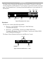
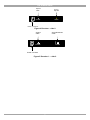
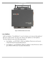
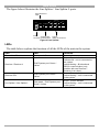
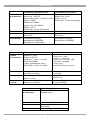
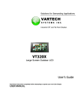
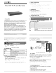
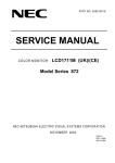
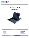
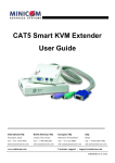
DS Vision 3000
User Guide
w w w . m i n i c o m . c o m
International HQ
North American HQ
European HQ
Jerusalem, Israel
Linden, NJ, USA
Dübendorf, Switzerland
Tel: + 972 2 535 9666
[email protected]
Tel: + 1 908 486 2100
[email protected]
Tel: + 41 44 823 8000
[email protected]
Technical support - [email protected]
5UM40169 V1.2 12/07
DS VISION 3000
Table of Contents
1.
2.
3.
4.
Welcome ........................................................................................................3
Introduction ...................................................................................................4
Features .........................................................................................................4
System components......................................................................................5
System overview ........................................................................................................... 5
Transmitter / Broadcaster ............................................................................................. 5
Receivers....................................................................................................................... 6
Receiver DCL................................................................................................................. 8
Mounting the Receivers ................................................................................................ 8
Line Splitters ................................................................................................................. 9
LEDs ............................................................................................................................ 10
Tuning Unit.................................................................................................................. 11
5.
6.
DS Vision applications ................................................................................11
Pre-installation guidelines ..........................................................................13
Twisted Pair wiring - installation tips.......................................................................... 13
7.
8.
The DS Vision cables...................................................................................14
Connecting the cables.................................................................................15
Broadcaster/Transmitter connections ........................................................................ 15
Receiver /Receiver L connections .............................................................................. 16
Receiver DCL connections.......................................................................................... 16
Connecting CATx cables............................................................................................. 17
Connecting to the power supply................................................................................. 17
9.
10.
11.
Adjusting the picture quality.......................................................................18
DS Vision system management ..................................................................19
Installing the Service utility.........................................................................20
Connecting the Serial Download cable....................................................................... 20
Com port...................................................................................................................... 21
Language..................................................................................................................... 21
12.
Topology ......................................................................................................22
Auto-detect.................................................................................................................. 22
Callouts ....................................................................................................................... 23
Manual ......................................................................................................................... 24
Naming a port.............................................................................................................. 25
Saving a topology ....................................................................................................... 25
Saving a Group............................................................................................................ 25
Deleting a Group ......................................................................................................... 26
13.
Controlling the system ................................................................................27
Selecting the ports to command................................................................................. 27
Control of Receiver DCL monitors.............................................................................. 28
Sending commands .................................................................................................... 28
1
USER GUIDE
14.
15.
16.
Tuning Receivers L/DCL (or Line Splitters/L) via the Service Utility.........29
Remote Tuning ............................................................................................33
Service .........................................................................................................36
Upgrading firmware..................................................................................................... 37
Display Data Channel (DDC) hotkey ........................................................................... 39
Service......................................................................................................................... 39
Broadcaster’s Local Serial port .................................................................................. 39
17.
18.
Security ........................................................................................................40
Technical specifications..............................................................................41
2
DS VISION 3000
1. Welcome
Thank you for buying the DS Vision 3000 system. This system is produced by
Minicom Advanced Systems Limited.
This document provides installation and operation instructions for Minicom’s DS
Vision 3000.
Technical precautions
This equipment generates radio frequency energy and if not installed in accordance
with the manufacturer’s instructions, may cause radio frequency interference.
This equipment complies with Part 15, Subpart J of the FCC rules for a Class A
computing device. This equipment also complies with the Class A limits for radio
noise emission from digital apparatus set out in the Radio Interference Regulation of
the Canadian Department of Communications. These above rules are designed to
provide reasonable protection against such interference when operating the
equipment in a commercial environment. If operation of this equipment in a
residential area causes radio frequency interference, the user, and not Minicom
Advanced Systems Limited, will be responsible.
Changes or modifications made to this equipment not expressly approved by
Minicom Advanced Systems Limited could void the user’s authority to operate the
equipment.
Minicom Advanced Systems Limited assumes no responsibility for any errors that
appear in this document. Information in this document is subject to change without
notice.
No part of this document may be reproduced or transmitted in any form or by any
means, electronic or mechanical, for any purpose, without the express written
permission of Minicom Advanced Systems Limited.
Trademarks
All trademarks and registered trademarks are the property of their respective owners.
User guide feedback
Your feedback is very important to help us improve our documentation. Please email
any comments to: [email protected]
Please include the following information: Guide name, part number and version
number (as appears on the front cover).
2007 © Copyright Minicom Advanced Systems. All rights reserved.
3
USER GUIDE
2. Introduction
The DS Vision 3000 (DS Vision) system from Minicom is an out-of-band solution
for the last step in a digital signage network. DS Vision combines video,
stereo/audio and serial functions for distributing real-time multimedia content from
player to multiple screens up to 600m/2,000ft away.
The DS Vision system distributes Video, Audio and Serial control data from a
single content source to up to thousands of remote monitors over CAT 5/5e/6/7
Twisted Pair media.
The DS Vision system can have up to 10 levels of cascade with literally millions of
connected monitors.
With the DS Vision an administrator can remotely turn the distributed screens on
and off, and monitor them either separately or as a unified group. The system also
supports Display Data Channel (DDC) signaling, enabling optimal player-screen
configuration for better visual experience.
Depending on the cable length the DS Vision broadcasts the video up to resolutions
of 1080p HDTV or 1920x1440 @ 60Hz.
DS Vision comes with full RS-232 point-to-point, real-time serial communication
for the extension of serial devices and player to screen command and information
transfer. All handshake lines are supported for maximum compatibility with any
serial device.
3. Features
·
HD support
·
High quality stereo-audio
·
1 to 1, 1 to many serial control
·
RS232 speeds up to 57,600
·
Distribution over CATx (5/5e/6/7) cable. (Note! Zero skew cables are not
suitable)
·
Multiple mounting options
·
Cascadable
4
DS VISION 3000
4. System components
The DS Vision system consists of the following components:
·
A Transmitter or Broadcaster + cables + power supply
·
Receivers / Receivers L (Long) + power supply
·
Receivers DCL (Dual Cascade Long) + power supply
·
Line Splitters / Line Splitters L (Long) + Tuning cable+ power supply.
·
Tuning unit + cable
·
CD containing Video Service Utility
System overview
The figure below gives an overview of the system, showing a Broadcaster, Line
Splitter L and different Receiver types.
Figure 1 DS Vision system overview
Transmitter / Broadcaster
The Transmitter / Broadcaster come in the following models:
·
Transmitter 1 port – p/n 0VS50005
·
Broadcaster 8 port - p/n 0VS50003
·
Broadcaster 16 port - p/n 0VS50004
5
USER GUIDE
The figure below illustrates the Broadcaster 8 port model. The ports are the same
for the Transmitter and Broadcaster 16 port model, except for the number of System
ports. The Transmitter has 1 System port and the Broadcaster 16 port model has 16
System ports.
Monitor
Local
Serial
Speakers
AU DIO OUT
VIDEO OUT
LOCAL
VIDEO IN
SERIAL
5VDC
C ONTROL
Power
connector
1
2
Serial Download
cable
3
4
5
6
7
System
cables
8
Video
cable
Serial
cable
AUDIO IN
Audio
cable
Figure 2 Broadcaster Unit - 8 port
Receivers
The Receivers come in the following models:
·
Receiver - p/n 0VS50010. Can be up to 110m/360ft from
Transmitter/Broadcaster
·
Receiver L - p/n 0VS50001. Can be up to 300m/1,000ft from
Transmitter/Broadcaster. With a Line Splitter L can be up to 600m/2,000ft
from Transmitter/Broadcaster.
The figures below illustrates the Receiver and Receiver L ports
}
To speakers
L
L&R
R
VIDEO
SERIAL
To Serial device/
connection
To screen
Figure 3 Receiver and Receiver L – side 1
6
DS VISION 3000
System
cable
5VDC
Tuning
adjuster
SYSTEM
TUNING
Power connector
Figure 4 Receiver – side 2
Serial Download
cable
System
cable
5VDC
SYSTEM
TUNING
Power connector
Figure 5 Receiver L – side 2
7
USER GUIDE
Receiver DCL
The Receiver DCL p/n 0VS50006 has the following features:
·
Connects to 2 monitors with each having totally separate video, audio and
serial control
·
Receiver DCL is cascadeable – it has a pass-through port for connecting
more Receivers/ Receivers L/ Receivers DCL
·
Can be up to 300m/1,000ft from Transmitter/Broadcaster
·
With a Line Splitter L can be up to 600m/2,000ft from
Transmitter/Broadcaster
The figures below illustrates the Receiver DCL ports
System
cable In
SYSTEMIN
System
cable Out
5VDC
SERIAL 2
SERIAL 1
SYSTEMOUT
Power connector
To Serial device/
connection 1
To Serial device/
connection 2
Figure 6 Receiver DCL side 1
To stereo Audio
cable of screen 1
To stereo Audio
cable of screen 2
Serial Download
cable
1
TUNING
2
VIDEO 1
AUDIO
To Video
cable of
Screen 1
VIDEO 2
To Video
cable of
screen 2
Figure 7 Receiver DCL side 2
Mounting the Receivers
All Receiver types have VESA standard screw holes 75mm and 100mm apart, see
the figure below. Use the 2 screws supplied (or the screws you may find at the back
of the monitor) to connect the unit to the back of the monitor.
8
DS VISION 3000
100mm
75mm
Figure 8 VESA standard screw holes
Line Splitters
Add Line Splitters / Line Splitters L to use for clusters or to increase the number of
Receivers in the system. You can even connect Line Splitters to Line Splitters.
The Line Splitters come in the following models:
·
Line Splitter - p/n 0VS50001. With Line Splitters, Receivers can be up to
110m/360ft from Transmitter/Broadcaster
·
Line Splitter L - p/n 0VS50002. With Line Splitter L units, Receivers can be
up to 600m/2,000ft from Transmitter/Broadcaster)
9
USER GUIDE
The figure below illustrates the Line Splitter / Line Splitter L ports.
Serial Download
cable
SY STEM OUT
5VDC
TUNING
SYSTEM IN
Power
System cable
connector to Broadcaster
System
cables to Receivers
Figure 9 Line Splitter
LEDs
The table below explains the functions of all the LEDs of the units in the system.
Unit
LED
Function
Transmitter / Broadcaster
Front panel - Green
Receiver / Receiver L
RJ45 System port. Green /
Yellow
Power indicator
Green - Power indicator
Yellow solid – unit is connected to
the system.
Yellow blinking – Bi-directional
RS232 communication (only
possible with one Receiver /
Receiver L at a time).
Receiver DCL
RJ45 System port. Green /
Yellow
Green - Power indicator
Yellow blinking – unit is connected
to the system
Line Splitter / Line Splitter L
Rear panel - RJ45 System port.
Green / Yellow
Green - Power indicator
Yellow blinking – unit is connected
to the system
10
DS VISION 3000
Tuning Unit
The optional Tuning Unit p/n 0VS50008 is used to manually tune Receivers L /
Line Splitters or to download preset tuning parameters. The figure below illustrates
the Tuning Unit.
Figure 10 Tuning Unit
5. DS Vision applications
The figures below illustrate the versatility of the DS Vision system.
Figure 11 shows a basic installation with a Receiver and Receiver L. Receivers can
be up to 110m/360ft away from the Transmitter/Broadcaster. Receiver L can be up
to 300m/1,000ft away from the Transmitter/Broadcaster
Receiver
110m/360ft
Player
Receiver
Long
300m/1,000ft
Transmitter/Broadcaster
Figure 11 DS Vision basic installation
Figure 12 shows a Line Splitter with connected Receivers up to 110m from the
Transmitter/Broadcaster.
Player
Receivers
Line Splitter
100m/330ft
10m/33ft
Transmitter/Broadcaster
Figure 12 Short cluster
Figure 13 shows a Line Splitter L with connected Receivers up to 400m from the
Transmitter/Broadcaster.
11
USER GUIDE
Player
100m/330ft
Receiver
300m/1,000ft
100m/330ft
Line Splitter Long
Transmitter/Broadcaster
Receiver
Figure 13 Long cluster
Figure 14 and Figure 15 show different mixed installations with different
combinations of Line Splitter and Line Splitter L and Receiver and Receiver L.
Receiver
Player
Line Splitter
10m/33ft
100m/330ft
Transmitter/Broadcaster
200m/660ft
Receiver
Long
Figure 14 Mixed installation 1
Receiver
Player
100m/330ft
300m/1,000ft
300m/1,000ft
Line Splitter Long
Receiver Long
Transmitter/Broadcaster
Figure 15 Mixed installation 2
Figure 16 shows a Receiver DCL 300m/1,000ft away from the player with 2
connected monitors.
Player
Receiver DCL
300m/1,000ft
Transmitter/Broadcaster
Figure 16 Receiver DCL
Figure 17 shows a Receiver DCL 600m/2,000ft away from the player connected via
a Line Splitter L.
Player
300m/1,000ft
Transmitter/Broadcaster
300m/1,000ft
Line Splitter Long
Figure 17 Line Splitter L + Receiver DCL
12
Receiver DCL
DS VISION 3000
Figure 18 shows a Line Splitter L cascaded to a Receiver DCL.
Receiver
DCL
Player
300m/1,000ft
100m/330ft
200m/660ft
Line Splitter Long
Receiver DCL
300m/1,000ft
Receiver
DCL
Transmitter/Broadcaster
Figure 18 Receiver DCL + Line Splitter L
Figure 19 shows two Receiver DCL units cascaded to 300m/1,000ft. (You can
cascade up to 10 levels of Receiver DCL / Line Splitters).
Player
Receiver DCL
Receiver DCL
100m/330ft
200m/660ft
Transmitter/Broadcaster
Figure 19 Cascaded Receivers DCL
6. Pre-installation guidelines
Place cables away from fluorescent lights, air conditioners, and machines that are
likely to generate electrical noise.
Twisted Pair wiring - installation tips
·
The minimum recommended bend radius for Twisted Pair cable is 4 cm.
·
Don’t twist the Twisted Pair cable.
·
Don’t over tighten wire ties.
·
Don’t bend the Twisted Pair cable more than 90 degrees.
·
Don’t use a stapler for installation.
·
Don’t stretch or apply a pull-force greater than 11 kg.
13
USER GUIDE
7. The DS Vision cables
The DS Vision cables are illustrated below. All these cables connect to the
Broadcaster/Transmitter and player.
VGA cable
p/n 5CB40056
Serial Download cable
p/n 5CB40419
Serial Extender cable
p/n 5CB40515
Stereo Plug cable
p/n 5CB40027
Figure 20 Broadcaster/Transmitter cables
14
DS VISION 3000
8. Connecting the cables
The connections illustrated in Figure 21 are described below. The detailed
connection of the Receiver DCL is illustrated in Figure 22.
To local Serial
device
Serial Download cable
DS Vision 3000
Broadcaster
To Serial port
To Audio Out
To Serial port
AUDIO OUT
VIDEO OUT
LOCAL
VIDEO IN
SERIAL
To Line
Out port
5VDC
CONTROL
1
2
3
4
5
6
7
8
To
Video
In
CATx cables to
*Receivers or
Line Splitters/L
AUDIO IN
To
Serial
port
To Audio In
Stereo Audio cable
Serial Extender cable
Video cable
Player
computer
Line Splitter
SYSTEM OUT
5VD C
T UNIN G
SYSTEM IN
CATx cables to
*Receivers or Line
Splitters/L
Receiver side 1
5VDC
SYSTEM
SYSTEM
Receiver side 2
TUNING
TUNING
L
L&R
R
SERIAL
VIDEO
Video
* Receivers refers to any
of the following:
Receivers
Receivers L
Receivers DCL
Speakers /
Audio
Serial port /
device
Figure 21 Connection diagram
Broadcaster/Transmitter connections
1.Connect the Video cable to the Broadcaster/Transmitter Video In port and the
Computer’s Video card.
2. Connect the Serial Extender cable to the Broadcaster/Transmitter Serial port and
the Computer’s Serial port.
15
USER GUIDE
3.Connect the Stereo Audio cable to the Broadcaster/Transmitter Audio in port and
the Computer’s Line Out port.
4.To use the Video Service Utility, connect the Serial Download cable to the
Broadcaster/Transmitter Control port and the Computer’s Serial port.
5. (Optional) Connect a monitor to the Broadcaster/Transmitter Video Out port.
6.(Optional) Connect speakers to the Broadcaster/Transmitter Audio Out port.
7.(Optional) Connect a local Serial device to the Local port.
Receiver /Receiver L connections
1.Connect the screen to the Video port.
2.Connect the audio/speakers to the Audio port/s. Where the audio/speakers have
one stereo connector, connect it to the L&R port. Where the audio/speakers have
two connectors for right and left channels, connect them to the L port and the R
port.
3.Where relevant connect the Serial connection to the Serial port.
Receiver DCL connections
1.Connect one screen to Video port 1 and another screen to Video port 2.
2.Connect the audio/speakers of the first screen to stereo Audio port 1 and connect
the audio/speakers of the second screen to stereo Audio port 2. Ensure that the
Video and Audio ports are connected to the same numbers, i.e. one screen to
Video and Audio ports 1 and the other screen to Video and Audio ports 2.
3.Where relevant connect the Serial connection to the Serial ports 1 and/or 2.
See the detailed connections below.
16
DS VISION 3000
System In
CATx cable from
Transmitter/Broadcaster or
Line Splitter/L or Receiver
DCL unit
Screen 1
System Out
CATx cable to Line Splitter/L
or Receiver* unit
Screen 2
Serial port /
device
Receiver
DCL side 1
SYSTEM IN
SYSTEM
SERIAL 1
SYSTEM OUT
1
Video
Speakers /
Audio
Receiver
DCL side 2
TUNING
SERIAL 2
Serial port /
device
TUNING5VDC
2
AUDIO
VIDEO 1
VIDEO 2
Video
Speakers /
Audio
* Receivers refers to any of the following:
Receivers
Receivers L
Receivers DCL
Figure 22 Receiver DCL connections
Connecting CATx cables
The connections are illustrated in Figure 21 and Figure 22 above.
Connecting the Broadcaster/Transmitter
Connect CATx cables to the System ports of the Broadcaster/Transmitter and the
System In ports of Receivers/L/DCL or Line Splitters/L.
Connecting/cascading a Line Splitter/L
Connect CATx cables to the System Out ports of the Line Splitter/L and the System
In ports of Receivers/L/DCL or further Line Splitters/L.
Cascading a Receiver DCL
Connect a CATx cable to the System Out port of the Receiver DCL and the System
In port of a Receiver/L/DCL or Line Splitter/L.
Connecting to the power supply
Connect the Transmitter/Broadcaster and all Receiver and Line Splitter units to the
power supply using the AC/DC adapters provided. If using third party power
adapters, ensure correct polarity (Center negative) and voltage – see the Tech
specs.
Once the system is connected the DS Vision system broadcasts to all remote
monitors/speakers. Note! You can use the Service Utility provided to broadcast
content to specific monitors or groups of monitors, see DS Vision system
management on page 19 below.
17
USER GUIDE
9. Adjusting the picture quality
When the broadcasted picture needs adjusting:
For the Receiver turn the Tuning adjuster – see Figure 4, using a small screwdriver.
The Receiver L/Receiver DCL/Line Splitters can be tuned either via the Service
Utility, as explained on page 29, or by using the optional Tuning Unit as explained
below.
Note! Where there are cascaded Receiver DCL/Line Splitters you must tune them
from the unit nearest the Broadcaster/Transmitter onwards. See diagram below.
Transmitter/Broadcaster
Line Splitter
Receiver DCL
Line Splitter
Receiver DCL
Receiver DCL
4th
5th
Player
1st
2nd
3rd
Tune units in the order shown by the arrow
1.Connect the Video Tuning Unit cable (p/n 5CB40607) to the Tuning Unit and the
Receiver L/Receiver DCL/Line Splitter Tuning port. Once connected, Ready to
Tune appears in the LCD.
By pressing the Menu key you repeatedly scroll between the following functions:
·
Tables
·
Red
·
Green
·
Blue
·
Brightness
·
HF Emph
·
Save / ESC
You adjust a function by pressing the up and down arrow keys.
Tables
The video tables contain preset tuning configurations for distances of between 1m
and 300m. Note! These presets were made using a test cable which may not be an
exact match for the cable that you are using.
18
DS VISION 3000
Choose the preset distance closest to the actual distance in meters between the
Player and remote screen. This will give you a fairly accurate tuning, which can be
further finely tuned using the other functions of the Tuning Unit.
To tune an image:
1.Scroll to Tables
2.Use the arrow keys to browse through all the predefined tables.
3.When you reach the desired table, press the Menu key. MNU=SAVE appears in
the LCD and the table downloads. During downloading the LCD message blinks.
4.If the tuning is not at all satisfactory, select and download a different table.
5.Once the adjustment is satisfactory, press the Menu key to scroll to next function.
Note! For the Receiver DCL both the connected screens receive the same tuning
adjustments.
Saving and exiting
To save all settings in the Receiver L/DCL or Line Splitter unit:
1.Scroll to Save / ESC
2.Press the up arrow to save all changes and exit or press the down arrow to
disregard all changes and exit.
10. DS Vision system management
The DS Vision system comes with a Service utility to configure and control the
system. Use the Service utility to:
·
Define up to 16 Groups of monitors – (a specific monitor may belong to
several Groups).
·
Broadcast/disconnect video and/or audio and/or serial data to each monitor
or to Groups of monitors.
·
View system topology and switching status of each monitor.
·
Remotely tune a monitor.
·
Upgrade each system component firmware or FPGA
·
Configure DDC settings (read, save and store in Transmitter)
·
Return to the factory default settings
19
USER GUIDE
11. Installing the Service utility
The Service utility is located on the supplied CD and on our website
www.minicom.com in the Support section.
Install the Service utility on a computer with the following system requirements:
·
Intel® Pentium® II or equivalent processor
·
Windows XP Professional, Home Edition, or Tablet PC Edition with Service
Pack 2; Microsoft® Windows® 2000 with Service Pack 4; Windows 2003
Server; or Windows Vista™
·
128MB of RAM
·
10MB of available hard-disk space
For full functionality of the Service utility the DS Vision system
(Broadcaster/Transmitter, Line Splitters and Receivers) must be connected and
switched on. You can however configure the system topology manually even when
the system is not operational.
Connecting the Serial Download cable
Connect the Serial Download cable to the Control port of the
Transmitter/Broadcaster and a Serial port of the computer which has the Service
Utility installed.
AUDIO OUT
VIDEO OUT
LOCAL
VIDEO IN
SERIAL
5VDC
CONTROL
1
2
3
4
5
6
7
8
AUDIO IN
To computer’s
Serial port
Serial
Download
cable
Figure 23 Connecting the Serial Download cable
To open the Service Utility, choose Start/Programs/DS Vision 3000 Service Utility/
DS Vision 3000 Service Utility. The Control window appears, see Figure 24.
20
DS VISION 3000
Figure 24 Control window
Com port
Choose Tools/Options. The Preferences window appears see Figure 25. In the Com
port field select the Com port to which the Serial Download cable is connected to.
Figure 25 Preferences window
Language
In the Preferences window above, you can change the language of the Service
Utility GUI to be: Chinese, French German, Italian, Portuguese, Russian, Japanese
or Ukrainian.
To change the language:
1.From the Language drop-down menu, select the desired language.
2.Press OK.
3.Close the Service Utility.
4.Reopen the Service Utility. Now all windows appear in the selected language.
21
USER GUIDE
12. Topology
To utilize the Service Utility functions you must configure the system topology. To
configure the system topology, click the Topology tab* or select View/ Topology.
(*For some operating systems the tabs on the Service Utility need to be doubleclicked).
The following appears.
Title line
(Indicates if the
Utility is online
or offline)
Figure 26 Topology tab
You can detect the topology automatically or configure it manually.
Auto-detect
Note! Auto-detection only works if the Service Utility is online. Check the Title
line of the Service Utility window, see Figure 26. When offline, connect to the
system by choosing File/Connect.
To auto-detect the topology, click
and when prompted click Yes.
A detected topology appears on the left showing all connected DS Vision units, as
in the following figure.
22
DS VISION 3000
Figure 27 Auto-detected topology
Note! You can detect the current topology at any time by pressing
This fully updates all connected and disconnected ports.
.
Note!
Auto-detect deletes all names given to particular ports. Naming ports is explained
on page 25.
Callouts
Hold the mouse over any of the rows in the menu tree or over any button. A callout
appears with information about the device or button function. For example in the
figure below, the callout shows the device type connected to the port, which port it
is connected to, the level of connectivity i.e. the number of levels of Line Splitters
or Receiver DCL units it is connected through. The status of the video, audio and
serial signals and the bi-directional serial status.
Figure 28 Callout
23
USER GUIDE
Check
When units have been connected or disconnected since last detecting the topology
you can check for any changes to the topology.
To do so:
1.Click
undefined
. Any new units detected appear as connected but
. You must still define the unit.
2.To manually define the units connected to the ports, click the checkbox of a port
or a number of ports that have the same device connected.
3.Click
. A drop-down menu appears.
4.Select the device type. Note! When the device is a Line Splitter, repeat the
process of defining the connected devices for each port of the Line Splitter.
Note! Check does not update the topology, it detects any new connections and units
.
that are disconnected appear with a yellow exclamation mark
Update
To add new devices to the present topology click
. The new devices
appear. Units that are disconnected appear with a yellow exclamation mark
.
Manual
You can display the topology manually whether the system is online or offline.
To display the topology manually:
1.Click
. A drop-down menu appears.
2.Select the connected Transmitter/Broadcaster. The selected topology appears on
the left, see Figure 29. If the Service Utility is online you can see which ports
have devices connected. In Figure 29 a device is connected to port 6.
24
DS VISION 3000
Figure 29 Manually displayed topology
3.To define the units connected to the ports, click the checkbox of a port or a
number of ports that have the same device connected.
4.Click
. A drop-down menu appears.
5.Select the device type. Note! When the device is a Line Splitter, repeat the
process of defining the connected devices for each port of the Line Splitter.
Naming a port
To give a port an identifying name:
1.Check the port number (ensure that no other ports are checked). In the manual
section, Set device name: appears.
2.Type a new name for the port - You can give ports identical names. This name
appears immediately on the left.
Saving a topology
To save a topology choose File/Save or Save as. Save the topology.
To restore the topology choose File/Restore. Find the saved topology and click
Open. The stored topology appears. Note! The most recent saved topologies appear
in the File menu.
Saving a Group
You can save a Group to include particular ports. Once defined, you can send
instructions to the defined Group without needing to choose the individual ports.
To save a Group:
25
USER GUIDE
1.Select the ports you want to include in the Group.
2.Click
. The Enter name box appears.
3.Type a name for the group and click OK. The Group appears on the left.
Groups appear
here
Figure 30 Saving a Group
To see the selected ports of a Group, hold the mouse over the Group name or folder
or check box, a callout appears showing the selected ports.
Deleting a Group
To delete a Group:
Select the Group and click
.
26
DS VISION 3000
13. Controlling the system
To control the system:
Click the Control tab or choose View/Control, the Control window appears, see
Figure 31.
Control
buttons
Connected
devices
appear here
Topology
Figure 31 Control window
The table below explains the functions of the Control buttons:
Button
Function
Video broadcasting to remote unit
Audio broadcasting to remote unit
Serial command to remote unit
Bi-directional Serial command
Selecting the ports to command
You can select the ports to command in any of the following ways.
From the topology on the left hand side:
Tick the individual checkboxes of the units you want to send a command. Or tick
the desired Group – all commands will then be sent to all units in the Group.
27
USER GUIDE
From the icons on the right hand side:
Click an icon to select it. To select more than one icon, hold down Shift or Ctrl and
select the desired icons.
Selecting all
To select all:
Choose Edit/Select All.
Control of Receiver DCL monitors
The two monitors connected to a Receiver DCL are controlled completely
independently. Figure 32 shows the two monitors connected to a Receiver DCL.
They are separate and clearly defined as [1] and [2]. Just select the desired port or
icon as you would for any other Receiver. In the topology you can also see the
Receiver connected to the pass-through port.
Pass-through
port for
connecting more
Receivers
Receivers DCL
ports 1 &2
Figure 32 Control of Receiver DCL monitors
Sending commands
Once the desired units are selected send the desired command by pressing the
appropriate Control button. By default all signals (video, audio, serial) are
broadcast.
28
DS VISION 3000
Sending/blocking video
Click
to toggle between sending and blocking video. When receiving video
the device icons appear like this:
.
When not receiving video the device icons appear like this:
.
Sending/blocking Audio
Click
to toggle between sending and blocking audio. When receiving audio
the device icons appear with a speaker like this:
.
Sending/blocking a Serial command
Click
to toggle between sending and blocking a Serial command. When
sending a Serial command the device icons appear with an arrow like this:
.
Sending/blocking a bi-directional Serial command
When sending a Serial command, you can send a bi-directional Serial command to
a single Receiver/L or to one monitor connected to a Receiver DCL.
Click
to send the bi-directional Serial command. The device icon appears
with a double arrow like this:
. Click again to block the bi-directional Serial
command. You can then send the bi-directional Serial command to a different
Receiver/L monitor connected to a Receiver DCL.
14. Tuning Receivers L/DCL (or Line Splitters/L) via the Service
Utility
You can tune the Receivers L/DCL/Line Splitters L with the Service Utility from
the Transmitter/Broadcaster position or from the unit itself. The advantage of tuning
from the Receiver L/Receiver DCL, is that you can see the tuning on the screen as
you perform it. From the Line Splitter position you can be closer to the screen than
from the Transmitter/Broadcaster position.
29
USER GUIDE
To tune from the Transmitter/Broadcaster position:
Connect the Serial Download cable to the Control port of the
Transmitter/Broadcaster and the Serial port of a computer which has the Service
Utility installed.
To tune from the Receiver L/DCL or Line Splitter/L position:
Connect the Serial Download cable to the units Tuning port and the Serial port of a
computer containing the Service Utility. See the figure below.
Note! For the Receiver DCL both the connected screens receive the same tuning
adjustments.
5VDC
SYSTEM
TUNING
To computer’s
Serial port
To
Transmitter
Serial Download cable
Figure 33 Connecting the Serial Download cable to the Receiver L
1.Open the test card located on our website www.minicom.com/support/skew.png
or www.minicom.com/support/skew.gif or, on the supplied CD. Or open the
Service Utility and choose Tools/Options, the Preferences window appears, see
Figure 25 above. Check Show Skew Picture. When you click the Tuning tab the
test card appears in the background. See Figure 34. This image will help you get
the best screen image. It can also help to correct skew.
Note! From a Line Splitter position you can only adjust luminance and
equalization. Adjusting skew delay also, can be done from a Receiver L/DCL or
Line Splitter L position.
30
DS VISION 3000
Figure 34 Test card
2.Click the Tuning tab or select View/Tuning. The Tuning window appears see
Figure 35 and Figure 36.
Figure 35 Tuning window from Transmitter position
31
USER GUIDE
Figure 36 Tuning window from Line Splitter L position
3.The Drop-down menu contains preset tuning configurations for distances of
between 1m and 300m. Note! These presets were made using a test cable which
may not be an exact match for the cable that you are using. Choose the preset
distance that is closest to the actual distance in meters between the Player and
remote screen.
4.For fine tuning use the sliding bars to adjust the image. The bars are as follows.
Luminance – image brightness
Equalization – image sharpness
Red, Green, Blue
Red, Green and Blue are for red, green and blue delay. When transmitting video
over Twisted Pair cables a horizontal misalignment (skew) between the red, green
and blue components inevitably occurs. This is because the different length of each
pair causes the signals to reach the monitor at different times.
To see which signal is slower or faster look at the test card and see which of the
colors are not aligned. For example in Figure 37, red is the slowest color. You
would therefore delay green and blue until they align with red.
32
DS VISION 3000
Faster
Red
Green
Blue
Slower
Figure 37 RGB signals
5.Once you have a satisfactory image, press Store to keep the present tuning
configuration in the device memory.
Restore – If after changing values you change your mind, you can restore the
values to how they were the last time the Store button was pressed by pressing
Restore.
The current tuning parameters can be saved and used later for the same device, or
another device connected with the same cable length and type.
To do so:
1.Click Save Preset to save the tuning configuration on the computer. The Enter
Name box appears.
2.Type a name for the preset and click OK. The tuning configuration now appears
in the drop-down menu.
Delete preset - to delete a tuning configuration from the drop-down menu, click
Delete preset.
15. Remote Tuning
You can tune the Receiver L, Receiver DCL and Line Splitters from any laptop or
other mobile device via a web browser. Through the browser you access the player
running the Service utility via the local network. This enables you to tune the screen
when standing in front of it without the need to be physically connected to the
Receiver L/Receiver DCL/Line Splitter. Note! For the Receiver DCL both the
connected screens receive the same tuning adjustments.
The Service Utility must be installed on the players but is not needed on the remote
tuning device. Figure 38 illustrates the basic concept.
33
USER GUIDE
http://192.168.111.132
Remote tuner at the
screen
LAN
DS Vision Service
Utility installed here
Broadcaster
Receivers
Line Splitter
Player - IP: 192.168.111.132
Figure 38 Remote tuning
At the player the setup is done as follows:
1.Connect the Serial Download cable to the Broadcaster/Transmitter and player.
2.Open the Service Utility and choose Tools/Options, the Preferences window
appears, see Figure 25 above.
3.Select the Enable Remote Control checkbox, the software starts a small web
server in the background allowing other computers on the network to access it.
The Check Remote Control button un-grays. Click the button to display a local
browser to indicate that the remote option is enabled and functioning.
4.To verify the IP address of the player, click Start/Run, type “cmd” press Enter,
type “ipconfig” press Enter. The IP address appears.
The tuning at the remote laptop/device is done as follows:
1.Open a browser and type the IP address of the player. For example in Figure 38
the remote tuner accesses the tuning facility by typing the IP address
http://192.168.111.132.
2.Press Enter. A list of all Receivers L, Receivers DCL and Line Splitters
connected to the player appears, see Figure 39.
34
DS VISION 3000
Figure 39 Select device web page
3.Select a unit and press Submit. The tuning page appears, see Figure 40.
Figure 40 Remote tuning web page
4.Adjust the settings until you have a satisfactory picture. Press Submit to activate
the new values. Press Store to save the new values. After changing values you
can still return to the original settings, or to the settings from the last time you
pressed Store by pressing Restore.
5.Press reset to return to the default values.
35
USER GUIDE
6.Select another device to tune by clicking Select another device or close the
webpage.
Figure 41 gives an overview of the remote tuning.
The DS Vision 3000 Service Utility is
running in “Remote” mode on the
player (or on another computer)
connected to the Broadcaster. This
computer is attached to LAN and
already has an IP Address.
(for example 192.168.111.132)
TFT450
Digital Signage
Digital
Digital Signage
Signage
Www.too-high-to-reach.com
Www.too-high-to-reach.com
Www.too-high-to-reach.com
SD
IP: 192.168.111.132
The “Remote control”
mode turns on the builtin web service in the
control utility
Http://192.168.111.132
Figure 41 Remote tuning setup
16. Service
You can do the following from the Service window:
·
Upgrade firmware
·
Configure DDC settings
·
Return to the factory default settings
·
Configure the Broadcaster’s Serial port
Click the Service tab, the service window appears, see Figure 42.
36
DS VISION 3000
Figure 42 Service window
Upgrading firmware
Upgrade firmware to improve functionality and fix bugs. Firmware updates can be
found on the Minicom website www.minicom.com in the Support section under
Product Upgrades. For specific upgrade information on the DS Vision 3000 system
see explanations and release notes of each firmware version.
1.Save the firmware update on your hard drive and unzip it to a temporary folder.
2.Verify the system topology by clicking on the Detect button in the Topology tab
and note the number of levels and units connected to the system.
3.Go to the Service window and check the current Firmware and FPGA versions of
all units by clicking the Query button and selecting Firmware or FPGA, see
Figure 43. The version appears in the Version line, see Figure 44.
Click here for F/W
version
Click here for
FPGA version
Figure 43 Query button
37
USER GUIDE
Figure 44 Version line
4.Select the unit you want to upgrade.
5.Click Update. The Open box appears.
6.Select the firmware file with the extension .hex, and click Open, the firmware
upgrades.
7.Once the firmware upgrade finishes, press Update again. In the Files of type:
drop-down menu, select “DS Vision core FPGA Firmware (*.mcs)”, see below.
Select here:
DS Vision core FPGA Firmware (*.mcs)
Figure 45 *.mcs extension file
8.Select the FPGA file with the .mcs extension, see Figure 46 and click Open, the
FPGA upgrades.
Figure 46 FPGA file with the .mcs extension
38
DS VISION 3000
Display Data Channel (DDC) hotkey
Display Data Channel (DDC) is a VESA standard for exchanging information
between a monitor and a video adapter.
Update the DDC during the initial installation of the system, this will enable
emulation of the selected monitor DDC information to the computer when it boots
the next time.
To update the DDC:
1.Select a Receiver and press Get DDC to read the DDC from the monitor attached
to it and save it to file.
2.Select the Transmitter/Broadcaster and press Set DDC to read from the saved file
and upload it to the Transmitter/Broadcaster.
Get stored DDC button – Get the DDC stored in the Transmitter/Broadcaster flash
memory and save it as a file on the computer’s hard disk. Note: This is the DDC
data that will be read by the player connected to the Transmitter/Broadcaster.
Service
To restore factory defaults, select the desired device and press Restore to factory
settings. Note! All configuration and tuning adjustments will be lost.
Broadcaster’s Local Serial port
This is for serial control of the local monitor. By default serial control is disabled.
Enable – Press Enable to connect the system serial data to the local monitordownstream only.
Bi directional – Once serial control is enabled you can press Bi directional to
enable a serial bi-directional connection with the local monitor – like any remote
monitor in the system.
39
USER GUIDE
17. Security
Choose Tools/Options. In the Preferences window click Security. The Security
screen appears.
Figure 47 security window
Here you can set up a password to require password access to the service Utility.
40
DS VISION 3000
18. Technical specifications
Resolution
HDTV up to 1080p.
Up to 1920x1440 @ 60Hz.
Depending on the cable quality
Input/Output video signals
Analog signal red, green, blue 0.7v, p-p 75 Ohm
Sync
TTL compatible
Horizontal/Vertical sync polarity
Positive/Negative
System cable
CATx(5/5e/6/7) UTP/FTP 2x4x24 AWG solid wire cable
Maximum distance
300m / 1,000ft
Skew compensation
Up to 63 nsec
DDC
Complies with VESA DDC 2 specifications
RS232 connection
Serial signals = RXD, TXD, DTR, DSR, RTS, CTS
Serial baud rate
Up to 57,600 bps
Audio
Stereo
Frequency response: 20 Hz to 20 kHz, +/-1 dB.
Signal-to-Noise Ratio (SNR): 80 dBA.
Total Harmonic Distortion and Noise (THD+N): 0.017%.
Stereo crosstalk: -70 dB.
Input impedance: 10k Ohms.
Line level output; supports multimedia speakers.
Maximum I/O levels: 3.1Vp-p (line level).
Serial
Broadcaster / Transmitter – DCE
Receivers - DTE
Recommended cables
Belden 1583 ENH UTP CAT 5E 4PR
Belden 1633 ENH FTP CAT 5E 4PR
Operating temperature
5°C to 40°C / 41°F to 104°F
Storage temperature
-40°C to 70°C / -40°F to 158°F
Warranty
3 years
41
USER GUIDE
Cables
& Connectors
Dimensions
Power
Order Number
Transmitter, Broadcaster 8/16
Line Splitter/Line Splitter L
VGA In - HDD15M
VGA Local - HDD15F
Stereo audio In/Out – Jack PL 3.5mm
Serial In- DB9F
Serial Local- DB9M
System Out -1/8/16 RJ45
Control – RJ11
Power LED – Green (front panel)
292.5x 153.6x41.5mm
External Adaptor
5VDC 2.5A
Transmitter 0VS50005
Broadcaster 8 0VS50003
Broadcaster 16 0VS50004
System In - RJ45
System Out - RJ45
Control – RJ11
Power LED – Green (front panel)
138x153.7x41.5mm
External Adaptor
5VDC 2.5A
Line Splitter 0VS50009
Line Splitter L 0VS50002
Receiver/Receiver L
Receiver DCL
Cables
& Connectors
System In - RJ45
Screen - HDD15F
Audio Out – 3 Jack L,R, L&R
Serial Out- DB9M
Tuning- potentiometer / RJ11
Power LED – Green (on RJ45)
System In - RJ45
System Out - RJ45
Screen – 2 x HDD15F
Audio Out -2x 3.5 Jack , L&R
Serial Out- 2 X DB9M
Tuning- RJ11
Power LED-Green (on RJ45)
Dimensions
147x 145x26mm
(including mounting)
External Adaptor
5VDC 1 or 2.5A
Receiver 0VS50010
Receiver L 0VS50001
152x145x26mm (including
mounting)
Power
Order
number
Cables
& Connectors
Dimensions
Power
Order number
External Adaptor
5VDC 2.5A
Receiver DCL ( Dual Cascade
Long) 0VS50006
Video Tuning Unit
To Receiver- RJ11
3 button tuning
93.7x62.1x28mm
Powered from the Receiver or
Line Splitter
Video Tuning Unit 0VS50008
42
DS VISION 3000
Regional Offices
Germany
France
Italy
Kiel
Vincennes
Rome
Tel: + 49 431 668 7933
[email protected]
Tel: + 33 1 49 57 00 00
[email protected]
Tel: + 39 06 8209 7902
[email protected]
England
Tel: + 44 121 288 0608
[email protected]
www.minicom.com
43