1
1
WTMC Gas & Electric Dryer Training
Manual
WTMC GAS & ELECTRIC DRYER TRAINING
MANUAL
1st Edition/Revision 4 (1/19/04)
2
WTMC Training Program
•
•
•
•
•
•
•
•
•
Features and Benefits
Product Description
Warranty
Installation
Operation
Disassembly
Reassembly
Wiring Diagram
Service Tips
1st Edition/Revision 4 (1/19/04)
3
Features and Benefits
• Drying rack for sweaters & shoes (standard on
WTMC6300/6500 & optional on WTMC3300).
• Smooth stainless steel drum - won’t rust & is
gentle to clothes.
• Auto-dry with digital moisture sensor and 2
temperature sensors.
• Moisture and temperature sensors automatically
determine when laundry is dry, preventing overdrying and damaging clothing.
• Vented dryers (more efficient than condensation
dryers)
• Regular/Cotton - 4 settings
• Permanent Press - 3 settings
• Empty drum detection
• UL listed (U.S. & Canada)
1st Edition/Revision 4 (1/19/04)
4
Product Description
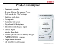
• Electronic controls
• Regular/Cotton, Permanent Press,
Delicates & Air Fluff settings
• Stainless steel drum
• Drying rack
• Extra-fine lint screen
• Digital and LED displays
• Adjustable end of cycle signal
• Vented dryers
• Interior drum light
• Electric (WTMC3300/6300US) and gas
(WTMC6500UC) versions
• Empty drum detection
• UL listed (U.S. & Canada)
Auto or timed dry settings
Electronic controls
Digital &
LED displays
Easily accessible
extra-fine lint
screen
Electric &
gas versions
Interior
drum
light
1st Edition/Revision 4 (1/19/04)
5
Warranty
Bosch Dryers Limited Lifetime Warranty
Statement of Limited Warranty
The warranties provided by BSH Home Appliances ("Bosch") in this Statement of
Warranties apply only to Bosch clothes dryers sold to the first using purchaser by Bosch
or its authorized dealers, retailers or service centers in the United States or Canada. The
Warranties provided herein are not transferable, and take place from date of installation
or ten business days after delivery date, whichever comes first.
1 Year Full Limited Warranty
Bosch will repair or replace, free of charge, any component part that proves defective
under conditions of normal home use, labor and shipping costs included. Warranty
repair service must be performed by an authorized Bosch Service Center.
2 Year Limited Warranty
Bosch will provide replacement parts, free of charge, for any component part that
proves defective under conditions of normal home use, shipping costs included, labor
charges excluded.
For location of nearest repair depot call 1-800-944-2904 from 5:00 AM - 5:00 PM M-F
(Pacific time)
1st Edition/Revision 4 (1/19/04)
6
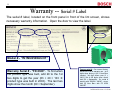
Warranty -- Serial # Label
The serial # label, located on the front panel in front of the lint screen, shows
necessary warranty information. Open the door to view the label.
Model # - “WTMC6500UC/01”
Warranty Serial # - “FD 8309”. To find when
the product type was built, add 20 to the 1st
two digits to get the year (83 + 20 = 103 Æ
product type was built in 2003). The last two
digits show the month (09 = September).
Factory serial # - Can convert factory
serial # to FD # for warranty use. 1st 2
digits show factory # (85 = New Bern
laundry), 3rd digit shows year (3 =
2003), 4th & 5th digits show month
built (09 = September). So, serial #
starting with “853090…00040” = dryer
built @ New Bern with FD 8309
000040.
1st Edition/Revision 4 (1/19/04)
7
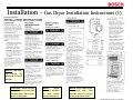
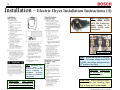
Installation – Gas Dryer Installation Instructions (1)
NOTE: Be sure
to follow all
national & local
codes.
CAUTION: When moving
a dryer, screw in the feet
(leveling legs) first so they
won’t be damaged.
NOTE:
Dryers
must be installed
on level, solidly
constructed floors.
NOTE: Don’t install dryers
in closets with solid
wooden doors as dryers
must have make-up air.
1st Edition/Revision 4 (1/19/04)
8
Installation -- Gas Dryer Installation Instructions (2)
CAUTION: Dryers must be grounded
to reduce the risk of shock.
1st Edition/Revision 4 (1/19/04)
9
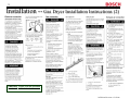
Installation -- Gas Dryer Installation Instructions (3)
No kit needed
NOTE: Use 4” metal duct (flexible
or rigid) with these dryers. Do not
use non-metal duct.
HINT: Don’t exceed
maximum duct lengths
shown in table.
HINT:
Using side exhaust kit requires
precision cutting of side panel so duct will line
up properly and will clear motor. Only right
side venting (viewing front of dryer) is possible.
HINT: Use as few elbows as possible.
1st Edition/Revision 4 (1/19/04)
10
Installation -- Gas Dryer Installation Instructions (4)
HINT: Be careful to not
throw
away
any
accessories or manuals
during
unpacking
or
installation
(including
wrenches or installation
instructions).
CAUTION: Dryers must
be grounded to reduce
the risk of shock.
CAUTION: When moving
a dryer, screw in the feet
(leveling legs) first so they
won’t be damaged.
1st Edition/Revision 4 (1/19/04)
11
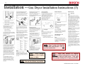
Installation – Electric Dryer Installation Instructions (1)
NOTE:
Be
sure to follow
all national &
local codes.
NOTE: Dryers must be installed
on level, solidly constructed floors.
CAUTION: When moving a dryer,
screw in the feet (leveling legs)
first so they won’t be damaged.
NOTE: Don’t install dryers in
closets with solid wooden doors as
dryers must have make-up air.
1st Edition/Revision 4 (1/19/04)
12
Installation – Electric Dryer Installation Instructions (2)
IMPORTANT: 240V electric dryers must be
connected to a neutral or else they won’t work.
CAUTION: Dryers must be grounded to reduce the risk of shock.
1st Edition/Revision 4 (1/19/04)
13
Installation – Electric Dryer Installation Instructions (3)
HINT: Using side exhaust kit requires
precision cutting of side panel so duct
will line up properly and will clear
motor.
Only right side venting
(viewing front of dryer) is possible.
HINT: Use as few
elbows as possible.
HINT: Don’t exceed
maximum duct lengths
shown in table.
HINT: Dryers can be run on
240V or 208V. To change
voltage from 240V to 208V,
use voltage changeover test
(8th position from right).
NOTE: Use 4” metal duct (flexible
or rigid) with these dryers. Do not
use non-metal duct.
1st Edition/Revision 4 (1/19/04)
14
Installation – Electric Dryer Installation Instructions (4)
HINT: Canadian dryers
use a NEMA 10-30P
240V, 30A, 4-wire plug,
which mates to a
NEMA 10-30R outlet
(receptacle).
4-wire connection
HINT: Be careful to not
throw
away
any
accessories or manuals
during unpacking or
installation
(including
wrenches or installation
instructions).
IMPORTANT: 240V electric
dryers must be connected to a
neutral or else they won’t work.
HINT: Dryers can be run on 240V or
208V. To change voltage from 240V
to 208V, use voltage changeover test
(8th position from right).
CAUTION: Dryers must
be grounded to reduce
the risk of shock.
CAUTION: When moving a dryer,
screw in the feet (leveling legs)
first so they won’t be damaged.
1st Edition/Revision 4 (1/19/04)
15
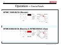
Operation -- Fascia Panels
WTMC 3300US/CN (Electric)
WTMC6300US/CN (Electric) & WTMC6500UC (Gas)
1st Edition/Revision 4 (1/19/04)
16
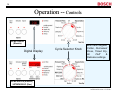
Operation -- Controls
WTMC3300US
(Electric)
Digital Display
Cycle Selector Knob
Both have Regular/
Cotton, Permanent
Press, Timed Dry,
Air
Fluff
&
Delicates settings.
WTMC6300US (Electric)
/ WTMC6500UC (Gas)
1st Edition/Revision 4 (1/19/04)
17
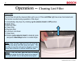
Operation -- Cleaning Lint Filter
Lint Filter
The lint filter should be cleaned after each use or if the Lint Filter light becomes illuminated and
the buzzer sounds during operation of the dryer:
1. Immediately stop dryer by rotating cycle selector knob to Off position.
2. Open door.
3. Remove filter.
4. Clean filter.
5. Replace filter.
6. Let dryer cool down.
7. Close door.
8. Rotate cycle selector knob to desired cycle
and press Start/Stop button to restart dryer.
HINT: If the “lint filter” light won’t turn off, clean the
lint filter (by hand) with dish soap and water. The
lint filter is very fine and can be clogged over time
when fabric softener or softener sheets are used.
NOTE: The “lint filter” light will turn on during
normal use when the lint filter needs to be cleaned.
The light will NOT turn on during the test program.
1st Edition/Revision 4 (1/19/04)
18
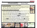
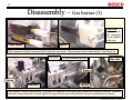
Disassembly -- Fascia Panel
To remove fascia panel to access control module:
Remove caps
• Disconnect electric power. Remove (4) T-20 Torx front/side screws and lift
panel up. Caps over screws can be removed using fingernails or a sharp
knife – take care to not scratch fascia panel or caps.
T-20 screws
To remove control module from fascia panel:
• For best results, start from the left and work progressively toward the right.
Module will be upside-down (due to wire harnesses).
• Using a small blade (calibrating) screwdriver, gently pry two (2) internal tabs,
starting from left to right. Don’t pry all two (2) internal tabs at once -- pry
outside tabs (top & bottom) & internal tabs together from left to right.
• Don’t force the module as you pry left to right. The module will come off
easily if removed properly, although it can be tricky. Plastic parts can break.
• The knob cannot be removed from the fascia panel – it does NOT need to be
removed to remove the control module. The module lifts away from the knob.
• Don’t break wire mounts holding wire harnesses to fascia panel – cut wire ties
holding harnesses to mounts. Bring replacement wire ties for reassembly.
Pry module tabs
Module
& panel
Module tabs
Cut wire ties
1st Edition/Revision 4 (1/19/04)
19
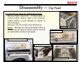
Disassembly -- Top Panel
To remove top panel for improved access:
• Remove fascia panel first. If fascia panel or
control module doesn’t need to be removed,
support panel to avoid damage to module or
wire harnesses.
• Remove T-20 Torx screws, then lift panel up.
• NOTE: Although the top panel doesn’t have to
be removed, its easy to remove and its removal
provides better access for all repairs.
T-20 screws
Control module details
Dryer with fascia panel unscrewed
Fascia panel side screw bushing
Dryer with top panel removed
1st Edition/Revision 4 (1/19/04)
20
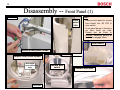
Disassembly -- Front Panel (1)
T-20 screws
Front
panel
tabs
HINT:
• Remove front panel to access
front shield, fan, R3 NTC &
door switch.
• Front panel hangs to frame by
six tabs, three per side.
Panels can be tricky to
reinstall, especially getting all
six tabs to engage frame.
Door switch
Remove front panel screws
Remove front shield screws
Don’t forget
screw behind
hinge
Remove door
switch
Remove door seal
T-20 screws
1st Edition/Revision 4 (1/19/04)
21
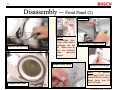
Disassembly -- Front Panel (2)
T-20 screws
Remove fan housing
NOTE:
Occasionally door
hinge white plastic
bushings can fall
off. Make sure all
four are collected
when
removing
hinges.
Remove door latch
Remove fan cover
Remove door hinge cover
Remove door hinge
HINT:
To remove
door, open it 180º (so it
doesn’t fall off), remove
hinge cover and lift
door off hinge.
1st Edition/Revision 4 (1/19/04)
22
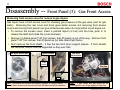
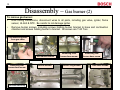
Disassembly -- Front Panel (3):
Gas Front Access
Removing front access cover for access to gas dryers:
Gas dryers have a front access cover for checking gas pressure at the gas valve (and for gas
leaks). Removing the rear cover and drum gives better access, but removing front access
covers and moving front panels can give limited access when its not practical to pull dryers out.
• To remove the access cover, insert a pointed object (or tool) into the hole, push in to
release the latch and rotate the cover clockwise.
• Remove (4) fascia panel T-20 Torx screws, then lift panel up out of the way. Remove front
panel T-20 Torx screws, then lift panel up (so tabs clear dryer frame).
• Don’t remove the front shield – it has the two front drum support wheels. If front shields
are removed, drums must be supported so they won’t fall.
Gas dryer access port
Gas dryer
front access
Typical access
T-20
screws
Gas tap
Tab
HINT: Gas valves and burners are attached together to a single bracket. To
remove them, screws must be removed from the base and burner chamber.
HINT: If gas valves and gas piping will be
disconnected, turn off gas supply to dryer first.
1st Edition/Revision 4 (1/19/04)
23
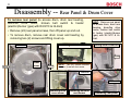
Disassembly -- Rear Panel & Drum Cover
To remove rear panel (to access drum, drum rear bearing,
drum/fan drive motor, broken belt switch & heater
(electric)/burner (gas) with R2 NTC & Hi-limit)
• Remove (22) rear panel screws, then lift panel up and out.
• To remove drum, remove rear drum cover and bearing by
removing two (2) screws and lifting cover up.
Removing two vent screws
T-20 screws
HINT: Remove rear panel
to access drum, drum rear
bearing, drum/fan drive
motor, broken belt switch
& heater (electric)/burner
(gas) with R2 NTC & Hilimit.
Lifting drum cover out
Screw
Screw
Drum
cover
Screw
NOTE: The (22) screws includes
the one (1) rear air duct screw.
T-20 screw
T-20 screws
Removing drum
cover screw
Removing exhaust
vent screw
Removing rear panel
1st Edition/Revision 4 (1/19/04)
24
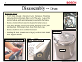
Disassembly -- Drum
Removing drum:
Belt
• If not done already, disconnect wire harnesses hindering
removing drum and place them out of the way. Leave the
control module (with wire harnesses) mounted to the frame.
Belt
• Remove terminal block (electric dryers) for better access.
• If not done already, remove rear panel and drum cover (with
rear bearing). Disconnect drum cover from duct area.
Removing belt
• Remove belt from drum and belt tensioner.
• Carefully lift drum (toward rear of dryer) out from front shield
drum support wheels.
Removing terminal block
Drum cover
Drum support wheel
Drum
1st Edition/Revision 4 (1/19/04)
25
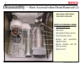
Disassembly – Parts Accessed when Drum Removed (1)
Gas dryer after drum
has been removed.
PARTS ACCESSIBLE WHEN
DRUM REMOVED:
• Gas valve
• Gas igniter & flame sensor
• Drum drive/fan motor
• Broken belt
tightener assy.
switch/belt
• Burner chamber with N2
NTC & Hi-limit
• Rear air duct
1st Edition/Revision 4 (1/19/04)
26
Disassembly – Parts Accessed when Drum Removed (2)
Electric dryer after
drum has been
removed.
PARTS ACCESSIBLE WHEN
DRUM REMOVED:
• Drum drive/fan motor
• Broken belt
tightener assy.
switch/belt
• Heater assy. with N2 NTC
& Hi-limit
• Rear air duct (removed from
this photo)
1st Edition/Revision 4 (1/19/04)
27
Disassembly -- Drum Drive Motor
To remove drum drive motor:
• Remove rear panel & rear air duct. Remove belt
from belt tensioner. Remove top panel & drum if
needed for better access.
• Disconnect terminal connector from motor, then
remove two screws from motor mount & one screw
holding fan to front shield. Lift rear of motor mount
up and slide entire assembly toward rear of dryer.
• While holding motor shaft, not rotor fins, remove
fan blade from motor shaft. Remove three screws,
then remove fan housing from motor.
• Remove spring clamps by pushing ends of them
down and away from motor. Lift motor up from
motor mount.
Use 1” socket wrench – turn
cw to loosen (left-hand thread)
Fan screw
Motor
mount
Fan screw
Mount tab
Belt
Drum drive motor
Belt
Spring clamp
Removing belt
Push down
on spring to
clear tab
Terminals
Spring clamp
Screw
Screw
Belt tensioner
Removing fan
Removing spring clamp
1st Edition/Revision 4 (1/19/04)
28
Disassembly – Electric heater
To remove electric heater:
•
Turn off or disconnect electric power.
•
After removing rear panel screws & one rear
duct screw, remove rear panel.
•
Remove four rear cover screws & two duct
screws, then lift rear cover with duct up and
away from heater assembly. Disconnect wires.
•
Slide heater toward rear of dryer until tabs
slide out of slots in dryer base.
Slide out
Heater
Removing
duct screws
Heater tabs
T-20 screws
NTC
Hi-limit
1st Edition/Revision 4 (1/19/04)
29
Disassembly – Gas burner (1)
To remove gas burner:
•
Turn off gas supply & unplug power cord.
•
After removing rear panel screws & one
rear duct screw, remove rear panel.
•
Remove four rear cover screws & two
duct screws, then lift rear cover with duct
up and away from burner assembly. If
needed for better access, remove drum.
•
Disconnect gas pipe & 90º elbow fitting
from gas valve.
T-20 screws
Removing 2
duct screws
Gas valve
Burner
Igniter
Gas
pipe
Use 1” open-end wrench
Disconnecting gas
line from gas valve
Hi-limit
Burner
chamber
Hi-limit
NTC
Flame
sensor
All screws T-20
1st Edition/Revision 4 (1/19/04)
30
Disassembly – Gas burner (2)
To remove gas burner:
•
After noting connections, disconnect wires to all parts, including gas valve, igniter, flame
sensor, Hi-limit & NTC. Be careful to not damage igniter.
•
Remove burner screws, including screws holding burner bracket to base and combustion
chamber and screws holding burner to bracket. All screws are T-20 Torx.
Disconnecting wires
from gas valve
Screw
Gas valve & burner
Removing front
burner base screw
Removing rear
burner base screw
All screws T-20
Removing rear
burner base screw
Burner screws
Burner ring screws
Gas valve screws
LP burner without ring
1st Edition/Revision 4 (1/19/04)
31
Disassembly – Gas burner (3)
CAUTION:
Igniters can
be damaged
if not handled
with care.
Igniter
Flame sensor
Flame sensors & igniters are each held in place by one screw. Flame sensors have a tab and slot – slide them up.
Gas valve
LP burner without burner ring
Gas valve
Burner
Gas tap
Gas valve
Bracket
Gas valves (3 screws) and burners (2 screws) are attached to the same gas valve/burner mounting bracket. Brackets
are held to dryer bases by 2 screws (@ front of gas valves & rear of burners) & to burner chambers by one screw.
1st Edition/Revision 4 (1/19/04)
32
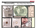
Disassembly -- Rear Main Drum Bearing
HINT: To remove
sleeve bearing
from rear of
drum (& rear
cover):
Rear cover
• Remove spring
clip positioning
drum shaft in
bearing.
Drum
Removing spring clip from drum shaft
• Remove bearing
housing
with
bearing
by
unscrewing four
(4) T-20 screws.
T-20 screws
1st Edition/Revision 4 (1/19/04)
33
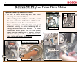
Reassembly -- Drum Drive Motor
Tips when installing drum drive motor:
• Lift rear of motor mount up and slide entire
assembly toward front of dryer.
• While holding motor shaft, not rotor fins, install
fan blade onto motor shaft. Since shaft has lefthanded thread, rotate fan counterclockwise.
• Make sure broken belt switch has been reset
whenever working on motor, replacing belt or
having removed drum for access. To reset
broken belt switch, push onto left side (black)
plastic plunger (viewing rear of motor). Plunger
will click when pushed. If switch hasn’t been
reset, motor and heater will not work.
Belt
Motor
mount
Fan screw
Belt
Mount tab
Installing belt
Use 1” socket wrench – turn
ccw to tighten (left-hand thread)
Fan screw
Terminals
Push left
plunger in to
reset switch
Screw
Screw
Belt tensioner
Installing fan
Resetting broken belt switch
1st Edition/Revision 4 (1/19/04)
34
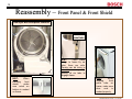
Reassembly – Front Panel & Front Shield
Gas dryer with front panel removed
Front
panel tabs
HINT:
Front panel
hangs to frame by six
tabs, three per side.
Panels can be tricky to
reinstall,
especially
getting all six tabs to
engage frame.
HINT:
When
installing
front
shield,
make
sure notch on
bottom is seated
on frame.
HINT:
When
aligning
front
panel tabs on
frame, make sure
door
seal
is
seated properly.
1st Edition/Revision 4 (1/19/04)
35
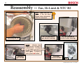
Reassembly -- Fan, Hi-Limit & NTC R2
HINT: Make sure fan is
tight. If fan nut won’t
tighten down adequately,
install a lockwasher.
NTC R2 (on side of
gas burner housing)
Tightening fan nut
NTC R2 (on side of
electric heater housing)
NOTE:
Hi-limits (high
temp cutouts), located on
heater/burner housings,
trip @ 347ºF (electric) or
347ºF (gas). To reset Hilimits, press red button.
Resetting
gas Hi-limit
Resetting
electric Hi-limit
Fan
1st Edition/Revision 4 (1/19/04)
36
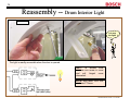
Reassembly -- Drum Interior Light
T-20 screw
I’ve seen
the light!
The light is readily accessible when the door is opened.
HINT: To access bulb,
unscrew one screw in cover
and
pull
hinged
cover
downward.
NOTE: Bulb rated 120V/10W
and uses C7 base.
1st Edition/Revision 4 (1/19/04)
37
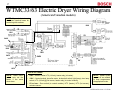
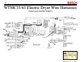
WTMC33/63 Electric Dryer Wiring Diagram
(American/Canadian models)
NOTE: Dryers don’t stack and
don’t have terminal boxes for
combining with washers.
120V
120V
5V
240V
5V
120V
120V
240V
240V
5V
120V
PARTS VOLTAGES:
NOTE: Motor cutout
switch cuts out the
heater if the motor
shuts down.
• 240V – Heater, heater HTC (Hi-limit), heater relay (to heater).
• 120V – Control module, drum/fan motor, broken belt switch, light (lamp), door lamp
switch, HTC (Hi-limit) @ lint screen, heater relay (to control module).
NOTE: Heater cycles
on and off as needed
to keep temperatures
at appropriate levels.
• 5V or less – Door switch (to control module), NTC (heater), NTC (lint screen),
moisture sensor.
1st Edition/Revision 4 (1/19/04)
38
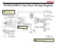
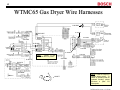
WTMC6500UC Gas Dryer Wiring Diagram
NOTE: Dryers don’t stack and
don’t have terminal boxes for
combining with washers.
HINT:
“Mains” is the
European term for “power”.
gas heater
NOTE: Burner cycles on and off as needed to keep
temperatures at appropriate levels.
1st Edition/Revision 4 (1/19/04)
39
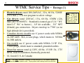
WTMC Service Tips – Ratings (1)
•
•
•
•
•
•
Electric dryers rated 208-240VAC, 22A, 60 Hz, 5280W
(22A max.). Use test program to select voltage.
Gas dryers rated 120VAC, 15A, 60 Hz, 1500W (12A
max.) & 18,500 BTU. Standard is natural gas (5-14 “ WC
inlet/3.5” WC to burner) – LP kit available. 3/8” NPT
(female) gas connection. Dryers rated up to 7700’ (so no
high altitude kit is provided).
Canadian electric models use 6’ power cords with NEMA
14-30P 240V, 30A, 4-wire plugs, which mates to NEMA
14-30R outlets.
Gas models use 6’ power cords with NEMA 5-15P 15A,
3-wire plugs, which mate to standard grounded outlets.
Drum/fan motors rated @ 120V, 60 Hz, 1/3 HP, 5A, 1725
RPM, class B insulation, thermally protected.
UL listed (U.S. & Canada)
HINT: Dryers can
be run on 240V or
208V.
To change
voltage from 240V to
208V, use voltage
changeover test (8th
position from right).
NOTE: The only difference between WTMC33/63US & CN electric dryers is
Canadian models have power cords. Drying cycles and heating levels are identical.
1st Edition/Revision 4 (1/19/04)
40
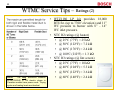
WTMC Service Tips – Ratings (2)
NOTE:
The only difference between
WTMC33/63US & CN electric dryers is
Canadian models have power cords. Drying
cycles and heating levels are identical.
• WTZ1180 LP kit provides 18,000
BTU/hr. (up to 7700’ elevation) and 11”
WC pressure to burner with 8” – 14”
WC inlet pressure.
• NTC R2 ratings (@ heater)
• @ 25ºC (77ºF) = 25 kΩ
• @ 50ºC (122ºF) = 7.2 kΩ
• @ 80ºC (176ºF) = 2.4 kΩ
• @ 100ºC (212ºF) = 1.3 kΩ
• NTC R3 ratings (@ lint screen)
• @ 25ºC (77ºF) = 10 kΩ
• @ 40ºC (104ºF) = 5.3 kΩ
• @ 50ºC (122ºF) = 3.6 kΩ
• @ 60ºC (140ºF) = 2.4 kΩ
1st Edition/Revision 4 (1/19/04)
41
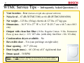
WTMC Service Tips – Infrequently Asked Questions (1)
•
•
•
•
•
•
•
•
Vent location – Rear (bottom or right side optional with kits)
Noise level – 67 dB (WTMC3300) or 66 dB (WTMC6300/6500)
Net weight – 125 lbs. (56 kg) electric & 127 lbs. (57 kg) gas
Dimensions – 36.9” H x 27” W x 31.6” D (93.7 cm x 68.7 cm x 80.3
cm)
Output with clean lint filter (18 lbs. Regular Cotton / 9 lbs. Permanent
Press @ max. duct) = 115/ 107 cfm. (with dirty lint filter = 86 / 83 cfm).
Condensation dryers available – No
Reversible door – Yes (can put hinge on right side)
Door opening – 19.7” (50 cm)
• Duct length (max.) – 66’ (20 m) of 4” rigid metal duct
• Drum speed – 50 RPM
NOTE: The only difference between WTMC33/63US & CN electric dryers is
Canadian models have power cords. Drying cycles and heating levels are identical.
1st Edition/Revision 4 (1/19/04)
42
WTMC Service Tips – Infrequently Asked Questions (2)
• Power outages – Dryers enter standby mode for power
interruptions over 10 minutes long.
• Door opened during cycle – Dryers can be restarted once
doors are closed.
• Sales demo mode – Available. Push and hold Start/Stop
& Delicates buttons, then rotate cycle selector knob to 40
minute timed dry (WTMC33) or Air Fluff (WTMC63/65).
Push Start/Stop button to enter or stop sales demo mode.
• Hi-limit temperature settings – B9 resettable type @
heater: 347ºF (175ºC) both electric & gas. B19 one-time
fuse @ lint screen (front shield): 194ºF (90ºC).
• Light bulb ratings – 120V, 10W, uses C7 base.
NOTE: The only difference between WTMC33/63US & CN electric dryers is
Canadian models have power cords. Drying cycles and heating levels are identical.
1st Edition/Revision 4 (1/19/04)
43
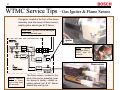
WTMC Service Tips – Drum/Fan Drive Motor
The main drive motor drives the drum & fan:
h Its connected in series to the heater/burner circuit
so the heater/burner are cut out if the motor fails.
h Its connected in series with the broken belt switch
& Hi-limit (@ lint screen) so the motor is cut out if
the belt breaks or the temperature at the front of
the dryer gets too high.
h If the heater/burner won’t work, check the motor
as well. Make sure the broken belt switch is reset.
h If the motor won’t work, check the lint screen &
duct for excessive lint, the belt/broken belt switch
& the motor. Make sure the broken belt switch is
reset.
Gas dryer wiring shown
Motor
circuit
Gas burner
circuit
Broken belt switch
HINT: Remove rear panel to access drum drive motor, belt/pulley & electric heater/gas burner.
HINT:
To reset the
broken belt switch,
push in the left black
plunger (viewing rear of
motor).
1st Edition/Revision 4 (1/19/04)
44
WTMC Service Tips – Electric Heater Assembly
Only 240V circuit in electric dryers is the heater circuit. It runs
through the motor, Hi-limit, heater & heater relay. The connection
through the motor cuts out the heater if the motor isn’t running.
240V heater circuit
HINT: If heater doesn’t work after
repairs have been made, check if
broken belt switch has been reset.
120V heater control circuit
Resetting Hi-Limit
HINT: Hi-Limit (safety cutout) trips @:
• 175ºC (347ºF) for electric
• 175ºC (347ºF) for gas
HINT: NTC R2 reads ~ 25 kΩ
@ room temperature.
NOTE: Heaters cycle on and off as
needed to keep temperatures at
appropriate levels.
1st Edition/Revision 4 (1/19/04)
45
WTMC Service Tips – Gas Burner Assembly (1)
HINT: NTC R2 reads ~ 25 kΩ @
room temperature.
HINT: Hi-Limit (safety cutout) trips @:
• 175ºC (347ºF) for electric
• 175ºC (347ºF) for gas
Like electric dryers, the gas dryer burner
circuit runs through the motor & Hi-limit.
The connection through the motor cuts out
the burner if the motor isn’t running.
NOTE: Burners cycle on and off
as needed to keep temperatures
at appropriate levels.
Gas valve
Igniter
Flame
sensor
Resetting Hi-Limit
1st Edition/Revision 4 (1/19/04)
46
WTMC Service Tips – Gas Burner Assembly (2)
LP burner without ring
Good flame – fan pulls air
through burner cavity and air flows
freely through burner air holes.
Flames are blue, compacted and
uniformly distributed – flames
have “roaring” sound.
Gas burner
Good flame
Natural gas burner
ring (not used for LP)
Poor flame – poor air flow through
burner (from blocked burner air
holes) causes a lazy, long and
quiet flame with some yellow.
Poor flame
NOTE: Burners cycle on and off
as needed to keep temperatures
at appropriate levels.
HINT: If burner doesn’t work after
repairs have been made, check if
broken belt switch has been reset.
For best results, fan
must be running and
burner air holes must
be clear.
HINT: For best
results, lint screen
should be clean
and fan be tight
onto motor shaft.
1st Edition/Revision 4 (1/19/04)
47
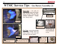
WTMC Service Tips – Gas Igniter & Flame Sensor
The igniter, located in the front of the burner
assembly (near the burner & flame sensor),
reliably ignites natural gas & LP flames.
CAUTION: Igniters can be damaged
if not handled with care.
Igniter
NOTE:
Igniters
glow and reach ~
2100ºF after 30
seconds.
Flame sensor
NOTE: Sensors
react to flame
out in less than
45 seconds.
The flame sensor, located in the
front of the burner assembly (near
the burner & igniter), reliably reignites natural gas & LP flames
should they ever go out.
1st Edition/Revision 4 (1/19/04)
48
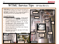
WTMC Service Tips – LP Gas Kit (1)
WTMC6500 gas dryers are set up from the factory for
natural gas (for elevations up to 7700’). Use LP gas kit
WTZ1280 (available from new equipment dealers) to
convert dryers to LP (for elevations up to 7700’).
Gas valve
Using WTZ1280 LP kit:
•
Follow kit instructions carefully. These general
guidelines don’t include the entire kit instructions.
•
LP manifold pressure will be 11” wc after the kit is
installed. Inlet pressure should be ~ 8” – 14” wc.
•
LP rating (up to 7700’ elevation) will be 18,000
BTU/hour after the kit has been installed.
•
Turn off gas supply & unplug power cord.
•
Remove rear panel & rear drum cover. Remove
drum (for better access).
•
Disconnect wire harness, gas pipe & 90º elbow
fitting from gas valve.
Burner
Igniter
Gas
pipe
Natural gas burner
ring (not used for LP)
Hi-limit
T-20 screws
Removing 2
duct screws
Use 1” open-end wrench
Disconnecting gas
line from gas valve
Burner
chamber
All screws T-20
Flame sensor
Flame
sensor
NOTE:
Igniters
glow and reach ~
2100ºF after 30
seconds.
1st Edition/Revision 4 (1/19/04)
49
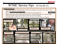
WTMC Service Tips – LP Gas Kit (2)
Using WTZ1280 LP kit:
•
After noting connections, disconnect wires to all parts, including gas valve, igniter, flame sensor, Hi-limit
& NTC. Be careful to not damage igniter.
All screws T-20
•
Remove burner, then remove burner ring from burner (as its not needed for LP).
•
Remove natural gas valve and replace with LP gas valve. Install LP rating plate and conversion labels.
•
Check gas pressure at gas valve and check for leaks, then check flame quality.
•
Keep natural gas valve & burner ring (with screws) in case dryer is converted back to natural gas.
Remove front access cover
Disconnect wires
from gas valve
Screw
Gas valve & burner
Removing rear
burner base screw
LP burner without ring
Remove burner from bracket
Remove front
burner base screw
Remove burner ring
Remove rear
burner base screw
Remove gas valve screws
Not needed for LP
1st Edition/Revision 4 (1/19/04)
50
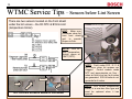
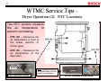
WTMC Service Tips – Sensors below Lint Screen
There are two sensors located on the front shield
under the lint screen – the R3 NTC & B19 Hi-limit
(temperature limiter).
HINT: Make sure
customers clean lint
from front shield
grid
to
provide
proper air flow.
NOTE: B19 Hilimit (temperature
limiter) opens at
194ºF (90ºC).
NOTE: Fault codes E:01, E:11 &
E:12 occur when lint screens are
clogged.
Control module reads
NTC and approximates air flow –
when air flow is too low, fault codes
are generated. B19 Hi-limits do not
generate fault codes.
Hi-limit
H
i-l
im
it
NTC
NT
C
NTC R3 & B19 Hi-limit in bottom of front shield
NOTE: B19 Hi-limit (temperature
limiter) is a one-time fuse type and
must be replaced when it has
opened.
1st Edition/Revision 4 (1/19/04)
51
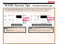
WTMC Service Tips – Wrinkle/Finished Light
If the wrinkle protect/finished light is on while the display is off, an internal switch (S3) on
the control board has been damaged and the entire control module has to be replaced.
WTMC3300 (Electric)
NOTE: Display being off:
• WTMC33 dryers – display is blank (LED
segments don’t show)
• WTMC63/65 dryers – red backlight will be off
WTMC6300 (Electric) / WTMC6500 (Gas)
NOTE: To confirm the control module has failed, rotate
the cycle selector knob to Off. If the wrinkle
protect/finished light stays on while the display stays
off, the module is damaged and must be replaced.
1st Edition/Revision 4 (1/19/04)
52
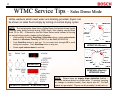
WTMC Service Tips – Sales Demo Mode
Unlike washers which need water and draining provided, dryers can
be shown on sales floors simply by turning on normal drying cycles.
NOTE: The test program does have a Sales Demo test which shows typical
displays seen during normal drying (LED’s flash, then display counts down
from :30 to :00). If desired to use this Sales Demo mode instead of turning
on normal drying cycles, please do the following:
•
While pushing & holding Start/Stop & Delicates buttons, rotate cycle selector
knob to to 40 minute Time Dry (WTMC33) or Air Fluff (WTMC63/65).
•
Push Start/Stop button to start test. Do not rotate knob through Off to avoid
exiting test program. Push Start/Stop button to stop test.
•
WTMC3300 (Electric)
Rotate cycle selector knob to end test.
WTMC3300
WTMC6300 (Electric) /
WTMC6500 (Gas)
WTMC6300 (Electric) / WTMC6500 (Gas)
NOTE: Dryers have an empty drum detection feature –
moisture sensors detect no clothes after 11 minutes (sensing
no change in moisture levels), then dryers shut off. No fault
codes are generated. Dryers can be promptly turned back on.
1st Edition/Revision 4 (1/19/04)
53
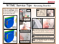
WTMC Service Tips – Reversing Door Kit
Using door hinge kit (sales
accessory) WTZ1260, doors
can be reversed to open on
the left side (hinge left).
T-20
screws
NOTE: Occasionally
door
hinge
white
plastic bushings can
fall off. Make sure all
four
are
collected
when removing hinges.
Change door
hinge cover
Hinge on
right side
Change door hinge
HINT: Kit includes instructions & all parts, including red
& white strips for door (showing door “handle” location”
& covers for unused openings. Remove red & white
strips (to exchange positions) by squeezing them from
behind.
HINT: To remove door, open it 180º (so it doesn’t fall
off), remove hinge cover and lift door off hinge.
Hinge on
left side
Change door latch
NOTE: Kit WTZ1260 can only be obtained
through new equipment dealers, not through
service parts distributors.
1st Edition/Revision 4 (1/19/04)
54
WTMC Service Tips -- Test Program (1): Selecting Tests
Selecting WTMC Dryer Tests
Test
Position on knob
WTMC33
WTMC63/65
View fault codes
Safety test
Display test (LED's/LCD's)
Control elements test
Consumer test
Moisture sensor resistance measurement
Sales demo program
240V:208V changeover
Automatic end-of-tape program
1st position on right (cw)
2nd position on right (cw)
3rd position on right (cw)
4th position on right (cw)
5th position on right (cw)
6th position on right (cw)
7th position on right (cw)
8th position on right (cw)
1st position on left (ccw)
Extra Dry (Reg./Cot.)
Very Dry (Reg./Cot.)
Regular Dry (Reg./Cot.)
Damp Dry (Reg./Cot.)
Air Fluff
20 min. Time Dry
40 min. Time Dry
60 min. Time Dry
Very Dry (Perm. Press)
Extra Dry (Reg./Cot.)
Very Dry (Reg./Cot.)
Regular Dry (Reg./Cot.)
Damp Dry (Reg./Cot.)
Very Dry (Mix)
Regular Dry (Mix)
Air Fluff
Medium Time Dry
Very Dry (Perm. Press)
HINT: Electric dryers can be run
on 240V or 208V. To change
voltage from 240V to 208V, use
voltage changeover test (8th
position from right).
HINT: To run dryers in sales
demo mode, use sales demo
program (7th position from right).
WTMC3300
(Electric)
WTMC6300 (Electric) /
WTMC6500 (Gas)
ENTERING TEST PROGRAM:
While
pushing
&
holding
Start/Stop & Delicates buttons,
rotate cycle selector knob to
desired position above.
1st Edition/Revision 4 (1/19/04)
55
WTMC Service Tips -- Test Program (2): Starting
To enter/exit test program for WTMC dryers:
¨
¨
¨
Rotate cycle selector knob to Off position.
Push and hold Start/Stop and Delicates buttons at the same time, then turn dryer on by rotating cycle selector knob
either direction -- keep holding Start/Stop and Delicates buttons until Start/Stop light flashes rapidly. Dryer is now in
the test program.
When test program has been entered:
¨
Start/Stop light flashes rapidly.
¨
Select individual parts to test by rotating cycle selector knob as shown on previous page.
¨
Once test has been selected, start test by pushing Start/Stop button. Start/Stop light will stay on continually
while tests are running. Push Start/Stop button again to end any test – rotating cycle selector knob stops all
tests except Control Elements test. Tests have finished once Start/Stop light flashes rapidly again.
¨
To exit test program, rotate cycle selector knob to Off position.
HINT: Electric dryers
can be run on 240V or
208V.
To change
voltage from 240V to
208V,
use
voltage
changeover test (8th
position from right).
WTMC6300 (Electric) / WTMC6500 (Gas)
HINT: To run dryers in
sales demo mode, use
sales demo program
(7th position from right).
NOTE: When test program is initially entered, last fault code
will show. Display will be cleared once any test is started.
1st Edition/Revision 4 (1/19/04)
56
WTMC Service Tips -- Test Program (3): Displays
WTMC Dryer Test Program Displays
Test
Knob Position
WTMC33
WTMC63/65
1st position on See fault codes (4)
right (cw)
Safety test
2nd position on
right (cw)
Display test
(LED's/LCD's)
3rd position on All lights/display digits turn All lights/display digits turn Tests if (LCD) text displays & (LED)
on, then cycles through lights. on, then cycles through lights. lights/displays work OK.
right (cw)
Control
elements test
4th position on
right (cw)
Consumer test
5th position on Fan runs & display counts Fan runs & display counts Turns heater & motor on so current can
from :01 - :04 , then test ends. from :01 - :04 , then test ends. be measured. Motor runs during steps
right (cw)
:02 - :04 , while heater runs only during
step :03 .
Moisture sensor 6th position on Drying & Start/Stop lights
on when drum empty.
resistance
right (cw)
measurement
Sales demo
program
7th position
right (cw)
240V:208V
changeover
8th position on 240V or 208V on display
right (cw)
See fault codes (4)
Notes
View fault
codes
Run this test every time.
Not for U.S. -- for testing for power in
circuits with neutral. Runs drum motor
& applies power to one side of heater.
Tests cycle selector knob and
pushbuttons. Can't end test using
cycle selector knob , only by
Start/Stop button.
Drying & Start/Stop lights
on when drum empty.
Designed for using with variable
resistance board, but can test with fixed
resistances.
on LED's flash, then display LED's flash, then display Simulates typical displays during normal
counts down from :30 - :00 -- counts down from :30 - :00 -- drying. Program runs 82 seconds (1
test repeats itself.
test repeats itself.
minute, 22 seconds), then repeats.
240V or 208V on display
Push Delicates button to change
voltage -- display flashes when voltage
changed. Appears on gas dryers, but
isn't used.
Automatic end-of- 1st position on left Finished light flashes -- can't Finished light flashes -- can't Only for production -- do not use.
tape program
(ccw)
exit test ; must turn dryer off exit test ; must turn dryer off
to exit test program.
to exit test program.
1st Edition/Revision 4 (1/19/04)
57
WTMC Service Tips -- Test Program (4A): Fault Codes
WTMC Dryer Test Program Fault Codes
Fault
Code
Fault
Solution
Notes
Effect
E:11
Overheating due
clogged lint filter.
to Clean lint filter (& air duct if necessary). Displays E:01 during normal use.
Measures reduced air flow.
E:12
Severe overheating due Clean lint filter (& air duct if necessary). Displays E:01 during normal use.
to clogged lint filter.
Measures reduced air flow.
E:13
Maximum drying time Check heater, control module, NTC's & Stops & displays E:03 during
exceeded
Hi-limit's. Usually faulty heater. Can normal use (after maximum
also be overloaded dryer.
drying time limit of 240 minutes).
E:17
NTC error (NTC R3 @ Check NTC R3 &
lint screen)
Replace faulty part.
wire
harness. Typically shorted or opened wire Dryer stops & can't
harness.
be restarted.
E:18
NTC error (NTC R2 @ Check NTC R2 &
heater)
Replace faulty part.
wire
harness. Typically shorted or opened wire Dryer stops & can't
harness.
be restarted.
E:20
EEPROM error
Replace faulty control module.
Dryer stops & can't
be restarted.
E:21
Incorrect checksum
Replace faulty control module.
Dryer stops & can't
be restarted.
E:22
Invalid update
Replace faulty control module.
Dryer stops & can't
be restarted.
NOTE: To run fault codes test to display fault codes:
•
While pushing & holding Start/Stop & Delicates buttons, rotate cycle selector knob to Extra Dry – Regular/Cotton.
•
Push Start/Stop button to start test. Push Start/Stop button to scroll through fault codes (if more than one exist). Do
not rotate knob through Off to avoid exiting test program.
•
Rotate cycle selector knob to end test.
1st Edition/Revision 4 (1/19/04)
58
WTMC Service Tips -- Test Program (4B): Fault Codes
WTMC Dryer Test Program Fault Codes
Fault
Code
Fault
Solution
Notes
Effect
E:23
Model variant doesn't Replace faulty control module.
match table
Dryer stops & can't
be restarted.
E:24
Software
version Replace faulty control module.
doesn't match table
Dryer stops & can't
be restarted.
E:25
Damaged data table
Replace faulty control module.
Dryer stops & can't
be restarted.
E:26
Control error
Replace faulty control module.
NOTE: Fault displayed alternates with # of times fault occurred
every two (2) seconds. If there’s no faults, displays will be blank.
•
E:xx = fault code from E11 – E39 (e.g. E:11)
•
C:xx = # of occurrences (e.g. C:01)
NOTE: When test program is initially
entered, last fault code will show. Display
will be cleared once any test is started.
1st Edition/Revision 4 (1/19/04)
59
WTMC Service Tips -- Test Program (5): Controls
NOTE: To run control elements test to check buttons and knob:
•
While pushing & holding Start/Stop & Delicates buttons, rotate cycle selector knob to
Damp Dry – Regular/Cotton.
•
Push Start/Stop button to start test. Push buttons one at a time to check button
operation – when each button is pushed, its light will come on. Rotate cycle selector
knob through all positions to check knob operation (see chart below). Do not rotate knob
through Off to avoid exiting test program.
•
Push Start/Stop button to end test.
WTMC33 Knob
Extra Dry (Reg./Cot.)
Very Dry (Reg./Cot.)
Regular Dry (Reg./Cot.)
Damp Dry (Reg./Cot.)
Air Fluff
20 Minute Time Dry
40 Minute Time Dry
60 Minute Time Dry
Damp Dry (Perm. Press)
Regular Dry (Perm. Press)
Very Dry (Perm. Press)
NOTE: Lint filter light
doesn’t come on.
WTMC63/65 Knob
Extra Dry (Reg./Cot.)
Very Dry (Reg./Cot.)
Regular Dry (Reg./Cot.)
Damp Dry (Reg./Cot.)
Very Dry (Mix)
Regular Dry (Mix)
Air Fluff
Medium Time Dry
High Time Dry
Short
Wool Care
Heavy Load
Damp Dry (Perm. Press)
Regular Dry (Perm. Press)
Very Dry (Perm. Press)
WTMC3300
Lights
WTMC3300 (Electric)
Drying
Drying
Drying
Drying
Damp Dry
Damp Dry
Regular Dry
Regular Dry
Damp Dry Regular Dry
Damp Dry Regular Dry
Drying
Drying
Drying
Drying
Damp Dry
Damp Dry
Regular Dry
Regular Dry
Damp Dry Regular Dry
Damp Dry Regular Dry
Finished
Finished
Finished
Finished
Finished
Finished
Finished
Finished
WTMC6300 (Electric) /
WTMC6500 (Gas)
WTMC6300
(Electric) /
WTMC6500 (Gas)
1st Edition/Revision 4 (1/19/04)
60
WTMC Service Tips -- Test Program (6): Amp Draw
NOTE: To run consumer test to measure heater and motor current:
•
Disconnect electric power. Remove rear cover, making sure no electrical shorts
or shock will occur (once power is reconnected).
•
Locate motor & heater wire harnesses and place current clamp of meter around
harness to be measured. Reconnect electric power.
•
While pushing & holding Start/Stop & Delicates buttons, rotate cycle selector
knob to Air Fluff (WTMC33) or Very Dry – Mix (WTMC63/65).
•
Push Start/Stop button to start test. Measure motor current when display shows
:02, :03 or :04 and measure heater current when display shows :03.
•
Push Start/Stop button or rotate cycle selector knob to any position to end test.
Motor
NOTE: For consumer test, heater and motor run as follows:
:01 = both off (5 seconds).
:02 = motor on/heater off (10 seconds)
:03 = both on (60 seconds)
:04 = motor on/heater off (30 seconds)
Can only measure heater current during step :03.
Heater
Electric heater
Motor
Heater
HINT: Choosing wires to measure
current from:
Motor
•
Motor
•
Heater
Drum motor = either wire to
terminal 4 or 5 on motor.
Heater = either red wire to heater
(optional: can measure wire to
either terminal 1 or 2 on motor).
1st Edition/Revision 4 (1/19/04)
61
WTMC Service Tips -- Test Program (7): Moisture
Sensor Conductance
NOTE: To run sensor moisture conductance test:
•
Disconnect electric power. Remove rear cover, making sure no electrical shorts or shock will occur (once power is
reconnected). If necessary for access, remove drum.
•
Locate moisture sensor at front of dryer. Reconnect electric power.
•
While pushing & holding Start/Stop & Delicates buttons, rotate cycle selector knob to 20 minute Time Dry (WTMC33)
or Regular Dry – Mix (WTMC63/65).
•
Push Start/Stop button to start test. Control module measures resistance and lights come on to show test results as
shown in the table below.
•
Push Start/Stop button or rotate cycle selector knob to any position to end test.
Test
Drying Light Damp Dry Light
Drum empty -- conductance
electrodes open
Interrupting conductance
electrodes with a hand or
resistance (~ 100k Ω - 1 MΩ )
Shorting conductance
electrodes
Off
Drying
Off
Drying
Off
Off
Drying
Off
WTMC3300
Off
Off
Damp Dry
Off
Off
Damp Dry
Off
Off
Damp Dry
Faults Shown
Circuit shunted.
None
Short or shunted circuit.
None
Interruption or resistance too high.
Short or shunted circuit.
Interruption or resistance too high.
Interruption or resistance too high.
None
Resistance Range
>7.5 MΩ
<33.9 k Ω
>7.5 MΩ
<33.9 k Ω
>7.5 MΩ
<33.9 k Ω
WTMC6300
(Electric) /
WTMC6500 (Gas)
1st Edition/Revision 4 (1/19/04)
62
WTMC Service Tips -- Test Program (8): Changing
WTMC33/63 Electric Dryer Voltage
NOTE: To check or change WTMC33/63 electric dryer voltage (from 240V to 208V):
•
While pushing & holding Start/Stop & Delicates buttons, rotate cycle selector knob to
60 minute Time Dry (WTMC33) or Medium Time Dry (WTMC63).
•
Push Start/Stop button to start test.
•
Push Delicates button to change voltage (from 240V to 208V or from 208V to 240V).
•
Push Start/Stop button or rotate cycle selector knob to Off to end test & store voltage
setting.
1st Edition/Revision 4 (1/19/04)
63
WTMC Service Tips -- Troubleshooting of
Minor Faults (Customer Self-Help 1)
SELF-HELP
Dryers may exhibit problems unrelated to a malfunction of the dryer itself. The following table contains questions customers can
deal with without calling a serviceman.
Lint filters, exhaust ducts and moisture sensors should be cleaned according to the Cleaning and Care section in the Operating,
Care and Installation Instructions.
PROBLEM
POSSIBLE CAUSE
Start/Stop Indicator light doesn’t come on.
• The cycle selector knob hasn’t been rotated from Off position.
• A fuse may have blown or a circuit breaker tripped. Replace fuse or reset
circuit breaker at your fuse box/breaker box.
• The plug is not correctly or only loosely inserted into the receptacle.
Dryer doesn’t start.
•
•
•
•
•
Cycle is interrupted and Lint Filter light is
illuminated and buzzer sounds.
•
Cycle is interrupted, buzzer sounds, one or
several cycle indicators are flashing.
Drying level not reached or drying time too
long.
Cycle has not been selected.
“Start/Stop” button hasn’t been depressed.
Door isn’t closed properly.
Room temperature is below 32 °F (0 °C)
If necessary, switch the dryer off and wait 5 seconds before switching it on
again. Select the cycle again and press Start/Stop button.
Clean lint filter. If needed (when fabric softener has been used), wash gently
with dish soap and water.
• Check exhaust vent to see if it is blocked or too long.
Indicates faulty operation:
• Clean the lint filter and check the exhaust duct length.
• Switch the dryer off, wait for it to cool down and then restart.
•
•
Clean moisture sensor.
If there is a power failure for an extended period (> 10 minutes), the cycle
must be restarted.
1st Edition/Revision 4 (1/19/04)
64
WTMC Service Tips -- Troubleshooting of
Minor Faults (Customer Self-Help 2)
PROBLEM
POSSIBLE CAUSE
The laundry is not dry even though the highest
drying level has been selected.
• The drum is too full.
• The laundry was too wet when placed in the dryer.
• The room is not adequately ventilated. Make sure there is an
adequate supply of fresh air.
• The lint filter is blocked and should be cleaned.
• The exhaust vent is blocked or too long.
• Cycle selector knob hasn’t been rotated from the Off position.
• Bulb has failed. For safety reasons the bulb must only be replaced
by an authorized service agent.
Drum light does not work
1st Edition/Revision 4 (1/19/04)
65
WTMC Service Tips -Dryer Operation (1): Moisture Sensing
The control module continually measures the conductivity of wet
clothing (by measuring the voltage between the two sensors).
When the voltage
matches the one
required by the
customer dryness
setting, the dryer
stops.
NOTE: Dryers have an empty drum detection feature
– moisture sensors detect no clothes after 11 minutes
(sensing no change in moisture levels), then dryers shut
off. No fault codes are generated. Dryers can be
promptly turned back on.
The new moisture sensor is
located next to the lint screen
and does not need any sliding
contacts (brushes).
1st Edition/Revision 4 (1/19/04)
66
WTMC Service Tips -Dryer Operation (2): NTC Locations
Two NTC sensors measure
the air temperature to
prevent overheating.
• NTC R2 -- Measures the
air temperature in front of
the heater (electric) or
burner (gas).
• NTC R3 -- Measures the
air temperature at the
dryer door.
NTC R2
HINT: Keeping lint filter &
vent hoses clean of lint will
prevent most problems.
Rear of gas burner housing
NTC R3 in bottom of front shield
1st Edition/Revision 4 (1/19/04)
67
WTMC33/63 Electric Dryer Wire Harnesses
(American/Canadian models)
# 421665
120V
# 421669
# 421697
# 421681
120V
# 421685
# 421677
5V
# 421662
# 421596
240V
# 421664
5V
# 421678
# 421669
# 421680
120V
# 421673
# 421626
120V
# 421660
240V
# 421658
# 421663
# 421679
# 421664
240V
# 421681
5V
120V
NOTE: Parts are subject to
change without notice. To
obtain an updated parts list
(updated monthly), please
purchase a parts CD
subscription.
1st Edition/Revision 4 (1/19/04)
68
WTMC65 Gas Dryer Wire Harnesses
# 421665
# 421669
# 421597
# 421665
# 421685
# 421662
# 421596
# 421669
# 421678
# 421680
# 421626
# 421668
# 421663
# 421679
HINT:
“Mains” is the
European term for “power”.
# 421683
# 421675
# 421631
# 421631
gas heater
# 436477
NOTE: Parts are subject to
change without notice. To
obtain an updated parts list
(updated monthly), please
purchase a parts CD
subscription.
1st Edition/Revision 4 (1/19/04)