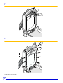
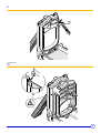
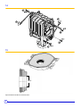
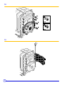
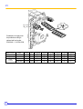
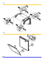
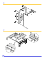
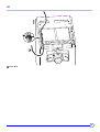
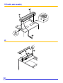
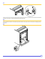
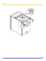
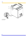
1
GT 300 A/II
English
Oil-Gas Fired Hot Water boiler
03/14/08
Please Read & Save
these instructions for
Future Reference
Installation and operating instructions
Warning:
Before putting the boiler into operation read this manual
carefully.
Warning:
The operating manual is part of the documentation that is
delivered to the installation’s operator. Go through the
information in this manual with the owner/operator and
make sure that he or she is familiar with all the necessary
operating instructions.
94863873
Notice:
This manual must be retained for future reference. Improper
installation, adjustment, alteration, service or maintenance can
cause injury, loss of life or property damage. Refer to this
manual. For assistance or additional information consult a
qualified installer, service agency or the gas supplier.
Guideline of Notices
Warning:
indicates presence of hazards that can cause, if not
avoided, severe personal injury, death or substantial
property damage.
!
Caution:
indicates presence of hazards that will or can cause, if not
avoided, minor personal injury or property damage.
Notice:
Application comment for optimum use of equipment and
adjustment as well as useful information.
Safety Considerations
Please observe the following safety instructions.
Read this manual carefully.
Correct installation and adjustment of the burner and the control
panel is a precondition for safe, efficient operation of the gas boiler.
Read this manual and the specifications on the safety label carefully
before attempting to put the burner into operation.
not store or use gasoline or other flammable liquids in
Do
the vicinity of this or any other appliance.
Installation and service must be peformed by a qualified
installer, service agency or the gas supplier.
ZReference to an other instruction book.
WHAT TO DO IF YOU SMELL GAS:
- Do not try to light any appliance.
- Do not touch any electric switch, do not use any phone in
your building.
- Immediately call your gas supplier from a neighbor’s
phone. Follow the gas supplier’s instructions.
- If you cannot reach your gas supplier, call the Fire
Department.
Observe the following symbols
DANGER
due to explosion of gas.
- Work only on gas components when you have a license to do so.
- Note that the assembly of gas and vent connections, the initial
start-up, the electrical connections, the maintenance and service
can only be performed by a licensed service contractor or
technician.
DANGER
due to electricity.
Warning:
Improper installation, adjustment, and/or operation could
cause carbon monoxide poisoning resulting in injury or
death.
This product must be installed and serviced by a
professional service technician who is experienced and
qualified in hot water boiler installation and gas
combustion.
- Prior to doing any work on the heating system, disconnect all
electrical power to the boiler at the emergency switch.
- It is NOT sufficient to shut off only the boiler control!
!
CAUTION!
SYSTEM DAMAGE
due to improper installation.
- Observe local and state codes as well as common industry
practices during the installation and operation of the heating
appliance.
!
CAUTION!
SYSTEM DAMAGE
due to inadequate cleaning and maintenance.
- A boiler cleaning and maintenance should be performed annually.
Verify complete system operation at the same time.
- Correct the problem immediately to prevent damage to the
system!
!
Caution: Strict compliance with these instructions is a
precondition for the correct operation of the boiler.
!
IMPORTANT
Service on this boiler should be undertaken only by trained and
skilled personnel.
Keep boiler area clear and free from combustible materials,
gasoline and other flammable vapors and liquids.
Do not place any obstruction in the boiler room that will hinder
the flow of combustion and ventilating air.
Read these instructions carefully before proceeding with the
installation of boiler. Post instructions near boiler for reference
by owner and serviceman.
Maintain instructions in legible condition.
"All installations of this appliance must be be in accordance to all national and local codes and
authorities having jurisdiction"
[Canadian Installation] CSA B139 for Oil & CSA B149 for Gas
[USA Installations] NFPA 54/ANSI Z223.1 for Gas & NFPA 31 for Oil
This boiler must be connected to a venting that will safely and effectively discharge all flue
gases to the outside in an effective manner.
Never burner garbage or paper in the unit, and never leave combustible materials around it.
Do not use gasoline, crankcase draining, or any other oil containing gasoline
2
GT 300 A/II
06/10/06 - 94863873 - 85534150E
Contents
Contents . . . . . . . . . . . . . . . . . . . . . . . . . . . . . . . . . . . . . . . . . . . . . . . . . . . . . . . . . . . . . . . . . . . . . . . . . . . . . . . . . . . .3
Regulations and guidelines . . . . . . . . . . . . . . . . . . . . . . . . . . . . . . . . . . . . . . . . . . . . . . . . . . . . . . . . . . . . . . . . . . . .4
Installation codes. . . . . . . . . . . . . . . . . . . . . . . . . . . . . . . . . . . . . . . . . . . . . . . . . . . . . . . . . . . . . . . . . . . . . . . . . . . . .4
General . . . . . . . . . . . . . . . . . . . . . . . . . . . . . . . . . . . . . . . . . . . . . . . . . . . . . . . . . . . . . . . . . . . . . . . . . . . . . . . . . . . . .4
1
2
3
4
Uncrating . . . . . . . . . . . . . . . . . . . . . . . . . . . . . . . . . . . . . . . . . . . . . . . . . . . . . . . . . . . . . . . . . . . . . . . . . . . . . . . . . . . . . . . . . . . . . . . .4
Packing. . . . . . . . . . . . . . . . . . . . . . . . . . . . . . . . . . . . . . . . . . . . . . . . . . . . . . . . . . . . . . . . . . . . . . . . . . . . . . . . . . . . . . . . . . . . . . . . . .4
Technical specifications of boilers . . . . . . . . . . . . . . . . . . . . . . . . . . . . . . . . . . . . . . . . . . . . . . . . . . . . . . . . . . . . . . . . . . . . . . . . . . . . .5
Main Dimensions . . . . . . . . . . . . . . . . . . . . . . . . . . . . . . . . . . . . . . . . . . . . . . . . . . . . . . . . . . . . . . . . . . . . . . . . . . . . . . . . . . . . . . . . . .6
Boiler Installation. . . . . . . . . . . . . . . . . . . . . . . . . . . . . . . . . . . . . . . . . . . . . . . . . . . . . . . . . . . . . . . . . . . . . . . . . . . . .7
1 Installation . . . . . . . . . . . . . . . . . . . . . . . . . . . . . . . . . . . . . . . . . . . . . . . . . . . . . . . . . . . . . . . . . . . . . . . . . . . . . . . . . . . . . . . . . . . . . . .7
2 Ventilation. . . . . . . . . . . . . . . . . . . . . . . . . . . . . . . . . . . . . . . . . . . . . . . . . . . . . . . . . . . . . . . . . . . . . . . . . . . . . . . . . . . . . . . . . . . . . . . .7
3 Assembly . . . . . . . . . . . . . . . . . . . . . . . . . . . . . . . . . . . . . . . . . . . . . . . . . . . . . . . . . . . . . . . . . . . . . . . . . . . . . . . . . . . . . . . . . . . . . . . .7
Piping . . . . . . . . . . . . . . . . . . . . . . . . . . . . . . . . . . . . . . . . . . . . . . . . . . . . . . . . . . . . . . . . . . . . . . . . . . . . . . . . . . . . . .8
1
2
3
4
Dimensional information required. . . . . . . . . . . . . . . . . . . . . . . . . . . . . . . . . . . . . . . . . . . . . . . . . . . . . . . . . . . . . . . . . . . . . . . . . . . . . .8
Recommendations . . . . . . . . . . . . . . . . . . . . . . . . . . . . . . . . . . . . . . . . . . . . . . . . . . . . . . . . . . . . . . . . . . . . . . . . . . . . . . . . . . . . . . . . .8
Filling . . . . . . . . . . . . . . . . . . . . . . . . . . . . . . . . . . . . . . . . . . . . . . . . . . . . . . . . . . . . . . . . . . . . . . . . . . . . . . . . . . . . . . . . . . . . . . . . . . .8
Ancillaries . . . . . . . . . . . . . . . . . . . . . . . . . . . . . . . . . . . . . . . . . . . . . . . . . . . . . . . . . . . . . . . . . . . . . . . . . . . . . . . . . . . . . . . . . . . . . . . .9
Combustion and ventilation . . . . . . . . . . . . . . . . . . . . . . . . . . . . . . . . . . . . . . . . . . . . . . . . . . . . . . . . . . . . . . . . . . .10
1 Clearances . . . . . . . . . . . . . . . . . . . . . . . . . . . . . . . . . . . . . . . . . . . . . . . . . . . . . . . . . . . . . . . . . . . . . . . . . . . . . . . . . . . . . . . . . . . . . .10
2 Replacement procedures . . . . . . . . . . . . . . . . . . . . . . . . . . . . . . . . . . . . . . . . . . . . . . . . . . . . . . . . . . . . . . . . . . . . . . . . . . . . . . . . . . .11
3 Dimensional information required for connection of the boiler . . . . . . . . . . . . . . . . . . . . . . . . . . . . . . . . . . . . . . . . . . . . . . . . . . . . . . .12
Oil or gas connections . . . . . . . . . . . . . . . . . . . . . . . . . . . . . . . . . . . . . . . . . . . . . . . . . . . . . . . . . . . . . . . . . . . . . . .12
1 Specific technical information supplied with the burner . . . . . . . . . . . . . . . . . . . . . . . . . . . . . . . . . . . . . . . . . . . . . . . . . . . . . . . . . . . .12
Electrical . . . . . . . . . . . . . . . . . . . . . . . . . . . . . . . . . . . . . . . . . . . . . . . . . . . . . . . . . . . . . . . . . . . . . . . . . . . . . . . . . . .13
1 Wiring . . . . . . . . . . . . . . . . . . . . . . . . . . . . . . . . . . . . . . . . . . . . . . . . . . . . . . . . . . . . . . . . . . . . . . . . . . . . . . . . . . . . . . . . . . . . . . . . . .13
2 Wiring procedure . . . . . . . . . . . . . . . . . . . . . . . . . . . . . . . . . . . . . . . . . . . . . . . . . . . . . . . . . . . . . . . . . . . . . . . . . . . . . . . . . . . . . . . . .13
3 Wiring boiler panel . . . . . . . . . . . . . . . . . . . . . . . . . . . . . . . . . . . . . . . . . . . . . . . . . . . . . . . . . . . . . . . . . . . . . . . . . . . . . . . . . . . . . . . .14
Start up procedures. . . . . . . . . . . . . . . . . . . . . . . . . . . . . . . . . . . . . . . . . . . . . . . . . . . . . . . . . . . . . . . . . . . . . . . . . .15
1 Start up procedures . . . . . . . . . . . . . . . . . . . . . . . . . . . . . . . . . . . . . . . . . . . . . . . . . . . . . . . . . . . . . . . . . . . . . . . . . . . . . . . . . . . . . . .16
2 Shut-down procedures . . . . . . . . . . . . . . . . . . . . . . . . . . . . . . . . . . . . . . . . . . . . . . . . . . . . . . . . . . . . . . . . . . . . . . . . . . . . . . . . . . . . .16
Maintenance . . . . . . . . . . . . . . . . . . . . . . . . . . . . . . . . . . . . . . . . . . . . . . . . . . . . . . . . . . . . . . . . . . . . . . . . . . . . . . . .17
1 Boiler . . . . . . . . . . . . . . . . . . . . . . . . . . . . . . . . . . . . . . . . . . . . . . . . . . . . . . . . . . . . . . . . . . . . . . . . . . . . . . . . . . . . . . . . . . . . . . . . . .17
Service and maintenance schedule . . . . . . . . . . . . . . . . . . . . . . . . . . . . . . . . . . . . . . . . . . . . . . . . . . . . . . . . . . . . .19
Spare parts - GT 300 A/II . . . . . . . . . . . . . . . . . . . . . . . . . . . . . . . . . . . . . . . . . . . . . . . . . . . . . . . . . . . . . . . . . . . . . .20
06/10/06 - 94863873 - 85534150E
GT 300 A/II
3
Regulations and guidelines
The installation and operating instructions shown here are given as a
guide for installation and operation and are not meant to replace any
State or Local Codes that may apply to the individual installation.
Good engineering practice should be used. Any deviation from laws
or regulations or industry Code or these instructions will void the
boiler warranty and any other responsability or liability of the De
Dietrich Thermiques S.A.
Only a qualified and licenced heating professional is to carry out the
removal, installation, startup and maintenance of this boiler. The boiler must
be installed according to all national and local codes having jurisdiction. The
operation of the boiler must be verified and all safety controls checked. Any
defect or abnormal operations must be corrected immediately. The entire
system requires annual service and cleaning at least once a year.
Installation codes
• THE BOILER SHALL BE ASSEMBLED AND INSTALLED BY A
QUALIFIED PROFESSIONAL ONLY. STRICT COMPLIANCE WITH
THESE INSTALLATION AND OPERATING INSTRUCTIONS IS A
PRECONDITION FOR THE CORRECT AND GUARANTEE OF THE
BOILER.
• THE INSTALLATION MUST CONFORM TO THE
REQUIREMENTS OF THE AUTHORITY HAVING JURISTRICTION
OR, IN THE ABSENCE OF SUCH REQUIREMENTS, TO THE CAN/
CGA B-149 FUEL GAS INSTALLATION CODES AND CSA B-139
OIL INSTALLATION CODES.
• WHERE REQUIRED BY THE AUTHORITY HAVING
JURISTRICTION, THE INSTALLATION MUST CONFORM TO THE
STANDARD FOR CONTROLS AND SAFETY DEVICES FOR
AUTOMATICALLY FIRED BOILERS ANSI/ASME CSD-1.
• THE INSTALLATION OF THE RELIEF VALVE SHALL BE
CONSISTENT WITH ANSI/ASME BOILER PRESSURE VESSEL
CODE, SECTION IV CSA B51.
• THE BOILER MUST NOT BE INSTALLED ON CARPETING.
• IF AN EXTERNAL ELECTRICAL SOURCE IS UTILIZED, THE
BOILER WHEN INSTALLED, MUST BE ELECTRICALLY BONDED
TO GROUND IN ACCORDANCE WITH THE REQUIREMENTS OF
THE AUTHORITY HAVING JURISTRICTION OR, IN THE
ABSENCE OF SUCH REQUIREMENTS, WITH THE CANADIAN
ELECTRICAL CODE PART 1, CSA C22.1, ELECTRICAL CODE.
ALL WIRES PRIOR TO DISCONNECTION WHEN
LABEL
SERVICING CONTROLS. WIRING CAN CAUSE IMPROPER
OPERATION AFTER SERVICINGS. “VERIFY PROPER
OPERATION AFTER SERVICE”.
General
The GT300 A/II are series of oil or gas fired, cast iron, automatic
boilers.
1 Uncrating
Upon arrival, check shipment to ensure all parts have been shipped.
Inspect all items for delivery damage. Report all damage and
shortages to the delivery carrier. Report any damage and shortages
to the Distributor.
2 Packing
See the separate assembly instruction book.
For the optional equipment you may use with this boiler, see the
current price list.
4
GT 300 A/II
06/10/06 - 94863873 - 85534150E
GT 300 A/II Technical Specification Table
Model
Item
Unit
GT 304 A/II
GT 305 A/II
[CSA] - # 2 Fuel Oil Input
GT 307 A/II
GT 308 A/II
GT 309 A/II
1,226
1,442
Consult Burner Technical Data
Firing Sequence
[CSA] - Gas Input
GT 306 A/II
MBH
404
598
808
1,024
kW
118
175
237
300
359
423
US GPH
2.80
4.15
5.60
7.10
8.50
10.00
MBH
343
509
686
870
1,042
1,226
kW
100.6
149.1
201.2
255.1
305.3
359.2
[NET] - Output [Gas-Oil]
MBH
298
442
597
757
906
1,066
Cast Iron Sections
#
4
5
6
7
8
9
Flue-way baffles
#
6
10
10
10
12
12
US Gal
25.37
30.65
35.94
41.22
46.51
51.80
Liter
96
116
136
156
176
196
18° F
Ft. H2O
0.368
0.60221
1.0371
1.539
2.275
3.5129
27° F
Ft. H2O
0.1539
0.24758
0.47508
0.6524
1.007
1.539
36° F
Ft. H2O
0.0869
0.1405
0.26765
0.36802
0.56876
0.86986
Diameter
Inch
14.84
[equivalent]
mm
377
37.05
43.35
49.65
54.96
[CSA] - Output [Gas-Oil]
Water Capacity
Water
Resistance
[∆T = °F]
Combustion
Chamber
Dimensions
Depth
Volume
Inch
24.45
30.75
mm
621
781
941
1,101
1,261
1,396
Ft3
3.39
4.31
5.23
6.14
7.06
7.98
0.122
0.148
0.174
0.2
0.226
m
3
0.096
PSI
Min. Safety Relief Capacity
MBH
Electrical Connection
V/P/H
120/1/60
Max. Water Temp.
Safety Limit [MR]
°F
248
°C
120
Water Operating
Temperature Range
°F
104 - 185
°C
40 - 85
FA 122 Panel
MAWP [Water]
Chamber Resistance
ASME IV Rating Class 30 - (81 PSI) [See Canadian Provincial CRN approvals]
343
509
686
870
1,042
1,226
Inch w.c.
0.80
0.16
0.28
0.48
0.72
0.88
mbar
0.2
0.4
0.7
1.2
1.8
2.2
I, II - III or IV
Gas-Vent Category
#
Boiler Vent Connection
Inch
7
7
7
8
8
8
lb
1,124
1,340
1,530
1,744
1,953
2,154
kg
510
608
694
791
886
977
Weight [Dry]
Note:
•
•
•
•
•
•
•
•
•
•
•
•
CSA - MBH Output based on Thermal Efficiency Test According to ANSI Z21.13a/CSA 4.9a-2005
All Models Certified for 0 - 2,000 feet ASL installation altitude, consult factory for higher altitudes
[NET] MBH Output Factor 1.15, Allowance for Piping and Pickup Losses
Chamber Resistance Based on Neutral Chimney-Vent Pressure
Gas Vent Category Based on Several Factors [CO2 content, Vent Pressure & Net-Flue Gas Temp]
Approved for Direct-Vent, Use Only Approved Venting as Listed
Natural Draft Applications, Approved for Type L vent [Gas-Oil] or Type B Vent [Gas Only]
Conversion Btu to kW = 3,412 Btu per kW
All Models are Design Certified & Eligible to Bear Approval Marking as Shown.
All Models Certified to Fire; # 2 oil, Natural & Propane Gases. Consult factory for Available Burners.
All Models Comply and Certified in Accordance to the latest Canadian & US standards
To Obtain Current IBR Ratings, consult their publications and website.
Due to ongoing and continuous product improvements, Flexible Eutectic Sales Ltd. Reserves all rights to amend and delete information provided on this product specification table.
06/10/06 - 94863873 - 85534150E
GT 300 A/II
5
4 Main Dimensions
GT 300 A/II
A
A
C
B
D
A Water flow tapping 2 1/2" NPSC
C Drain 1 1/2" FPT
B Water return 2 1/2" NPSC
D Rp 2 1/2 diameter sludge removal hole
Type of boiler
GT 304 A/II
GT 305 A/II
GT 306 A/II
GT 307 A/II
GT 308 A/II
GT 309 A/II
L
385/8"
4459/64"
517/32
5733/64"
6313/16"
707/64"
P
199/32
2519/32"
317/8
383/16"
4431/64"
5025/32"
ØR
7"
7"
7"
8"
8"
8"
G50_0001
X
Dimension "X" Max. Burner Length (inches)
Boiler Model
GT304 A/II
GT305 A/II
Riello
GT308 A/II
GT309 A/II
Power Flame
19
221/4
Fuel Master
Gordon Piatt
191/4
26
10
GT306 A/II
GT307 A/II
Weishaupt
26
15/32
23
251/8
Notes:
- Dimension are for gas burner only
- Oil and combination oil/gas, refer to burner manufacturer
specifications
6
GT 300 A/II
06/10/06 - 94863873 - 85534150E
Boiler Installation
1 Installation
The GT 300 A/II boiler has a base frame, although a housekeeping
pad is recommended to keep steel parts out of casual water. Its
furnace is closed, so it is not necessary to place it on a fireproof floor,
but the floor must be able to bear the weight.
4"1
/8
8553N138
46"
59/
64
40"
20"
L
31"
32
11/
20"
X
Boiler type
L
GT 304 A/II
33"
GT 305 A/II
395/16"
GT 306 A/II
459/16"
GT 307 A/II
517/8"
GT 308 A/II
583/16"
GT 309 A/II
641/2"
Dimension 'X', consult burner info. additional 24 inches for servicing
Caution : note addtional space required when the burner door is open.
Multiple installation of several boilers side by side, these dimensions
need to be modified.
Illustration above showing minimum distances to combustible
materials and servicing.
Boiler must not be installed on combustible material or on carpet.
2 Combustion Air Supply
Boilers operating in atmospheres that contain fluorides or chlorides
such as beauty shops and automotive repair garages where air
conditioning services are performed or industrial applications that
may have corrosive elements in the air must have a clean source of
combustion and ventilation air. Boiler damage by contaminants will
void the warranty and any other responsibility or liability of De Dietrich
Thermique/FES Ltd.
Ensure boiler room is adequately ventilated and
Warning:
clear and free from combustible materials, gasoline and
other flammable vapours and liquids.
Combustion air supply must be provided according to
national and local codes:
CSA B149.1 -.2 & CSA B139
ANSI Z223.1 & NFPA 31
7
4 Main Dimensions
GT 300 A/II
A
A
C
B
D
A Water flow tapping 2 1/2" NPSC
C Drain 1 1/2" FPT
B Water return 2 1/2" NPSC
D Rp 2 1/2 diameter sludge removal hole
Type of boiler
GT 304 A/II
GT 305 A/II
GT 306 A/II
GT 307 A/II
GT 308 A/II
GT 309 A/II
L
385/8"
4459/64"
517/32
5733/64"
6313/16"
707/64"
P
199/32
2519/32"
317/8
383/16"
4431/64"
5025/32"
ØR
7"
7"
7"
8"
8"
8"
G50_0001
X
Dimension "X" Max. Burner Length (inches)
Boiler Model
GT304 A/II
GT305 A/II
Riello
GT308 A/II
GT309 A/II
Power Flame
19
221/4
Fuel Master
Gordon Piatt
191/4
26
10
GT306 A/II
GT307 A/II
Weishaupt
26
15/32
23
251/8
Notes:
- Dimension are for gas burner only
- Oil and combination oil/gas, refer to burner manufacturer
specifications
8
GT 300 A/II
06/10/06 - 94863873 - 85534150E
Venting
5.
. Boiler Venting & Chimney General
Caution & Warning:
It is advised and recommended that the heating contractor-professional apply vent materials that are approved and agency listed.
Installation of any venting must follow all local codes in conjunction with vent manufacturer instructions and appliance manufacturer
instructions.
All De Dietrich GT series oil-gas fired cast iron boilers are high performance boilers that could operate under all 4 vent
categories as established by ANSI Z21.13/CSA 4.9 Standard. To assist with application where the vent category is
unknown a graph below has been provided to assist you in determining the vent category and what venting materials
would be acceptable. Although the gas vent categories were developed specifically for gas fired appliances, using this
information is helpful for oil fired boilers. It is very important the venting be selected according to the conditions that the
boiler will operate under, minimum and maximum firing conditions of the boiler must be respected. The venting installed
must comply and be certified to all applicable codes and standards for each jurisdiction.
Gas-Vent Category [4] Definitions:
Cat. I
A Boiler, which operates with a non-positive vent (breech) pressure
and flue gas temperatures which avoids excessive condensation
production in the chamber and venting.
Cat. III
A Boiler, which operates with a positive vent (breech) pressure and
flue gas temperatures which avoids excessive condensation
production in the chamber and venting.
Cat. II
A Boiler, which operates with a non-positive vent (breech) pressure
and flue gas temperatures produce condensation production in the
chamber and venting.
Cat. IV
A Boiler, which operates with a positive vent (breech) pressure and
flue gas temperatures produces condensation production in the
chamber and venting.
Chart A
Chart created by Craig Holdforth
Gas-Fired Appliance Vent Categorization
[According to ANSI Z21.13/CSA 4.9 Gas Boiler Standard]
Carbon Dioxide [CO2] Content %
7
8
9
10
11
12
11
10
9
8
500
456
6
260
Category III
Typical Vent Types
[BH, AL294C®, 304-316L SS]
Category I
Typical Vent Types [A,B,C & L]
412
Chimney-Vent Flue Gas Temperature °F
(Net, Minus Room Temperature)
7
236
211
368
187
324
162
280
138
236
113
192
89
148
Category II
Typical Vent Types
[BH, AL294C®, 304-316L SS]
Category IV
Typical Vent Types
[BH, AL294C®, 304-316L SS]
104
Chimney-Vent Flue Gas Temperature °C
(Net, Minus Room Temperature)
6
64
40
60
15
Negative
Chimney-Vent Pressure
[Inches w.c.]
Positive
9
5.1 Boiler Venting – Category I & II Typical Layouts and Requirements.
Caution & Warning:
Improperly sealed venting system could result in carbon monoxide [CO] poisoning; ensure adequate
support and fastening of the system. Ensure venting can safely exhaust all flue gases outside in an effective manner.
These systems must operate under a negative vent pressure condition that is stable.
Warning & Cautions for Co-Venting:
Co-venting with other appliances shall conform latest ANSI Z223.1 & CAN/CGA 149 installation codes, any
improper operation shall be corrected, the common venting shall be sized according to the appropriate tables in Part II of
the above mentioned codes.
Category I Vent Systems Requirements:
1. Flue gas temperatures above the green line shown in chart A.
2. Approved type of venting for category I appliances.
3. A barometric draft control maybe employed as required, but is not necessary for correct boiler operation. Consult
a chimney-vent specialist for correct application and usage.
4. Breeching and chimney vent sized in accordance to local and national codes or by good engineering methods.
5. Vent safety device equipped on the venting or as equipped on burner.
6. Condensate TEE fitting supplied on the boiler breeching as close as possible and be orientated to avoid
accumulation of flue gas condensation in the boiler or venting is also used to determine flue gas emissions.
Category II Vent Systems Requirements:
1. Flue gas temperatures below the green line shown in chart A.
2. Approved type of venting for category II appliances.
3. A barometric draft control maybe employed as required, but is not necessary for correct boiler operation. Consult
a chimney-vent specialist for correct application and usage.
4. Breeching and chimney vent sized in accordance to local and national codes or by good engineering methods.
5. Vent safety device equipped on the venting or as equipped on burner.
6. Condensate TEE fitting supplied on the boiler breeching as close as possible and be orientated to avoid
accumulation of flue gas condensation in the boiler or venting is also used to determine flue gas emissions.
Lined Masonry Chimney
Caution-Warning:
Flue gas condensation is very aggressive and corrosive which could lead to failure of the venting system or drains, consult local and national codes
regarding flue gas condensation disposal. The P-trap assembly must be properly filled with water to avoid escape of flue gas emissions. The flue gas
condensation may require neutralization prior to entering the drain.
10
GT 300 A/II
06/10/06 - 94863873 - 85534150E
5.2 Boiler Venting – Category III & IV Vent Systems Typical Layouts and Requirements.
Caution & Warning:
Improperly sealed venting system could result in carbon monoxide [CO] poisoning; ensure adequate
support and fastening of the system. Ensure venting can safely exhaust all flue gases outside in an effective manner.
These systems must operate under a positive vent pressure condition that is stable.
Warning & Cautions for Co-Venting:
Co-venting with other appliances shall conform latest ANSI Z223.1 & CAN/CGA 149 installation codes, any
improper operation shall be corrected, the common venting shall be sized according to the appropriate tables in Part II of
the above mentioned codes.
Category III Vent Systems Requirements:
1. Flue gas temperatures above the green line shown in chart A.
2. Approved type of venting for category III appliances
3. Breeching and chimney diameter sized in accordance to national & local codes or by good engineering methods.
4. Vent safety device equipped on burner [MR]
5. Condensate TEE fitting supplied on the boiler breeching as close as possible and be orientated to avoid
accumulation of flue gas condensation in the boiler or venting.
Category IV Vent Systems Requirements:
1. Flue gas temperatures below the green line shown in chart A.
2. Approved type of venting for category IV appliances
3. Breeching and chimney diameter sized in accordance to national & local codes or by good engineering methods.
4. Vent safety device equipped on burner [MR]
5. Condensate TEE fitting supplied on the boiler breeching as close as possible and be orientated to avoid
accumulation of flue gas condensation in the boiler or venting.
Caution-Warning:
Flue gas condensation is very aggressive and corrosive which could lead to failure of the venting system or drains, consult local and national codes
regarding flue gas condensation disposal. The P-trap assembly must be properly filled with water to avoid escape of flue gas emissions. The flue gas
condensation may require neutralization prior to entering the drain.
06/10/06 - 94863873 - 85534150E
GT 300 A/II
11
5.3 Boiler Venting – Side-Wall or Direct Vent Systems Typical Layouts and Requirements.
Caution & Warning:
Improperly sealed venting system could result in carbon monoxide [CO] poisoning; ensure adequate support
and fastening of the system. Ensure venting can safely exhaust all flue gases outside in an effective manner. These
systems must operate under a positive vent pressure condition that is stable. Do not Co-Vent with any other appliance,
the venting system was designed for single appliance venting only.
Side-wall & Direct Vent Systems:
These systems do not fall under any of the gas vent categories, these systems are pre-engineered. These applications of
this venting system must be followed exactly, for safe, efficient and trouble free operation.
System Requirements:
1. Venting sized accordance to direct vent table
2. Type “BH” [AL294C®] vent material
3. Condensate TEE fitting supplied on the boiler breeching as close as possible and be orientated to avoid
accumulation of flue gas condensation in the boiler or venting is also used for determining flue gas emissions.
4. Vent termination TEE
5. Vent safety device equipped on burner [MR]
Vent Termination Locations & Warning – See Section 5.5
Caution-Warning:
Flue gas condensation is very aggressive and corrosive which could lead to failure of the venting system or drains, consult local and national codes
regarding flue gas condensation disposal. The P-trap assembly must be properly filled with water to avoid escape of flue gas emissions. The flue gas
condensation may require neutralization prior to entering the drain.
12
GT 300 A/II
06/10/06 - 94863873 - 85534150E
5.4 Boiler Venting – Side-wall or Direct Vent Systems Sizing Tables & Vent Safety Device
•
Vent termination must be a TEE type, follow warning
regarding termination locations. Do not include the
termination TEE length in the vent length calculation.
•
Venting shall be sloped, so any condensation developed will
drain through the condensate TEE fitting
Minimum vent length [equivalent] 5 ft. [1.5m]
•
Maximum number of 90° elbows = 2 or 3 45° elbows, each
90° elbow is equivalent to 10 ft. or straight pipe, the 45°
elbow is equivalent = 5 ft.
Vent safety device, differential air pressure switch [manual
reset] NC switch opens on rise of pressure.
•
Optional function of power burners which can employ an
post purge function to exhaust flue gases for a fixed time [1
minute to 4 minutes maximum]
•
Burner employing a standby air damper closed position, the
closed position should be slightly opened to allow hot flue
gases to escape upward through venting and not be
entrapped in the combustion head. Important note, that in
negative building pressures, the observation and odor of flue
gases may enter the boiler room.
•
All venting lengths must be calculated to equivalent lengths,
all application must include at least one 90° elbow
•
Venting must be a type ‘BH” [AL294C® material]
•
Maximum vent length [equivalent] = 30 ft. [9m]
•
•
•
Condensate TEE must be provided [equivalent length = 7 ft.]
•
Appliance reducing adapter [equivalent length 3 ft.]
•
Sealed combustion, combustion air intake sizing, must be
sized according to the burner manufacturers instructions
•
Vent [breeching] pressure shall not exceed 0.20 inches w.c.
[0.50 mbar]
Determining vent length [equivalent] Example:
Appliance reducing adapter
Condensate TEE
12” vent straight vent pipe
Elbow 90°
Termination TEE
[x1] = 3 ft.
[x1] = 7 ft.
[x3] = 3 ft.
[x1] = 10 ft.
[x1] = 0 ft.
Length [equivalent] =
23 ft.
GT 300 A/II Series
Model
Boiler
Connection ø
Oil-Gas
Vent ø
GT 304 A/II
7 inch
5 inch
GT 305 A/II
7 inch
5 inch
GT 306 A/II
7 inch
5 inch
GT 307 A/II
8 inch
6 inch
GT 308 A/II
8 inch
6 inch
GT 309 A/II
8 inch
6 inch
GT 400 A Series
[∆p] Pressure switch
Setting [inches w.c.]
Set vent safety
pressure switch
150% above burner
gas manifold or
head pressure
setting
Model
Boiler
Connection ø
Oil-Gas
Vent ø
GTE 515 A
16 inch
12 inch
GTE 516 A
16 inch
12 inch
GTE 517 A
16 inch
12 inch
GTE 518 A
16 inch
12 inch
GTE 519 A
16 inch
12 inch
GTE 520 A
16 inch
12 inch
Model
Boiler
Connection
ø
Oil-Gas
Vent ø
GT 408 A
10 inch
8 inch
GT 409 A
10 inch
8 inch
GT 410 A
10 inch
8 inch
GT 411 A
12 inch
10 inch
GT 412 A
12 inch
10 inch
GT 413 A
12 inch
10 inch
GT 414 A
12 inch
10 inch
GTE 500 A Series
[∆p] Pressure
Model
switch Setting
[inches w.c.]
Set vent safety
pressure switch
150% above
burner gas
manifold or
head pressure
setting
[∆p] Pressure
switch Setting
[inches w.c.]
Set vent safety
pressure switch
150% above
burner gas
manifold or
head pressure
setting
Boiler
Connection ø
Oil-Gas
Vent ø
GTE 521 A
16 inch
12 inch
GTE 522 A
18 inch
14 inch
GTE 523 A
18 inch
14 inch
GTE 524 A
18 inch
14 inch
GTE 525 A
18 inch
14 inch
[∆p] Pressure
switch Setting
[inches w.c.]
Set vent safety
pressure switch
150% above
burner gas
manifold or
head pressure
setting
13
5.5 All Side-wall and direct Vent termination locations installation precautions:
Warning/Caution:
In all cases avoid potential vent termination locations where excess debris or snow could accumulate and bock the
vent termination to any degree.
Minimum clearance of 4 ft. [1.22m] horizontally from, and in no case above or below, unless a 4 foot [1.22m]
horizontal distance is maintained, from electric meters, gas meters, regulators & relief equipment.
Do Not Co-Vent Any Direct Vent or Sidewall Venting System
B149.1
(GAS INSTALLATIONS CANADA)
A VENT SHALL NOT TERMINATE…..
Directly above a paved sidewalk or driveway which serves 2 buildings.
Less than 7 ft. any paved sidewalk or drive way
Less than 6 ft. of a combustion air inlet to any building
Less than 4 ft. above a meter/regulator assembly [horizontally] of the vertical center-line of the
regulator vent outlet to a maximum vertical distance of 15 ft.
Less than 4 ft. of any gas service regulator vent outlet
Less than 1 ft. above grade or normal anticipated snow level for the area
Less than 3 ft. from windows, doors [that can be opened], combustion air supply or any appliance
or building.
Underneath a veranda, porch or deck unless:
1. The veranda, porch or deck is fully open on a minimum of 2 sides beneath the floor
&
2. The distance between the top of the vent
termination and the underside of the veranda, porch or deck is greater than 1 ft.
NFPA 54 / ANSI Z223
(GAS INSTALLATIONS USA)
B139-00
(OIL INSTALLATIONS CANADA)
A VENT SHALL NOT TERMINATE…..
A VENT SHALL NOT TERMINATE…..
Directly above a paved sidewalk or driveway which serves 2
buildings.
Less than 7 ft. any paved sidewalk or drive way
Less than 6 ft. from an open-able window, door or mechanical
combustion air supply
Less than 6 ft. of any combustion air inlet
Less than 3 ft. of the vertical centerline of the meter/regulator
assembly on a horizontal plane perpendicular to the regulator
Less than 6 ft. of gas service regulator vent outlet
Less than 4 ft. of oil tank vent or oil tank fill inlet
Less than 1 ft. above grade or normal anticipated snow level for the
area.
Within 6 ft. of a property line
Underneath a veranda, porch or deck
Flue gases are within 6 ft. of combustible material or any openings of
surrounding buildings.
Less than 3 ft. from an inside corner or L-shaped structure
Where flue gases may be directed towards brickwork, siding or other
construction that may cause damaged from heat or condensate from
the flue gases.
ٛ
ٛ
ٛ
ٛ
Less than 3 ft. of any combustion air inlet source located within 10 ft.
Less than 1 ft. from any obstructions
Less than 1 ft. above grade or normal anticipated snow level for the area.
Over public walkways, driveways or other areas where condensate or
vapor could create nuisance or hazard or could be detrimental to the
operation of regulators, relief's, valves or other equipment
NFPA 31
(OIL INSTALLATIONS USA)
A VENT SHALL NOT TERMINATE…..
ٛ
ٛ
ٛ
ٛ
ٛ
ٛ
ٛ
Less than 5 ft. from vent outlet of the supply tank
Less than 7 ft. above walkways
Less than 1 ft. from any door, window or air inlet source
Less than 1 ft. from grade or snow level.
Less than 3 ft. from a air intake that is within 10 ft
Less than 1 ft. from soffit of the roof
Less than 3 ft. from any building corner or L shape structure
WARNING-CAUTION
Consult Local Codes & Authorities for other Requirements not mentioned
14
GT 300 A/II
06/10/06 - 94863873 - 85534150E
6 Dimensional information required for connection of the boiler
15
5 "5
The boiler must be connected to venting system
that will safely and effectively discharge all flue
gases to the outside in an effective manner.
/16
"11
/16
Consult local and national codes regarding the
boiler breeching and chimney sizing.
32"9/16
8553N140A
A
A : chimney connection :
GT 304 A/II to GT 306 A/II : 7" ø
GT 307 A/II to GT 309 A/II : 8" ø
Oil or gas connections
1 Specific technical information supplied with the burner
•
•
•
•
•
•
•
•
The boiler and its individual shutoff valve must be disconnected
from the gas supply piping system during any pressure testing of
that system at test pressures in excess of 1/2 psi (3.5kPa),
The boiler must be isolated from the gas supply piping system
by closing its individual manual shutoff valve during any
pressure testing of the gas supply piping system at test
pressures equal to or less than 1/2 psi (3.5 kPa),
The boiler shall be installed such that the gas ignition system
components are protected from water (dripping, spraying, rain,
etc.) during appliance operation and service (circulator
replacement, condensate trap, control replacement, etc.),
The boiler and its gas connection must be leak tested before
placing the boiler in operation,
After placing the boiler in operation, the ignition system safety
shutoff device must be tested,
Provision for vent, bleed and gas relief lines (when applicable),
A sediment trap must be provided upstream of the gas controls,
Location of manual main shutoff valve outside the jacket when
codes require.
06/10/06 - 94863873 - 85534150E
Follow the information and documentation as supplied with
the burner, regarding:
The specific installation requirements, wiring, fuel supply and
piping and all adjustments of the air and fuel and start-up
procedure as be followed as supplied with the burner
documentation
Consult the burner manufacturer regarding the required
maintenance of the burner and the service intervals.
The entire heating system must be check once each heating
season.
Do not start the burner/boiler unless all access cover and
panels are in place.
GT 300 A/II
15
Electrical
1 Wiring
Wiring in accordance with the requirements of the authority having
jurisdiction or, in the absence of such requirements, with the
Canadian Electrical Code Part 1, CSA C22.1, Electrical Codes.
Warning/Caution:
Label all wiring prior to disconnection for servicing controls. Wiring
errors can cause improper and dangerous operation.
"Verify Proper Operation After Serving"
2 Wiring procedure
De Dietrich boiler suggested field wiring procedure.
A
1
1 : Top view
B
2 : Boiler panel
3 : Front
A : Race ways located under top panel of boiler
B : Wiring to be run in electrical race way to boiler control panel from
ancillaries
E
Main power to 4x4 junction box or enter rear of boiler through race
way.
C : 4x4 junction box location
C
2
D : Run BX cable between insulation and casing from boiler panel
D
E : Allow extra cable to swing burner open
3
16
GT 300 A/II
06/10/06 - 94863873 - 85534150E
Boiler Control Wiring
Flexible Eutectic Sales Ltd. [De Dietrich North America] FA 122 Panel – Boiler Controller
12
11
12
11
VA
S3
Internal
2
10
9
8
7
6
5
4
3
2
10
9
8
7
6
5
4
L
N
T8
T7
T6
T2
T1
L1
N
J2
L – Main Line 120v
N – Main Neutral
N – Burner Neutral
L1 – Burner Line 120v
T1 – Boiler Limit
T2 – Burner Limit
T6 – Boiler Operating Limit
T7 – Burner Low Fire – As Required
T8 – Burner Hi Fire
S3 – Optional Burner Alarm
VA – Optional Hi Temp Alarm
A1-A2 – Optional Alarm Device
[Supplied by Others]
J1-J2 – Field Supplied jumpers
C
TS
C
TCH1
4
C
TCH2
A2
A1
2
1
1
2
Wiring Legend
1
120v 60Hz.
N
J1
L
Vent Safety
Device
T2
T6
T7
T1
Auxiliary HiLimit [Optional]
LWCO
Service
Switch
Fused
Disconnect
T8
Consult burner manufacturer:
All burner wiring
Modulating Signal and required Controls
Burner Motor May require additional
power source
BMS Local-Remote Control Wiring.
L
Firing Rate Circuit
Limit Circuit
N
Burner Power
Burner Connections
Main fuse
disconnect
6A 120V max
WARNING – CAUTION:
Service Switch
[Others]
ALL ELECTRICAL CONNECTIONS
MAYBE FROM MULTIPLE SOURCES
Application Note for BMS or BAS systems:
The Local-Remote switch or enable/disable forced relay,
must interrupt the TCH2 control . TheTS & TCH1 limits
must remain in the limit circuit.
LWCO
Device
[As required]
Vent Safety
Device [NC]
Burner Safety
Interlock –
Optional [Others]
Panel Wiring Options:
On-Off Control [Single stage burners]
use jumper as shown
Auxiliary limit –
Optional [Others]
2 Stage Control [2 Stage burners]
Remove jumper 2 install firing rate control from burner
T6 – T8
Progressive Modulating Control
[Multi-Stage burners]
Remove jumpers 1
Installed burner limit circuit between T1 & T2
Remove jumper 2
Install burner firing rate control between T6 [common]
T7 [min rate] & T8 [max rate]
06/10/06 - 94863873 - 85534150E
Wiring Symbols
GT 300 A/II
120V Alarm
indicator [Others]
Factory Wiring
Field Wiring
[Others]
Alarm Wiring
[Others]
Jumper Wiring
[Others]
Strain Relief
[Others]
17
Electrical
1 Wiring
Wiring in accordance with the requirements of the authority having
jurisdiction or, in the absence of such requirements, with the
Canadian Electrical Code Part 1, CSA C22.1, Electrical Codes.
2 Wiring procedure
De Dietrich boiler suggested field wiring procedure.
A
1
1 : Top view
B
2 : Boiler panel
3 : Front
A : Race ways located under top panel of boiler
B : Wiring to be run in electrical race way to boiler control panel from
ancillaries
E
Main power to 4x4 junction box or enter rear of boiler through race
way.
C : 4x4 junction box location
C
2
D : Run BX cable between insulation and casing from boiler panel
D
E : Allow extra cable to swing burner open
3
18
GT 300 A/II
06/10/06 - 94863873 - 85534150E
FOR YOUR SAFETY READ BEFORE OPERATING
If you do not follow these instructions exactly,
WARNING:
a fire or explosion may result causing properly damage,
personal injury or loss of life.
A. This appliance does not have a pilot. It is equipped with an ignition
device wich automatically lights the burner. Do not try to light the
burner by hand.
B. BEFORE OPERATING smell all around the appliance area for
gas. Be sure to smell next to the floor because some gas is heavier
than air and will settle on the floor.
WHAT TO DO IF YOU SMELL GAS
•
•
•
•
Do not try to light any appliance.
Do not touch any electric switch; do not use any phone in your
building.
Immediately call your gas supplier from a neighbor’s phone.
Follow the gas supplier’s instructions.
If you cannot reach your gas supplier, call the fire department.
C. Use only your hand to push in or turn the gas control knob. Never
use tools. If the knob will not push in or turn by hand, don’t try to repair
it: call a qualified service technician. Force or attempted repair may
result in a fire or explosion.
D. Do not use this appliance if any part has been under water.
Immediately call a qualified technician to inspect the appliance
and to replace any part of the control system and any gas control
which has been under water.
1 Start up procedures
•
•
•
•
Inspect for proper baffling insertion into flue passes. All cleanout doors properly sealed. Burner door closed and properly
latched.
Gas and oil systems ready. Proper vent connections. Required
combustion and ventilation air provided.
Waterside of system properly filled and vented of air.
Lighting instruction followed.
2 Shut-down procedures
•
•
-
Disengage all electrical power switches to heating system
burners, pumps. Isolate all boiler valves and fuel valves.
For off-season shutdown, open boiler combustion flue ways and
clean. Ensure venting, chimney, combustion and ventilation air
openings free from blockage. Do not drain waterside of system.
Shutoff fuel supply lines
•
•
•
To be performed by a licensed tradesperson in accordance with
the guidelines shown in this manual. Follow burner
manufactures instructions.
Mandatory factory start-up report to be completed and returned
to comply with the warranty process.
Proper operating instructions of equipment to be related to
operating personnel.
Maintenance
1 Boiler
It is not advisable to drain an installation, except in case of
absolute necessity. Check the water level of the installation and
top it off if necessary, avoiding a sudden inlet of cold water in the
hot boiler.
Check for system leaks.
Professional water treatment is recommended.
The good performance of the boiler depends on cleanliness.
Cleaning the boiler must be carried out as often as required and at
least, as for the flue once a year. The following operations are always
carried out with the boiler and the power supply shut off.
• Cleaning of the flue gas circuit :
- switch off the electricity supply to the boiler
- unhook the front cover
Ensure all access cover and doors are in place prior to
starting the boiler-burner.
20
GT 300 A/II
06/10/06 - 94863873 - 85534150E
- open the sweeping door (upper door) by unscrewing the 4 lock nuts.
- also brush the convection baffles and the front face,
- remove the convection baffles,
- if possible use a vacuum cleaner,
- using the brush supplied, carefully sweep the 6 flue sections,
- put the convection accelerators back in place (pay attention to their
direction),
- shut the door.
• Maintenance of the combustion chamber
- open the combustion chamber door (lower door) by unscrewing the
4 lock nuts
- brush the inside of the combustion chamber
- using a vacuum cleaner, vacuum up the soot deposits which have
accumulated in the combustion chamber
- close the door and replace the front cover
2
3
4
1
1 : stop pins
3 : vacuum cleaner brush
2 : brush
4 : vacuum cleaner
Baffle Position
Baffle
Fraction
mm
Upper [3rd Pass]
8219-0017
16 1/4
410
Middle [2nd Pass]
8219-0018
22 7/16
570
Lower
[1st Pass]
8219-0019
16 1/4
412
8219-0020
22 1/2
572
GT 304 A/II GT 305 A/II GT 306 A/II GT 307 A/II GT 308 A/II GT 309 A/II
0
4
2
0
8
0
2
0
8
0
2
0
4
4
2
0
0
8
4
0
0
8
2
2
• Cleaning the smoke box (Flue Hood)
For this purpose :
-remove the sweeping left and right hand covers of the smoke box (2
wing nuts) and remove the soot which has accumulated using a
vacuum cleaner
-replace the sweeping covers.
8553N136
• Burner maintenance :
In accordance with the directions supplied with the burner.
21
Service and maintenance schedule
`Require annul system inspection of the heating boiler, burner
and controls by qualified service personnel,
`Heating system check for safety control functions, system
pressure, leaks, combustion and ventilation air should be done
on a monthly schedule.
Extended Shutdown Periods
If the system is to be shutdown for any extended period of time, please follow these steps:
1. Shut off all pumps
2. Cap off venting of boiler at the boiler collars
3. Shut off supply & Return Valves
4. Shut off the fuel supply valves
5. Disconnect power at the panel
6. Clean boiler and venting
22
GT 300 A/II
06/10/06 - 94863873 - 85534150E
Spare parts - GT 300 A/II
06/10/06 - 8553-4312B
While ordering spare parts, do not forget to provide the code number given opposite the part reference.
BOILER BODY AND ACCESSORIES
19 16 18
11.1
20 16
7
1
16
2
6
4
11.2
7
16
3
10.2
11.3
16 15
14
13
10.1
17
12
29
12
30
16
24
17
51
28
8
50
32
5
31
8553N135
21
25.1
25 26
33
34
23
27
22
BASE FRAME + INSULATION
24
GT 300 A/II
06/10/06 - 94863873 - 85534150E
CASING
25
CONTROL PANEL
140
143
149
147
142
150
146
143
145
150
5
6
3
4
7
8
148
9
5
6
3
4
7
8
9
151
141
144
151
152
12
11
VA
10
S3
T6
T2
T1
8
T7
9
T8
7
6
5
L1
153
153 : fasteners for control panel
26
GT 300 A/II
06/10/06 - 94863873 - 85534150E
Ref.
Code no.
DESCRIPTION
Ref.
Code no.
DESCRIPTION
BOILER BODY
31
9601-0260
M12x33/26 studs
1
8219-0032
Complete rear section
31
9601-0302
M12x61/57 studs
2
8219-8966
Complete intermediate section
32
8219-8957
Bag of screws for boiler body
3
8219-8976
Complete front section
33
9430-5027
Putty for nipples
4
8116-0571
Nipple
34
9428-5095
Silicone putty tube
5
8219-8944
Complete 4 section assembly rod
5
8219-8945
Complete 5 section assembly rod
5
8219-8946
Complete 6 section assembly rod
50
9750-5025
Brush
5
8219-8947
Complete 7 section assembly rod
51
9750-5076
Brush rod length 1000 mm
5
8219-8948
Complete 8 section assembly rod
51
9750-5060
Brush rod length 1300 mm
5
8219-8949
Complete 9 section assembly rod
6
8209-0049
21/2" plug with 2 holes
7
9536-5611
Well
70
8553-7060
Complete base frame, 4 sections - package FD 30
8
8209-0048
Plein plug
70
8553-7061
Complete base frame, 5 sections - package FD 31
10.1
9754-9934
Water balancing tube GT 306 A to GT 308 A
70
8553-7062
Complete base frame, 6 sections - package FD 32
10.2
9754-9935
Water balancing tube GT 309 A
70
8553-7063
Complete base frame, 7 sections - package FD 33
11.1
8209-8948
21/2" plug with 2 holes + well
70
8553-7064
Complete base frame, 8 sections - package FD 34
11.2
9536-5613
Separator for well
70
8553-7065
Complete base frame, 9 sections - package FD 35
11.3
9758-1286
Spring for well
12
8104-8984
Hinge
13
8219-8916
Complete cleaning door
90
8553-5507
Complete boiler body insulation, 4 sections
14
9425-0306
Internal cleaning door insulation
90
8553-5508
Complete boiler body insulation, 5 sections
15
9425-0305
External cleaning door insulation
90
8553-5509
Complete boiler body insulation, 6 sections
16
9508-6032
Ø 10 thermocord
90
8553-5510
Complete boiler body insulation, 7 sections
17
9756-0203
Pin for hinge
90
8553-5511
Complete boiler body insulation, 8 sections
18
8219-8913
Complete nozzle Ø 180 - 4 to 6 sections
90
8553-5512
Complete boiler body insulation, 9 sections
18
8219-8914
Complete nozzle Ø 200 - 7 to 9 sections
19
8219-0206
Right nozzle plug
20
8219-0207
Left nozzle plug
100
8553-5500
Complete casing, 4 sections
21
8219-8953
Complete burner door Ø 135 mm
100
8553-5501
Complete casing, 5 sections
21
8219-8729
Complete burner door Ø 190 mm
100
8553-5502
Complete casing, 6 sections
22
9425-0303
Internal burner door protection
100
8553-5503
Complete casing, 7 sections
23
9425-0302
Intermediate burner door protection
100
8553-5504
Complete casing, 8 sections
24
9425-0301
External burner door insulation
100
8553-5505
Complete casing, 9 sections
25
9500-6017
Glass for inspection window
101
8219-1000
Insulated front panel
25.1
9501-0080
Gaskets for inspection window
102
8553-8000
Upper fastening bracket
26
9757-0027
Inspection flange
103
8553-5506
Insulated lower cover
27
9495-0050
1/4" plug
104
8553-8519
Complete rear panel
28
8219-0539
Guide flap for burner door
105
8553-8500
Right-hand side panel, 4 sections
29
8219-0017
Upper baffles length 410 mm
105
8553-8501
Right-hand side panel, 5 sections
29
8219-0018
Upper baffles length 570 mm
105
8553-8502
Right-hand side panel, 6 sections
30
8219-0019
Lower baffles length 412 mm
105
8553-8503
Right-hand side panel, 7 sections
30
8219-0020
Lower baffles length 572 mm
105
8553-8504
Right-hand side panel, 8 sections
31
9601-0107
M8-60/52 studs
105
8553-8505
Right-hand side panel, 9 sections
106
8553-8506
Left-hand side panel, 4 sections
MISCELLANEOUS
BASE FRAME
INSULATING MATERIAL
CASING
27
Ref.
Code no.
DESCRIPTION
106
8553-8507
Left-hand side panel, 5 sections
106
8553-8508
Left-hand side panel, 6 sections
106
8553-8509
Left-hand side panel, 7 sections
106
8553-8510
Left-hand side panel, 8 sections
106
8553-8511
Left-hand side panel, 9 sections
107
8553-8512
Rear cover, 4 sections
107
8553-8513
Rear cover, 5 sections
107
8553-8514
Rear cover, 6 sections
107
8553-8515
Rear cover, 7 sections
107
8553-8516
Rear cover, 8 sections
107
8553-8517
Rear cover, 9 sections
108
8553-8518
Complete front cover
109
8553-8520
Bag of casing fasteners
CONTROL PANEL (FA 122)
140
8555-7377
Complete control panel
141
8219-0508
Base for control panel
142
8219-0502
Top cover for control panel
143
9755-0143
Side cover
144
8555-8905
Front cover
145
9421-0718
Control strip
146
9536-5613
Separator for well
147
9758-1286
Spring for well
148
9536-5155
Thermometer
149
9536-5605
Safety thermometer
150
9536-5604
Thermostat
151
8219-5508
Setting button with pins
152
8555-4910
Electrical circuit
153
8555-5500
Fasteners for control panel
28
GT 300 A/II
06/10/06 - 94863873 - 85534150E
30
GT 300 A/II
06/10/06 - 94863873 - 85534150E
31
www.dedietrichthermique.com
www.dedietrich-boilers.com
GT 300 A/II
English
Fuel oil/gas hot water boiler
02/12/07
Warning/Caution:
Label all wiring prior to
disconnection for servicing controls.
Wiring errors can cause improper
and dangerous operation.
"Verify Proper Operation After
Serving"
Assembly
instructions - Please read these instructions & retain for future reference
94863881
Installation codes
The boiler shall be assembled and installed by a qualified professional only. Strict compliance with these installation and operating instructions
is a precondition for the correct and guarantee of the boiler.
The installation must conform to the requirements of the authority having juristriction or, in the absence of such requirements, to the CAN/CGA
B-149 fuel gas installation codes and CSA B-139 oil installation codes.
Where required by the authority having juristriction, the installation must conform to the standard for controls and safety devices for
automatically fired boilers ANSI/ASME CSD-1.
The installation of the relief valve shall be consistent with ANSI/ASME boiler pressure vessel code, section 1V CSA B51.
The boiler must not be installed on carpeting.
If an external electrical source is utilized, the boiler when installed, must be electrically bonded to ground in accordance with the requirements
of the authority having juristriction or, in the absence of such requirements, with the canadian electrical code part 1.CSA C22.1 electrical code.
all wires prior to disconnection when servicing controls. Wiring can cause improper operation after servicings. Verify
Label
proper operation after service.
2
GT 300 A/II
31/08/06 - /ND
Packing
For Canada:
BOILER PACKAGED CONTENTS INCLUDED:
• Installation and operating instructions
• Assembly instructions
• Tube(s) of silicone #9428-5095
• Can(s) of lubricant # 9430-5027
• Assembly tools # 8801-7000/7005
Packing : Before assembling the boiler, check with the chart below to make sure that you have all the component packages.
1. Technical documents package
GT
304 A/II
305 A/II
306 A/II
307 A/II
308 A/II
309 A/II
1 Package (United States)
FD 115
FD 116
FD 117
FD 118
FD 119
FD 120
1 Package (Canada)
FD 109
FD 110
FD 111
FD 112
FD 113
FD 114
304 A/II
305 A/II
306 A/II
307 A/II
308 A/II
309 A/II
1
1
1
1
1
1
FD 133
FD 133
FD 134
FD 135
FD 135
FD 136
304 A/II
305 A/II
306 A/II
307 A/II
308 A/II
309 A/II
2. Boiler body + Accessories
- Boilers supplied with an assembled body (Begin at figure 15)
GT
Assembled boiler body
(contents depend upon model)
Accessories
Package
- Boilers supplied with an unassembled body
GT
Front section
Package 8219-0031
1
1
1
1
1
1
Intermediate section
Package 8219-0030
2
3
4
5
6
7
Rear section
Package 8219-0032
1
1
1
1
1
1
1
1
1
1
1
1
Assembly rod pack
Body accessories
1 Package
FD 127
FD 128
FD 129
FD 130
FD 131
FD 132
Base frame
1 Package
FD 30
FD 31
FD 32
FD 33
FD 34
FD 35
304 A/II
305 A/II
306 A/II
307 A/II
308 A/II
309 A/II
BP 114
BP 114
BP 114
BP 114
BP 114
BP 114
304 A/II
305 A/II
306 A/II
307 A/II
308 A/II
309 A/II
BP 16
BP 17
BP 17
BP 19
BP 20
BP 21
3. Burner door
GT
Burner door
1 Package
4. Baffle plates
GT
Baffle plates
1 Package
5. Casing: The base frame insulation delivered in this package is not required (already fixed on).
GT
304 A/II
305 A/II
306 A/II
307 A/II
308 A/II
309 A/II
United States
1 Package
FD 182
FD 183
FD 184
FD 185
FD 186
FD 187
Canada
1 Package
FD 1
FD 2
FD 3
FD 4
FD 5
FD 6
304 A/II
305 A/II
306 A/II
307 A/II
308 A/II
309 A/II
FA 122
FA 122
FA 122
FA 122
FA 122
FA 122
6. Control panel
GT
Standard control panel
Package
For the optional equipment you may use with this boiler, see the current price list.
31/08/06 - /ND
GT 300 A/II
3
Assembly GT 330
Tools required
• Tube of silicon caurk
• Side cutter (for cutting thermocord)
• Wire brush (for cleaning section openings): use of a *1" fitting brush attached to cordless saves time.
• Sand cloth (for cleaning nipples): Using a power brush saves time.
• Solvent
• Wooden or rubber mallet
• Tightness sealant: See step 28
THESE TOOLS ARE IN ADDITION TO YOUR NORMAL TOOL REQUIREMENTS.
some spare screws are provided.
Warning : the order of assembly is given by the numbers of the various figures.
Symbols used
4
Caution danger
Risk of injury and damage to equipment. Attention must be paid to the warnings on
safety of persons and equipment
Specific information
Information must be kept in mind to maintain comfort
Z
Reference
Refer to another manual or other pages in this instruction manual
GT 300 A/II
31/08/06 - /ND
1
FD30 - FD31 - FD32 - FD33 - FD34 - FD35
2
31/08/06 - /ND
GT 300 A/II
5
3
4
6
GT 300 A/II
31/08/06 - /ND
5
85
53
N0
51
A
(1) Glasspaper
6
(2) Lubricant (supplied)
31/08/06 - /ND
GT 300 A/II
7
7
85
53
N0
12
8
(3)
1”
85
53
N1
28
A
(3) Tube of silicon caurk (provided)
8
GT 300 A/II
31/08/06 - /ND
9
(1) Thermocord
10
31/08/06 - /ND
GT 300 A/II
9
11
12
10
GT 300 A/II
31/08/06 - /ND
13
B
1”
(1) Glasspaper
(2) Lubricant (supplied)
31/08/06 - /ND
GT 300 A/II
11
14
15
ø 7 1/2"
Adjust the thermal insulation to match the burner.
12
GT 300 A/II
31/08/06 - /ND
16
B
B
A
4x
A
B
B
A
B
B
B
C
A
C
M12 x 1"31/32
B
8x
A
C
B
C
M12 x 3"5/32
C
85
53
N1
31
4x
B
M12
17
31/08/06 - /ND
GT 300 A/II
13
18
19
14
GT 300 A/II
31/08/06 - /ND
20
8553N172
Desludging unit connection
31/08/06 - /ND
GT 300 A/II
15
21
Combustion air supply must
be provided according to
national and local codes:
CSA B149.1 -.2 & CSA B139
ANSI Z223.1 & NFPA 31
8553N177 A
A
B
Baffle Position
Baffle
Fraction
mm
Upper [3rd Pass]
8219-0017
16 1/4
410
Middle [2nd Pass]
8219-0018
22 7/16
570
Lower
[1st Pass]
8219-0019
16 1/4
412
8219-0020
22 1/2
572
16
GT 304 A/II GT 305 A/II GT 306 A/II GT 307 A/II GT 308 A/II GT 309 A/II
0
4
2
0
8
0
2
0
GT 300 A/II
8
0
2
0
4
4
2
0
0
8
4
0
0
8
2
2
31/08/06 - /ND
22
Illustration above showing minimum
distances to combustible materials and
servicing.
8553N178B
Boiler must not be installed on combustible
material or on carpet.
1
1: Stop pin
Baffle Position
Baffle
Fraction
mm
Upper [3rd Pass]
8219-0017
16 1/4
410
Middle [2nd Pass]
8219-0018
22 7/16
570
Lower
[1st Pass]
8219-0019
16 1/4
412
8219-0020
22 1/2
572
31/08/06 - /ND
GT 304 A/II GT 305 A/II GT 306 A/II GT 307 A/II GT 308 A/II GT 309 A/II
0
4
2
0
8
0
2
0
GT 300 A/II
8
0
2
0
4
4
2
0
0
8
4
0
0
8
2
2
17
23
8553N028
24
4x
M8
18
GT 300 A/II
31/08/06 - /ND
25
(A) Thermocord
26
31/08/06 - /ND
GT 300 A/II
19
27 Hydraulic test
For USA: After assembling the boiler body, the installer must carry out a water tightness test at a pressure equal to 1.5 times the operating
pressure (that is 108 PSI minimum) for 10 minutes at least.
The test must be done at room temperature.
For Canada: After assembling the boiler body, the installer must carry out a water tightness test at a pressure equal to 1.5 times the operating
pressure (that is 81* PSI minimum) for 30 minutes at least.
The test must be done at room temperature.
*: 59 PSI minimum in Alberta.
2
3
1
1
33
N1
53
85
Ensure that all the air in the boiler is vented to avoid any bursting of the body.
20
GT 300 A/II
31/08/06 - /ND
"
$
%
#
85
53
N1
34
&
'
251
USA: 108 PSI: Maintain pressure for at least 10 minutes.
Canada: 81* PSI: Maintain pressure for at least 30 minutes.
*: 59 PSI minimum in Alberta.
Any drop in pressure indicates a leakage in the boiler body.
31/08/06 - /ND
GT 300 A/II
21
28
8553N114
B
2
3
A
1
5
GT306A/II
GT307A/II
GT308A/II
5
GT309A/II
A. Drain tap (not supplied)
B. Tightness sealant (not supplied)
22
GT 300 A/II
31/08/06 - /ND
29
USA: FD182 - FD183 - FD184 - FD185 - FD186 - FD 187
Canada: FD1 - FD2 - FD3 - FD4 - FD5 - FD6
85
53
N1
32
4x
4x
M12 x 1"37/64
6x
4x
M8 x 0"15/32
4x
M12
4x
DEC M8
12x
CBL
6x
DEC M4
4x
AZ 12
2x
12x
6x
4x
M12
Lg. 9"27/32
30 4-5-6-7 section boilers
5"3
3/6
4
3 "3
5/6
4
8553N115A
31/08/06 - /ND
GT 300 A/II
23
31 8-9 section boilers
8553N116A
24
GT 300 A/II
31/08/06 - /ND
8553N117
32
31/08/06 - /ND
GT 300 A/II
25
33
M12
8553N118
M12
M12
M12
34
26
GT 300 A/II
31/08/06 - /ND
35
M8
4
M8
M8
3
3
8553N119A
2
1
1
31/08/06 - /ND
GT 300 A/II
27
36
2
2
1
2
85
53
N1
20
37
8553N121A
28
GT 300 A/II
31/08/06 - /ND
8553N173
38
"
!
120 V - 60 Hz
31/08/06 - /ND
GT 300 A/II
29
39 Control panel assembly
5
85
3N
17
4
40
2
1
8553N054A
2
30
GT 300 A/II
31/08/06 - /ND
41
8553N122
3
1
2
Carefully unwind the sensor bulbs and pass them through the opening in the front top cover. Insert them into the one well and secure them with
the spring. The extra well is for auxiliary high temperature limit with manual reset.
42
Make the electrical connections to the terminal strip provided inside the control panel. Close the control panel (2 self-tapping screws +
lockwashers).
8553N175
43
31/08/06 - /ND
GT 300 A/II
31
44
85
53
32
N1
24
GT 300 A/II
31/08/06 - /ND
45
1
1
2
2
85
53
31/08/06 - /ND
N1
26
GT 300 A/II
33
46
A
B
A: Stick warning label
B: Stick data plate
34
GT 300 A/II
31/08/06 - /ND
31/08/06 - /ND
GT 300 A/II
35
The Manufacturer:
Bp 30 – 57, RUE DE LA Gare
F – 67580 MERTZWILLER
Tel: +33/3/88/80/27/00 – Fax: +33/3 88 80 27 99
Ni IRC : 347 555 559 RCS STRASBOURG
www.dedietrich-thermique.com
DDR AMERICAS INC.
In Canada:
1090 Fountain St., Unit #10
Cambridge, Ontario, N3E 1A3 - CANADA
Tel: 519.650.0420 Fax: 519.650.1709
In USA or South America:
1054 North DuPage Avenue
Lombard, Illinois, USA 60148
Tel: 630.953.2374 Fax: 630.953.2376
Toll Free 1.800.943.6275
www.dedietrichboilers.com
In the interest of customers, DE DIETRICH & DDR Americas are continuously endeavouring to make improvements in product quality.
All the specifications stated in this document are therefore subject to change without notice