1
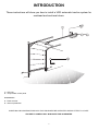
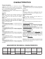
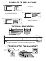
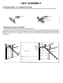
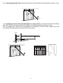
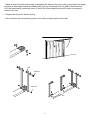
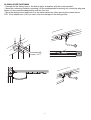
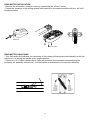
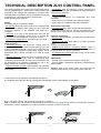
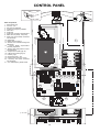
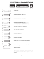
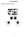
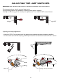
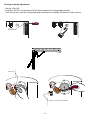
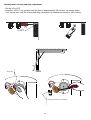
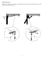
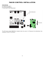
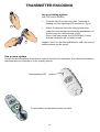
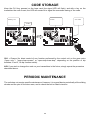
CAME UNITED KINGDOM LTD
UNIT 3
ORCHARD PARK INDUSTRIAL ESTATE,
TOWN STREET, SANDIACRE,
NOTTINGHAM NG10 5BP
TEL: 0115 921 0430
FAX: 0115 921 0431
TECHNICAL
HELPLINE
0115 921 0430
INTERNET - www.cameuk.com
E-MAIL - [email protected]
T
I
K
VER
ns
o
i
t
c
u
r
t
s
n
nI
Installatio
Kit U 4281 includes:
1 x 001 V 600
Gearmotor built-in control panel and courtesy light
1 x 001 AF 43S
Radio receiver 433.92 MHz
1 x 001 TOP-432SA Radio transmitter 433.92 MHz
1 x 001 TOP-A433N Radio antenna 433.92 MHz
Kit U 4281-B includes:
1 x 001 V 600
Gearmotor built-in control panel and courtesy light
1 x 001 AF 43S
Radio receiver 433.92 MHz
1 x 001 TOP-432SA Radio transmitter 433.92 MHz
1 x 001 TOP-A433N Radio antenna 433.92 MHz
1 x 001 DOC-P
Weatherproof pushbutton
1 x 001 V0675
Belt transmission guide
INTRODUCTION
These instructions will show you how to install a VER automatic traction system for
overhead and sectional doors.
1 - VER unit
2 - incorporated control panel
Accessories
3 - Radio receiver
4 - Internal pushbutton
UNDER NO CIRCUMSTANCES SHOULD THIS EQUIPMENT BE OPERATED UNLESS FITTED TO A GATE.
FAILURE TO COMPLY WILL INVALIDATE THE GUARANTEE.
1
CHARACTERISTICS
V0677
Guide unit with belt L = 4,02 m;
- for garage-type doors up to 3,4 m tall with counterweights
- for garage-type doors up to 3,25 m tall with springs and
sectionals
General description:
- Automatic traction system for overhead and sectional
doors;
- Designed and built entirely by CAME Cancelli automatici
S.p.A., in full compliance with current safety standards UNI
8612, and with an IP 40 protecting rating;
- Guaranteed for 12 months, unless tampered with by
unauthorized personnel.
Accessories
V201
Transmission adapter arm for garage-type doors with
counterweights (it substitutes the arm supplied), see pg. 7;
Versions:
V600
Single-phase ratiomotor with mechanical end-stops and
built-in control board; 230V AC power with 50÷60Hz
frequency; 130W max. motor power and up to 500N in
traction power.
V700
Single-phase ratiomotor with mechanical end-stops and
built-in control board; 230V AC power with 50÷60Hz
frequency; 260W max. motor power and up to 850N in
traction power. Sliding guides:
V0671
Guide unit with chain L = 3,02 m; - for garage-type doors up
to 2,4 m tall with counterweights
- for garage-type doors up to 2,2 m tall with springs and
sectionals
V0672
Guide unit with chain L = 3,52 m;
- for garage-type doors up to 2,9 m tall with counterweights
- for garage-type doors up to 2,7 m tall with springs and
sectionals
V0673
Guide unit with chain L = 4,02 m;
- for garage-type doors up to 3,4 m tall with counterweights
- for garage-type doors up to 3,25 m tall with springs and
sectionals
V0675
Guide unit with belt L = 3,02 m;
- for garage-type doors up to 2,4 m tall with counterweights
- for garage-type doors up to 2,2 m tall with springs and
sectionals
V0676
Guide unit with belt L = 3,52 m;
- for garage-type doors up to 2,9 m tall with counterweights
- for garage-type doors up to 2,7 m tall with springs and
sectionals
Optional accessories:
V0670
Emergency battery connection card with support for 2
batteries (12V-1,2Ah - ESCLUSE);
V121
Cable release device and transmission for connection to the
lock;
V122
Improved transmissionarm for sectional gates, see pg. 6;
Technical specifications:
- 24V DC gear motor; reduction gear unit housed in a diecast aluminium casing. The unit features an irreversible
reduction gear with worm screw and helicoidal.
Permanently lubricated with liquid grease.
- ABS automation container and cover with window for lamp
to illuminate the area. The unit is mounted on and
supported by the sliding guide.
- Built-in electric control panel.
- Microswitch end-stops;
- Galvanised cold-formed plate sliding guide; front
tensioning and fastening wall terminal; ABS back motor unit
support and connector terminal. The guide has a built-in
emergency release device and the transmission arm’s
hook; the guide has holes for possible connection of
additional brackets.
- Chain or belt sliding system.
Attention! to insure easy installation and conformance with
current safety, norms, we reccomend installation of CAME
safety and control accessories.
GEAR MOTOR TECHNICAL CHARACTERISTICS
Gear motor
Weight
V600
5,7 Kg
Power Supply
Motor absorption
Max power
6A max
130W
230V a.c.
V700
5,9 Kg
Duty cycle
Traction force
500N
50 %
11A max
260W
2
Average speed
6 m/min
850N
EXAMPLES OF APPLICATIONS
EXAMPLES OF APPLICATIONS
A
AA -- Sectional
door
Sectional door
B
Spring-balanced overhead
door
BB -- Spring-balanced
overhead
door
C
C
Overheaddoor
door
with
counterweight
C -- Overhead
with
counterweight
balancing
balancing or canopy door
*
EXTERNAL DIMENSIONS
212
140
18
400
540 max*
Cable exit
** For
heightsexceding
exceeding
is necessary
to additional
use additional
brackets
or struts
For heights
540540mm,
mm., it isitnecessary
to use
brackets
or struts
POWER SUPPLY PLUG & OUTLET
USE ONLY 250V FUSES
N
L
3
UNIT ASSEMBLY
PREARRANGEMENT OF TRANSMISSION GUIDE
- Fasten the bracket to the transmission guide’s front terminal with the nuts and bolts provided;
M6x14
M6
TRANSMISSION GUIDE FASTENING
- Fasten the transmission guide in the following manner:
a) for sectional doors, fasten the bracket directly to the wall over the spring-release coiling shaft using
adequate dowels and screws; if the distance between the coiling shaft and the gate’s upper ledge is
between 30 and 60 cm, apply the V122 arm (read the technical documentation provided with the
accessory);
=
=
=
30 ÷ 60 cm
=
Upper edge of door
Spring-bar
V122
4
b) for spring garage-type doors, fasten the bracket on the fixed frame with adequate screws or rivets.
=
=
Fig. 1
=
10 ÷ 20 mm
c) for garage-type doors with counterweights or canopy doors, verify the maximum door sliding
point (fig.1) and consequently fasten the bracket on high with adequate screws or rivets.
N.B.: for garage-type doors with counterweights it is necessary to use the V201 adapter arm (read
the technical documentation provided with the accessory).
=
V201
5
- Raise and set the guide horizontally to establish the distance from the ceiling; then fasten the angle
sections or fastening brackets provided (cutting off any excess part) to the guide’s back terminal.
N.B. the transmission guide has three ø7 holes for further fastening should it prove necessary to
reinforce the unit.
- Prepare the chase for electric wiring.
- Lift and fasten the transmission guide to the ceiling at right angles to the wall.
M6
M6x14
M6x14
Ø7
6
SLIDING LEVER FASTENING
- Centrally fix the sliding lever to the door’s upper crosspiece with the rivets provided;
- Mount the unlocking handle by screwing it to the preassembled unlocking unit’s revolving plug and
fasten it in the recommended position with the lock nut;
- Move the sliding runner and hook it to the transmission arm after removing the preset screw.
N.B.: if the adapter arm (V201) is used, hook the carriage to the sliding runner.
7
GEAR MOTOR INSTALLATION
- Remove the automation container cover by unscrewing the ø3.9x13 screw;
- Fasten the container to the sliding guide’s back terminal in the desired position with the ø6.3x45
screws provided;
CAME
ø3,9x13
ø6,3x45
GEAR MOTOR UNLOCKING
- Turn the handle as illustrated; the rehooking of the release will take place automatically at the first
manoeuvre, re-setting the handle in the original position.
- If there is a V121 cable release device (read the technical documentation accompanying the
accessory for assembly instructions), turn the handle as illustrated to lock and the ratiomotor.
V121
8
TECHNICAL DESCRIPTION ZL55 CONTROL PANEL
- Pre-flashing. After an opening or closing command, the
flasher connected to the 10-E flashes for 5 seconds before
beginning the procedure;
- Type of command:
- «open-stop-close-stop» for pushbutton and radio
transmitter;
- «open-close» for pushbutton and radio transmitter;
- «open only» for pushbutton and radio transmitter.
The card is powered with a 230V (AC) power outlet and its
input is protected with a 1.6A line fuse. Control systems are
powered by low voltage and protected by a 315mA fuse.
The total power consumption of 24V accessories (which are
protected by a 3.15A fuse) must not exceed 40W.
Fixed operating time of 80 sec.
Safety
Photocells can be connected to obtain:
- Re-opening during the closing cycle (2-C1), the photocells
on detecting an obstacle while closing the door, cause the
movement direction to be reversed until opening is
complete;
- Total stop (1-2), stop of the garage-type door with the
exclusion of the automatic closing cycle. To resume the
movement, use the pushbutton or the radio control;
- Amperometric safety device: see below, fig A and fig B.
Accessories connected
- Courtesy Light (24V-25W). A light that illuminates the
manoeuvring zone; after an opening command, the light
remains on for a fixed time of 2 minutes and 30 seconds.
Optional accessories
- Courtesy Light (24V-25W), connect it to terminal blocks WE;
- Flashing signal light when gate is in motion (24V-25W
max.),
connect it to terminal blocks 10-E;
- V0670 board card for emergency battery. which is
automatically connected in case of power failure; battery is
recharged when line power is restored;
- AF radiofrequency board (see table on pg. 24) for remote
control.
Other functions
- Automatic closing. The automatic closing timer is
automatically activated at the end of the opening cycle. The
preset, adjustable automatic closing time is automatically
interrupted by the activation of any safety system, and is
deactivated after a STOP command or in case of power
failure;
- Obstacle detection. When the motor is stopped (gate is
closed, open or half-open after an emergency stop
command), the transmitter and the control pushbutton will
be deactivated if an obstacle is detected by one of the
safety devices (for example, the photocells);
- "Operator present" function. Gate operates only when the
pushbutton is held down (the radio remote control system is
deactivated);
Adjustments
- Trimmer TCA = adjustment automatic closing time;
- Trimmer SENS = adjustment sensitivity of amperometric
safety system.
Caution! Shut off the mains power and disconnect the
batteries if fitted before servicing the inside of the unit.
In the presence of an obstacle, the amperometric device:
a) completely stops the door during opening and subsequently closes it automatically (if activated);
b) if in the clos re
b) if in the closure phase, the movement of the door is reversed.
N.B.: In situation (b), if an obstacle is detected three times, the door wing stops during aperture, and automatic closure is
disactivated. Use the keyboard or the radio transmitter to resume movement of the bar.
9
CONTROL PANEL
1
2
BROWN
GREEN/YELLOW
3
4
5
RED
RED
WHITE
WHITE -
0
GREEN
RED
Main compoments
1 - 230V electric plug
2 - Line fuse, 1,6A
3 - End-stop microswitches
4 - Location for emergency batteries
5 - Gear motor
6 - Trasformer
7 - Trasformer connection terminal board
8 - Motor fuse, 8A (V600), 10A (V700)
9 - Gear motor and end-stop connection
terminal board
10 - Signal LED
11 - Radio-code save button
12 - Trimmer TCA: automatic closing time
adjustment
13 - Trimmer SENS: amperometric
sensitivity adjustment
14 - Opening and closing button for endstop adjustment
15 - 10-dip function switch (pag.18)
16 - 2-dip function switch (pag.19)
17 - Courtesy Light
18 - Accessoires fuse, 3,15A
19 - Central control unit fuse, 315mA
20 - Accessory and control connection
terminal board
21 - "AF" radiofrequency board socket
0V
17
230V
26
6
BLUE
RED
WHITE
T.C.A.
SENS.
AP / CH
12
13
14
CH1
7
34V26V17V 0V
FUS. MOTORE 8A
APRE
M N FA FC F
9
8
10
11
15
16
17
18
FUS. CENTR. 630mA
FUS.
ACC. 3,15A
AF
19
21
20
40
ly for V700
BLACK
BLUE
RED
WHITE
T.C.A.
34V26V17V 0V
FUS. MOTORE 8A
M N FA FC F
10
CH1
CH2
APRE
CHIUDE
SENS.
AP / CH
ELECTRICAL CONNECTIONS
M N FA FC F
M
10 11 E E3
1 2 3
7 C1
24 (dc) motor
N
F
Connection limit switch open (N.C.)
FA
F
Connection limit switch closes (N.C.)
FC
+10
-11
Powering accessories (maxc 40W)
- 24V (A.C.) with power supply at 230V (A.C.)
- 23V (D.C.) with power supply at 24V (A.C.)
10
E
24V output in motion (e.g. flashing light)
10
E3
1
24V - 25W max. courtesy light
Pushbutton stop (N.C.)
2
2
Pushbutton opens (N.O.)
3
2
Contact (N.C.) for <<re-aperture during closure>>
C1
2
7
Contact radio and/or button for control (see dip-switch 2-3
function selection)
Antenna connection
N.B. All normally closed (N.C.) contacts and buttons not
used should be disconnected with a dipswitch or shortcircuited.
11
ADJUSTMENTS
Trimmer T.C.A. = Automatic closing time adjustment
Trimmer SENS. = Amperometric sensitivity adjustment
SENS.
AP / CH
APRE
ON
FUS. MOTORE 8A
1 2 3 4 5 6 7 8 9 10
T.C.A.
CH1
ZL55
1 2
FUS. CENTR. 630mA
FUS.
ACC. 3,15A
AF
T.C.A.
SENS.
T.C.A.
SENS.
1"
120"
max.
Minimum power
min.
Maximum power
12
SELECTION OF FUNCTIONS
AP / CH
ON
FUS. MOTORE 8A
ZL55
1 2
FUS. CENTR. 630mA
ON
FUS.
ACC. 3,15A
ON
AF
1 ON
2 ON
2 OFF
3 OFF
4 ON
5 ON
6 ON
7 OFF
8
9
10 ON
10 OFF
OFF
SENS.
1 2 3 4 5 6 7 8 9 10
T.C.A.
CH1
APRE
1 2 3 4 5 6 7 8 9 10
10-way dip-switch
Automatic closure enabled;
"Open-stop-close-stop” with pushbutton (2-7) and radio control (AF board inserted)
enabled;
"Open-close” with pushbutton (2-7) and radio control (AF board inserted) enabled;
"Only opening” with pushbutton (2-7) and radio control (AF board inserted) enabled;
Pre-flashing in opening and closing enabled; After an opening or closing command, the
flascher connected to the 10-E flashes for 5 seconds before beginning the procedure;
Obstacle detection device with motor of limit position enabled; when the motor is stopped
(gate is closed, open or half-open after an emergency stop command), the transmitter and
the control pushbutton will be deactivated if an obstacle is detected by one of the safety
devices (for example, the photocells);
"Operator present" enabled, gate operates only when the pushbutton is held down (the
radio remote control system is deactivated);
Re-opening in closing phase enabled; connect the safety device on terminal (2-C1) the
photocells on detecting an obstacle while closing the door, cause the movement direction
to be reversed until opening is complete;
Not used, keep the dip in position «OFF»;
Not used, keep the dip in position «OFF»;
Enables the function of stopping while closing;
Enables the function of slowing while closing;
2-way dip-switch
SENS.
AP / CH
ON
FUS. MOTORE 8A
1 2 3 4 5 6 7 8 9 10
T.C.A.
CH1
APRE
ON
ZL55
1 2
FUS. CENTR. 630mA
FUS.
ACC. 3,15A
AF
1 ON
1 OFF
2
Control unit enabled for V600 gear motor;
Control unit enabled for V700 gear motor;
Not used, keep the dip in position «OFF»;
13
1 2
OFF
ADJUSTING THE LIMIT SWITCHES
IMPORTANT: READ INSTRUCTIONS CAREFULLY BEFORE PROCEEDING WITH ADJUSTMENTS.
During opening there is only one end-stop mode;
During closing there is the possibility of slowing down before stopping.
Set dip 6 to ON during all the subsequent adjustments. Turn it back to OFF when finished.
T.C.A.
AP / CH
SENS.
AP / CH
8
7
6
5
4
3
ON
2
1 2
ON
6 ON
9 10
3 4 5 6 7 8 9 10
SENS.
1
.A.
6 OFF
Opening end-stop adjustment
- Keep the “AP/CH” key pressed until the garage door reaches the desired opening position;
- turn the white cam until the opening end-stop microswitch is inserted and secure it with a screw.
AP / CH
1 2 3 4 5 6 7 8 9 10
SENS.
ON
T.C.A.
Opening end-stop microswitch
White cam
14
Closing end-stop adjustment
- Set dip 10 to ON.
- Keep the "AP/CH" key pressed until the door reaches the closing ledge position.
- Turn the red cam until the closing end-stop microswitch is inserted and secure it with a screw.
T.C.A.
AP / CH
SENS.
AP / CH
ON
1
ON
2
3
4
10 ON
Red cam
Closing end-stop microswitch
15
1 2
5
6
7
8
3 4 5 6 7 8 9 10
9 10
SENS.
Slowing when closing end-stop adjustment
- Set dip 10 to OFF.
- Keep the “AP/CH” key pressed until the door is approximately 20 cm from the closing ledge;
- Turn the red cam until the closing end-stop microswitch is inserted and secure it with a screw.
T.C.A.
AP / CH
ON
AP / CH
3 4 5 6 7 8 9 10
20 cm
Closing end-stop microswitch
16
1 2
ON
10 OFF
Red cam
SENS.
3 4 5 6 7 8 9 10
SENS.
1 2
T.C.A.
Safety screw-locks
With the door either open or closed, set safety screw-locks placed in the transmission guide on the
sliding runner and screw them on.
SLIDING BLOCK
SLIDING BLOCK
MECHANICAL END-STOP
MECHANICAL END-STOP
17
RADIO CONTROL INSTALLATION
PROCEDURE
A. insert an AF card **.
B. encode transmitter/s.
C. store code in the motherboard.
AP / CH
3 4 5 6 7 8 9 10
SENS.
ON
APRE
MOTHERBOARD
1 2
T.C.A.
CH1
ZL55
1 2
"AF" BOARD
AF
The AF board should ALWAYS be inserted when the power is off because the motherboard only
recognises it when it is powered.
18
TRANSMITTER ENCODING
Use on existing system
(with TOP at 433.92 MHz)
1.
Press the key to encode until, after 7 seconds of
flashing, the red signalling LED remians on. (fig A)
2.
Within 10 seconds, bring the existing transmitter
closer from the rear part and press the pushbutton you
want to copy for a few seconds. (fig B)
Once it has been saved, the LED will flash 3 times
and the transmitter will be ready for use.
A
B
Repeat 1 and 2 for the other pushbuttons. (NB: the code of
another system can be saved).
Use on new system
Consult the documentation of the electric board to save the first transmitter, then follow the procedure
described above to duplicate it in the quantity desired.
Red signalling LED
To open battery compartment, press and slide.
19
CODE STORAGE
Keep the CH1 key pressed on the base card (the signal LED will flash), and with a key on the
transmitter the code is sent, the LED will remain lit to signal the successful saving of the code.
Lit LED
Flashing Led
"AF" board
"CH1"
CH1
AP / CH
CH1
AP / CH
APRE
APRE
ZL55
ZL55E
1 2
1 2
ZL55
ZL55E
FUS. MOTORE 8A
FUS. MOTORE 8A
FUS. CENTR. 630mA
FUS. CENTR. 630mA
FUS.
ACC. 3,15A
A
AF
AF
CH1 = Channel for direct control of one function performed by the control unit on the gear motor
("open only" / "open-close-reverse" or "open-stop-close-stop", depending on the position of dip
switches 2 and 3, 10-dip function switch).
N.B. If you wish to change the code on your transmitters in the future, simply repeat the procedure
described above.
PERIODIC MAINTENANCE
The unit does not require specific maintenance. However, it is a good idea to periodically oil the sliding
wheels and the pins of the door arms, and to check the belt or chain’s tension.
PERIODIC MAINTENANCE
20
CONTACT INFORMATION
CAME UNITED KINGDOM LTD
UNIT 3
ORCHARD PARK INDUSTRIAL ESTATE
TOWN STREET, SANDIACRE, NOTTINGHAM NG10 5BP
TEL: 0115 921 0430
FAX: 0115 921 0431
INTERNET : www.cameuk.com
E-MAIL: [email protected]
THIS INSTALLATION WAS COMPLETED BY:
.........................................................................
NAME..............................................................
ADDRESS........................................................
.........................................................................
.........................................................................
.........................................................................
TEL........................ MOBILE............................
DATE OF INSTALLATION................................

![Streptex [FR] - Thermo Scientific](http://vs1.manualzilla.com/store/data/006477074_1-c3b6e979a593bf0d3b4868708af7b22c-150x150.png)