1
Agilent 81600B
Tunable Laser Source Family
User’s Guide
Agilent Technologies
Notices
© Agilent Technologies, Inc. 2002 - 2005
Warranty
No part of this manual may be reproduced
in any form or by any means (including
electronic storage and retrieval or translation into a foreign language) without prior
agreement and written consent from Agilent Technologies, Inc. as governed by
United States and international copyright
laws.
Agilent Technologies, Deutschland GmbH
Herrenberger Straße 130
71034 Böblingen, Germany.
The material contained in this document is provided “as is,” and is subject
to being changed, without notice, in
future editions. Further, to the maximum extent permitted by applicable
law, Agilent disclaims all warranties,
either express or implied, with regard
to this manual and any information
contained herein, including but not limited to the implied warranties of merchantability and fitness for a particular
purpose. Agilent shall not be liable for
errors or for incidental or consequential damages in connection with the
furnishing, use, or performance of this
document or of any information contained herein. Should Agilent and the
user have a separate written agreement with warranty terms covering the
material in this document that conflict
with these terms, the warranty terms
in the separate agreement shall control.
Subject Matter
Technology Licenses
Manual Part Number
81600-90B12
Edition
Fourth edition, January 2005
Third edition, August 2004
Second edition, July 2003
First edition, November 2002
Printed in Germany
The material in this document is
subject to change without notice.
Agilent Technologies makes no
warranty of any kind with regard to this
printed material, including, but not
limited to, the implied warranties of
merchantability and fitness for a
particular purpose.
Agilent Technologies shall not be
liable for errors contained herein or for
incidental or consequential damages
in connection with the furnishing,
performance, or use of this material.
The hardware and/or software
described in this document are furnished under a license and may be
used or copied only in accordance with
the terms of such license.
Restricted Rights Legend
If software is for use in the performance of a U.S. Government prime
contract or subcontract, Software is
delivered and licensed as “Commercial
computer software” as defined in
DFAR 252.227-7014 (June 1995), or as
a “commercial item” as defined in FAR
2.101(a) or as “Restricted computer
software” as defined in FAR 52.227-19
(June 1987) or any equivalent agency
regulation or contract clause. Use,
duplication or disclosure of Software is
subject to Agilent Technologies’ standard commercial license terms, and
non-DOD Departments and Agencies
of the U.S. Government will receive no
greater than Restricted Rights as
defined in FAR 52.227-19(c)(1-2) (June
1987). U.S. Government users will
receive no greater than Limited Rights
as defined in FAR 52.227-14 (June
1987) or DFAR 252.227-7015 (b)(2)
(November 1995), as applicable in any
technical data.
Safety Notices
CAU T ION
A CAUTION notice denotes a
hazard. It calls attention to an
operating procedure, practice, or
the like that, if not correctly
performed or adhered to, could
result in damage to the product
or loss of important data. Do not
proceed beyond a CAUTION
notice until the indicated
conditions are fully understood
and met.
WARN IN G
A WARNING notice denotes a
hazard. It calls attention to an
operating procedure, practice,
or the like that, if not correctly
performed or adhered to, could
result in personal injury or
death. Do not proceed beyond a
WARNING notice until the
indicated conditions are fully
understood and met.
Agilent Technologies Sales and Service Offices
For more information about Agilent Technologies test and measurement
products, applications, services, and for a current sales office listing, viesit
our web site:
http://www.agilent.com/comms/lightwave
You can also contact one of the following centers and ask for a test and
measurement sales representative.
United States:
1 800 829 4444
1 800 829 4433 (FAX)
Canada:
1 877 894 4414
1888 900 8921 (FAX)
Europe:
(31 20) 547 2111
(31 20) 547 2190 (FAX)
Japan:
0120 421 345
0120 421 678 (FAX)
Mexico
(52 55) 5081 9469
(52 55) 5081 9467 (FAX)
Australia:
1 800 629 485
1 800 142 134 (FAX)
Asia-Pacific:
800 930 871
800 908 476 (FAX)
Brazil
(55 11) 4197 3600
(55 11) 4197 3800 (FAX)
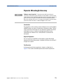
In This Guide....
This User’s Guide contains information about the
Agilent 81600B Tunable Laser Source Family.
1
Getting Started with the Agilent 81600B Tunable Laser Source
Family
This chapter contains an introductory description of the Tunable Laser
Source Family and aims to make the modules familair to you.
2
Accessories
Describes the accessories available for each member of the Tunable Laser
Source Family.
3
Specifications
After a Definition of Terms section (these terms are used here and for the
Performance Tests), provides complete Agilent 81600B Family Tunable
Laser Source Module Specifications.
4
Performance Tests
Describes the tests used to verify the Performance of each member of the
Tunable Laser Source Family, and provides Test Record forms.
5
Cleaning Procedures for Lightwave Test and Measurement
Equipment
Provides advice on cleaning materials and methods for this, and
associated, optical equipment.
Table of Contents
Getting Started with the Agilent 81600B Tunable Laser Source Family 11
General Safety Considerations
12
Safety Symbols
Initial Inspection
Line Power Requirements
Operating Environment
Input/Output Signals
Storage and Shipment
12
Initial Safety Information for Agilent 81600B family
modules
Laser Safety Labels
What is a Tunable Laser?
Installation
Front Panels
Front Panel Controls and Indicators
Typical Use Models
Optical Output
Polarization Maintaining Fiber
Angled and Straight Contact Connectors
Signal Input and Output
Accessories
13
13
13
14
14
15
16
17
17
18
18
19
21
21
21
23
25
Agilent 81600B Family Tunable Laser Source Modules and
Options
26
Module Options
28
Options
Connector Interfaces and Other Accessories
Option 071: Straight Contact Connector
Option 072: Angled Contact Connector
Agilent 81600B Tunable Laser Source Family, Fourth Edition
30
30
31
31
5
Specifications
33
Definition of Terms
35
General Definitions
Absolute wavelength accuracy (continuous sweep mode)
Absolute wavelength accuracy (stepped mode)
Attenuation
Dynamic power reproducibility (continuous sweep mode)
Dynamic relative power flatness (continuous sweep mode)
Effective linewidth
External analog modulation - modulation depth
External digital modulation - delay time
Internal digital modulation - duty cycle
Linewidth
Maximum output power
Mode-hop free tunability
Operating temperature and humidity
Output isolation
Polarization extinction ratio
Power flatness versus wavelength
Power linearity
Power repeatability
Power stability
Relative intensity noise (RIN)
Relative wavelength accuracy (continuous sweep mode)
Relative wavelength accuracy (stepped mode)
Return loss
Side-mode suppression ratio
Signal to source spontaneous emission (SSE) ratio
Signal to total source spontaneous emission ratio
Wavelength range
Wavelength repeatability (continuous sweep mode)
Wavelength repeatability (stepped mode)
Wavelength resolution
Wavelength stability
Agilent 81600B Family Tunable Laser Source Module
Specifications
Conditions
6
36
37
37
37
38
38
38
39
39
39
40
40
41
41
41
42
42
43
43
44
44
45
45
46
46
46
47
48
48
49
49
50
51
66
Agilent 81600B Tunable Laser Source Family, Fourth Edition
Supplementary Performance Characteristics
General
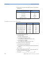
Performance Tests
68
69
71
Required Test Equipment
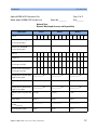
Test Record
Test Failure
Instrument Specification
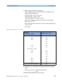
Performance Test Instructions
General test Setup
Wavelength Meter Settings for all Wavelength Tests
Wavelength Accuracy
Absolute and Relative Wavelength Accuracy
Mode-Hop Free Tuning
Wavelength Repeatability
Power Tests
Maximum Output Power
Power Linearity
Power Flatness versus Wavelength
Power Stability
Signal-to-Source Spontaneous Emission Ratio
Signal-to-Source Spontaneous Emission Ratio
- Low SSE Output
Signal-to-Total-Source Spontaneous Emission Ratio
- Low SSE Ouptput
Optional Performance Tests
Signal-to-Total-Source Spontaneous Emission Ratio
- High Power Output
Dynamic Wavelength Accuracy
Dynamic Absolute and Relative Wavelength Uncertainty
Dynamic Wavelength Repeatability
Normalized Sweep Acceleration
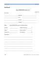
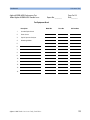
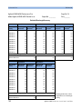
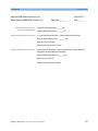
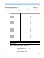
Test Records
Agilent 81600B Tunable Laser Source Family, Fourth Edition
73
74
74
74
75
75
76
77
77
81
84
88
88
91
99
107
112
116
122
131
131
135
142
144
145
146
7
Cleaning Procedures for Lightwave Test and Measurement Equipment 243
Safety Precautions
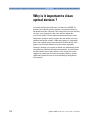
Why is it important to clean optical devices ?
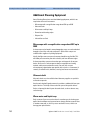
What materials do I need for proper cleaning?
Standard Cleaning Equipment
Additional Cleaning Equipment
Preserving Connectors
General Cleaning Procedure
How to clean connectors
How to clean optical head adapters
How to clean connector interfaces
How to clean bare fiber adapters
How to clean lenses and instruments with an optical
glass plate
How to clean instruments with a fixed connector
interface
How to clean instruments with a physical contact
interface
How to clean instruments with a recessed lens interface
How to clean optical devices that are sensitive to
mechanical stress and pressure
How to clean metal filters or attenuating mesh filters
Additional Cleaning Information
How to clean bare fiber ends
How to clean large area lenses and mirrors
Other Cleaning Hints
Index
8
245
246
247
247
250
252
254
254
256
257
258
259
260
261
262
263
264
265
265
266
268
269
Agilent 81600B Tunable Laser Source Family, Fourth Edition
List of Figures
Figure 1
Figure 2
Figure 3
Figure 4
Figure 5
Figure 6
Figure 7
Figure 8
Figure 9
Figure 10
Figure 11
Figure 12
Figure 13
Figure 14
Figure 15
Figure 16
Figure 17
Figure 18
Figure 19
Figure 20
Figure 21
Figure 22
Figure 23
Figure 24
Figure 25
Figure 26
Figure 27
Figure 28
Figure 29
Figure 30
Figure 31
Figure 32
Figure 33
Figure 34
Figure 35
Figure 36
Figure 37
Figure 38
Agilent 81600B Tunable Laser Source Family, Fourth Edition
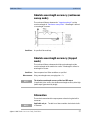
Agilent 81600B Tunable Laser Source Family modules
(dual output, angled contact connectors) . . . . . . . . . . . . . . . . . . . . . . . 18
Agilent 81600B Tunable Laser Source Family module
(single output, straight contact connectors) . . . . . . . . . . . . . . . . . . . . 18
PMF Output Connector . . . . . . . . . . . . . . . . . . . . . . . . . . . . . . . . . . . . . . 21
Angled and Straight Contact Connector Symbols . . . . . . . . . . . . . . . . 22
Agilent 81600B Tunable Laser Module (angled contact connector) 22
Agilent 8164A/B mainframes, Agilent 81600B Family Tunable
LaserSource modules, and Options . . . . . . . . . . . . . . . . . . . . . . . . . . . . 26
Absolute wavelength accuracy (continuous sweep mode) . . . . . . . . 37
Dynamic power reproducibility (continuous sweep mode) . . . . . . . . 38
Maximum Output Power vs Wavelength, Maximum Flat Output
Power vs Wavelength . . . . . . . . . . . . . . . . . . . . . . . . . . . . . . . . . . . . . . . 40
Circular traces on the Poincaré sphere used to calculate
polarization extinction ratio. . . . . . . . . . . . . . . . . . . . . . . . . . . . . . . . . . . 42
Power flatness vs. wavelength. . . . . . . . . . . . . . . . . . . . . . . . . . . . . . . . 42
Power linearity. . . . . . . . . . . . . . . . . . . . . . . . . . . . . . . . . . . . . . . . . . . . . . 43
Power stability. . . . . . . . . . . . . . . . . . . . . . . . . . . . . . . . . . . . . . . . . . . . . . 44
Relative wavelength accuracy (continuous sweep mode). . . . . . . . . 45
Relative wavelength accuracy. . . . . . . . . . . . . . . . . . . . . . . . . . . . . . . . . 45
Signal to source spontaneous emission ratio. . . . . . . . . . . . . . . . . . . . 47
Signal to total source spontaneous emission ratio. . . . . . . . . . . . . . . 47
Wavelength repeatability (continuous sweep mode). . . . . . . . . . . . . 48
Test Setup for Wavelength Tests . . . . . . . . . . . . . . . . . . . . . . . . . . . . . . 75
Absoute and Relative Wavelength Accuracy. . . . . . . . . . . . . . . . . . . . 78
Mode-hop free Tuning Range. . . . . . . . . . . . . . . . . . . . . . . . . . . . . . . . . 81
Wavelength Repeatability. . . . . . . . . . . . . . . . . . . . . . . . . . . . . . . . . . . . 85
Maximum Output Power. . . . . . . . . . . . . . . . . . . . . . . . . . . . . . . . . . . . . 88
Test Setup for Maximum Output Power Tests . . . . . . . . . . . . . . . . . . . 89
Power Linearity. . . . . . . . . . . . . . . . . . . . . . . . . . . . . . . . . . . . . . . . . . . . . 91
Test Setup for Power Linearity Tests . . . . . . . . . . . . . . . . . . . . . . . . . . 92
Test Setup for Power Linearity Tests using built-in attenuator . . . . 97
Power Flatness. . . . . . . . . . . . . . . . . . . . . . . . . . . . . . . . . . . . . . . . . . . . . . 99
Test Setup for Power Flatness Tests - Low SSE output . . . . . . . . . . 100
Test Setup for Power Flatness Tests - High Power output,
without using attenuator . . . . . . . . . . . . . . . . . . . . . . . . . . . . . . . . . . . . 102
Test Setup for Power Flatness Tests - High Power output, using
the built-in attenuator . . . . . . . . . . . . . . . . . . . . . . . . . . . . . . . . . . . . . . 104
Stability of Power Output versus Time. . . . . . . . . . . . . . . . . . . . . . . . .107
Test Setup for Power Stability Tests . . . . . . . . . . . . . . . . . . . . . . . . . . 108
Signal-to-Source Spontaneous Emission Ratio. . . . . . . . . . . . . . . . . 112
Test Setup for Signal-to-Source Spontaneous Emission Test
- High Power Output . . . . . . . . . . . . . . . . . . . . . . . . . . . . . . . . . . . . . . . . 113
Transmission Characteristics of Fiber Bragg Grating . . . . . . . . . . . . 116
Test Setup for Signal-to-Source Spontaneous Emission Test
- Low SSE Output. . . . . . . . . . . . . . . . . . . . . . . . . . . . . . . . . . . . . . . . . . . 117
Total SSE Measurement. . . . . . . . . . . . . . . . . . . . . . . . . . . . . . . . . . . . . 123
9
Figure 39
Figure 40
Figure 41
Figure 42
Figure 43
Figure 44
10
Test Setup for Total Source Spontaneous Emission Test
- Low SSE output . . . . . . . . . . . . . . . . . . . . . . . . . . . . . . . . . . . . . . . . . .
Test Setup for Total Source Spontaneous Emission Test
- High Power output . . . . . . . . . . . . . . . . . . . . . . . . . . . . . . . . . . . . . . .
Test Flow - Dynamic Wavelength Accuracy Measurements . . . . .
Setup for wavelength uncertainty verification in swept mode . . .
Optimization of reference scans. Sampling points as circled,
threshold in dashed line. . . . . . . . . . . . . . . . . . . . . . . . . . . . . . . . . . . .
Measurement Setup to Determine the Sweep Speed . . . . . . . . . . .
123
131
136
137
140
145
Agilent 81600B Tunable Laser Source Family, Fourth Edition
1
Getting Started with the Agilent 81600B
Tunable Laser Source Family
This chapter describes the Agilent 81600B Tunable Laser Source Family.
General Safety Considerations. . . . . . . . . . . . . . . . . . . . . . . 12
Initial Inspection . . . . . . . . . . . . . . . . . . . . . . . . . . . . . . . . . . . . . . . 13
Safety Symbols . . . . . . . . . . . . . . . . . . . . . . . . . . . . . . . . . . . . . . . . 12
Line Power Requirements . . . . . . . . . . . . . . . . . . . . . . . . . . . . . . . 13
Operating Environment . . . . . . . . . . . . . . . . . . . . . . . . . . . . . . . . . 13
Input/Output Signals . . . . . . . . . . . . . . . . . . . . . . . . . . . . . . . . . . . 14
Storage and Shipment . . . . . . . . . . . . . . . . . . . . . . . . . . . . . . . . . . 14
Initial Safety Information for Agilent 81600B family
modules . . . . . . . . . . . . . . . . . . . . . . . . . . . . . . . . . . . . . . . . . . 15
Laser Safety Labels . . . . . . . . . . . . . . . . . . . . . . . . . . . . . . . . 16
What is a Tunable Laser? . . . . . . . . . . . . . . . . . . . . . . . . . . . 17
Installation . . . . . . . . . . . . . . . . . . . . . . . . . . . . . . . . . . . . . . . . . . . . 17
Front Panels. . . . . . . . . . . . . . . . . . . . . . . . . . . . . . . . . . . . . . . . . . . 18
Front Panel Controls and Indicators . . . . . . . . . . . . . . . . . . . . . . 18
Typical Use Models . . . . . . . . . . . . . . . . . . . . . . . . . . . . . . . . 19
Optical Output. . . . . . . . . . . . . . . . . . . . . . . . . . . . . . . . . . . . . 21
Polarization Maintaining Fiber . . . . . . . . . . . . . . . . . . . . . . . . . . . 21
Angled and Straight Contact Connectors . . . . . . . . . . . . . . . . . . 21
Signal Input and Output . . . . . . . . . . . . . . . . . . . . . . . . . . . . 23
Agilent 81600B Tunable Laser Source Family, Fourth Edition
11
Getting Started with the Agilent 81600B Tunable Laser Source Family
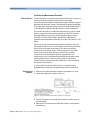
General Safety Considerations
General Safety Considerations
The following general safety precautions must be observed during all
phases of operation, service, and repair of this instrument. Failure to
comply with these precautions or with specific warnings elsewhere in this
manual violates safety standards of design, manufacture, and intended
use of the instrument. Agilent Technologies Inc. assumes no liability for
the customer’s failure to comply with these requirements.
Before operation, review the instrument and manual, including the red
safety page, for safety markings and instructions. You must follow these to
ensure safe operation and to maintain the instrument in safe condition.
WARN
CAU T ION
IN G
The WARNING sign denotes a hazard. It calls attention to a
procedure, practice or the like, which, if not correctly performed
or adhered to, could result in injury or loss of life. Do not proceed
beyond a WARNING sign until the indicated conditions are fully
understood and met.
Safety Symbols
The apparatus will be marked with this symbol when it is necessary for the
user to refer to the instruction manual in order to protect the apparatus
against damage.
Hazardous laser radiation.
12
Agilent 81600B Tunable Laser Source Family, Fourth Edition
General Safety Considerations
Getting Started with the Agilent 81600B Tunable Laser Source Family
Initial Inspection
Inspect the shipping container for damage. If there is damage to the
container or cushioning, keep them until you have checked the contents of
the shipment for completeness and verified the instrument both
mechanically and electrically.
The Performance Tests give procedures for checking the operation of the
instrument. If the contents are incomplete, mechanical damage or defect
is apparent, or if an instrument does not pass the operator’s checks, notify
the nearest Agilent Technologies Sales/Service Office.
WARN
CAU T ION
IN G
WARN
CAU T ION
IN G
To avoid hazardous electrical shock, do not perform electrical
tests when there are signs of shipping damage to any portion of
the outer enclosure (covers, panels, etc.).
You MUST return instruments with malfunctioning laser modules
to an Agilent Technologies Sales/Service Center for repair and
calibration.
Line Power Requirements
An Agilent 81600B Tunable Laser Source Family module operates when
installed in the Agilent 8164A/B Lightwave Measurement System.
Operating Environment
The safety information in the Agilent 8164A/B Lightwave Multimeter (and
the Agilent 8163A/B Lightwave Measurement System, & Agilent 8166A/B
Lightwave Multichannel System) User’s Guide summarizes the operating
ranges for the Agilent 81600B Tunable Laser Source Family modules. In
order for these modules to meet specifications, the operating environment
must be within the limits specified for your mainframe.
Agilent 81600B Tunable Laser Source Family, Fourth Edition
13
Getting Started with the Agilent 81600B Tunable Laser Source Family
General Safety Considerations
Input/Output Signals
CAU T ION
There are two BNC connectors on the front panel of the
Agilent 81600B; a BNC input connector and a BNC output
connector.
An absolute maximum of ±6 V can be applied as an external voltage
to any BNC connector.
Storage and Shipment
These modules can be stored or shipped at temperatures between -40°C
and +70°C. Protect the module from temperature extremes that may cause
condensation within it.
14
Agilent 81600B Tunable Laser Source Family, Fourth Edition
Initial Safety Information for Agilent 81600B family modulesGetting Started with the Agilent 81600B Tunable Laser Source Family
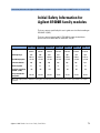
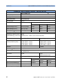
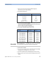
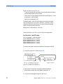
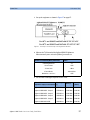
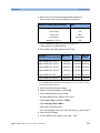
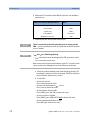
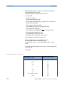
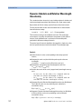
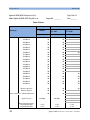
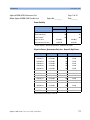
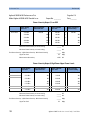
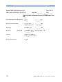
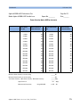
Initial Safety Information for
Agilent 81600B family modules
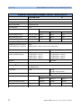
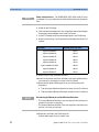
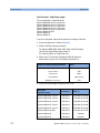
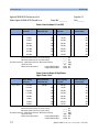
The laser sources specified by this user’s guide are classified according to
IEC 60825-1 (2001).
The laser sources comply with 21 CFR 1040.10 except for deviations
pursuant to Laser Notice No. 50 dated 2001-July-26.
81660B #200 81600B #160 81600B #150 81600B #140 81600B #130 81600B #142 81600B #132
Laser Type
EC-Laser
InGaAsP
EC-Laser
InGaAsP
EC-Laser
InGaAsP
EC-Laser
InGaAsP
EC-Laser
InGaAsP
EC-Laser
InGaAsP
EC-Laser
InGaAsP
Wavelength range
1440 1640 nm
1495 1640 nm
1450 1590 nm
1370 1495 nm
1260 1375 nm
1370 1495 nm
1260 1375 nm
Max. CW output power
<15 mW
<15 mW
<15 mW
<15 mW
<15 mW
<15 mW
<15 mW
Beam waist diameter
9 µm
9 µm
9 µm
9 µm
9 µm
9 µm
9 µm
Numerical apeture
0.1
0.1
0.1
0.1
0.1
0.1
0.1
Laser Class according to
IEC 60825-1 (2001)
1M
1M
1M
1M
1M
1M
1M
163 mW
163 mW
163 mW
52 mW
52 mW
52 mW
52 mW
Max. permissible CW
output power
* Max. CW output power is defined as the highest possible optical power that the laser source can produce at its output
connector.
Agilent 81600B Tunable Laser Source Family, Fourth Edition
15
Getting Started with the Agilent 81600B Tunable Laser Source Family
Laser Safety Labels
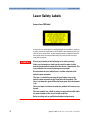
Laser Safety Labels
Laser class 1M label
A sheet of laser safety labels is included with the laser module as required.
In order to meet the requirements of IEC 60825-1 we recommend that you
stick the laser safety labels, in your language, onto a suitable location on
the outside of the instrument where they are clearly visible to anyone
using the instrument.
WARN
CAU T ION
IN G
Please pay attention to the following laser safety warning:
Under no circumstances look into the end of an optical cable
attached to the optical output when the device is operational. The
laser radiation can seriously damage your eyesight.
Do not enable the laser when there is no fiber attached to the
optical output connector.
The laser is enabled by pressing the gray button close to the
optical output connector on the front panel of the module. The
laser is on when the green LED on the front panel of the instrument
is lit.
The use of optical instruments with this product will increase eye
hazard.
The laser module has a built-in safety circuitry which will disable
the optical output in the case of a fault condition
Refer servicing only to qualified and authorised personnel.
16
Agilent 81600B Tunable Laser Source Family, Fourth Edition
What is a Tunable Laser?
Getting Started with the Agilent 81600B Tunable Laser Source Family
What is a Tunable Laser?
A Tunable Laser is a laser source for which the wavelength can be varied
through a specified range. The Agilent Technologies range of Tunable
Laser modules also allow you to set the output power, and to choose
between continuous wave or modulated power.
Installation
Every Agilent 81600B Tunable Laser Source Family module is backloadable
into Slot 0 of an Agilent 8164A/B mainframe; see “How to Fit and Remove
Modules” in the Agilent 8163A/B Lightwave Multimeter,
Agilent 8164A/B, Lightwave Measurement System, & Agilent 8166A/B
Lightwave Multichannel System User’s Guide.
Agilent 81600B Tunable Laser Source Family, Fourth Edition
17
Getting Started with the Agilent 81600B Tunable Laser Source Family
What is a Tunable Laser?
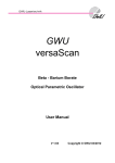
Front Panels
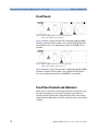
Figure 1 Agilent 81600B Tunable Laser Source Family modules
(dual output, angled contact connectors)
Figure 1 illustrates a typical front panel for a dual-output Agilent 81600B
Tunable Laser Source Family module, such as options #200, #160, #150,
#140 or #130. In this case, angled contact interfaces (81600B-072) are
specified.
Figure 2 Agilent 81600B Tunable Laser Source Family module
(single output, straight contact connectors)
Figure 2 illustrates a typical front panel for a single-output Agilent 81600B
Tunable Laser Source Family module, such as options #142 or #132. In
this case, straight contact interfaces (81600B#071) are specified.
Front Panel Controls and Indicators
Switch the laser source on or off using the switch on its frontpanel, using
the [State] parameter in the instrument’s Graphical User Interface, or
remotely using GP-IB commands. When the Active LED is lit the souce is
emitting radiation. When the Active LED is not lit the source is not emitting
radiation.
18
Agilent 81600B Tunable Laser Source Family, Fourth Edition
Typical Use Models
Getting Started with the Agilent 81600B Tunable Laser Source Family
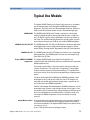
Typical Use Models
The Agilent 81600B Tunable Laser Source Family consists of six modules
that fit into the bottom slot of the Agilent 8164B Lightwave Solution
Mainframe. The family covers the full wavelength range from 1260 nm to
1640 nm with the minimum number of lasers and no wavelength gaps.
81600B #200
81600B #160, 150, 140, 130
81600B #142, 132
Testing CWDM and DWDM
components
The 81600B option 200 All-band Tunable Laser Source is the flagship
module, featuring the widest tuning range of 200 nm with a single laser
and a 70 dB/nm signal-to-source spontaneous emission ratio (signal-toSSE ratio). The excellent low-SSE performance typically allows crosstalk
measurements of better than 70 dB for an 8 channel CWDM multiplexer.
The 81600B option 160, 150, 140 and 130 Tunable Laser Sources offer other
wavelength ranges and are equipped with two optical outputs, like the
option 200. By selecting the port, high power or low-SSE can be obtained.
The 81600B option 142 and 132 Tunable Laser Sources have a single high
power output port. The 81600B option 132 covers the wavelength range
from 1260 nm to 1375 nm.
The Agilent 81600B Tunable Laser Source Family provides test
instrumentation with the flexibility, efficiency and performance required for
WDM component tests.
The testing of optical filters is based on a generic principle, namely the
stimulus-response test. The state-of-the- art approach is a wavelength
resolved stimulus-response measurement utilizing a TLS capable of fast
and precise sweeps across the entire wavelength range, and optical power
meters.
For Dense Wavelength Division Multiplexer (DWDM) components, high
wavelength accuracy and dynamic range are critical. The modules are
mode-hop free tunable with continuous output power, so qualify for the
test of the most critical DWDM components.
For Coarse Wavelength Division Multiplexer (CWDM) components, a wide
wavelength range, dynamic range and tight costing are key targets. If the
investment in the test solution can be shared among many different type of
filters, the contribution to each individual filter is minimized. In this way,
cost targets for CWDM components can be met without sacrificing
accuracy.
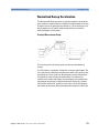
Swept Measurements
As manufacturing yield expectations becomes more and more stringent, it
is important that all instruments deliver optimum performance under all
measurement conditions. The Agilent 81600B Tunable Laser Source Family
can sweep as fast as
80 nm/s with specified accuracy during the sweep.
Agilent 81600B Tunable Laser Source Family, Fourth Edition
19
Getting Started with the Agilent 81600B Tunable Laser Source Family
High Dynamic Range
Typical Use Models
The low SSE output port delivers a signal with ultra-low source
spontaneous emission. It enables accurate cross-talk measurement of
DWDM and CWDM wavelength filtering components by producing light
only at the desired wavelength.
For example, you can characterize steep notch filters such as Fiber Bragg
Gratings by using the low SSE output and a power sensor module.
High Power
For Agilent 81600B options 200, 160, 150,140 and 130, the second output
port provides high optical power, adjustable over a power range of more
than 60 dB via a built-in optical attenuator.
The Agilent 81600B options 142 and 132 simply provide an output port with
high stimulus power for applications where the SSE level is not critical.
The 81600B option 142 can also be equiped with a built-in optical
attenuator (option #003), so providing an adjustable power range of 60 dB.
Precision
Testing Integrated Optical
devices
20
Every Agilent 81600B Tunable Laser Source Family module includes a builtin real time wavelength meter which realizes an absolute wavelength
accuracy of ±10 pm (typ. ±3.6 pm) as a standalone instrument.
The 81600B Tunable Laser Source Family’s PMF output ports provide a
well-defined state of polarization to ensure constant measurement
conditions for waveguide devices. A PMF cable easily connects to an
external optical modulator.
Agilent 81600B Tunable Laser Source Family, Fourth Edition
Optical Output
Getting Started with the Agilent 81600B Tunable Laser Source Family
Optical Output
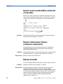
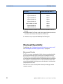
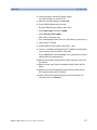
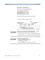
Polarization Maintaining Fiber
All Agilent 81600B Tunable Laser Source Family modules include
polarization maintaining fiber (PMF) outputs, aligned to maintain the state
of polarization.
The fiber is of Panda type, with TE mode in the slow axis in line with the
connector key. A well defined state of polarization ensures constant
measurement conditions.
E
Connector Key
Fiber Cladding
H
Fiber Core
(9-µm Diameter)
Stress Rods
Slow Axis (Polarization Axis)
Not to Scale
Figure 3 PMF Output Connector
Angled and Straight Contact Connectors
Angled contact connectors help you to control return loss. With angled
fiber endfaces, reflected light tends to reflect into the cladding, reducing
the amount of light that reflects back to the source.
Agilent 81600B Tunable Laser Source Family modules can have the
following connector interface options:
• Option 071, Polarization-maintaining fiber straight contact connectors,
or
• Option 072, Polarization-maintaining fiber angled contact connectors.
Agilent 81600B Tunable Laser Source Family, Fourth Edition
21
Getting Started with the Agilent 81600B Tunable Laser Source Family
CAU T ION
Optical Output
If the contact connector on your instrument is angled, you can only
use cables with angled connectors with the instrument.
Angled Contact
Connector Symbol
Straight Contact
Connector Symbol
Figure 4 Angled and Straight Contact Connector Symbols
Figure 4 shows the symbols that tell you whether the contact connector
of your Tunable Laser Source module is angled or straight. The angled
contact connector symbol is colored green.
Figure 2 and Figure 5 shows the front panel of the Agilent 81600B
Family Tunable Laser Source module with straight and angled contact
connectors respectively.
You should connect straight contact fiber end connectors with neutral
sleeves to straight contact connectors and connect angled contact fiber
end connectors with green sleeves to angled contact connectors.
N O TE
You cannot connect angled non-contact fiber end connectors with orange
sleeves directly to the instrument.
Figure 5 Agilent 81600B Tunable Laser Module (angled contact connector)
See “Accessories” on page 25 for further details on connector interfaces
and accessories.
22
Agilent 81600B Tunable Laser Source Family, Fourth Edition
Signal Input and Output
Getting Started with the Agilent 81600B Tunable Laser Source Family
Signal Input and Output
CAU T ION
There are two BNC connectors on the front panel of an
Agilent 81600B Family Tunable Laser Source module - a BNC input
connector and a BNC output connector.
An absolute maximum of ±6 V can be applied as an external voltage
to any BNC connector.
Agilent 81600B Tunable Laser Source Family, Fourth Edition
23
Getting Started with the Agilent 81600B Tunable Laser Source Family
24
Signal Input and Output
Agilent 81600B Tunable Laser Source Family, Fourth Edition
2
Accessories
The Agilent 81600B Family Tunable Laser Source modules are available in
various configurations for the best possible match to the most common
applications.
This chapter provides information on the available options and
accessories.
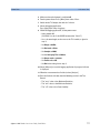
Agilent 81600B Family Tunable Laser Source Modules and
Options. . . . . . . . . . . . . . . . . . . . . . . . . . . . . . . . . . . . . . . . . . . 26
Module Options . . . . . . . . . . . . . . . . . . . . . . . . . . . . . . . . . . . 28
Options . . . . . . . . . . . . . . . . . . . . . . . . . . . . . . . . . . . . . . . . . . . . . . . 30
Connector Interfaces and Other Accessories . . . . . . . . . . . . . . 30
Option 071: Straight Contact Connector . . . . . . . . . . . . . . . . . . . 31
Option 072: Angled Contact Connector . . . . . . . . . . . . . . . . . . . . 31
Agilent 81600B Tunable Laser Source Family, Fourth Edition
25
Accessories
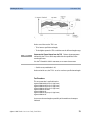
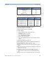
Agilent 81600B Family Tunable Laser Source Modules and Options
Agilent 81600B Family Tunable
Laser Source Modules and
Options
OPTIONAL
81600B Tunable Laser Source family
MANDATORY AND MUTUALLY EXCLUSIVE
For Laser Safety information see page 14
Tunable Laser Sources
Low SSE modules
81600B #200:
1440 nm – 1640 nm
81600B #160:
1495 nm - 1640 nm
81600B #150:
1450 nm - 1590 nm
Tunable Laser
Sources
Tunable Laser
Sources
Outputs:
Low SSE and
High Power
Outputs:
High Power
only
Tunable Laser Sources
High Power modules
81600B #142:
1370 nm - 1495 nm, + 8.5 dBm
81600B #132:
1260 nm - 1375 nm, + 9 dBm
81600B #140:
1370 nm - 1495 nm
81600B-003
with built-in
attenuator
(81600B #142 only)
81600B #130:
1260 nm - 1375 nm
81600B-071
81600B-072
PMF Straight
contact connector
PMF Angled
contact connector
Connector Interfaces
for straight connectors
2 ea required for 81600B
#200,160,150,140.
1 ea required for 81600B
#142, 132.
81000FI FC/PC
81000HI E-2000/PC
81000KI SC/PC
81000LI LC/PC
81000MI MU/PC
81000SI DIN 47256/PC
81000VI ST/PC
Connector Interface
for angled connectors
Connector Interfaces
for straight
connectors
Connector Interfaces
for angled connectors
2 ea required for 81600B
#200,160,150,140.
1 ea required for 81600B
#142, 132.
81000FI FC/APC key width 2.2mm
81000NI FC/APC key width 2.0mm
81000HI E-2000/APC
81000KI SC/APC
81000LI LC/APC
81000MI MU/APC
81000SI DIN 47256/APC
Note: 81600B - 072 is highly recommended over 81600B - 071 to reduce front-panel reflections, which will greatly reduce interference noise and
spectral ripple in the test setup.
Figure 6 Agilent 8164A/B mainframes, Agilent 81600B Family Tunable Laser Source
modules, and Options
26
Agilent 81600B Tunable Laser Source Family, Fourth Edition
Agilent 81600B Family Tunable Laser Source Modules and Options
N O TE
Accessories
Option 81600B-072 recommended Option 81600B-072 is highly
recommended over option 81600B-071 to reduce front panel reflections,
which will greatly reduce interference noise and spectral ripple in the test
setup.
Agilent 81600B Tunable Laser Source Family, Fourth Edition
27
Accessories
Module Options
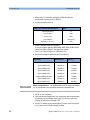
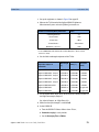
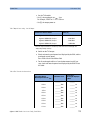
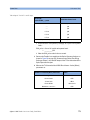
Module Options
The Agilent 8164A/B Lightwave Measurement System supports one
Agilent 81600B Family Tunable Laser Source module.
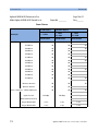
Table 1
Agilent 81600B Family Tunable Laser Source modules
Option
Description
#200
All-band Tunable Laser Source module for the test of critical DWDM
components (1440 nm - 1640 nm).
#130
Low SSE Tunable Laser Source module (1260 nm - 1375 nm).
#140
Low SSE Tunable Laser Source module (1370 nm - 1495 nm).
#150
Low SSE Tunable Laser Source module (1450 nm - 1590 nm).
#160
Low SSE Tunable Laser Source module (1495 nm - 1640 nm).
#132
High Power Tunable Laser Source module (1260 nm - 1375 nm),
+ 9 dBm.
#142
High Power Tunable Laser Source module (1370 nm - 1495 nm),
+ 8.5 dBm.
Filler Module
Table 2
Filler Module
Model No.
Agilent 81645A
Description
Filler Module
The Agilent 81645A Filler Module is required to operate the
Agilent 8164A/B mainframe if it is used without a backloadable Tunable
Laser Source module. It is used to help:
• prevent dust pollution, and
• optimize cooling by guiding the air flow.
See the "Installation and Maintenance" chapter of the Agilent 81600B
Tunable Laser Source Family User’s Guide for more details on installing the
Agilent 81645A Filler Module.
28
Agilent 81600B Tunable Laser Source Family, Fourth Edition
Module Options
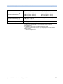
Accessories
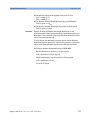
User’s Guides
Table 3
User’s Guides
Description
Part No.
Agilent 81600B Tunable Laser Source Family User’s Guide
81600-90B12
Agilent 8163A/B Lightwave Multimeter, Agilent 8164A/B Lightwave Measurement System, & Agilent 8166A/B Lightwave Multichannel System Programming Guide
08164-90B64
Agilent 8163A/B Lightwave Multimeter, Agilent 8164A/B Lightwave Measurement System, & Agilent 8166A/B Lightwave Multichannel System User’s Guide
08164-90B15
Agilent 81600B Tunable Laser Source Family, Fourth Edition
29
Accessories
Module Options
Options
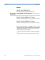
Option 003 - Agilent 81600B #142 only
Built-in optical attenuator with 60 dB attenuation range.
N O TE
Agilent 81600B #200, 160,150, and 140 have a built-in optical attenuator
as standard for Output 2, the High Power output.
Option 071 - All Agilent 81600B Family TLS modules
Polarization-maintaining fiber, Panda-type, for straight contact connectors.
Option 072 - All Agilent 81600B Family TLS modules
Polarization-maintaining fiber, Panda-type, for angled contact connectors.
Connector Interfaces and Other Accessories
The Agilent 81600B Family Tunable Laser Source modules are supplied
with one of two connector interface options:
• Option 071, Polarization-maintaining fiber straight contact connectors,
or
• Option 072, Polarization-maintaining fiber angled contact connectors.
30
Agilent 81600B Tunable Laser Source Family, Fourth Edition
Module Options
Accessories
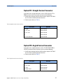
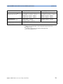
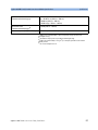
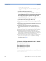
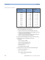
Option 071: Straight Contact Connector
If you want to use straight connectors (such as FC/PC, DIN, SC, ST or
E2000) to connect to the instrument, you must do the following:
1 Attach your connector interface to the interface adapter. See Table 4
for a list of the available connector interfaces.
2 Connect your cable (see Table 4)
Table 4 Straight Contact Connector Interfaces
Description
Model No.
DIN 47256
Agilent 81000 SI
FC / PC / SPC
Agilent 81000 FI
SC / PC / SCP
Agilent 81000 KI
ST
Agilent 81000 VI
Diamond E-2000 APC
Agilent 81000 HI
Option 072: Angled Contact Connector
If you want to use angled connectors (such as FC/APC, DIN, E2000 or
SC/APC) to connect to the instrument, you must do the following:
1 Attach your connector interface to the interface adapter. See Table 5
for a list of the available connector interfaces.
2 Connect your cable (see Table 5)
Table 5 Angled Contact Connector Interfaces
Description
Model No.
Diamond E-2000 APC
Agilent 81000 HI
SC / PC / APC
Agilent 81000 KI
FC / APC
Agilent 81000 NI
DIN 47256-4108.6
Agilent 81000 SI
Agilent 81600B Tunable Laser Source Family, Fourth Edition
31
Accessories
32
Module Options
Agilent 81600B Tunable Laser Source Family, Fourth Edition
3
Specifications
Agilent 81600B Tunable Laser Source Familys are produced to the ISO
9001 international quality system standard as part of Agilent’s
commitment to continually increasing customer satisfaction through
improved quality control.
Specifications:
Specifications apply, unless otherwise noted, for the stated environmental
conditions, after warm-up, in cw mode (unmodulated output, coherence
control off) and at uninterrupted line voltage.
Agilent 81600B Tunable Laser Source Family, Fourth Edition
33
Specifications
Definition of Terms. . . . . . . . . . . . . . . . . . . . . . . . . . . . . . . . . 35
General Definitions . . . . . . . . . . . . . . . . . . . . . . . . . . . . . . . . . . . . .36
Absolute wavelength accuracy (continuous sweep mode) . . .37
Absolute wavelength accuracy (stepped mode) . . . . . . . . . . . .37
Attenuation . . . . . . . . . . . . . . . . . . . . . . . . . . . . . . . . . . . . . . . . . . .37
Dynamic power reproducibility (continuous sweep mode) . . .38
Dynamic relative power flatness (continuous sweep mode) . .38
Effective linewidth . . . . . . . . . . . . . . . . . . . . . . . . . . . . . . . . . . . . .38
External analog modulation - modulation depth . . . . . . . . . . . .39
External digital modulation - delay time . . . . . . . . . . . . . . . . . . .39
Internal digital modulation - duty cycle . . . . . . . . . . . . . . . . . . . .39
Linewidth . . . . . . . . . . . . . . . . . . . . . . . . . . . . . . . . . . . . . . . . . . . . .40
Maximum output power. . . . . . . . . . . . . . . . . . . . . . . . . . . . . . . . .40
Mode-hop free tunability . . . . . . . . . . . . . . . . . . . . . . . . . . . . . . . .41
Operating temperature and humidity . . . . . . . . . . . . . . . . . . . . . .41
Output isolation . . . . . . . . . . . . . . . . . . . . . . . . . . . . . . . . . . . . . . . .41
Polarization extinction ratio. . . . . . . . . . . . . . . . . . . . . . . . . . . . . .42
Power flatness versus wavelength . . . . . . . . . . . . . . . . . . . . . . .42
Power linearity. . . . . . . . . . . . . . . . . . . . . . . . . . . . . . . . . . . . . . . . .43
Power repeatability. . . . . . . . . . . . . . . . . . . . . . . . . . . . . . . . . . . . .43
Power stability. . . . . . . . . . . . . . . . . . . . . . . . . . . . . . . . . . . . . . . . .44
Relative intensity noise (RIN) . . . . . . . . . . . . . . . . . . . . . . . . . . . .44
Relative wavelength accuracy (continuous sweep mode) . . . .45
Relative wavelength accuracy (stepped mode) . . . . . . . . . . . . .45
Return loss . . . . . . . . . . . . . . . . . . . . . . . . . . . . . . . . . . . . . . . . . . . .46
Side-mode suppression ratio. . . . . . . . . . . . . . . . . . . . . . . . . . . . .46
Signal to source spontaneous emission (SSE) ratio . . . . . . . . .46
Signal to total source spontaneous emission ratio . . . . . . . . . .47
Wavelength range . . . . . . . . . . . . . . . . . . . . . . . . . . . . . . . . . . . . . .48
Wavelength repeatability (continuous sweep mode) . . . . . . . .48
Wavelength repeatability (stepped mode) . . . . . . . . . . . . . . . . .49
Wavelength resolution . . . . . . . . . . . . . . . . . . . . . . . . . . . . . . . . . .49
Wavelength stability. . . . . . . . . . . . . . . . . . . . . . . . . . . . . . . . . . . .50
Agilent 81600B Family Tunable Laser Source Module
Specifications . . . . . . . . . . . . . . . . . . . . . . . . . . . . . . . . . . . . . 51
Conditions . . . . . . . . . . . . . . . . . . . . . . . . . . . . . . . . . . . . . . . . 66
Supplementary Performance Characteristics . . . . . . . . . . . . . . .68
General . . . . . . . . . . . . . . . . . . . . . . . . . . . . . . . . . . . . . . . . . . . . . . .69
34
Agilent 81600B Tunable Laser Source Family, Fourth Edition
Definition of Terms
Specifications
Definition of Terms
This section defines terms that are used both in this chapter and in
Chapter 4, “Performance Tests.
Measurement principles are indicated. Alternative measurement
principles of equal value are also acceptable.
Agilent 81600B Tunable Laser Source Family, Fourth Edition
35
Specifications
Definition of Terms
General Definitions
Attenuation mode
An operation mode where the output power is adjusted using the built-in
attenator, rather than by changing the current of the laser diode.
N O TE
Applicable only to
in attenator.
Tunable Laser Source modules that include a built-
Constant Temperature
Where required, is a stable operating temperature within ±1 K.
Logged wavelength
This is the wavelength measured and recorded by the internal wavelength
meter during a sweep at the corresponding trigger signal. This recorded
wavelength can be read with the logging function.
N O TE
The logged wavelength positions during a sweep depend on
environmental conditions and may differ slightly between repeated
sweeps.
Stepped mode
In stepped mode the tunable laser source is operated statically, so that a
user's measurement is made at a fixed wavelength of the tunable laser
source. When tuning to a new wavelength, the static specifications are
valid after completion of the tuning operation.
Continuous sweep mode
In continuous sweep mode the tunable laser source is operated
dynamically, so that a user's measurement is made while the wavelength
of the tunable laser source changes in a defined way (given by start
wavelength, end wavelength and sweep speed). During a continuous
sweep the dynamic specifications and the “Logged wavelength” applies.
36
Agilent 81600B Tunable Laser Source Family, Fourth Edition
Definition of Terms
Specifications
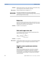
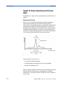
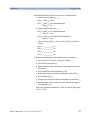
Absolute wavelength accuracy (continuous
sweep mode)
The maximum difference between the “Logged wavelength” and the
actual wavelength in “Continuous sweep mode”. Wavelength is defined
as wavelength in vacuum.
Figure 7 Absolute wavelength accuracy (continuous sweep mode)
Conditions:
As specified. No mode-hop.
Absolute wavelength accuracy (stepped
mode)
The maximum difference between the displayed wavelength and the
actual wavelength of the tunable lase source. Wavelength is defined as
wavelength in vacuum.
Conditions:
Measurement:
N O TE
Constant power level. Other conditions as specified.
Using a wavelength meter, averaging time ≥ 1 s.
The absolute wavelength accuracy of the low-SSE output
(if applicable) is the same as the absolute wavelength accuracy of the high
power output (guaranteed by design).
Attenuation
The nominal attenuation of the output power selected using the built-in
attenuator.
N O TE
Applicable only to
in attenator.
Agilent 81600B Tunable Laser Source Family, Fourth Edition
Tunable Laser Source modules that include a built-
37
Specifications
Definition of Terms
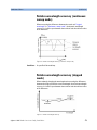
Dynamic power reproducibility (continuous
sweep mode)
Specifies the random uncertainty in reproducing the output power at the
same actual wavelength in different sweeps. It is expressed as ± half the
span between the maximum and minimum of all actual output powers.
Figure 8 Dynamic power reproducibility (continuous sweep mode)
Conditions:
Uninterrupted tunable laser source output power, constant temperature,
no mode-hop. Other conditions as specified.
Dynamic relative power flatness
(continuous sweep mode)
The high frequency part of the dynamic power flatness, obtainable by
referencing the power measured at high sweep speed to the power
measured at low sweep speed.
Conditions:
Measurement:
Uninterrupted tunable laser source output power, constant power setting,
constant temperature, no mode-hop. Other conditions as specified.
Reference sweep speed value 0.5 nm/s.
Effective linewidth
The time-averaged 3 dB width of the optical spectrum, expressed in Hertz.
Conditions:
Measurement:
38
Coherence control on. Other conditions as specified.
Using a heterodyning technique: The output of the laser under test is
mixed with another laser of the same type on a wide bandwidth
photodetector. The electrical noise spectrum of the photodetector current
is measured with an Agilent Lightwave signal analyzer, and the linewidth
calculated from the heterodyne spectrum. (Lightwave signal analyzer
settings: resolution bandwidth 1 MHz, video bandwidth 10 kHz,
sweep time 20 ms, single scan).
Agilent 81600B Tunable Laser Source Family, Fourth Edition
Definition of Terms
Specifications
External analog modulation - modulation
depth
Specifies half the peak-to-peak optical power change divided by the
average optical power for a sinusoidal input voltage at the analog
modulation input. The average power is defined as half the sum of
maximum and minimum power.
Conditions:
N O TE
Measurement:
Modulation input signal as specified, modulation frequency as specified.
Modulation depth
is a is a value between 0 and 100%
Using a photoreceiver (of sufficient bandwidth) and an oscilloscope.
External digital modulation - delay time
Specifies the time between the falling edge of the external trigger (when
reaching logical zero) and the falling edge of the optical pulse (at 10% of its
original value).
Conditions:
Measurement:
Modulation input signal and duty cycle as specified, modulation frequency
as specified.
Using a photoreceiver (of sufficient bandwidth) and an oscilloscope.
Internal digital modulation - duty cycle
When the laser is internally (digitally) modulated at a
frequency f, the duty cycle is specified as τon x f,
where τon is the time the laser is on during one modulation cycle
(expressed in percent).
Conditions:
Modulation frequency as specified.
Agilent 81600B Tunable Laser Source Family, Fourth Edition
39
Specifications
Definition of Terms
Linewidth
The 3 dB width of the optical spectrum, expressed in Hertz.
Conditions:
Measurement:
Coherence control off. Other conditions as specified.
Using a self-heterodyning technique: The output of the laser under test is
sent through a Mach-Zehnder interferometer in which the length
difference of the two arms is longer than the coherence length of the laser.
The electrical noise spectrum of the photodetector current is measured
using an
Agilent Lightwave signal analyzer, and the linewidth calculated from the
heterodyne spectrum.
Alternatively, Using a heterodyning technique: The output of the laser
under test is mixed with another laser of the same type on a wide
bandwidth photodetector. The electrical noise spectrum of the
photodetector current is measured using an Agilent Lightwave signal
analyzer, and the linewidth calculated from the heterodyne spectrum.
(Lightwave signal analyzer settings:
resolution bandwidth 1 MHz, video bandwidth 10 kHz,
sweep time 20 ms, single scan).
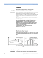
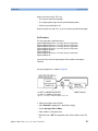
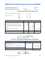
Maximum output power
The maximum achievable output power of the tunable laser source and the
maximum output power for which the tunable laser source specifications
apply.
Figure 9 Maximum Output Power vs Wavelength, Maximum Flat Output Power vs Wavelength
Conditions:
Measurement:
40
As specified.
Using a power meter at the end of a 2 m single-mode fiber patchcord.
Agilent 81600B Tunable Laser Source Family, Fourth Edition
Definition of Terms
Specifications
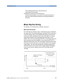
Mode-hop free tunability
Specifies the wavelength range for which no abrupt wavelength change
occurs in “Stepped mode”. Abrupt change is defined as change of more
than the specified “Absolute wavelength accuracy (stepped mode)”.
Operating temperature and humidity
The ambient temperature range and humidity range of the tunable laser
source for which the specifications apply.
N O TE
If the optical mainframe hosting the tunable laser source module is
rack-mounted the temperature and humidity within the rack apply.
Output isolation
The insertion loss of the built-in isolator in the backward direction.
Measurement:
This characteristic cannot be measured from outside the module. It is
based on known isolator characteristics.
Agilent 81600B Tunable Laser Source Family, Fourth Edition
41
Specifications
Definition of Terms
Polarization extinction ratio
Specifies the ratio of the optical power in the slow axis of a connected
polarization-maintaining fiber to optical power in the fast axis, expressed
in dB
N O TE
Measurement:
Applicable to tunable laser sources Utilizing polarization maintaining
fiber (TE mode in the slow axis and aligned with the connector key).
Using a polarization analyzer at the end of a polarization-maintaining
patchcord, by sweeping the wavelength to create circular traces on the
Poincaré sphere. Calculate the polarization extinction ratio from the
diameters of these circles.
Figure 10 Circular traces on the Poincaré sphere used to calculate polarization extinction
ratio.
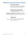
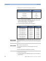
Power flatness versus wavelength
Specifies ± half the span (in dB) between the maximum and the minimum
actual power levels of the tunable laser source when changing the
wavelength.
Figure 11 Power flatness vs. wavelength.
42
Agilent 81600B Tunable Laser Source Family, Fourth Edition
Definition of Terms
Specifications
Conditions:
Uninterrupted tunable laser source output power, constant power setting,
constant temperature. Other conditions as specified.
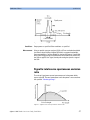
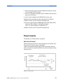
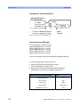
Power linearity
When measuring the ratios (in dB) between the displayed power level and
the actual power level for different output power levels of the tunable laser
source, the power linearity is ± half the difference between the maximum
and the minimum value of all ratios.
Figure 12 Power linearity.
Conditions:
Uninterrupted tunable laser source output power, constant wavelength
setting, constant temperature. Other conditions as specified.
Power repeatability
The uncertainty in reproducing the power level after changing and resetting the power level. The power repeatability is ± half the span
between the highest and lowest actual power.
Conditions:
N O TE
Uninterrupted tunable laser source output power, constant wavelength
setting, constant temperature. Other conditions as specified.
The long-term power repeatability can be obtained by taking the
power repeatability and power stability into account.
Agilent 81600B Tunable Laser Source Family, Fourth Edition
43
Specifications
Definition of Terms
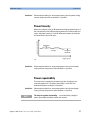
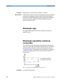
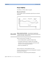
Power stability
Specifies the change of the power level of the tunable laser source over
time, expressed as ± half the span (in dB) between the highest and lowest
actual power.
Figure 13 Power stability.
Conditions:
Time span as specified. Uninterrupted tunable laser source output power,
constant wavelength and power level settings, constant temperature.
Other conditions as specified.
Relative intensity noise (RIN)
Specifies the ratio between the mean-square of the optical power
fluctuation amplitude ∆Pf,B within a specified frequency range f and for
bandwidth B, and the square of the average optical power Pavg.
RIN, if expressed as "dB/Hz", is calculated by:
Conditions:
Measurement:
44
As specified.
Using an Agilent Lightwave signal analyzer and bandwidth set to 3 MHz.
Agilent 81600B Tunable Laser Source Family, Fourth Edition
Definition of Terms
Specifications
Relative wavelength accuracy (continuous
sweep mode)
When measuring the differences between the actual and “Logged
wavelength” in “Continuous sweep mode”, the dynamic wavelength
accuracy is ± half the span between the maximum and the minimum value
of all differences.
Figure 14 Relative wavelength accuracy (continuous sweep mode).
Conditions:
As specified. No mode-hop.
Relative wavelength accuracy (stepped
mode)
When randomly changing the wavelength and measuring the differences
between the displayed and the actual wavelength, the relative wavelength
accuracy is ± half the span between the maximum and the minimum value
of all differences.
Figure 15 Relative wavelength accuracy.
Agilent 81600B Tunable Laser Source Family, Fourth Edition
45
Specifications
Definition of Terms
Conditions:
Measurement:
N O TE
Uninterrupted tunable laser source output power, constant power setting,
constant temperature. Other conditions as specified.
Using a wavelength meter, averaging time ≥ 1 s.
The relative wavelength accuracy of the low-SSE output
(if applicable) is the same as the relative wavelength accuracy of the high
power output (guaranteed by design).
Return loss
Specifies the ratio of the optical power incident to the tunable laser source
output port at the wavelength set on the tunable laser source, to the power
reflected from the tunable laser source output port.
Conditions:
Tunable laser source output off.
Side-mode suppression ratio
The ratio of optical power in the main mode to the optical power of the
highest sidemode, expressed in dB:
Conditions:
Measurement:
As specified.
Using the Agilent Lightwave signal analyzer, by analyzing the heterodyning
between the main signal and the highest sidemode within 0.1 GHz to
6 GHz.
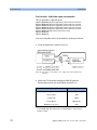
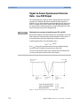
Signal to source spontaneous emission
(SSE) ratio
Specifies the ratio between signal power and maximum spontaneous
emission (SSE) power. The SSE power is determined in a specified
bandwidth within a ±3 nm window around the signal wavelength, where
±1 nm around the signal wavelength are excluded, expressed in dB per
specified bandwidth.
46
Agilent 81600B Tunable Laser Source Family, Fourth Edition
Definition of Terms
Specifications
Figure 16 Signal to source spontaneous emission ratio.
Conditions:
Measurement:
Output power as specified. Other contitions as specified.
Using an optical spectrum analyzer (OSA) at 0.5 nm resolution bandwidth
(to address the possibility of higher SSE within a narrower bandwidth),
then extrapolated to 1 nm bandwidth. For the low-SSE output, if applicable,
with a fiber Bragg grating inserted between the tunable laser source and
the OSA to suppress the signal, thereby enhancing the dynamic range of
the OSA.
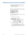
Signal to total source spontaneous emission
ratio
The ratio of signal power to total spontaneous emission power within,
expressed in dB. The total spontaneous emission power is measured over
the specified “Wavelength range”.
Figure 17 Signal to total source spontaneous emission ratio.
Agilent 81600B Tunable Laser Source Family, Fourth Edition
47
Specifications
Definition of Terms
Conditions:
Measurement:
Output power as specified. Other conditions as specified.
Using an optical spectrum analyzer, by integrating the source spontaneous
emission and excluding the remnant signal. For the low-SSE output, if
applicable, with a fiber Bragg grating inserted between the tunable laser
source and the OSA to suppress the signal, thereby enhancing the
dynamic range of the OSA.
Mea surement principles are indica ted. Alternativ e measurem ent principles of equal va lue are also accepta ble.
Wavelength range
The range of wavelengths for which the specifications apply (if not
otherwise stated).
Wavelength repeatability (continuous
sweep mode)
The random uncertainty of the nominal wavelength of the tunable laser
source at any fixed actual wavelength in repeated sweeps. The nominal
wavelength of the tunable laser source is derived from the (discrete)
“Logged wavelength”s by interpolation. The repeatability is expressed as
± half the span between the maximum and the minimum value of all
nominal values.
Figure 18 Wavelength repeatability (continuous sweep mode).
Conditions:
48
As specified. No mode-hop.
Agilent 81600B Tunable Laser Source Family, Fourth Edition
Definition of Terms
Specifications
Measurement:
Using an optical powermeter and by performing repeated spectral loss
measurement on a stable absorption peak from a reference component,
then analyzing the variation of the determined (interpolated) wavelength of
the peak.
Wavelength repeatability (stepped mode)
The random uncertainty in reproducing a wavelength after changing and
re-setting the wavelength. The wavelength repeatability is ± half the span
between the maximum and the minimum of all actual values of this
wavelength.
Conditions:
Measurement:
N O TE
N O TE
Uninterrupted tunable laser source output power, constant power level,
constant temperature. Other conditions as specified.
Using a wavelength meter, averaging time ≥ 1 s.
The wavelength repeatability of the low-SSE output
(if applicable) is the same as the wavelength repeatability of the high
power output (guaranteed by design).
The long-term wavelength repeatability can be obtained by taking
the wavelength repeatability and wavelength stability into account.
Wavelength resolution
The smallest selectable wavelength increment or decrement.
Agilent 81600B Tunable Laser Source Family, Fourth Edition
49
Specifications
Definition of Terms
Wavelength stability
Specifies the change of the actual wavelength of the tunable laser source
over time, expressed as ± half the span between the maximum and
minimum of all wavelengths.
Conditions:
Measurement:
Time span as specified, uninterrupted tunable laser source output power,
constant wavelength and power level settings, constant temperature.
Other conditions as specified.
Using a wavelength meter, averaging time ≥ 1 s.
Mea surement principles are indica ted. Alternativ e measurem ent principles of equal va lue are also accepta ble.
50
Agilent 81600B Tunable Laser Source Family, Fourth Edition
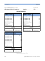
Agilent 81600B Family Tunable Laser Source Module Specifications
Specifications
Agilent 81600B Family Tunable
Laser Source Module
Specifications
81600B opt. 200 All-band TLS module, 1440 nm - 1640 nm, low
SSE . . . . . . . . . . . . . . . . . . . . . . . . . . . . . . . . . . . . . . . . . . . . . . . . . . 52
81600B opt. 160 TLS module, 1495 nm - 1640 nm, low SSE . . 54
81600B opt. 150 TLS module, 1450 nm - 1590 nm, low SSE . . 56
81600B opt. 140 TLS module, 1370 nm - 1495 nm, low SSE . . 58
81600B opt. 130 TLS module, 1260 nm - 1375 nm, low SSE . . 60
81600B opt.142 TLS module, 1370 nm - 1495 nm, high power 62
81600B opt.132 TLS module, 1260 nm - 1375 nm, high power 64
Conditions . . . . . . . . . . . . . . . . . . . . . . . . . . . . . . . . . . . . . . . . 66
Supplementary Performance Characteristics. . . . . . . . . . . . . . . 68
General . . . . . . . . . . . . . . . . . . . . . . . . . . . . . . . . . . . . . . . . . . . . . . . 69
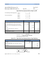
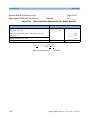
Specifications:
Describe guaranteed product performance that is valid under stated
conditions. The confidence level is 95%, as recommended by the ISO
standard.
Typical Values and Supplementary Performance Characteristics:
Describe product performance that is usually met but not guaranteed.
Because of the modular nature of the instrument, these performance
specifications apply to these modules rather than the mainframe unit.
Agilent 81600B Tunable Laser Source Family, Fourth Edition
51
Specifications
Agilent 81600B Family Tunable Laser Source Module Specifications
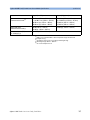
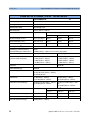
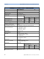
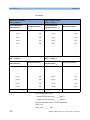
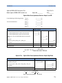
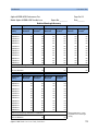
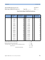
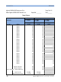
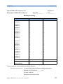
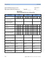
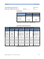
81600B opt. 200 All-band TLS module, 1440 nm - 1640 nm, low SSE
Agilent 81600B opt.200
Wavelength range
1440 nm to 1640 nm
Wavelength resolution
0.1 pm, 12.5 MHz at 1550 nm
Mode-hop free tunability
full wavelength range
Max. sweep speed
80 nm/s
Stepped mode
2.3
Continuous sweep mode (typ.)
at 5 nm/s
at 40 nm/s
at 80 nm/s
±10 pm, typ. ±3.6 pm ±4.0 pm
±4.6 pm
±6.1 pm
Relative wavelength accuracy [1]
±5 pm, typ. ±2 pm
±2.4 pm
±2.8 pm
±4.0 pm
Wavelength repeatability
±0.8 pm, typ. ±0.5 pm ±0.3 pm
±0.4 pm
±0.7 pm
Wavelength stability [4] (typ.)
≤ ±1 pm, 24 hours
Linewidth (typ.), coherence control off
Effective linewidth (typ.), coherence ctrl.
on
100 kHz
> 50 MHz (1475 nm – 1625 nm, at max. constant output power)
Absolute wavelength accuracy
[1]
Maximum output power
(continuous power during sweep)
Output 1 (low SSE)
Output 2 (high power)
≥ +3 dBm peak typ.
≥ +2 dBm (1520 nm – 1610 nm)
≥ -2 dBm (1475 nm – 1625 nm)
≥ -7 dBm (1440 nm – 1640 nm)
≥ +9 dBm peak typ.
≥ +8 dBm (1520 nm – 1610 nm)
≥ +4 dBm (1475 nm – 1625 nm)
≥ -1 dBm (1440 nm – 1640 nm)
Attenuation
max. 60 dB
Power repeatability (typ.)
±0.003 dB
Power stability [4]
±0.01 dB, 1 hour
typ. ±0.03 dB, 24 hours
Power linearity
±0.1 dB
±0.1 dB
(±0.3 dB in attenuation mode)
Power flatness versus wavelength
±0.25 dB [3] typ. ±0.1 dB
±0.3 dB [3] typ. ±0.15 dB
Continuous sweep mode
at 5 nm/s
at 40 nm/s
at 80 nm/s
Dynamic power reproducibility (typ.)
±0.005 mB
±0.01 dB
±0.015 dB
Dynamic relative power flatness (typ.)
±0.01 dB
±0.02 dB
±0.04 dB
Side-mode suppression ratio (typ.)
52
≥ 60 dB (1520 nm – 1610 nm)
Agilent 81600B Tunable Laser Source Family, Fourth Edition
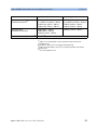
Agilent 81600B Family Tunable Laser Source Module Specifications
Specifications
Output 1 (low SSE)
Output 2 (high power)
Signal to source
spontaneous emission ratio [2]
≥ 70 dB/nm (1520 nm – 1610 nm)
typ. ≥ 80 dB/0.1 nm (1520 nm – 1610 nm)
≥ 66 dB/nm (typ., 1475 nm – 1625 nm)
≥ 60 dB/nm (typ., 1440 nm – 1640 nm)
≥ 48 dB/nm (1520 nm – 1610 nm)
typ.≥ 58 dB/0.1nm (1520 nm – 1610 nm)
≥ 43 dB/nm (1475 nm – 1625 nm)
≥ 37 dB/nm (1440 nm – 1640 nm)
Signal to total source
spontaneous emission ratio [2]
≥ 65 dB (1520 nm – 1610 nm)
≥ 57 dB (typ., 1440 nm – 1640 nm)
≥ 30 dB (typ., 1520 nm – 1610 nm)
Relative intensity noise (RIN)
(0.1 – 6 GHz) (typ.) [2]
-145 dB/Hz (1520 nm – 1610 nm)
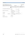
[1]
Valid for one month and within a ±4.4 K temperature range after automatic
wavelength zeroing.
[2] At maximum output power as specified per wavelength range.
[3]
Wavelength range 1440 nm – 1630 nm.
[4] At constant temperature ±1 K
Agilent 81600B Tunable Laser Source Family, Fourth Edition
53
Specifications
Agilent 81600B Family Tunable Laser Source Module Specifications
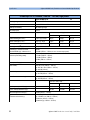
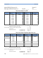
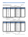
81600B opt. 160 TLS module, 1495 nm - 1640 nm, low SSE
Agilent 81600B opt.160
2.3
Wavelength range
1495 nm to 1640 nm
Wavelength resolution
0.1 pm, 12.5 MHz at 1550 nm
Mode-hop free tunability
full wavelength range
Max. sweep speed
80 nm/s
Stepped mode
Continuous sweep mode (typ.)
at 5 nm/s
at 40 nm/s
at 80 nm/s
±10 pm, typ. ±3.6 pm
±4.0 pm
±4.6 pm
±6.1 pm
Relative wavelength accuracy [1]
±5 pm, typ. ±2 pm
±2.4 pm
±2.8 pm
±4.0 pm
Wavelength repeatability
±0.8 pm, typ. ±0.5 pm
±0.3 pm
±0.4 pm
±0.7 pm
Wavelength stability [3] (typ.)
≤ ±1 pm, 24 hours
Absolute wavelength accuracy
[1]
Linewidth (typ.), coherence control off
100 kHz
Effective linewidth (typ.), coherence ctrl. > 50 MHz (1510 nm – 1620 nm, at max. constant output power)
on
Maximum output power
(continuous power during sweep)
Output 1 (low SSE)
Output 2 (high power)
≥ -2 dBm peak typ.
≥ -4 dBm (1520 nm – 1610 nm)
≥ -6 dBm (1510 nm – 1620 nm)
≥ -7 dBm (1495 nm – 1640 nm)
≥ +7 dBm peak typ.
≥ +5 dBm (1520 nm – 1610 nm)
≥ +3 dBm (1510 nm – 1620 nm)
≥ -1 dBm (1495 nm – 1640 nm)
Attenuation
max. 60 dB
Power repeatability (typ.)
±0.003 dB
Power stability [3]
±0.01 dB, 1 hour
typ. ±0.03 dB, 24 hours
Power linearity
±0.1 dB
±0.1 dB
(±0.3 dB in attenuation mode)
Power flatness versus wavelength
±0.25 dB, typ. ±0.1 dB (1495 nm – 1630 nm)
±0.3 dB, typ. ±0.15 dB
Continuous sweep mode
at 5 nm/s
at 40 nm/s
at 80 nm/s
Dynamic power reproducibility (typ.)
±0.005 mB
±0.01 dB
±0.015 dB
Dynamic relative power flatness (typ.)
±0.01 dB
±0.02 dB
±0.04 dB
Side-mode suppression ratio (typ.) [2]
54
≥ 40 dB (1520 nm – 1610 nm)
Agilent 81600B Tunable Laser Source Family, Fourth Edition
Agilent 81600B Family Tunable Laser Source Module Specifications
Specifications
Output 1 (low SSE)
Output 2 (high power)
Signal to source
spontaneous emission ratio [2]
≥ 64 dB/nm (1520 nm – 1610 nm)
typ. ≥ 74 dB/0.1 nm (1520 nm – 1610 nm)
≥ 62 dB/nm (typ., 1510 nm – 1620 nm)
≥ 59 dB/nm (typ., 1495 nm – 1640 nm)
≥ 45 dB/nm (1520 nm – 1610 nm)
typ. ≥55 dB/0.1nm (1520 nm – 1610 nm)
≥ 42 dB/nm (1510 nm – 1620 nm)
≥ 37 dB/nm (1495 nm – 1640 nm)
Signal to total source
spontaneous emission ratio [2]
≥ 59 dB (1520 nm – 1610 nm)
≥ 56 dB (typ., 1495 nm – 1640 nm)
≥ 27 dB (typ., 1520 nm – 1610 nm)
Relative intensity noise (RIN)
(0.1 – 6 GHz) (typ.) [2]
-145 dB/Hz (1520 nm – 1610 nm)
[1]
Valid for one month and within a ±4.4 K temperature range after automatic
wavelength zeroing.
[2] At maximum output power as specified per wavelength range.
[3]
At constant temperature ±1 K
Agilent 81600B Tunable Laser Source Family, Fourth Edition
55
Specifications
Agilent 81600B Family Tunable Laser Source Module Specifications
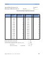
81600B opt. 150 TLS module, 1450 nm - 1590 nm, low SSE
Agilent 81600B opt.150
2.3
Wavelength range
1450 nm to 1590 nm
Wavelength resolution
0.1 pm, 12.5 MHz at 1550 nm
Mode-hop free tunability
full wavelength range
Max. sweep speed
80 nm/s
Stepped mode
Continuous sweep mode (typ.)
at 5 nm/s
at 40 nm/s
at 80 nm/s
±10 pm, typ. ±3.6 pm
±4.0 pm
±4.6 pm
±6.1 pm
Relative wavelength accuracy [1]
±5 pm, typ. ±2 pm
±2.4 pm
±2.8 pm
±4.0 pm
Wavelength repeatability
±0.8 pm, typ. ±0.5 pm
±0.3 pm
±0.4 pm
±0.7 pm
Wavelength stability [3] (typ.)
≤ ±1 pm, 24 hours
Absolute wavelength accuracy
[1]
Linewidth (typ.), coherence control off
100 kHz
Effect. linewidth (typ.), coherence ctrl. on > 50 MHz (1480 nm – 1580 nm, at max. constant output power)
Maximum output power
(continuous power during sweep)
Output 1 (low SSE)
Output 2 (high power)
≥ -1 dBm peak typ.
≥ -3 dBm (1520 nm – 1570 nm)
≥ -6 dBm (1480 nm – 1580 nm)
≥ -7 dBm (1450 nm – 1590 nm)
≥ +7 dBm peak typ.
≥ +5 dBm (1520 nm – 1570 nm)
≥ +4 dBm (1480 nm – 1580 nm)
≥ -1 dBm (1450 nm – 1590 nm)
Attenuation
max. 60 dB
Power repeatability (typ.)
±0.003 dB
Power stability [3]
±0.01 dB, 1 hour
typ. ±0.03 dB, 24 hours
Power linearity
±0.1 dB
±0.1 dB
(±0.3 dB in attenuation mode)
Power flatness versus wavelength
±0.2 dB, typ. ±0.1 dB
±0.3 dB, typ. ±0.15 dB
Continuous sweep mode
at 5 nm/s
at 40 nm/s
at 80 nm/s
Dynamic power reproducibility (typ.)
±0.005 mB
±0.01 dB
±0.015 dB
Dynamic relative power flatness (typ.)
±0.01 dB
±0.02 dB
±0.04 dB
Side-mode suppression ratio (typ.) [2]
56
≥ 40 dB (1480 nm – 1580 nm)
Agilent 81600B Tunable Laser Source Family, Fourth Edition
Agilent 81600B Family Tunable Laser Source Module Specifications
Specifications
Output 1 (low SSE)
Output 2 (high power)
Signal to source
spontaneous emission ratio [2]
≥ 65 dB/nm (1520 nm – 1570 nm)
typ. ≥ 75 dB/0.1 nm (1520 nm – 1570 nm)
≥ 61 dB/nm (typ., 1480 nm – 1580 nm)
≥ 59 dB/nm (typ., 1450 nm – 1590 nm)
≥45 dB/nm (1520 nm – 1570 nm)
typ. ≥ 55 dB/0.1nm (1520 nm – 1570 nm)
≥ 42 dB/nm (1480 nm – 1580 nm)
≥ 37 dB/nm (1450 nm – 1590 nm)
Signal to total source
spontaneous emission ratio [2]
≥ 60 dB (1520 nm – 1570 nm)
≥ 50 dB (typ., 1450 nm – 1590 nm)
≥ 30 dB (typ., 1520 nm – 1570 nm)
Relative intensity noise (RIN)
(0.1 – 6 GHz) (typ.) [2]
-145 dB/Hz (1480 nm – 1580 nm)
[1] Valid for one month and within a ±4.4
K temperature range after automatic
wavelength zeroing.
[2] At maximum output power as specified per wavelength range.
[3] At constant temperature ±1 K
Agilent 81600B Tunable Laser Source Family, Fourth Edition
57
Specifications
Agilent 81600B Family Tunable Laser Source Module Specifications
81600B opt. 140 TLS module, 1370 nm - 1495 nm, low SSE
Agilent 81600B opt.140
2.4
Wavelength range
1370 nm to 1495 nm
Wavelength resolution
0.1 pm, 15 MHz at 1450 nm
Mode-hop free tunability
full wavelength range
Max. sweep speed
80 nm/s (1372 nm – 1495 nm)
Stepped mode
Continuous sweep mode (typ.)
at 5 nm/s
at 40 nm/s
at 80 nm/s
±10 pm, typ. ±3.6 pm
±4.0 pm
±4.6 pm
±6.1 pm
Relative wavelength accuracy [1]
±5 pm, typ. ±2 pm
±2.4 pm
±2.8 pm
±4.0 pm
Wavelength repeatability
±0.8 pm, typ. ±0.5 pm ±0.3 pm
±0.4 pm
±0.7 pm
Wavelength stability [4] (typ.)
≤ ±1 pm, 24 hours
Linewidth (typ.), coherence control off
Effective linewidth (typ.), coherence ctrl. on
100 kHz
> 50 MHz (1430 nm – 1480 nm, at max. constant output power)
Absolute wavelength accuracy
[1]
Maximum output power
(continuous power during sweep)
Output 1 (low SSE)
Output 2 (high power)
≥ -4.5 dBm peak typ.
≥ -5 dBm (1430 nm – 1480 nm)
≥ -7 dBm (1420 nm – 1480 nm)
≥ -13 dBm (1370 nm – 1495 nm)
≥+5.5 dBm peak typ.
≥ +5 dBm (1430 nm – 1480 nm)
≥ +3 dBm (1420 nm – 1480 nm)
≥ -3 dBm (1370 nm – 1495 nm)
Attenuation
max. 60 dB
Power repeatability (typ.)
±0.003 dB
Power stability [4]
±0.01 dB, 1 hour (1420 nm – 1495 nm)
typ. ±0.01 dB, 1 hour (1370 nm – 1420 nm)
typ. ±0.03 dB, 24 hours
Power linearity
±0.1 dB (1420 nm – 1495 nm)
typ. ±0.1 dB (1370 nm – 1420 nm)
±0.3 dB (1420 nm – 1495 nm)
typ. ±0.3 dB (1370 nm – 1420 nm)
Power flatness versus wavelength
±0.2 dB, typ. ±0.1 dB (1420 nm – 1495 nm)
typ. ±0.2 dB (1370 nm – 1420 nm)
±0.3 dB, typ. ±0.2 dB (1420 nm – 1495
nm)
typ. ±0.3 dB (1370 nm – 1420 nm)
Continuous sweep mode [3]
at 5 nm/s
at 40 nm/s
at 80 nm/s
Dynamic power reproducibility (typ.)
±0.005 mB
±0.01 dB
±0.015 dB
Dynamic relative power flatness (typ.)
±0.01 dB
±0.015dB
±0.03 dB
Side-mode suppression ratio (typ.)
58
[2]
≥ 40 dB (1430 nm – 1480 nm)
Agilent 81600B Tunable Laser Source Family, Fourth Edition
Agilent 81600B Family Tunable Laser Source Module Specifications
Specifications
Output 1 (low SSE)
Output 2 (high power)
Signal to source
spontaneous emission ratio [2]
≥ 63 dB/nm (1430 nm – 1480 nm)
typ. ≥ 73 dB/0.1 nm (1430 nm – 1480 nm)
≥ 61 dB/nm (typ., 1420 nm – 1480 nm)
≥ 55 dB/nm (typ., 1370 nm – 1495 nm)
≥ 42 dB/nm (1430 nm – 1480 nm)
typ. ≥ 52 dB/0.1nm (1430 nm – 1480 nm)
≥ 40 dB/nm (1420 nm – 1480 nm)
≥ 35 dB/nm (1370 nm – 1495 nm)
Signal to total source
spontaneous emission ratio [2]
≥ 60 dB (1430 nm – 1480 nm)
≥ 58 dB (1420 nm – 1480 nm)
≥ 53 dB (typ., 1370 nm – 1495 nm)
≥ 28 dB (typ., 1430 nm – 1480 nm)
Relative intensity noise (RIN) (0.1 – 6 GHz) [2] -145 dB/Hz [1] (typ., 1430 nm – 1480 nm)
[1] Valid for one month and within a ±4.4 K temperature range after automatic
wavelength zeroing.
[2]
At maximum output power as specified per wavelength range.
[3] Valid for absolute humidity of 11.5 g/m3 (For example, equivalent to 50% relative
humidity at 25° C
[4] At constant temperature ±1 K
Agilent 81600B Tunable Laser Source Family, Fourth Edition
59
Specifications
Agilent 81600B Family Tunable Laser Source Module Specifications
81600B opt. 130 TLS module, 1260 nm - 1375 nm, low SSE
Agilent 81600B opt.130
1.0
Wavelength range
1260 nm to 1375 nm
Wavelength resolution
0.1 pm, 17.7 MHz at 1300 nm
Mode-hop free tunability
full wavelength range
Max. sweep speed
80 nm/s
Stepped mode
Continuous sweep mode (typ.)
at 5 nm/s
at 40 nm/s
at 80 nm/s
±10 pm, typ. ±3.6 pm
±4.0 pm
±4.6 pm
±6.1 pm
Relative wavelength accuracy [1]
±5 pm, typ. ±2 pm
±2.4 pm
±2.8 pm
±4.0 pm
Wavelength repeatability
±0.8 pm, typ. ±0.5 pm
±0.3 pm
±0.4 pm
±0.7 pm
Wavelength stability [4] (typ.)
≤ ±1 pm, 24 hours
Linewidth (typ.), coherence control off
Effect. linewidth (typ.), coherence ctrl. on
100 kHz
> 50 MHz (1270 nm – 1350 nm, at max. constant output power)
Absolute wavelength accuracy
[1]
Maximum output power
(continuous power during sweep)
Output 1 (low SSE)
Output 2 (high power)
≥ -4 dBm peak typ.
≥ -6 dBm (1290 nm – 1370 nm)
≥ -9 dBm (1270 nm – 1375 nm)
≥ -13 dBm (1260 nm – 1375 nm)
≥ +5 dBm peak (typ.)
≥ +4 dBm (1290 nm – 1370 nm)
≥ +1 dBm (1270 nm – 1375 nm)
≥ -3 dBm (1260 nm – 1375 nm)
Attenuation
max. 60 dB
Power repeatability (typ.)
±0.003 dB
Power stability [4]
±0.01 dB, 1 hour (1260 nm – 1350 nm)
typ. ±0.01 dB, 1 hour (1350 nm – 1375 nm)
typ. ±0.03 dB, 24 hours
Power linearity
±0.1 dB (1260 nm – 1350 nm)
typ. ±0.1 dB (1350 nm – 1375 nm)
±0.3 dB (1260 nm – 1350 nm)
typ. ±0.3 dB (1350 nm – 1375 nm)
Power flatness versus wavelength
±0.2 dB, typ. ±0.1 dB (1260 nm – 1350 nm)
typ. ±0.2 dB (1350 nm – 1375 nm)
±0.3 dB, typ. ±0.2 dB (1260 nm – 1350 nm)
typ. ±0.3 dB (1350 nm – 1375 nm)
Continuous sweep mode [3]
at 5 nm/s
at 40 nm/s
at 80 nm/s
Dynamic power reproducibility (typ.)
±0.005 mB
±0.01 dB
±0.015 dB
Dynamic relative power flatness (typ.)
±0.01 dB
±0.02 5dB
±0.04 dB
Side-mode suppression ratio (typ.)
60
[2]
≥ 40 dB (1290 nm – 1370 nm)
Agilent 81600B Tunable Laser Source Family, Fourth Edition
Agilent 81600B Family Tunable Laser Source Module Specifications
Specifications
Output 1 (low SSE)
Output 2 (high power)
Signal to source
spontaneous emission ratio (typ.) [2]
≥ 63 dB/nm (1290 nm – 1370 nm)
≥ 61 dB/nm (1270 nm – 1375 nm)
≥ 55 dB/nm (1260 nm – 1375 nm)
≥ 42 dB/nm (1290 nm – 1370 nm)
≥ 40 dB/nm (1270 nm – 1375 nm)
≥ 35 dB/nm (1260 nm – 1375 nm)
Signal to total source
spontaneous emission ratio (typ.) [2]
≥ 58 dB (1290 nm – 1370 nm)
≥ 56 dB (1270 nm – 1375 nm)
≥ 51 dB (1260 nm – 1375 nm)
≥ 26 dB (typ., 1290 nm – 1370 nm)
Relative intensity noise (RIN) (0.1 – 6 GHz) [2] -140 dB/Hz (typ., 1270 nm – 1375 nm)
[1]
Valid for one month and within a ±4.4 K temperature range after automatic
wavelength zeroing.
[2] At maximum output power as specified per wavelength range.
[3] Valid for absolute humidity of 11.5 g/m3 (For example, equivalent to 50% relative
humidity at 25° C
[4] At constant temperature ±1 K
Agilent 81600B Tunable Laser Source Family, Fourth Edition
61
Specifications
Agilent 81600B Family Tunable Laser Source Module Specifications
81600B opt.142 TLS module, 1370 nm - 1495 nm, high power
Agilent 81600B opt.142
2.4
Wavelength range
1370 nm to 1495 nm
Wavelength resolution
0.1 pm, 15 MHz at 1450 nm
Mode-hop free tunability
full wavelength range
Max. sweep speed
80 nm/s (1372 nm – 1495 nm)
Stepped mode
Continuous sweep mode (typ.)
at 5 nm/s
at 40 nm/s
at 80 nm/s
±10 pm, typ. ±3.6 pm
±4.0 pm
±4.6 pm
±6.1 pm
Relative wavelength accuracy [1]
±5 pm, typ. ±2 pm
±2.4 pm
±2.8 pm
±4.0 pm
Wavelength repeatability
±0.8 pm, typ. ±0.5 pm
±0.3 pm
±0.4 pm
±0.7 pm
Wavelength stability [4] (typ.)
≤ ±1 pm, 24 hours
Linewidth (typ.), coherence control off
Effective linewidth (typ.), coherence ctrl. on
100 kHz
> 50 MHz (1430 nm – 1480 nm, at max. constant output power)
Maximum output power
(continuous power during sweep)
≥ +8.5 dBm peak typ.
≥ +7.5 dBm (1430 nm – 1480 nm)
≥ +5 dBm (1420 nm – 1480 nm)
≥ 0 dBm (1370 nm – 1495 nm)
With option 003
Reduced by 1.5 dB.
Power repeatability (typ.)
±0.003 dB
Absolute wavelength accuracy
Power stability
[1]
[4]
±0.01 dB, 1 hour (1420 nm – 1495 nm),
typ. ±0.01 dB, 1 hour (1370 nm – 1420 nm)
typ. ±0.03 dB, 24 hours
Power linearity
±0.1 dB (1420 nm – 1495 nm)
typ. ±0.1 dB (1370 nm – 1420 nm)
With option 003
Add ±0.2 dB
Power flatness versus wavelength
±0.2 dB, typ. ±0.1 dB (1420 nm – 1495 nm)
typ. ±0.2 dB (1370 nm – 1420 nm)
With option 003
Add ±0.1 dB
Continuous sweep mode [3]
at 5 nm/s
at 40 nm/s
at 80 nm/s
Dynamic power reproducibility (typ.)
±0.005 mB
±0.01 dB
±0.015 dB
Dynamic relative power flatness (typ.)
±0.01 dB
±0.015dB
±0.03 dB
Side-mode suppression ratio (typ.) [2]
62
≥ 40 dB (1430 nm – 1480 nm)
Agilent 81600B Tunable Laser Source Family, Fourth Edition
Agilent 81600B Family Tunable Laser Source Module Specifications
Signal to source
spontaneous emission ratio (typ.) [2]
≥ 42 dB/nm (1430 nm – 1480 nm)
typ. ≥ 52 dB/0.1 nm (1430 nm – 1480 nm)
≥ 40 dB/nm (1420 nm – 1480 nm)
≥ 35 dB/nm (typ., 1370 nm – 1495 nm)
Signal to total source
spontaneous emission ratio (typ.) [2]
≥ 28 dB (1430 nm – 1480 nm)
Specifications
Relative intensity noise (RIN) (0.1 – 6 GHz) (typ.) [2] -145 dB/Hz (1430 nm – 1480 nm)
[1]
Valid for one month and within a ±4.4 K temperature range after automatic
wavelength zeroing.
[2]
At maximum output power as specified per wavelength range.
[3]
Valid for absolute humidity of 11.5 g/m3 (For example, equivalent to 50% relative
humidity at 25° C
[4] At constant temperature ±1 K
Agilent 81600B Tunable Laser Source Family, Fourth Edition
63
Specifications
Agilent 81600B Family Tunable Laser Source Module Specifications
81600B opt.132 TLS module, 1260 nm - 1375 nm, high power
Agilent 81600B opt.132
2.4
Wavelength range
1260 nm to 1375 nm
Wavelength resolution
0.1 pm, 17.7 MHz at 1300 nm
Mode-hop free tunability
full wavelength range
Max. sweep speed
80 nm/s
Stepped mode
Continuous sweep mode (typ.)
at 5 nm/s
at 40 nm/s
at 80 nm/s
±10 pm, typ. ±3.6 pm
±4.0 pm
±4.6 pm
±6.1 pm
Relative wavelength accuracy [1]
±5 pm, typ. ±2 pm
±2.4 pm
±2.8 pm
±4.0 pm
Wavelength repeatability
±0.8 pm, typ. ±0.5 pm
±0.3 pm
±0.4 pm
±0.7 pm
Wavelength stability [4] (typ.)
≤ ±1 pm, 24 hours
Linewidth (typ.), coherence control off
Effective linewidth (typ.), coherence ctrl. on
100 kHz
> 50 MHz (1270 nm – 1350 nm, at max. constant output power)
Maximum output power
(continuous power during sweep)
≥ +9 dBm peak typ.
≥ +7 dBm (1290 nm – 1370 nm)
≥ +3 dBm (1270 nm – 1375nm)
≥ 0 dBm (1260 nm – 1375 nm)
Power repeatability (typ.)
±0.003 dB
Power stability [4]
±0.01 dB, 1 hour (1260 nm – 1350 nm)
typ. ±0.01 dB, 1 hour (1350 nm – 1375 nm)
typ. ±0.03 dB, 24 hours
Power linearity
±0.1 dB (1260 nm – 1350 nm)
typ. ±0.1 dB (1350 nm – 1375 nm)
Power flatness versus wavelength
±0.2 dB, typ. ±0.1 dB (1260 nm – 1350 nm)
typ. ±0.2 dB (1350 nm – 1375 nm)
Absolute wavelength accuracy
[1]
Continuous sweep mode [3]
at 5 nm/s
at 40 nm/s
at 80 nm/s
Dynamic power reproducibility (typ.)
±0.005 mB
±0.01 dB
±0.015 dB
Dynamic relative power flatness (typ.)
±0.01 dB
±0.015dB
±0.03 dB
Side-mode suppression ratio (typ.)
Signal to source
spontaneous emission ratio [2]
64
[2]
≥ 40 dB (1270 nm – 1375 nm)
≥ 45 dB/nm (1290 nm – 1370 nm)
typ. ≥ 55 dB/0.1 nm (1290 nm – 1370 nm)
≥ 40 dB/nm (1270 nm – 1375 nm)
≥ 35 dB/nm (typ., 1260 nm – 1375 nm)
Agilent 81600B Tunable Laser Source Family, Fourth Edition
Agilent 81600B Family Tunable Laser Source Module Specifications
Signal to total source
spontaneous emission ratio (typ.) [2]
Specifications
≥ 28 dB (1290 nm – 1370 nm)
Relative intensity noise (RIN) (0.1 – 6 GHz) (typ.) [2] -145 dB/Hz (1270 nm – 1375 nm)
[1]
Valid for one month and within a ±4.4 K temperature range after automatic
wavelength zeroing.
[2]
At maximum output power as specified per wavelength range.
[3]
Valid for absolute humidity of 11.5 g/m3 (For example, equivalent to 50% relative
humidity at 25° C
[4]
At constant temperature ±1 K
Agilent 81600B Tunable Laser Source Family, Fourth Edition
65
Specifications
Conditions
Conditions
Storage Temperature:
-40° C to +70° C
Operating Temperature:
+10° C to +35° C
Humidity:
< 80% R.H. at 10° C to +35° C non-condensing.
Specifications apply for wavelengths not equal to any water absorption
line.
Warm-up time:
Output Power:
1 h ; immediate operation after bootup
Specifications are valid at the following output power levels:
81600B option 200, 160, and 150:
≥ -7 dBm (for Output 1)
≥ -1 dBm (for Output 2, attenuation 0 dB).
81600B option 140:
≥ -13 dBm (for Output 1)
≥ -3 dBm (for Output 2).
81600B option 130:
≥ -13 dBm (for Output 1)
≥ -3 dBm (for Output 2).
81600B option 142:
≥ -3 dBm
≥ -4.5 dBm (with option 003).
81600B option 132:
≥ 0 dBm
Continuous sweep mode:
Specifications are valid for mode-hop free sweeping.
Maximum 50 nm at constant output power levels as follows:
81600B option 200:
1475 nm - 1620 nm
≥ -2 dBm (for Output 1)
≥ +4 dBm (for Output 2).
66
Agilent 81600B Tunable Laser Source Family, Fourth Edition
Conditions
Specifications
81600B option 160:
1510 nm - 1620 nm
≥ -6 dBm (for Output 1)
≥ +3 dBm (for Output 2).
81600B option 150:
1520 nm - 1570 nm
≥ -6 dBm (for Output 1)
≥ +3 dBm (for Output 2).
81600B option 140:
1430 nm - 1480 nm
≥ -9 dBm (for Output 1)
≥ 0 dBm (for Output 2).
81600B option 130:
1300 nm - 1350 nm
≥ -9 dBm (for Output 1)
≥ +1 dBm (for Output 2).
81600B option 142:
1430 nm - 1480 nm
≥ -3 dBm
≥ +1.5 dBm (with option 003).
81600B option 132:
1300 nm - 1350 nm
≥ +3 dBm
Operating temperature within +20° C and +35° C
Agilent 81600B Tunable Laser Source Family, Fourth Edition
67
Specifications
Conditions
Supplementary Performance
Characteristics
Operating Modes:
Internal digital modulation
50% duty cycle , 200 Hz to 300 Hz.
Displayed wavelength represents average wavelength.
Modulation output (mainframe): TTL reference signal.
External digital modulation
> 45% duty cycle
delay time < 300 ns, 200 Hz to 1 MHz.
Displayed wavelength represents average wavelength.
Modulation input (mainframe): TTL signal.
External analog modulation
≥ ±15% duty cycle
5 kHz to 20 MHz
Modulation input (mainframe): 5 Vp-p
External wavelength locking
> ±70 pm at 10 Hz
> ±7 pm at 100 Hz
Modulation input: ±5 V
Coherence Control:
For measurements on components with 2 m long patchcords and
connectors with 14 dB return loss, the effective linewidth results in a
typical power stability of < ±0.025 dB over 1 minute by drastically reducing
interference effects in the test setup.
68
Agilent 81600B Tunable Laser Source Family, Fourth Edition
Conditions
Specifications
General
Output Isolation (typ.):
50 dB
Return Loss (typ.):
60 dB (option 072)
40 dB (option 071)
Polarization Maintaining Fiber
(Options 071, 072)
Fiber type:
Orientation:
Panda
TE mode in slow axis, in line with connector key.
Polarization extinction ratio:
16 dB typ.
14 dB typ. (Option 200).
Recommended recalibration period:
Two years.
Agilent 81600B Tunable Laser Source Family, Fourth Edition
69
Specifications
70
Conditions
Agilent 81600B Tunable Laser Source Family, Fourth Edition
Performance Tests
4
Performance Tests
The procedures in this chapter test the optical performance of the Agilent
81600B Tunable Laser Source Family. The complete specifications to
which each option is tested are given in Chapter 3, “Specifications starting
on page 71.
All tests can be performed without access to the interior of the module.
The performance tests refer specifically to tests using the listed test
equipment and to the associated figures and descriptions of the test
setups.
Agilent 81600B Tunable Laser Source Family, Fourth Edition
71
Performance Tests
Required Test Equipment . . . . . . . . . . . . . . . . . . . . . . . . . . . 73
Test Record. . . . . . . . . . . . . . . . . . . . . . . . . . . . . . . . . . . . . . . . . . . .74
Test Failure . . . . . . . . . . . . . . . . . . . . . . . . . . . . . . . . . . . . . . . . . . . .74
Instrument Specification . . . . . . . . . . . . . . . . . . . . . . . . . . . . . . . .74
Performance Test Instructions . . . . . . . . . . . . . . . . . . . . . . . . . . .75
General test Setup . . . . . . . . . . . . . . . . . . . . . . . . . . . . . . . . . . . . .75
Wavelength Meter Settings for all Wavelength Tests. . . . . . . .76
Wavelength Accuracy . . . . . . . . . . . . . . . . . . . . . . . . . . . . . . 77
Absolute and Relative Wavelength Accuracy . . . . . . . . . . . . . .77
Mode-Hop Free Tuning . . . . . . . . . . . . . . . . . . . . . . . . . . . . . . . . . .81
Wavelength Repeatability . . . . . . . . . . . . . . . . . . . . . . . . . . . . . . .84
Power Tests. . . . . . . . . . . . . . . . . . . . . . . . . . . . . . . . . . . . . . . 88
Maximum Output Power . . . . . . . . . . . . . . . . . . . . . . . . . . . . . . . .88
Power Linearity . . . . . . . . . . . . . . . . . . . . . . . . . . . . . . . . . . . . . . . .91
Power Flatness versus Wavelength. . . . . . . . . . . . . . . . . . . . . . .99
Power Stability. . . . . . . . . . . . . . . . . . . . . . . . . . . . . . . . . . . . . . . .107
Signal-to-Source Spontaneous Emission Ratio . . . . . . . . . . . .112
Signal-to-Source Spontaneous Emission Ratio - Low SSE Output
116
Signal-to-Total-Source Spontaneous Emission Ratio - Low SSE
Ouptput . . . . . . . . . . . . . . . . . . . . . . . . . . . . . . . . . . . . . . . . . . . . . .122
Optional Performance Tests . . . . . . . . . . . . . . . . . . . . . . . . 131
Signal-to-Total-Source Spontaneous Emission Ratio - High
Power Output. . . . . . . . . . . . . . . . . . . . . . . . . . . . . . . . . . . . . . . . .131
Dynamic Wavelength Accuracy . . . . . . . . . . . . . . . . . . . . . . . . .135
Dynamic Absolute and Relative Wavelength Uncertainty . . .142
Dynamic Wavelength Repeatability . . . . . . . . . . . . . . . . . . . . . .144
Normalized Sweep Acceleration . . . . . . . . . . . . . . . . . . . . . . . .145
Test Records . . . . . . . . . . . . . . . . . . . . . . . . . . . . . . . . . . . . . 146
72
Agilent 81600B Tunable Laser Source Family, Fourth Edition
Required Test Equipment
Performance Tests
Required Test Equipment
The equipment required for the performance test is listed in Table 6. Any
equipment that satisfies the critical specifications of the equipment given
in Table 6 may be substituted for the recommended models.
Table 6 Equipment Required
Instrument/Accessory
Description
Agilent 86142B a
Agilent 8164A/B
b
#071
#072
Optical Spectrum analyser
1
1
Lightwave Measurement System
1
1
1
1
Agilent 81618A or 81619A Optical Head Interface Module
1
1
Agilent 81624A/B #C01c
Standard Optical Head
1
1
Agilent 81634A/B
Power Sensor
1
1
Agilent 81000SA
DIN 47256/4108 Connector Adapter
1
1
Agilent 81000AI
HMS-10 Connector Interface
1
Agilent 81000SI
DIN 47256/4108 Connector Interface
2
2
Agilent 81000FI
FC/PC Connector Interface
1
1
Agilent 86122A
MultiWavelength meter
Agilent 81101AC
Diamond HMS-10 — Diamond HMS-10 Patchcord
1
Agilent 81101PC
Diamond HMS-10 — Agilent FC/PC Patchcord
1
Agilent 81113PC
Diamond HMS-10 — Agilent FC/Super PC Patchcord
1
Agilent 81113SC
Diamond HMS-10 — Agilent DIN 47256/4108 Patchcord
1005-0255
Adapter Din - DIN
1
N/A
Fiber Bragg Gratingd
1
1
1
1
Equipment for optional tests
81636B e
Fast Power Meter
1
1
N/A
Wavelength Reference Unit (Faby-Perot etalon)f
1
1
N/A
Wavelength Reference Unit (Michelson Interferometer) - optional
1
1
a
b
c
d
You can use the HP 71452B or HP 71450A #100 instead of the Agilent 86142B.
You can use the Burleigh WA-1500 Wavemeter instead of the Agilent 86120C.
You can use the 81623A/B #C01 instead of the 81624A/B #C01
For the 81600B #200, #160 and #150 approximately 1520 nm, 2 nm at 3 dB
For the 81600B #140 approximately 1407 nm, 2 nm at 3 dB
e You can use the 81637B instead of the 81636B. Required characteristic: Sample rate ≥ 40 kHz
f Required characteristics:
- Optical length 9.35 ± 0.08 mm at 1510 nm
- Reflectivity 50 ± 2 %
- Wavelength range 1250 nm - 1650 nm
- Birefringency DIN 3140-6, that is 20 nm/cm or 2*10-6
- Linear polarizer with AR-coating at FP-etalon input (~ 30 dB extinction ratio, aligned with the principle state of polarization)
- Temperature Dependency: drift < 0.1 pm over the duration of the test (~ 15 min.).
A reasonable target temperature coefficient is < 0.3 pm/K, which typically requires active temperature regulation.
- Insertion Loss (minimum value over the specified wavelength range) < 3.5 dB
Fiber connections: Angled PM fiber at input (requires DUT independent patchcord) and angled SM fiber at output.
Agilent 81600B Tunable Laser Source Family, Fourth Edition
73
Performance Tests
Required Test Equipment
Test Record
Results of the performance test may be tabulated on the Test Record
provided at the end of the test procedures. It is recommended that you fill
out the Test Record and refer to it while executing the test. Since the test
limits and setup information are printed on the Test Record for easy
reference, the record can also be used as an abbreviated test procedure (if
you are already familiar with the test procedure). The Test Record can also
be used as a permanent record and may be reproduced without written
permission from Agilent Technologies.
Test Failure
Always ensure that you use the correct cables and adapters, and that all
connectors are undamaged and extremely clean.
If an Agilent 81600B Tunable Laser Source Family module fails any
performance test, return it to the nearest Agilent Technologies
Sales/Service Office for repair.
Instrument Specification
Specifications are the performance characteristics of the instrument that
are certified. These specifications, listed in “Agilent 81600B Family
Tunable Laser Source Module Specifications” on page 51 are the
performance standards or limits against which an Agilent 81600B Tunable
Laser Source Family module can be tested.
The specifications also list some “Supplementary Performance
Characteristics” of the Agilent 81600B Tunable Laser Source Family on
page 68. Supplementary Performance Characteristics should be regarded
as additional information.
Any changes to the specification due to manufacturing changes, design, or
tracebility to the National Institute of Standards and Technology (NIST),
will be covered in a manual change supplement, or revised manual. Such
specifications supercede any that were previously published.
74
Agilent 81600B Tunable Laser Source Family, Fourth Edition
Required Test Equipment
Performance Tests
Performance Test Instructions
N O TE
Environment
• Make sure that all fiber connections are clean.
• Ensure that the Device Under Test (DUT) and all the test equipment is
held within the environmental specfications given in “Agilent 81600B
Family Tunable Laser Source Module Specifications” on page 51.
General test Setup
• Insert your Agilent 81600B Tunable Laser Source Family module from the
rear into Slot 0 of the Agilent 8164A/B Lightwave Measurememt System.
• Turn the instruments on, enable the laser and allow the instruments to
warm up.
Wavelength Tests
N O TE
Zeroing Zero the Tunable Laser Source module before performing
wavelength tests.
• Move to Channel 0, press [Menu], select <λ Zeroing>
Zeroing takes approximately 4 minutes.
Connect the Tunable Laser Source module to the Wavelength Meter as
shown in Figure 19. On the 81600B #130, #140, #150, #160 or #200,
connect the Output 2, the high power output.
Figure 19 Test Setup for Wavelength Tests
Agilent 81600B Tunable Laser Source Family, Fourth Edition
75
Performance Tests
Required Test Equipment
Wavelength Meter Settings for all
Wavelength Tests
Set the Wavelength meter:
• Set Display to Wavelength,
• Set Medium to Vacuum,
• Set Resolution to Auto,
• Set Averaging to On,
• Set Input Attenuation to Auto.
76
Agilent 81600B Tunable Laser Source Family, Fourth Edition
Wavelength Accuracy
Performance Tests
Wavelength Accuracy
The procedures in this section show how to calculate the Relative
Wavelength Accuracy, Absolute Wavelength Accuracy, Mode-hop Free
Tuning, and Wavelength Repeatability results.
Absolute and Relative Wavelength
Accuracy
For definitions, see:
“Absolute wavelength accuracy (continuous sweep mode)” and “Absolute
wavelength accuracy (stepped mode)” on page 37;
“Relative wavelength accuracy (continuous sweep mode)” and “Relative
wavelength accuracy (stepped mode)” on page 45.
Measurement Principle
The TLS is set to certain wavelengths and the actual wavelength is
measured using a well-calibrated wavelength meter. Ideally, the displayed
and measured wavelengths should coincide. The difference between the
displayed and measured (actual) wavelength is the Absolute Wavelength
Accuracy.
Relative Wavelength Accuracy describes the instrument's ability to
generate precise wavelength steps. For example, if the wavelength setting
is changed by 1 nm, the actual wavelength should change by 1 nm. To test
for deviations from this ideal, the tunable laser source is set to various
wavelengths, and the actual wavelength is measured using a wavelength
meter.
The measurement of the relative wavelength accuracy includes the
measurement of absolute wavelength accuracy. The absolute wavelength
accuracy measurement program generates all the results needed for the
calculation of the relative wavelength accuracy.
Agilent 81600B Tunable Laser Source Family, Fourth Edition
77
Performance Tests
Wavelength Accuracy
Figure 20 Absoute and Relative Wavelength Accuracy.
At the start of the test the TLS is set:
• To its lowest specified wavelength,
• To the highest power the TLS can deliver over the full wavelength range,
N O TE
Attenuate the Power Output from the TLS Reduce the output power
delivered by the TLS to a level compatible with the capabilities of the
wavelength meter.
Use the TLS module’s built-in attenuator, or an external attenuator.
• Such that any modulation is off.
At the end of the test, the TLS is set to its maximum specified wavelength.
78
Agilent 81600B Tunable Laser Source Family, Fourth Edition
Wavelength Accuracy
Performance Tests
Test Procedure
This test procedure is applicable to the:
Agilent 81600B #200 (Output 2, High Power)
Agilent 81600B #160 (Output 2, High Power)
Agilent 81600B #150 (Output 2, High Power)
Agilent 81600B #140 (Output 2, High Power)
Agilent 81600B #142 #003
Agilent 81600B #142
Agilent 81600B #130 (Output 2, High Power)
Agilent 81600B #132
It measures the absolute and relative wavelength accuracy of the module
at the outputs indicated.
1 Move to the TLS channel of the Agilent 8164A/B Lightwave
Measurement System and press [Menu].
2 Set the menu parameters to:
Tunable Laser Channel Menu Parameters
Values
<Wavelength Mode>
<λ>
<Source State>
<Off>
<Power Unit>
<dBm>
<Power Mode>
<Automatic>
Modulation: <mod src>
<Off>
3 Connect the fiber to the optical output.
If you are using the Agilent 81600B #200, #160, #150, #140 or #130,
connect the fiber to Output 2, the High Power output.
That is, set <Optical Output> to <High Power (2)>.
4 Set the inital wavelength and power of the TLS to:
TLS module
Wavelength [λ]
Power [P]
Agilent 81600B #200
1440.000 nm
- 1.00 dBm
Agilent 81600B #160
1495.000 nm
- 1.00 dBm
Agilent 81600B #150
1450.000 nm
- 1.00 dBm
Agilent 81600B #140
1370.200 nm
- 3.00 dBm
Agilent 81600B #130
1260.000 nm
- 3.00 dBm
Agilent 81600B #142 #003
1370.200 nm
- 1.50 dBm
Agilent 81600B #142
1370.200 nm
0.00 dBm
Agilent 81600B #132
1260.000 nm
0.00 dBm
Agilent 81600B Tunable Laser Source Family, Fourth Edition
79
Performance Tests
Wavelength Accuracy
N O TE
Water absorption lines For 81600B #130, #132, #140 and #142, some
wavelengths are set to odd values to avoid conflict with water absorption
lines.
5 Switch on the TLS output.
6 Wait until the wavelength meter has settled then note the wavelength
displayed by the wavelength meter in the Test Record.
7 Set the TLS module to the next wavelength given in the Test Record.
8 Repeat step 6 and step 7 to the maximum wavelength value for the TLS
module:
TLS module
Maximum Wavelength Value
Agilent 81600B #200
1640 nm
Agilent 81600B #160
1640 nm
Agilent 81600B #150
1590 nm
Agilent 81600B #140
1495 nm
Agilent 81600B #130
1375 nm
Agilent 81600B #142 #003
1495 nm
Agilent 81600B #142
1495 nm
Agilent 81600B #132
1375 nm
9 Repeat step 4 to step 8 another four times.
10 Select the maximum and minum deviations from each repetition of the
measurements, and note these values in the Test Record.
11 Determine the Relative Wavelength Accuracy and Summary of all
Repetitions.
a Take the Largest Maximum Deviation and note it in the Test Record,
b Take the Smallest Minimum Deviation and note it in the Test Record.
N O TE
Determining the Maximum and the Minimum Deviations
• The Largest Maximum Deviation is the most positive value (or the least
negative, if all values are negative).
• The Smallest Minimum Deviation is the most negative value (or the least
positive, if all values are positive).
12 Determine, and note in the Test Record, the
Relative Wavelength Accuracy, which is the
80
Agilent 81600B Tunable Laser Source Family, Fourth Edition
Wavelength Accuracy
Performance Tests
Smallest Minimum Deviation subracted from the
Largest Maximum Deviation.
13 Determine, and note in the Test Record, the
Absolute Wavelength Accuracy, which is the largest deviation (of
either the Smallest Minimum Deviation or the Largest Maximum
Deviation).
Mode-Hop Free Tuning
For definition, see “Mode-hop free tunability” on page 41.
Measurement Principle
The mode-hop free sweeping range (= mode-hop free span) is defined for
the sweep mode. The sweep mode operates without TCFS. A mode-hop is
an abrupt change of the laser wavelength during tuning, when the laser
changes to another longitudinal mode. In the mode-hop free sweeping
range, abrupt changes of the wavelength larger than 25 pm are not
allowed. To test this, the wavelength of the TLS is continuously swept over
the tuning range and the wavelengths are measured by the TCFS. The
difference between two successive wavelengths should not deviate more
than 25 pm from the ratio of the scan range to the number of wavelength
reading points. The test of the mode-hop free sweeping range requires
dedicated software and cannot be done manually. Agilent Technologies
service centers use this software to test the TLS for mode-hop free
sweeping.
Figure 21 Mode-hop free Tuning Range.
Agilent 81600B Tunable Laser Source Family, Fourth Edition
81
Performance Tests
Wavelength Accuracy
The mode-hop free tuning range is defined for the stepped mode. It is
automatically ensured by the wavelength regulation performed by the
TCFS, because the relative wavelength accuracy is better than half of a
mode-hop. The mode-hop free tuning range can be tested manually in the
same way as wavelength accuracy but with a higher wavelength
resolution, as described in the following test sequence. The test is
focussed to the beginning and the end of the tuning range where the
probability of possible mode-hops is much higher.
At the start of the test the TLS is set:
• To (a) its lowest specified wavelength, then
(b) 10 nm below its maximum specified wavelength,
• To the highest power the TLS can deliver over the 10 nm wavelength
range at the beginning and the end of the tuning range,
N O TE
Attenuate the Power Output from the TLS Reduce the output power
delivered by the TLS to a level compatible with the capabilities of the
wavelength meter.
Use the TLS module’s built-in attenuator, or an external attenuator.
• Such that any modulation is off,
• To tune over 10 steps with 1 nm increments.
Test Procedure
This test procedure is applicable to the:
Agilent 81600B #200 (Output 2, High Power)
Agilent 81600B #160 (Output 2, High Power)
Agilent 81600B #150 (Output 2, High Power)
Agilent 81600B #140 (Output 2, High Power)
Agilent 81600B #142 #003
Agilent 81600B #142
Agilent 81600B #130 (Output 2, High Power)
Agilent 81600B #132
It measures mode-hop free tuning range of the module at the outputs
indicated.
82
Agilent 81600B Tunable Laser Source Family, Fourth Edition
Wavelength Accuracy
Performance Tests
1 Move to the TLS channel of the Agilent 8164A/B Lightwave
Measurement System and press [Menu].
2 Set the menu parameters to:
Tunable Laser Channel Menu Parameters
Values
<Wavelength Mode>
<λ>
<Source State>
<Off>
<Power Unit>
<dBm>
<Power Mode>
<Automatic>
Modulation: <mod src>
<Off>
3 Connect the fiber to the optical output.
If you are using the Agilent 81600B #200, #160, #150 or #140, connect
the fiber to Output 2, the High Power output.
That is, set <Optical Output> to <High Power (2)>.
4 Set the inital wavelength and power of your TLS to:
TLS module
N O TE
Wavelength [λ]
Power [P]
Agilent 81600B #200
1440.000 nm
- 1.00 dBm
Agilent 81600B #160
1495.000 nm
- 1.00 dBm
Agilent 81600B #150
1450.000 nm
- 1.00 dBm
Agilent 81600B #140
1370.200 nm
- 3.00 dBm
Agilent 81600B #130
1260.000 nm
- 3.00 dBm
Agilent 81600B #142 #003
1370.200 nm
- 1.50 dBm
Agilent 81600B #142
1370.200 nm
0.00 dBm
Agilent 81600B #132
1260.000 nm
0.00 dBm
Water absorption lines For 81600B #140 and #142, some wavelengths
are set to odd values to avoid conflict with water absorption lines.
5 Switch on the TLS output.
6 Wait until the wavelength meter has settled then note the wavelength
displayed by the wavelength meter in the test record.
7 Set the TLS module to the next wavelength given in the Test record.
8 Repeat step 6 and step 7 to the maximum wavelength value for the TLS
module:
Agilent 81600B Tunable Laser Source Family, Fourth Edition
83
Performance Tests
Wavelength Accuracy
TLS module
Maximum Wavelength Value [λ]
Agilent 81600B #200
1640 nm
Agilent 81600B #160
1640 nm
Agilent 81600B #150
1590 nm
Agilent 81600B #140
1495 nm
Agilent 81600B #130
1375 nm
Agilent 81600B #142 #003
1495 nm
Agilent 81600B #142
1495 nm
Agilent 81600B #132
1375 nm
9 Note the maximum deviation and the minimum deviation in the Test
Record.
10 The Mode-Hope Free Tuning result is the larger of either the maximum
deviation or the minimum deviation in the Test Record
It is not necessary to repeat the Mode-Hop Free Tuning Test.
Wavelength Repeatability
For definitions, see “Wavelength repeatability (continuous sweep mode)”
and “Wavelength repeatability (stepped mode)” on page 48.
Measurement Principle
The TLS is set to any wavelength (an initial reference wavelength) within
the specified wavelength range and the actual wavelength measured.
Then the TLS is set to another wavelength (generally chosen at random),
re-set to the initial wavelength and the actual wavelength measured again.
This sequence is repeated several times. The maximum deviation of the
measured wavelength after being reset to the reference is calculated and
compared to the test limits.
Then the TLS is set to a second (initial reference) wavelength, and the
sequence repeated.
84
Agilent 81600B Tunable Laser Source Family, Fourth Edition
Wavelength Accuracy
Performance Tests
Figure 22 Wavelength Repeatability.
At the start of the test the TLS is set:
• To its lowest specified wavelength,
• To the highest power the TLS can deliver over the full wavelength range,
N O TE
Attenuate the Power Output from the TLS Reduce the output power
delivered by the TLS to a level compatible with the capabilities of the
wavelength meter.
Use the TLS module’s built-in attenuator, or an external attenuator.
• Such that any modulation is off,
At the end of the test, the TLS is set to its maximum specified wavelength.
Test Procedure
This test procedure is applicable to the:
Agilent 81600B #200 (Output 2, High Power)
Agilent 81600B #160 (Output 2, High Power)
Agilent 81600B #150 (Output 2, High Power)
Agilent 81600B #140 (Output 2, High Power)
Agilent 81600B #142 #003
Agilent 81600B #142
Agilent 81600B #130 (Output 2, High Power)
Agilent 81600B #132
It measures the wavelength repeatability of the module at the outputs
indicated.
Agilent 81600B Tunable Laser Source Family, Fourth Edition
85
Performance Tests
Wavelength Accuracy
1 Move to the TLS channel of the Agilent 8164A/B Lightwave
Measurement System and press [Menu].
2 Set the menu parameters to:
Tunable Laser Channel Menu Parameters
Values
<Wavelength Mode>
<λ>
<Source State>
<Off>
<Power Unit>
<dBm>
<Power Mode>
<Automatic>
Modulation: <mod src>
<Off>
3 Connect the fiber to the optical output.
If you are using the Agilent 81600B #200, #160, #150, #140 or #130,
connect the fiber to Output 2, the High Power output.
That is, set <Optical Output> to <High Power (2)>.
4 Set the wavelength and power of your TLS module to:
TLS module
N O TE
Wavelength [λ]
Power [P]
Agilent 81600B #200
1440.000 nm
- 1.00 dBm
Agilent 81600B #160
1495.000 nm
- 1.00 dBm
Agilent 81600B #150
1450.000 nm
- 1.00 dBm
Agilent 81600B #140
1370.200 nm
- 3.00 dBm
Agilent 81600B #130
1260.000 nm
- 3.00 dBm
Agilent 81600B #142 #003
1370.200 nm
- 1.50 dBm
Agilent 81600B #142
1370.200 nm
0.00 dBm
Agilent 81600B #132
1260.000 nm
0.00 dBm
Water absorption lines For 81600B #140 and #142, some wavelengths
are set to odd values to avoid conflict with water absorption lines.
5 Switch on the TLS output.
6 Wait until the wavelength meter has settled then note the wavelength
displayed by the wavelength meter in the Test Record as the Initial
Setting, the reference wavelength “REF”.
7 Set the TLS module to any wavelength in its range. In the Test Record,
this is given in the “from wavelength” column.
86
Agilent 81600B Tunable Laser Source Family, Fourth Edition
Wavelength Accuracy
Performance Tests
8 Set the wavelength of your TLS module back to the reference
wavelength and wait until the wavelength meter has settled.
9 Measure the wavelength using the Wavelength Meter and note the
result in the Test Record.
10 Repeat step 7 to step 9 for all the wavelength settings given in the
"from wavelength" column of the Test Record.
11 From all wavelength measurements pick the largest measured value
and the smallest measured value.
12 Calculate the wavelength repeatability by subtracting the smallest
measured value from the largest measured value.
Agilent 81600B Tunable Laser Source Family, Fourth Edition
87
Performance Tests
Power Tests
Power Tests
The procedures in this section show how to measure the Maximum Output
Power, Power Linearity, Power Flatness versus Wavelength, and Power
Stability.
Maximum Output Power
For definition, see “Maximum output power” on page 40.
Make sure the instruments have warmed up before starting the
measurement.
Measurement Principle
The TLS' output power is set to excessive power (indicated on the display
by "ExP") to get the highest achievable power. For each wavelength within
the specified wavelength range, the actual output power is measured and
compared against (wavelength-dependent) test limits.
Figure 23 Maximum Output Power.
N O TE
88
• Absolute power accuracy is not specified.
• The result of the measurement is greatly influenced by the quality and
matching of the interconnections used.
Agilent 81600B Tunable Laser Source Family, Fourth Edition
Power Tests
Performance Tests
At the start of the test the TLS is set:
• To its lowest specified wavelength,
• To an output power larger than the specified output power,
• Such that any modulation is off.
At the end of the test, the TLS is set to its maximum specified wavelength.
Test Procedure
This test procedure is applicable to the:
Agilent 81600B #200 (Output 1, Low SSE), (Output 2, High Power)
Agilent 81600B #160 (Output 1, Low SSE), (Output 2, High Power)
Agilent 81600B #150 (Output 1, Low SSE), (Output 2, High Power)
Agilent 81600B #140 (Output 1, Low SSE), (Output 2, High Power)
Agilent 81600B #142 #003
Agilent 81600B #142
Agilent 81600B #130 (Output 1, Low SSE), (Output 2, High Power)
Agilent 81600B #132
It measures the maximum output power of the module at the outputs
indicated.
Set up the equipment as shown in Figure 24:
Figure 24 Test Setup for Maximum Output Power Tests
1 Move to the power meter channel:
• Select Automatic ranging (this is the default setting),
• Set the Averaging Time to 500 ms,
• Select <dBm> as the power units,
• While the laser is Off, Zero the power meter. Select <Menu> then <Zero>.
Agilent 81600B Tunable Laser Source Family, Fourth Edition
89
Performance Tests
Power Tests
2 Move to the TLS channel. Set the menu parameters to:
Tunable Laser Channel Menu Parameters
Values
<Wavelength Mode>
<λ>
<Source State>
<Off>
<Power Unit>
<dBm>
<Power Mode>
<Automatic>
Modulation: <mod src>
<Off>
3 Connect the fiber to the optical output.
If you are using the Agilent 81600B #200, #160, #150, #140 or #130,
connect the fiber to Output 1, the Low SSE output.
That is, set <Optical Output> to <Low SSE(1)>.
4 Set the wavelength and power of your TLS module to:
TLS module
N O TE
N O TE
Wavelength [λ]
Power [P]
Agilent 81600B #200
1440.000 nm
+ 12.00 dBm
Agilent 81600B #160
1495.000 nm
+ 12.00 dBm
Agilent 81600B #150
1450.000 nm
+ 12.00 dBm
Agilent 81600B #140
1370.200 nm
+ 12.00 dBm
Agilent 81600B #130
1260.000 nm
+ 12.00 dBm
Agilent 81600B #142 #003
1370.200 nm
+ 12.00 dBm
Agilent 81600B #142
1370.200 nm
+ 12.00 dBm
Agilent 81600B #132
1260.000 nm
+ 12.00 dBm
Water absorption lines For 81600B #130, #132, #140 and #142, some
wavelengths are set to odd values to avoid conflict with water absorption
lines.
ExP
•Excessive power indicator.
The laser output is limited to its maximum possible value at this
wavelength.
The display will probably show ExP (Excessive Power).
5 Switch on the TLS output.
6 Set the wavelength of the 81624A/B to the same as the TLS module, as
given in step 4.
90
Agilent 81600B Tunable Laser Source Family, Fourth Edition
Power Tests
Performance Tests
7 Measure the output power using the 81624A/B and note the result for
this wavelength in the Test Record.
8 Increase λ, the output wavelength, of the TLS module to the next value
given in the Test Record.
9 Increase the wavelength of the 81624A/B to the same value.
10 Note the measured power for the wavelength in the Test Record.
11 Repeat step 8 to step 10 for the full wavelength range.
12 If you are using the Agilent 81600B #200, #160, #150, #140 or #130,
connect the fiber to Output 2, the High Power output.
That is, set <Optical Output> to <High Power (2)>.
13 Repeat step 5 to step 11 for the full wavelength range.
Power Linearity
For definition, see “Power linearity” on page 43.
Measurement Principle
Power linearity describes the TLS' ability to generate precise power steps.
For example, if the power setting is changed by
3 dB, the actual power should change by 3 dB. The deviations from this
ideal are tested by setting defined power steps and measuring them using
the power meter.
Figure 25 Power Linearity.
Agilent 81600B Tunable Laser Source Family, Fourth Edition
91
Performance Tests
Power Tests
At the start of the test the TLS is set:
• To any fixed wavelength, preferably to a wavelength where the highest
specified output power can be achieved,
• To the maximum output power specified for this wavelength or, if a builtin attenuator is used, to 0 dBm.
• Such that any modulation is off.
The output power is measured and compared to the displayed power
value. For simplicity, the start value is defined as a reference, and all
subsequent differences between the measured and displayed power
values are compared to this reference.
Output power is decremented in 1 dB steps.
At the end of the test, the TLS is set to its minimum output power.
Test Procedure - Low SSE output
This test procedure is applicable to the:
Agilent 81600B #200 (Output 1, Low SSE)
Agilent 81600B #160 (Output 1, Low SSE)
Agilent 81600B #150 (Output 1, Low SSE)
Agilent 81600B #140 (Output 1, Low SSE)
Agilent 81600B #130 (Output 1, Low SSE)
It measures the power linearity of the module at the outputs indicated.
1 Set up the equipment as shown in Figure 26:
Figure 26 Test Setup for Power Linearity Tests
2 Move to the TLS channel of the Agilent 8164A/B Lightwave
Measurement System and set the [Menu] parameters to:
3 Set the inital wavelength and power of the TLS to:
92
Agilent 81600B Tunable Laser Source Family, Fourth Edition
Power Tests
Performance Tests
Tunable Laser Channel [Menu] Parametersa
a
Values
<Wavelength Mode>
<λ>
<Source State>
<Off>
<Power Unit>
<dBm>
Modulation: <mod src>
<Off>
When using the low SSE output <Power Mode> is not applicable.
TLS module - low SSE output
Wavelength [λ]
Power [P]
Agilent 81600B #200 - Output 1
1570.000 nm
+ 2.00 dBm
Agilent 81600B #160 - Output 1
1570.000 nm
- 4.00 dBm
Agilent 81600B #150 - Output 1
1550.000 nm
- 3.00 dBm
Agilent 81600B #140 - Output 1
1460.000 nm
- 5.00 dBm
Agilent 81600B #130 - Output 1
1350.000 nm
-6.00 dBm
4 Connect the fiber to the low SSE oupout, Output 1.
Set <Optical Output> to <Low SSE (1)>.
5 Make sure the optical output is switched off.
6 At the 81624A/B:
a Zero the 81624A/B. Select <Menu> then <Zero>,
b Automatic ranging is set by default
c Set the Averaging Time to 500 ms,
d Select <dB> as the power units,
e Set λ, the wavelength, to the same as the TLS module, as given in
step 3.
7 Switch on the LowSSE output of the TLS.
8 Note the power value displayed by the 81624A/B in the Test Record.
9 At the 81624A/B, select <Menu> then <Disp → Ref>
10 Change the power setting of the TLS to the next value given in the Test
Record.
11 Note the (relative) power displayed by the 81624A/B as the “Measured
Relative Power from start”.
12 Calculate the "Power Linearity at current setting" as the sum of
"Measured Relative Power from start" and "Power Reduction from
start".
13 Repeat step 10 to step 12 for all power levels listed in the Test Record.
Agilent 81600B Tunable Laser Source Family, Fourth Edition
93
Performance Tests
Power Tests
14 Determine the maximum value and the minimum value of the
calculated Power Linearity at the various settings and record them in
the Test Record as "Maximum Power Linearity at current setting", and
"Minimum Power Linearity at current setting", respectively.
15 Subtract the minimum power linearity value from the maximum power
linearity value and record the result as the Total Power Linearity.
Example: Agilent 81600B #200 Power Linearity, Output 1.
Power Setting
from start
Start = REF
Measured Relative
Power from start
Power reduction
from start
Power Linearity
at current setting
+ 2.0 dBm
0.00 dBm
+
0.00 dBm
=
0.00 dBm
+ 1.0 dBm
- 1.02 dBm
+
1.00 dBm
=
- 0.02 dBm
0.0 dBm
- 1.92 dBm
+
2.00 dBm
=
+ 0.08 dBm
- 1.0 dBm
- 2.95 dBm
+
3.00 dBm
=
+ 0.05 dBm
- 2.0 dBm
- 4.07 dBm
+
4.00 dBm
=
- 0.07 dBm
- 3.0 dBm
- 4.96 dBm
+
5.00 dBm
=
+ 0.04 dBm
- 4.0 dBm
- 5.97 dBm
+
6.00 dBm
=
+ 0.03 dBm
- 5.0 dBm
- 6.98 dBm
+
7.00 dBm
=
+ 0.02 dBm
- 6.0 dBm
- 7.97 dBm
+
8.00 dBm
=
+ 0.03 dBm
- 7.0 dBm
- 8.98 dBm
+
9.00 dBm
=
+ 0.02 dBm
Maximum Power Linearity at current setting:
Minimum Power Linearity at current setting:
Total Linearity
= Max. Power Linearity - Min. Power Linearity
+ 0.08 dBm
- 0.07 dBm
0.15 dBpp
Test Procedure - High Power output, no attenuation
This test procedure is applicable to the:
Agilent 81600B #200 (Output 2, High Power), built-in attenuator not used.
Agilent 81600B #160 (Output 2, High Power), built-in attenuator not used.
Agilent 81600B #150 (Output 2, High Power), built-in attenuator not used.
Agilent 81600B #140 (Output 2, High Power), built-in attenuator not used.
Agilent 81600B #130 (Output 2, High Power), built-in attenuator not used.
Agilent 81600B #142 #003, built-in attenuator not used.
Agilent 81600B #142
Agilent 81600B #132
It measures the power linearity of the module at the outputs indicated.
94
Agilent 81600B Tunable Laser Source Family, Fourth Edition
Power Tests
Performance Tests
1 Set up the equipment as shown in Figure 26 on page 92.
2 Move to the TLS channel of the Agilent 8164A/B Lightwave
Measurement System and set the [Menu] parameters to:
Tunable Laser Channel [Menu] Parameters
a
Values
<Wavelength Mode>
<λ>
<Source State>
<Off>
<Power Unit>
<dBm>
<Power Mode>a
<Manual Att>
Modulation: <mod src>
<Off>
For the 81600B #200, #160, #150, #140, and #142 #003 (that is, where a built-in
attenuator is fitted).
3 Set the inital wavelength and power of the TLS to:
TLS module High Power output, no
attenuation
Wavelength
Power [P]
[λ]
Agilent 81600B #200 - Output 2
1570.000 nm + 8.000 dBm
0.000 dB
Agilent 81600B #160 - Output 2
1570.000 nm + 5.000 dBm
0.000 dB
Agilent 81600B #150 - Output 2
1550.000 nm + 5.000 dBm
0.000 dB
Agilent 81600B #140 - Output 2
1460.000 nm + 5.000 dBm
0.000 dB
Agilent 81600B #130 - Output 2
1350.000 nm + 4.000 dBm
0.000 dB
Agilent 81600B #142 #003
1460.000 nm + 6.000 dBm
0.000 dB
Agilent 81600B #142
1460.000 nm + 7.500 dBm not applicable
Agilent 81600B #132
1460.000 nm + 7.000 dBm not applicable
Attenuation
[Atten]
4 For the 81600B #200, #160, #150, #140 and #130, connect the fiber to
the High Power output, Output 2.
Set <Optical Output> to <High Power (2)>.
5 Make sure the optical output is switched off.
6 At the 81624A/B:
a Zero the 81624A/B. Select <Menu> then <Zero>,
b Automatic ranging is set by default
c Set the Averaging Time to 500 ms,
Agilent 81600B Tunable Laser Source Family, Fourth Edition
95
Performance Tests
Power Tests
d Select <dB> as the power units,
e Set λ, the wavelength, to the same as the TLS module, as given in
step 3.
7 Switch on the High Power output of the TLS.
8 Note the power value displayed by the 81624A/B in the Test Record.
[For the 81600B #200, #160, #150, #140 and #130 use the Test Record
table “Power Linearity Output 2, High Power Upper Power Levels”.
For the 81600B #142 #003 use the Test Record table “Power Linearity
81600B #142 #003, High Power Upper Power Levels”.]
9 At the 81624A/B, select <Menu> then <Disp → Ref>
10 Change the power setting of the TLS to the next value given in the Test
Record.
11 Note the (relative) power displayed by the 81624A/B as the “Measured
Relative Power from start”.
12 Calculate the "Power Linearity at current setting" as the sum of
"Measured Relative Power from start" and "Power Reduction from
start".
13 Repeat step 10 to step 12 for all power levels listed in the Test Record.
14 Determine the maximum value and the minimum value of the
calculated Power Linearity at the various settings and record them in
the Test Record as "Maximum Power Linearity at current setting", and
"Minimum Power Linearity at current setting", respectively.
15 Subtract the minimum power linearity value from the maximum power
linearity value and record the result as the Total Power Linearity.
[For example, refer to Table .]
Test Procedure - High Power output, using the built-in attenuator
This test procedure is applicable to the:
Agilent 81600B #200 (Output 2, High Power)
Agilent 81600B #160 (Output 2, High Power)
Agilent 81600B #150 (Output 2, High Power)
Agilent 81600B #140 (Output 2, High Power)
Agilent 81600B #130 (Output 2, High Power)
Agilent 81600B #142 #003
It measures the power linearity of the module at the outputs indicated and
the built-in attenuator is used.
96
Agilent 81600B Tunable Laser Source Family, Fourth Edition
Power Tests
Performance Tests
1 Set up the equipment as shown in Figure 27 on page 97.
Figure 27 Test Setup for Power Linearity Tests using built-in attenuator
2 Move to the TLS channel of the Agilent 8164A/B Lightwave
Measurement System and set the [Menu] parameters to:
Tunable Laser Channel [Menu] Parameters
Values
<Wavelength Mode>
<λ>
<Source State>
<Off>
<Power Unit>
<dBm>
<Power Mode>
<Manual Att>
Modulation: <mod src>
<Off>
3 Set the inital wavelength and power of the TLS to:
TLS module Wavelength
High Power output, no attenuation [λ]
Power [P]
Agilent 81600B #200 - Output 2
1570.000 nm
+ 0.000 dBm
0.000 dB
Agilent 81600B #160 - Output 2
1570.000 nm
+ 0.000 dBm
0.000 dB
Agilent 81600B #150 - Output 2
1550.000 nm
+ 0.000 dBm
0.000 dB
Agilent 81600B #140 - Output 2
1460.000 nm
+ 0.000 dBm
0.000 dB
Agilent 81600B #130 - Output 2
1350.000 nm
+ 0.000 dBm
0.000 dB
Agilent 81600B #142 #003
1460.000 nm
+ 0.000 dBm
0.000 dB
Agilent 81600B Tunable Laser Source Family, Fourth Edition
Attenuatio
n [Atten]
97
Performance Tests
Power Tests
4 4For the Agilent 81600B #130, #140, #150, #160 and #200 TLS
modules, connect the output fiber to Output 2, the High Power output
Set <Optical Output> to <High Power (2)>.
5 Make sure the optical output is switched off.
6 At the 81624A/B:
a Zero the 81624A/B. Select <Menu> then <Zero>,
b Automatic ranging is set by default
c Set the Averaging Time to 500 ms,
d Select <dB> as the power units,
e Set λ, the wavelength, to the same as the TLS module, as given in
step 3.
7 Switch on the High Power output of the TLS.
8 Note the power value displayed by the 81624A/B in the Test Record.
[For the 81600B #200, #160, #150, #140 and #130 use the Test Record
table “Power Linearity Output 2, High Power by attenuator”.
For the 81600B #142 #003 use the Test Record table “Power Linearity
81600B #142 #003, High Power by attenuator”.]
9 At the 81624A/B, select <Menu> then <Disp → Ref>
10 Change the power setting of the TLS to the next value given in the Test
Record.
11 Note the (relative) power displayed by the 81624A/B as the “Measured
Relative Power from start”.
12 Calculate the "Power Linearity at current setting" as the sum of
"Measured Relative Power from start" and "Power Reduction from
start".
13 Repeat step 10 to step 12 for all power levels listed in the Test Record.
14 Determine the maximum value and the minimum value of the
calculated Power Linearity at the various settings and record them in
the Test Record as "Maximum Power Linearity at current setting", and
"Minimum Power Linearity at current setting", respectively.
15 Subtract the minimum power linearity value from the maximum power
linearity value and record the result as the Total Power Linearity.
[For example, refer to Table .]
98
Agilent 81600B Tunable Laser Source Family, Fourth Edition
Power Tests
Performance Tests
Power Flatness versus Wavelength
For definition, see “Power flatness versus wavelength” on page 42.
Measurement Principle
At a fixed power level, the wavelength is tuned over a given wavelength
span. At each wavelength, the power is measured. Ideally, all power
levels would be identical. Any deviation is expressed as power flatness.
Figure 28 Power Flatness.
At the start of the test the TLS is set:
• To its lowest specified wavelength,
• To the highest power the TLS can deliver over the full wavelength range,
• Such that any modulation is off.
The wavelength is increased in 5 nm increments and the difference
between the measured and the displayed power is recorded.
At the end of the test, the TLS is set to its maximum specified wavelength.
N O TE
81600B #140, #142 To avoid conflicts with water absorption lines, the
power flatness measurement begins at 1420.2 nm.
Test Procedure - Low SSE output
This test procedure is applicable to the:
Agilent 81600B #200 (Output 1, Low SSE)
Agilent 81600B #160 (Output 1, Low SSE)
Agilent 81600B #150 (Output 1, Low SSE)
Agilent 81600B #140 (Output 1, Low SSE)
Agilent 81600B #130 (Output 1, Low SSE)
Agilent 81600B Tunable Laser Source Family, Fourth Edition
99
Performance Tests
Power Tests
It measures the power flatness of the module at the outputs indicated.
1 Set up the equipment as shown in Figure 29:
Figure 29 Test Setup for Power Flatness Tests - Low SSE output
2 Move to the TLS channel of the Agilent 8164A/B Lightwave
Measurement System and set the [Menu] parameters to:
Tunable Laser Channel [Menu] Parametersa
a
Values
<Wavelength Mode>
<λ>
<Source State>
<Off>
<Power Unit>
<dBm>
Modulation: <mod src>
<Off>
When using the low SSE output <Power Mode> is not applicable.
3 Set the inital wavelength and power of the TLS to:
TLS module - low SSE output
a
100
Wavelength [λ]
Power [P]
Agilent 81600B #200 - Output 1
1440.000 nm
- 7.00 dBm
Agilent 81600B #160 - Output 1
1495.000 nm
- 7.00 dBm
Agilent 81600B #150 - Output 1
1450.000 nm
- 7.00 dBm
a
Agilent 81600B #140 - Output 1
1420.000 nm
- 13.00 dBm
Agilent 81600B #130 - Output 1
1260.000 nm
- 13.00 dBm
For the 81600B #140, some wavelengths are set to odd values to avoid conflict with water
absorption lines.
Agilent 81600B Tunable Laser Source Family, Fourth Edition
Power Tests
Performance Tests
4 Connect the fiber to the low SSE output, Output 1.
Set <Optical Output> to <Low SSE (1)>.
5 Make sure the optical output is switched off.
6 For the 81624A/B power meter channel:
• Zero the 81624A/B. Select <Menu> then <Zero>,
• Set the power range manually to +0 dBm,
• Set the Averaging Time to 500 ms,
• Select <dB> as the power units,
• Set λ, the wavelength, to the same as the TLS module, as given in step 3.
7 Switch on the TLS output.
8 At the 81624A/B, select <Menu> then <Disp → Ref>
9 Increase λ, the output wavelength, of the TLS module and of the power
meter to the next value listed in the Test Record.
For the 81600B #140, some wavelengths are set to odd values to avoid
conflict with water absorption lines.
10 Measure the change in output power (in dB) and note this value in the
Test Record.
11 Repeat step 9 to step 10 for all wavelength settings listed in the Test
Record.
12 Determine the maximum deviation and the minimum deviation from
REF and record them in the Test Record.
13 Subtract the minimum deviation from the maximum deviation and
record the result as the Flatness.
Agilent 81600B Tunable Laser Source Family, Fourth Edition
101
Performance Tests
Power Tests
Test Procedure - High Power output, no attenuation
This test procedure is applicable to the:
Agilent 81600B #200 (Output 2, High Power), built-in attenuator not used.
Agilent 81600B #160 (Output 2, High Power), built-in attenuator not used.
Agilent 81600B #150 (Output 2, High Power), built-in attenuator not used.
Agilent 81600B #140 (Output 2, High Power), built-in attenuator not used.
Agilent 81600B #130 (Output 2, High Power), built-in attenuator not used.
Agilent 81600B #142 #003, built-in attenuator not used.
Agilent 81600B #142
Agilent 81600B #132
It measures the power flatness of the module at the outputs indicated.
1 Set up the equipment as shown in Figure 30:
Figure 30 Test Setup for Power Flatness Tests - High Power output, without using
attenuator
2 Move to the TLS channel of the Agilent 8164A/B Lightwave
Measurement System and set the [Menu] parameters to:
Tunable Laser Channel [Menu] Parameters
a
102
Values
<Wavelength Mode>
<λ>
<Source State>
<Off>
<Power Unit>
<dBm>
<Power Mode>a
<Manual Att>
Modulation: <mod src>
<Off>
For the 81600B #200, #160, #150, #140, and #142 #003 (that is, where a built-in
attenuator is fitted).
Agilent 81600B Tunable Laser Source Family, Fourth Edition
Power Tests
Performance Tests
3 Set the inital wavelength and power of the TLS to:
TLS module Wavelength
Power [P]
High Power output, no attenuation [λ]
a
Attenuation
[Atten]
Agilent 81600B #200 - Output 2
1440.000 nm - 1.000 dBm
0.000 dB
Agilent 81600B #160 - Output 2
1495.000 nm - 1.000 dBm
0.000 dB
Agilent 81600B #150 - Output 2
1450.000 nm - 1.000 dBm
0.000 dB
Agilent 81600B #142*
1420.000 nm
Agilent 81600B #142 #003*
1420.000 nm - 1.500 dBm
0.000 dB
Agilent 81600B #140 - Output 2a
1420.200 nm - 3.000 dBm
0.000 dB
Agilent 81600B #130 - Output 2
1260.000 nm - 3.000 dBm
0.000 dB
Agilent 81600B #132
1260.000 nm
0.000 dBm not applicable
0.000 dBm not applicable
For the 81600B #140, #142, and #142 #003, some wavelengths are set to odd values to
avoid conflict with water absorption lines.
4 Connect the fiber to the High Power output, Output 2.
Set <Optical Output> to <High Power(2)>.
5 Make sure the optical output is switched off.
6 For the 81624A/B power meter channel:
• Zero the 81624A/B. Select <Menu> then <Zero>,
• Set the power range manually to +0 dBm,
• Set the Averaging Time to 500 ms,
• Select <dB> as the power units,
• Set λ, the wavelength, to the same as the TLS module, as given in
step 3.
7 Switch on the TLS output.
8 At the 81624A/B, select <Menu> then <Disp → Ref>
9 Increase λ, the output wavelength, of the TLS module and of the power
meter to the next value listed in the Test Record.
For the 81600B #140 and #142 some wavelengths are set to odd
values to avoid conflict with water absorption lines.
10 Measure the change in output power (in dB) and note this value in the
Test Record.
11 Repeat step 9 to step 10 for all wavelength settings listed in the Test
Record.
Agilent 81600B Tunable Laser Source Family, Fourth Edition
103
Performance Tests
Power Tests
12 Determine the maximum deviation and the minimum deviation from
REF and record them in the Test Record.
13 Subtract the minimum deviation from the maximum deviation and
record the result as the Flatness.
Test Procedure - High Power output, using the built-in attenuator
This test procedure is applicable to the:
Agilent 81600B #200 (Output 2, High Power)
Agilent 81600B #160 (Output 2, High Power)
Agilent 81600B #150 (Output 2, High Power)
Agilent 81600B #140 (Output 2, High Power)
Agilent 81600B #142 #003
Agilent 81600B #130 (Output 2, High Power)
It measures the power flatness of the module at the outputs indicated and
when the built-in attenuator is used.
1 Set up the equipment as shown in Figure 31:
Figure 31 Test Setup for Power Flatness Tests - High Power output, using the built-in
attenuator
104
Agilent 81600B Tunable Laser Source Family, Fourth Edition
Power Tests
Performance Tests
2 Move to the TLS channel of the Agilent 8164A/B Lightwave
Measurement System and set the [Menu] parameters to:
Tunable Laser Channel [Menu] Parameters
Values
<Wavelength Mode>
<λ>
<Source State>
<Off>
<Power Unit>
<dBm>
<Power Mode>
<Manual Att>
Modulation: <mod src>
<Off>
3 For the 81600B #200, #160, #150, #140 and #130, set
<Optical Output> to <High Power(2)>.
4 Set the inital wavelength and power of the TLS to:
a
TLS module Wavelength
High Power output, no attenuation [λ]
Power [P]
Attenuatio
n [Atten]
Agilent 81600B #200 - Output 2
1440.000 nm
- 1.000 dBm
59.000 dB
Agilent 81600B #160 - Output 2
1495.000 nm
- 1.000 dBm
59.000 dB
Agilent 81600B #150 - Output 2
1450.000 nm
- 1.000 dBm
59.000 dB
Agilent 81600B #140 - Output 2a
1420.200 nm
- 3.000 dBm
57.000 dB
Agilent 81600B #142 #003*
1420.200 nm
- 1.500 dBm
58.000 dB
Agilent 81600B #130 - Output 2
1260.200 nm
- 3.000 dBm
57.000 dB
For the 81600B #140 and #142 #003, some wavelengths are set to odd values to avoid
conflict with water absorption lines.
5 Connect the fiber to the optical output.
6 Make sure the optical output is switched off.
7 For the 81624A/B power meter channel:
• Zero the 81624A/B. Select <Menu> then <Zero>,
• Set the power range manually to - 50 dBm,
• Set the Averaging Time to 500 ms,
• Select <dB> as the power units,
• Set λ, the wavelength, to the same as the TLS module, as given in step 4.
8 Switch on the TLS output.
9 At the 81624A/B, select <Menu> then <Disp → Ref>
Agilent 81600B Tunable Laser Source Family, Fourth Edition
105
Performance Tests
Power Tests
10 Increase λ, the output wavelength, of the TLS module and of the power
meter to the next value listed in the Test Record.
For the 81600B #140, #142, and #142 #003, some wavelengths are set
to odd values to avoid conflict with water absorption lines.
11 Measure the change in output power (in dB) and note this value in the
Test Record.
12 Repeat step 10 to step 11 for all wavelength settings listed in the Test
Record.
13 Determine the maximum deviation and the minimum deviation from
REF and record them in the Test Record.
14 Subtract the minimum deviation from the maximum deviation and
record the result as the Flatness.
106
Agilent 81600B Tunable Laser Source Family, Fourth Edition
Power Tests
Performance Tests
Power Stability
For definition, see “Power stability” on page 44.
Measurement Principle
The TLS module’s output is measured over a given time span at constant
temperature.
Figure 32 Stability of Power Output versus Time.
N O TE
When testing Power Stability: A test duration of approximately
15 minutes (rather than 1 hour) is sufficient to demonstrate whether or not
the power control loop is working correctly.
At the start of the test the TLS module is set:
• To any wavelength within its specified wavelength range,
• To any power specified for the TLS module at this wavelength.
The lower limit is the mininimum output power specified; the upper
limit by the maximum output power specified.
• Such that any modulation is off.
At the start of the test, a reference power value is taken.
At any time during the measurement, the actual output power is compared
to the reference and recorded.
The end of the test is defined by the specified stability time.
Agilent 81600B Tunable Laser Source Family, Fourth Edition
107
Performance Tests
Power Tests
Test Equipment - Power Stability Tests
Figure 33 Test Setup for Power Stability Tests
Test Procedure, Low SSE output
This test procedure is applicable to the:
Agilent 81600B #200 (Output 1, Low SSE)
Agilent 81600B #160 (Output 1, Low SSE)
Agilent 81600B #150 (Output 1, Low SSE)
Agilent 81600B #140 (Output 1, Low SSE)
Agilent 81600B #130 (Output 1, Low SSE)
It measures the power stability of the module at the outputs indicated.
1 Set up the equipment as shown in Figure 23.
2 Connect the fiber to the low SSE output, Output 1.
Set <Optical Output> to <Low SSE (1)>.
3 Move to the TLS channel of the Agilent 8164A/B Lightwave
Measurement System and set the [Menu] parameters to:
Tunable Laser Channel [Menu] Parameters
108
Values
<Wavelength Mode>
<λ>
<Source State>
<Off>
<Power Unit>
<dBm>
<Power Mode>
<Manual Att>
Modulation: <mod src>
<Off>
Agilent 81600B Tunable Laser Source Family, Fourth Edition
Power Tests
Performance Tests
4 Set the inital wavelength and power of the TLS to:
TLS module - low SSE output
Wavelength [λ]
Power [P]
Agilent 81600B #200 - Output 1
1570.000 nm
- 7.00 dBm
Agilent 81600B #160 - Output 1
1570.000 nm
- 7.00 dBm
Agilent 81600B #150 - Output 1
1550.000 nm
- 7.00 dBm
Agilent 81600B #140 - Output 1
1460.000 nm
- 13.00 dBm
Agilent 81600B #130 - Output 1
1350.000 nm
- 13.00 dBm
5 Make sure the optical output is switched off.
6 Zero the power meter. Press [Menu] then select <Zero>.
7 Switch on the TLS output, then wait for 1 minute.
8 Select the logging application.
Press [Appl] then select <Logging>.
9 Within the logging application, set the power meter:
• Select module 2.1
(if 81619A is in slot 2, the 81626B connected to “Head 1”)
• Set λ, the wavelength, to the same as the TLS module, as given in
step 4,
• Set Range to 0 dBm,
• Set Ref mode to Value,
• Set Samples to 4000,
• Set the Averaging Time to 200 ms,
• Set Range mode to common,
• Set Power unit to dB,
• Set Ref to the value given at step 4.
10 Select [Measure] to start the logging application. A progress indicator
is displayed.
11 When the measurement has finished, select [Analysis]
12 From the Statistics window, note the following results in the Test
Record:
• The “max” value as the Maximum Deviation,
• The “min” value as the Minimum Deviation,
• The “∆P” value as the Power Stability.
Agilent 81600B Tunable Laser Source Family, Fourth Edition
109
Performance Tests
Power Tests
Test Procedure - High Power output
This test procedure is applicable to the:
Agilent 81600B #200 (Output 2, High Power)
Agilent 81600B #160 (Output 2, High Power)
Agilent 81600B #150 (Output 2, High Power)
Agilent 81600B #140 (Output 2, High Power)
Agilent 81600B #130 (Output 2, High Power)
Agilent 81600B #142 #003
Agilent 81600B #142
Agilent 81600B #132
It measures the power stability of the module at the outputs indicated.
1 Set up the equipment as shown in Figure 33.
2 Connect the fiber to the optical output.
For Agilent 81600B #200, #160, #150, #140 and #130 modules,
connect to the High Power output, Output 2.
Set <Optical Output> to <High Power (2)>.
3 Move to the TLS channel of the Agilent 8164A/B Lightwave
Measurement System and set the [Menu] parameters to:
Tunable Laser Channel [Menu] Parameters
Values
<Wavelength Mode>
<λ>
<Source State>
<Off>
<Power Unit>
<dBm>
<Power Mode>
<Manual Att>
Modulation: <mod src>
<Off>
4 Set the inital wavelength and power of the TLS to:
TLS module High Power output
110
Wavelength [λ]
Power [P]
Agilent 81600B #200 - Output 2
1580.000 nm
- 1.000 dBm (ATT=0 dB)
Agilent 81600B #160 - Output 2
1550.000 nm
- 1.000 dBm (ATT=0 dB)
Agilent 81600B #150 - Output 2
1550.000 nm
- 1.000 dBm (ATT=0 dB)
Agilent 81600B #140 - Output 2
1460.000 nm
- 3.000 dBm (ATT=0 dB)
Agilent 81600B #130 - Output 2
1350.000 nm
- 3.000 dBm (ATT=0 dB)
Agilent 81600B #142 #003
1460.000 nm
- 1.500 dBm (ATT=0 dB
Agilent 81600B #142
1460.000 nm
0.000 dBm
Agilent 81600B #132
1350.000 nm
0.000 dBm
Agilent 81600B Tunable Laser Source Family, Fourth Edition
Power Tests
Performance Tests
5 Make sure the optical output is switched off.
6 Zero the power meter. Press [Menu] then select <Zero>.
7 Switch on the TLS output, then wait for 1 minute.
8 Select the logging application.
Press [Appl] then select <Logging>.
9 Within the logging application, set the power meter:
• Select module 2.1
(if 81619A is in slot 2, the 81626B connected to “Head 1”)
• Set λ, the wavelength, to the same as the TLS module, as given in
step 4,
• Set Range to 0 dBm,
• Set Ref mode to Value,
• Set Samples to 4000,
• Set the Averaging Time to 200 ms,
• Set Range mode to common,
• Set Power unit to dB,
• Set Ref to the value given at step 4,.
10 Select [Measure] to start the logging application. A progress indicator
is displayed.
11 When the measurement has finished, select [Analysis]
12 From the Statistics window, note the following results in the Test
Record:
• The “max” value as the Maximum Deviation,
• The “min” value as the Minimum Deviation,
• The “∆P” value as the Power Stability.
Agilent 81600B Tunable Laser Source Family, Fourth Edition
111
Performance Tests
Power Tests
Signal-to-Source Spontaneous Emission
Ratio
For definition, see “Signal to source spontaneous emission (SSE) ratio” on
page 46.
Measurement Principle
The TLS is set to a number of wavelengths. For each wavelength, the
Signal-to-Source Spontaneous Emission Ratio (SSE) spectrum is
measured for a ±3 nm window around the set wavelength using an Optical
Spectrum Analyzer (OSA). The SSE spectrum within ±1 nm of the set
wavelength is excluded because of the limited dynamic range of the OSA.
The OSA resolution bandwidth is set to 0.5 nm to catch the peaks of the
SSE ripple caused by the chip modes of the laser chip. An extrapolation to
1 nm is done by adding 3 dB to the SSE measurement result.
Figure 34 Signal-to-Source Spontaneous Emission Ratio.
At the start of the test the TLS is set:
• To its lowest specified wavelength,
• To the output power specified for the TLS at this wavelength,
• Such that any modulation is off.
With a resolution bandwidth of 0.5 nm, SSE is measured directly using the
OSA, then the measurement result is extrapolated for a bandwidth
resolution of 1 nm (a factor of 2 relates to 3 dB). This value is recorded as
the test result.
112
Agilent 81600B Tunable Laser Source Family, Fourth Edition
Power Tests
Performance Tests
The wavelength is increased, preferably in 10 nm increments. For each
wavelength the associated SSE value is measured, extrapolated to 1 nm
bandwidth resolution and recorded.
At the end of the test, the TLS is set to its maximum specified wavelength.
Test Procedure - High Power output
Note: This test does not apply to 81600B #130
This test procedure is applicable to the:
Agilent 81600B #200, Output 2, High Power
Agilent 81600B #160, Output 2, High Power
Agilent 81600B #150, Output 2, High Power
Agilent 81600B #140, Output 2, High Power
Agilent 81600B #142 #003
Agilent 81600B #142
Agilent 81600B #132
It measures the SSE of the module at the outputs indicated.
1 Set up the equipment as shown in Figure 35:
Figure 35 Test Setup for Signal-to-Source Spontaneous Emission Test - High Power Output
2 If you are using the Agilent 81600B #200, #160, #150 or #140, connect
the fiber to the High Power output, Output 2. On the 8164A/B, set
<Optical Output> to <High Power (2)>.
Agilent 81600B Tunable Laser Source Family, Fourth Edition
113
Performance Tests
Power Tests
3 Move to the TLS channel of the 8164A/B mainframe. Set the [Menu]
parameters to:
Tunable Laser Channel [Menu] Parameters
Values
<Wavelength Mode>
<λ>
<Source State>
<Off>
<Power Unit>
<dBm>
<Power Mode>
<Automatic>
Modulation: <mod src>
<Off>
4 Make sure the optical output is switched off.
5 Set the wavelength of the TLS module to
TLS module High Power output
Wavelength [λ]
Agilent 81600B #200 - Output 2
1440.000 nm
Agilent 81600B #160 - Output 2
1495.000 nm
Agilent 81600B #150 - Output 2
1450.000 nm
Agilent 81600B #140 - Output 2
1370.000 nm
Agilent 81600B #142 #003
1370.000 nm
Agilent 81600B #142
1370.000 nm
Agilent 81600B #132
1260.000 nm
6 Set the power of the TLS to its maximum specified output power (as
given in the Test Record).
7 Switch on the TLS output.
8 Initialize the OSA. Press [Preset] then select <Auto Meas.>.
9 Set the OSA:
• Set Span to 4 nm,
Press [Span] then enter the value.
• Set Resolution Bandwidth (RBW) to 0.5 nm,
Press [Ampl], press [BW Sup], then enter the value.
• Set Sensitivity to - 60 dBm,
Press [Ampl], press [Sens], then enter the value.
• Set Wavelength to the value given at step 5.
114
Agilent 81600B Tunable Laser Source Family, Fourth Edition
Power Tests
Performance Tests
N O TE
Extrapolation to an RBW of 1 nm: Although an RBW of 0.5 nm is used
for the measurement, this is extrapolated to an RBW of
1.0 nm by subtracting 3 dB from the absolute value since this factor of 2 in
the RBW gives 2 x power = 3 dB.
For example:
RBW=0.5 nm results in |SSE 0.5 nm| = 55.5 dB measured.
RBW=1.0 nm extrapolates to |SSE 1 nm| = |SSE 0.5 nm| - 3 dB
= 55.5 dB - 3 dB = 52.5 dB.
10 At the OSA, set the marker to the highest peak then select delta.
[Marker] → [Highest Peak] → [DELTA]
11 Use the [Modify] knob to move the second marker to the highest peak
of the displayed side modes.
12 Extrapolate the measurement result, the difference delta between the
two markers, to 1 nm bandwidth by adding 3 dB to the absolute value of
the measurement result.
13 Note the extrapolated value in the Test Record.
14 Increase the wavelength of the TLS by 10 nm, as specified in the Test
Record.
15 Repeat step 10 to step 14 for all wavelength settings listed in the Test
Record.
Agilent 81600B Tunable Laser Source Family, Fourth Edition
115
Performance Tests
Power Tests
Signal-to-Source Spontaneous Emission
Ratio - Low SSE Output
The setup described by “Signal-to-Source Spontaneous Emission Ratio”
on page 112 is limited by the dynamic range of the Optical Spectrum
Analyzer. This can be improved by reducing the power of the spectral line
of the TLS module using a filter, namely a Fiber Bragg Grating. However,
this approach limits the measurement to a single wavelength, that of the
the peak attenuation of the Fiber Bragg Grating.
N O TE
Wavelength measurement mismatch between TLS and OSA
Because the Tunable Laser channel displays the wavelength in air and the
Optical Spectrum Analyzer displays the wavelength in vacuum there is a
mismatch between the values displayed by the two instruments.
A good approximation in this wavelength range is:
λ OSA = λ TLS - 0.5 nm
Use λ TLS as the primary reference because the specified wavelength
accuracy of the TLS module is better than that of the OSA.
The accuracy of the offset value in this equation does not influence the
accuracy of the spectral and total SSE measurements.
Figure 36 Transmission Characteristics of Fiber Bragg Grating
116
Agilent 81600B Tunable Laser Source Family, Fourth Edition
Power Tests
Performance Tests
Test Procedure - Low SSE output
Note: This test does not apply to 81600B #130
This test procedure is applicable to:
Agilent 81600B #200, Output 1, Low SSE
Agilent 81600B #160, Output 1, Low SSE
Agilent 81600B #150, Output 1, Low SSE
Agilent 81600B #140, Output 1, Low SSE
It measures the SSE of the module at the outputs indicated.
1 Set up the equipment as shown in Figure 35:
Figure 37 Test Setup for Signal-to-Source Spontaneous Emission Test - Low SSE Output.
N O TE
Use the correct connector for the Fiber Bragg Grating The Fiber
Bragg Grating must be connected to the TLS module using:
• a straight connector, if you are testing a TLS module with option #071
• an angled connector, if you are testing a TLS module with option #072
N O TE
Fiber Bragg Grating Wavelength
• For Agilent 81600B #200, #160 or #150
use an FBG of: λFBG ≅ 1520 nm
• For Agilent 81600B #140, use an FBG of: λFBG ≅1407 nm
Agilent 81600B Tunable Laser Source Family, Fourth Edition
117
Performance Tests
Power Tests
2 Move to the TLS channel of the 8164A/B mainframe. Set the [Menu]
parameters to:
Tunable Laser Channel [Menu] Parameters
Values
<Wavelength Mode>
<λ>
<Source State>
<Off>
<Power Unit>
<dBm>
<Power Mode>
<Automatic>
Modulation: <mod src>
<Off>
3 Determine the filter transmission characteristics
N O TE
N O TE
There is no need to perform this procedure prior to each use of the
FBG Use this procedure prior to the first application of the FBG, and then
every 12 months.
λFBG and λ0 for a Fiber Bragg Grating
• λFBG is the nominal center wavelength of the FBG, printed on its label
• λ0 is its measured, actual value.
Both are measured in vacuum with reference to the TLS. In practice, both
values are the same, although you may find a difference of some pm.
a Check the center wavelength λFBG of the Fiber Bragg Grating. This
wavelength is printed on its label, for example 1520.5 nm and relates
to measurements performed in a vacuum.
b Set the OSA:
• Set the span to 8 nm.
Press Span and enter this value.
• Set the center wavelength to λFBG - 0.5 nm.
Press Center and enter this value.
• Set the reference level to 0 dBm
Press [AMPL], press [Ref LVL] and enter this value.
• Set the sensitivity to -68 dBm.
Press [AMPL], press [SENS AUTO MAN] and enter this value.
• Set the resolution bandwidth to 0.1 nm.
Press [BW Swp] and enter this value.
118
Agilent 81600B Tunable Laser Source Family, Fourth Edition
Power Tests
Performance Tests
c Set the TLS module:
• Set [λ], the wavelength, to λFBG - 1 nm.
For example, 1520.5 nm - 1 nm = 1519 nm.
• Set [P], the output power to:
Table 7 Output Power setting - Low SSE Output:
Tunable Laser Source module
Power (P)
Agilent 81600B #200, Output 1
+ 2.000 dBm*
Agilent 81600B #160, Output 1
- 4.000 dBm*
Agilent 81600B #150, Output 1
- 3.000 dBm*
Agilent 81600B #140, Output 1
-13.000 dBm
* The laser output is limited to its maximum possible value at this wavelength. The
display will probably show Exp
d Switch on the TLS output.
e Check and note the peak power level displayed by the OSA, and the
wavelength at peak power.
Press Peak Search in the Marker field.
f
For all wavelengths within a ±1 nm window around each 0.1 nm
step, check and note the power level displayed by the OSA. Fill out
this table:
Table 8 Filter Transmission Characteristic
TLS module Output
Wavelength relative to λFBG
Agilent 81600B Tunable Laser Source Family, Fourth Edition
Peak Power Level
Assosciated
Wavelength displayed
by OSA
-1.0 nm
_______ dBm
_______ nm
-0.9 nm
_______ dBm
_______ nm
-0.8 nm
_______ dBm
_______ nm
-0.7nm
_______ dBm
_______ nm
-0.6 nm
_______ dBm
_______ nm
-0.5 nm
_______ dBm
_______ nm
-0.4 nm
_______ dBm
_______ nm
-0.3 nm
_______ dBm
_______ nm
-0.2 nm
_______ dBm
_______ nm
-0.1 nm
_______ dBm
_______ nm
119
Performance Tests
Power Tests
Table 8 Filter Transmission Characteristic
TLS module Output
Wavelength relative to λFBG
Peak Power Level
Assosciated
Wavelength displayed
by OSA
0.0 nm
_______ dBm
_______ nm
+0.1 nm
_______ dBm
_______ nm
+0.2 nm
_______ dBm
_______ nm
+0.3 nm
_______ dBm
_______ nm
+0.4 nm
_______ dBm
_______ nm
+0.5 nm
_______ dBm
_______ nm
+0.6 nm
_______ dBm
_______ nm
+0.7 nm
_______ dBm
_______ nm
+0.8 nm
_______ dBm
_______ nm
+0.9 nm
_______ dBm
_______ nm
+1.0 nm
_______ dBm
_______ nm
4 Determine the minimum value of the filter transmission, that is the
actual Fiber bragg Grating center wavelength λ0.
a Check for the minimum transmitted peak power in the table.
b Mark the associated wavelength set on the Tunable Laser, TLS_λ0,
and note the value in the Test Record.
c Mark the associated displayed on the Optical Spectrum Analyser,
OSA_λ0, and note the value in the Test Record.
5 Set the TLS to the wavelength of the minimum transmission, TLS_λ0
6 Record the spectrum at minimum filter transmission.
Set the OSA:
• Set the sensitivity to -90 dBm
• Set the resolution bandwidth to 0.5 nm
• Set the center wavelength to OSA_λ0
• Set the span to 6 nm
• Set the reference level to -40 dBm
7 Determine the limits of the transmission and attenuation ranges:
a Lower Transmission Band: λ1 ... λ2
• TLS_λ1 = TLS_λ0 - 3 nm
• TLS_λ2 = TLS_λ0 - 0.5 x Attenuation Band
= TLS_λ0 - 1 nm
120
Agilent 81600B Tunable Laser Source Family, Fourth Edition
Power Tests
Performance Tests
b Upper Transmission Band: λ3 ... λ4
• TLS_λ3 = TLS_λ0 + 0.5 - Attenuation Band
= TLS_λ0 + 1 nm
• TLS_λ4 = TLS_λ0 + 0.5 x Upper Transmission Band
= TLS_λ0 + 1 nm + 3 nm
8 Determine the maximum transmitted power value inside the
transmission band.
a Record Spectrum.
b Using the marker, find the maximum transmitted power
(max_SSE_power) within the Lower and Upper Transmission Bands.
Change λ by using the RPG and note the maximum power value within both the Lower and Upper Transmission Bands (this is a single value). Note this value in the Test Record. Check the associated
wavelength from the Optical Specrum Analyzer,
OSA@max_SSE_power, and note this value in the Test Record.
9 Set the marker of the OSA to OSA@max_SSE_power.
Change [λ], the output wavelength of the TLS, so that the peak
wavelength of the spectrum is at the OSA marker.
Change [λ], the output wavelength of the TLS, to the wavelength of
highest SSE (TLS@max_SSE_power) using the approximation:
TLS@max_SSE_power = OSA@max_SSE_power + 0.5 nm]
10 Determine TLS@max_SSE_power as follows:
Set the Optical Spectrum Analyzer:
a Set the Sensitivity to -68 dBm.
b Set the resolution bandwidth to 0.5 nm.
c Set the center wavelength to OSA@max_SSE_power.
d Set the reference level to 0 dBm.
e Set the span to 6 nm.
f
Record the spectrum.
11 Within the total spectrum, determine peak power, power@SSE_peak,
and note the absolute value, |power@SSE_peak| in the Test Record.
N O TE
Wavelength Specific These results are at the wavelength the TLS is
set to for this measurement, and the OSA measurements, respectively.
Agilent 81600B Tunable Laser Source Family, Fourth Edition
121
Performance Tests
Power Tests
12 Calculate spectral SSE by using the following equation:
Spectral SSE
= |power@SSE_peak| - |max_SSE_power| + 3 [dB/nm]
Note the value in the Test Record.
N O TE
Extrapolation to an RBW of 1 nm: The measurements were performed
at a resolution bandwidth of 0.5 nm. Adding 3 dB takes the resolution to
1 nm, so giving the SSE in [dB/nm]
(A factor of 2 in the RBW gives 2 x power = 3 dB).
For example:
RBW = 0.5 nm results in |SSE0.5 nm| = 44.3 dB measured
RBW = 1 nm extrapolates to |SSE1 nm| = |SSE0.5 nm| - 3 dB
= 44.3 dB - 3 dB = 41.3 dB.
Signal-to-Total-Source Spontaneous
Emission Ratio - Low SSE Ouptput
For definition, see “Signal to total source spontaneous emission ratio” on
page 47.
N O TE
Qualified Agilent Service Center recommended: Although the
following description should allow users to verify their products'
performance, due to the high complexity of this test Agilent recommends
that it be performed in a qualified Agilent Service Center.
Measurement Principle
The TLS module is set to a number of wavelengths. For each wavelength,
the Signal-to-Source Spontaneous Emission Ratio (SSE) spectrum is
measured in the specified wavelength range using an OSA resolution
bandwidth of 1 nm. One sample per nm is taken and summed to the total
SSE. The SSE spectrum near the signal (within a ±3 nm window) is
substituted by the average SSE based on the last sample on the left, at -3
nm, and the first sample on the right, at +3 nm.
122
Agilent 81600B Tunable Laser Source Family, Fourth Edition
Power Tests
Performance Tests
Figure 38 Total SSE Measurement.
Test Procedure
Note: This test does not apply to 81600B #130
This test procedure is applicable to:
Agilent 81600B #200, Output 1, Low SSE
Agilent 81600B #160, Output 1, Low SSE
Agilent 81600B #150, Output 1, Low SSE
Agilent 81600B #140, Output 1, Low SSE
It measures the Total SSE of the module at the outputs indicated.
1 Set up the equipment as shown in Figure 39:
Figure 39 Test Setup for Total Source Spontaneous Emission Test - Low SSE output
N O TE
Fiber Bragg Grating Wavelength
• For Agilent 81600B #200, #160 or #150
use an FBG of: λFBG ≅ 1520 nm
• For Agilent 81600B #140, use an FBG of: λFBG ≅1407 nm
Agilent 81600B Tunable Laser Source Family, Fourth Edition
123
Performance Tests
Power Tests
2 Determine OSA noise, that is the noise of the OSA alone without
applying the Tunable Laser signal:
a Switch off the laser output of the Tunable Laser.
b Set the OSA
• Set the span to 30 nm.
Press Span and enter this value.
• Set the center wavelength, OSA_λ_center, to λFBG - 0.5 nm. Press
Center and enter the value.
• Set the reference level to -40 dBm.
Press [AMPL], press [Ref LVL], and enter this value.
• Set the Sensitivity to -90 dBm.
Press [AMPL], press [SENS AUTO MAN], and enter this value.
• Set the resolution bandwidth to 1 nm.
Press [BW Swp], and enter this value.
c Record the noise spectrum for a single sweep.
d Measure the partial noise of the spectrum.
With a sampling step of 1 nm on the OSA, check all
201 power levels within the recorded spectrum,
starting at OSA_λ_center - 15 nm and finishing at OSA_λ_center +
15 nm.
Record the "partial noise power level" values in a table in [pW], where
1 pW = 10-12 W.
For example:
Table 9 Signal to Total SSE - Low SSE output
Wavelength,
Reative to OSA_λ_center
124
Partial Noise Power Levels
-15 nm
pW
-14 nm
pW
-13 nm
pW
.....
pW
.....
pW
- 2 nm
pW
- 1 nm
pW
0 nm (= OSA_λ_center)
pW
+1 nm
pW
Agilent 81600B Tunable Laser Source Family, Fourth Edition
Power Tests
Performance Tests
Table 9 Signal to Total SSE - Low SSE output
Wavelength,
Reative to OSA_λ_center
Partial Noise Power Levels
+2 nm
pW
......
pW
......
pW
+13 nm
pW
+14 nm
pW
+15 nm
pW
Sum of all partial noise power levels
pW
e Determine total noise power by adding up all 31 partial noise power
levels:
OSA_noise = Sum of all partial noise power levels
= _________ pW
f
Note the OSA_noise value in the test record.
3 Connect the Tunable Laser module to the Optical Spectrum Analyzer as
shown in Figure 39 on page 123. Connect one end of the Fiber Bragg
Grating to Output 1, the Low SSE output of the TLS and the other to the
Optical Spectrum Analyzer.
4 Move to the TLS channel of the 8164A/B mainframe. Set the [Menu]
parameters to:
Tunable Laser Channel [Menu] Parameters
Agilent 81600B Tunable Laser Source Family, Fourth Edition
Values
<Wavelength Mode>
<λ>
<Source State>
<Off>
<Power Unit>
<dBm>
<Power Mode>
<Automatic>
Modulation: <mod src>
<Off>
125
Performance Tests
Power Tests
5 Set the output power of the TLS module to:
Output Power setting for Total SSE - Low SSE Output:
Tunable Laser Source module
Power (P)
Agilent 81600B #200, Output 1
+ 2.000 dBm*
Agilent 81600B #160, Output 1
- 4.000 dBm*
Agilent 81600B #150, Output 1
- 3.000 dBm*
Agilent 81600B #140, Output 1
-13.000 dBm
* The laser output is limited to its maximum possible value at this wavelength. The
display will probably show Exp
6 Determine filter transmission characteristic, as described in step 3 on
page 118. You may skip this step if the characteristic has already been
determined. This value relates to measurements performed in vacuum.
7 Determine the minimum value of the filter transmission, that is the
actual Fiber bragg Grating center wavelength λ0.
a Check for the minimum transmitted peak power in the table.
b Mark the associated wavelength set on the Tunable Laser, TLS_λ0,
and note the value in the Test Record.
c Mark the associated displayed on the Optical Spectrum Analyser,
OSA_λ0, and note the value in the Test Record.
8 Record the spectrum at minimum filter transmission:
Set the TLS to the wavelength of minimum transmission (TLS_λ0).
Check that the laser output is activated.
9 Set the Optical Spectrum Analyzer:
a Set span to 30 nm.
Press [Span] then enter this value.
b Set the resolution bandwidth (RBW) to 1 nm.
Press [AMPL], press [BW Swp] then enter this value.
c Set the sensitivity to -90 dBm.
Press [AMPL], press [SENS] then enter this value.
d Set the center wavelength to OSA_λ0.
Press [Center] then enter this value.
e Set the reference level to -40 dBm.
Press [AMPL], press [Ref LVL] then enter this value.
126
Agilent 81600B Tunable Laser Source Family, Fourth Edition
Power Tests
Performance Tests
10 Determine the limits of the transmission and attenuation ranges:
a Lower Transmission Band: λ1 ... λ2
• OSA_λ1 = OSA_λ0 - 15 nm
• OSA_λ2 = OSA_λ0 - 0.5 x Attenuation Band
= OSA_λ0 - 1 nm
b Upper Transmission Band: λ3 ... λ4
• OSA_λ3 = OSA_λ0 + 0.5 x Attenuation Band
= OSA_λ0 + 1 nm
• OSA_λ4 = OSA_λ0 + 0.5 x Upper Transmission Band
= OSA_λ0 + 15 nm
c Note the values of OSA_λ1, OSA_λ2, OSA_λ3, OSA_λ4 in the Test
Record.
• OSA_λ1 = ___________ nm
• OSA_λ2 = ___________ nm
• OSA_λ3 = ___________ nm
• OSA_λ4 = ___________ nm
11 Determine the SSE power values inside the transmission bands:
a Ensure the TLS is set to TLS_λ0 and is not changed.
b Set the OSA marker to OSA_λ1
c Check the OSA and note the SSE power value in [pW] in the table as
SSE_power
d Increase the OSA marker wavelength by 1 nm
e Repeat step c and step d until the wavelength is equal to OSA_λ2
f
Set the OSA to OSA_λ3
g g Repeat step c and step d until the wavelength is equal to OSA_λ4.
h Add up all power values inside the transmissions bands to get the
value of power_trans.
Record the "partial noise power level" values in a table in [pW], where
1 pW = 10-12 W.
Agilent 81600B Tunable Laser Source Family, Fourth Edition
127
Performance Tests
Power Tests
For example:
Lower Transmission Band,
OSA_λ 1 to OSA_λ 2
Relative Wavelength,
Increments from λ 1
Upper Transmission Band,
OSA_λ 3 to OSA_λ 4
SSE_power measured
Relative Wavelength,
Increments from λ 3
SSE_power measured
0 (relates to OSA_λ 1
pW
0 (relates to OSA_λ 3
pW
+1 nm
pW
+1 nm
pW
+2 nm
pW
+2 nm
pW
+3 nm
pW
+3 nm
pW
+4 nm
pW
+4 nm
pW
.....
.....
.....
.....
.....
.....
.....
.....
.....
.....
.....
.....
Lower Transmission Band,
OSA_λ 1 to OSA_λ 2
Relative Wavelength,
Increments from λ 1
Upper Transmission Band,
OSA_λ 3 to OSA_λ 4
SSE_power measured
Relative Wavelength,
Increments from λ 3
SSE_power measured
.....
.....
.....
.....
.....
.....
.....
.....
.....
.....
.....
.....
+11 nm
pW
+11 nm
pW
+22 nm
pW
+12 nm
pW
+13 nm
pW
+13 nm
pW
+14 nm
pW
+14 nm
pW
0 (relates to OSA_λ 2
pW
0 (relates to OSA_λ 4
pW
Sum of all SSE power levels:
• in lower transmission band _______ pW (1)
• in upper transmission band _______ pW (2)
Sum of all SSE power levels in transmission bands,
add (1) + (2)
power_trans = ______ pW
128
Agilent 81600B Tunable Laser Source Family, Fourth Edition
Power Tests
Performance Tests
12 Determine the SSE power inside the attenuation band by interpolation:
a Check the power measured at OSA_λ2 and OSA_λ3
b Mark the larger of OSA_λ2 and OSA_λ3, and record its value as
power_ OSA_λ2,3_max
c Calculate the power inside the attenuation band using:
power_att = 0.5 x power_ OSA_λ2,3_max
= ___________ 10-12 W = ___________ pW
All power values are in [pW], where 1 pW = 10-12 W.
Determine the total noise power, power_total_noise.
Add the value of power_trans and the value of power_att:
power_total_noise = power_trans + power_att
= ___________ 10-12 W = ___________ pW
13 Determine Peak power:
a Set the OSA:
• Set the span to 30 nm.
Press Span and enter this value.
• Set the center wavelength to OSA_λ0.
Press Center and enter this value.
• Set the reference level to 0 dBm.
Press [AMPL], press [Ref LVL] then enter this value.
• Set the Sensitivity to -68 dBm.
Press [AMPL], press [SENS AUTO MAN] then enter this value.
• Set the resolution bandwidth to 1 nm.
Press [BW Swp] then enter this value.
b Set the TLS:
• Set the wavelength to a value outside the attenuation band. That is,
set it to TLS_λ0 + 5 nm.
• Set the output power to the value in ??
• Ensure the laser output is activated.
c Record the spectrum for a single sweep.
All power values are in [pW], where 1 pW = 10-12 W.
d Find the maximum power level for the whole spectrum,
power_SSE_peak, and enter the result in the Test Record in [pW]:
Peak_power = ___________ 10-12 W = ___________ pW
Agilent 81600B Tunable Laser Source Family, Fourth Edition
129
Performance Tests
Power Tests
14 Calculate total SSE expressed in decibels, [dB].
Make sure that all power values are entered in the same units, for example
Watts, W, or picowatts, pW. This ensures that the equation will give Total
SSE in decibels, dB.
15 Note the result in the Test Record:
Total SSE = ________________ dB
130
Agilent 81600B Tunable Laser Source Family, Fourth Edition
Optional Performance Tests
Performance Tests
Optional Performance Tests
These tests refer to some typical characterics of the TLS that are not
guaranteed, and which are not part of the standard re-calibration.
However, the tests can be performed in qualified Agilent Service Centers
on special request.
Signal-to-Total-Source Spontaneous
Emission Ratio - High Power Output
Note: This test does not apply to 81600B #130
For definition, see “Signal to total source spontaneous emission ratio” on
page 47.
Test Procedure
This optional test procedure is applicable to:
Agilent 81600B #200, Output 2, High Power
Agilent 81600B #160, Output 2, High Power
Agilent 81600B #150, Output 2, High Power
Agilent 81600B #140, Output 2, High Power
Agilent 81600B #142 #003
Agilent 81600B #142
Agilent 81600B #132
It measures the Total SSE of the module at the outputs indicated.
1 Connect the Tunable Laser module (DUT) to the Optical Spectrum
Analyzer as shown in Figure 40:
Figure 40 Test Setup for Total Source Spontaneous Emission Test - High Power output
2 On the Agilent 81600B #140, #150, #160 and #200, make sure that
Output 2, the High Power output, is connected to the Optical Spectrum
Analyzer.
Agilent 81600B Tunable Laser Source Family, Fourth Edition
131
Performance Tests
Optional Performance Tests
3 Move to the TLS channel of the 8164A/B mainframe. Set the [Menu]
parameters to:
Tunable Laser Channel [Menu] Parameters
Values
<Wavelength Mode>
<λ>
<Source State>
<Off>
<Power Unit>
<dBm>
<Power Mode>
<Automatic>
Modulation: <mod src>
<Off>
4 Set the output power of the TLS module to:
Table 10 Output Power setting for Total SSE - High Power Output:
Tunable Laser Source module
Power (P)
Wavelength
Agilent 81600B #200, Output 2
+ 8.00 dBm
1570 nm
Agilent 81600B #160, Output 2
+ 5.00 dBm
1570 nm
Agilent 81600B #150, Output 2
+ 5.00 dBm
1550 nm
Agilent 81600B #140, Output 2
+ 5.00 dBm
1460 nm
Agilent 81600B #142 #003
+ 6.00 dBm
1460 nm
Agilent 81600B #142
+ 7.50 dBm
1460 nm
Agilent 81600B #132
+ 7.00 dBm
1330 nm
5 Set the Optical Spectrum Analyzer:
a Set span to 30 nm.
Press Span, and enter this value.
b Set the Resolution Bandwidth to 1 nm.
Press [AMPL], press [BW Swp] then enter this value.
c Set the Sensitivity to -60 dBm.
Press [AMPL], press [SENS] then enter this value.
6 Record the spectrum (run a single sweep):
a Press Peak Search in the Marker field.
b Set the Marker to Center Wavelength and note its displayed wave-
length as:
OSA_λ_center = ________________ nm
7 Find the maximum power level at OSA_λ_center, peak_power, and
enter the result in the test record in [pW]:
Peak_power = ___________ 10-12 W = ___________ pW
132
Agilent 81600B Tunable Laser Source Family, Fourth Edition
Optional Performance Tests
Performance Tests
8 Measure the partial noise of the spectrum.
With a sampling step of 1 nm on the OSA, check all 30 power levels
within the recorded spectrum, :
starting at OSA_λ_center - 15 nm, and
finishing at OSA_λ_center + 15 nm
without recording a value at OSA_λ_center.
Record the "partial noise power level" values in the table in [pW],
where 1 pW = 10-12 W.
Record the "partial noise power level" values in a table in [pW], where
1 pW = 10-12 W.
For example:
Table 11 Signal to Total SSE - Low SSE output
Wavelength,
Reative to OSA_λ_center
Partial Noise Power Levels
-15 nm
pW
-14 nm
pW
-13 nm
pW
.....
pW
.....
pW
- 2 nm
pW
- 1 nm
pW
0 nm (= OSA_λ_center)
+1 nm
pW
+2 nm
pW
......
pW
......
pW
+13 nm
pW
+14 nm
pW
+15 nm
pW
Sum of all partial noise power levels
pW
9 Determine total noise power by adding up all 30 partial noise power
levels:
OSA_noise = Sum of all partial noise power levels
= _________ pW
10 Note the OSA_noise value in the test record.
Agilent 81600B Tunable Laser Source Family, Fourth Edition
133
Performance Tests
Optional Performance Tests
11 Determine SSE of the Tunable Laser output signal by using the
maximum value at its border:
a Note the power measured at:
OSA_λ_center - 1 nm
b Note the power measured at:
OSA_λ_center + 1 nm
c Determine the larger of these two power values and note it as
SSE_power_λTLS_max.
Record all the power values in [pW], where 1 pW = 10-12 W.
d SSE_power_λTLS_max= ________ 10-12 W = _______ pW
12 Determine the Total SSE power, power_total_SSE.
Add the values of OSA_noise and SSE_power_λTLS_max:
power_total_SSE = OSA_noise + SSE_power_λTLS_max
= ___________ 10-12 W = ___________ pW
13 Calculate the Total SSE in [dB] using the following formula:
Make sure that all power values are entered in the same units, for example
Watts, W, or picowatts, pW. This ensures that the equation will give Total
SSE in decibels, dB.
14 Note the result in the Test Record:
Total SSE = ________________ dB
134
Agilent 81600B Tunable Laser Source Family, Fourth Edition
Optional Performance Tests
Performance Tests
Dynamic Wavelength Accuracy
N O TE
Software control required
The performance verification of dynamic
parameters is extremely complex and needs to be done within a short time frame
under software control. The following describes the steps to be taken in detail and
gives hints to the calculations that need to be done by user defined software.
Due to the complexity of this test, it is strongly recommended to have the related
performance verification done in a dedicated Agilent service center
Introduction
The procedures in this section test the wavelength accuracy of the Agilent
81600B Tunable Laser Source Family during a continuous sweep. The test
setup and the measurement phases are common to absolute and relative
wavelength accuracy, as well as wavelength repeatability; but the
computations are different. This is reflected in the structure of this
description.
Required Equipment
This test requires the 81637B Fast Power Meter and the Wavelength
Reference Unit (Fabry-Perot etalon). In addition, PnP drivers of version 3.5
or higher are required.
Test Overview
A short overview of the test procedure is shown as a flow chart in
Figure 41. The sections that follow provide more detailed explanation.
Agilent 81600B Tunable Laser Source Family, Fourth Edition
135
Performance Tests
Optional Performance Tests
Figure 41 Test Flow - Dynamic Wavelength Accuracy Measurements
136
Agilent 81600B Tunable Laser Source Family, Fourth Edition
Optional Performance Tests
Performance Tests
Test Setup and Measurement Procedure
General Remarks
The idea behind the measurement procedure described in this section is to
characterize only the performance penalty in the wavelength
measurements of the tunable laser when replacing the traditional stepped
operation with continuous sweeps. The derivation of the total wavelength
uncertainty under swept operation (as described in the Definition of Terms)
is described later, in the corresponding Analysis sections of each term.
The transmission peaks of a stable Fabry-Perot etalon are used as control
points to compare the measurement performance of the TLS in the two
operating conditions; in particular, the wavelength at which a relative
threshold is crossed. The threshold is positioned at 2 dB below the
maximum transmitted power of each peak, to ensure a local slope of ~0.33
dB/pm.
For this reason, the measurements described here should not last more
than approximately 15 minutes, timed from the reference measurement to
the last of the verification measurements. This relaxes the stability
requirements on the etalon used as a relative reference. It also avoids
unnecessary characterization of long-term drifts that are already
accounted for in the specifications given for stepped mode. This
requirement is easily satisfied when executing the measurements using
the Plug and Play drivers, which are anyway required also for other
reasons; however it imposes particular optimizations in the execution of
the reference measurement.
It is also crucial to connect all cables only once: avoid repeating or
(un)tightening the connections during or between these measurement
Measurement
Sequence
1 Make sure that cable connectors, detectors and adapters are clean.
2 Connect the equipment as shown in Figure 42.
Figure 42 Setup for wavelength uncertainty verification in swept mode
3 Turn the instruments on and allow the instruments to warm up for at
least 60 minutes.
4 Move to the TLS channel of the 8164A/B mainframe. Set the [Menu]
parameters to:
Agilent 81600B Tunable Laser Source Family, Fourth Edition
137
Performance Tests
Optional Performance Tests
Tunable Laser Channel [Menu] Parameters
Values
<Wavelength Mode>
<λ>
<Source State>
<Off>
<Power Unit>
<dBm>
<Power Mode>
<Automatic>
Modulation: <mod src>
<Off>
5 Fix the optical fiber at the input of the FP-Etalon; allow the FP-Etalon to
stabilize for at least 5 minutes.
6 To configure the instruments in all of the subsequent measurements
follow the settings reported below - except if otherwise specified:
a ensure the modulation of the source is turned off
b Set the power and sweep settings:
Table 12 Power and Sweep settings for dynamic accuracy tests
81600B
#200
81600B
#160
81600B
#150
81600B
#140
81600B
#130
81600B
#142 #003
81600B
#142
81600B
#132
TLS output
port
Low SSE,
Output 1
Low SSE,
Output 1
Low SSE,
Output 1
Low SSE,
Output 1
Low SSE,
Output 1
High
Power,
Output 2
High Power,
Output 2
High Power,
Output 2
TLS output
power
- 2 dBm
- 6 dBm
- 3 dBm
- 7 dBm
- 9 dBm
+3.5 dBm
+5 dBm
0 dBm
PM range
0 dBm
0 dBm
0 dBm
0 dBm
0 dBm
+10 dBm
+10 dBm
0 dBm
Wavelengt
h step
2.0 pm
2.0 pm
2.0 pm
2.0 pm
2.0 pm
2.0 pm
2.0 pm
2.0 pm
Wavelengt
h range 1
1475-1485
nm
1510-1514
nm
1520-1524
nm
14201424
nm
1270-1274
nm
1420-1424
nm
1420-1424
nm
1260-1264
nm
Wavelengt
h range 2
1610-1620
nm
1165-1620
nm
1566-1570
nm
14761480
nm
1371-1375
nm
1476-1480
nm
1476-1480
nm
1270-1280
nm
7 Before taking the measurement:
a perform a lambda zero (via menu) on the TLS module;
b zero the power-meter (make sure the TLS output is disabled).
Reference Scans
138
These scans are executed in stepped mode, one per wavelength range,
and will provide the reference wavelength measurements (once the
threshold-crossing analysis is performed).
Agilent 81600B Tunable Laser Source Family, Fourth Edition
Optional Performance Tests
Performance Tests
In order to keep the measurement time to a minimum, it is not necessary to
scan the whole of the wavelength ranges specified at step 6, but only
windows of ±25 pm (or approx. 25 points) centered around each
transmission peak, as shown in Figure 43 on page 140. The value is
indicative as it may depend on the exact free spectral range of the FabryPerot etalon (which is also a function of the wavelength).
A preliminary measurement (not described here) of the Fabry-Perot etalon
is necessary in order to determine the positions of such windows.
N O TE
Do not disturb the test setup. After beginning the first of the following
measurements it is extremely important not to disturb the experimental
setup, in particular the connections and the fiber from the TLS to the
etalon.
8 Set the TLS and PWM to the power settings specified at step 6 “Power
and Sweep settings for dynamic accuracy tests”
9 Set the Power-Meter wavelength to 1500 nm
(hp816x_set_PWM_wavelength);
10 Set the Power-Meter averaging time to 5 ms or higher
(hp816x_set_PWM_averaging_time);
11 Set the TLS to the current wavelength (hp816x_set_TLS_wavelength);
12 Take the corresponding power-measurement
(hp816x_set_PWM_readValue)
13 Update the current wavelength (add one wavelength step, see step 6
“Power and Sweep settings for dynamic accuracy tests”) and move to
the next wavelength window if necessary; return to step 10 and
proceed when finished.
14 Compute the following results from each reference scan (that is:
wavelength range):
Pth dBm (j)
= 10*log10(max(Pmeas mW(λ))) – 2 ( j =1, 2, ... 30)
[dBm]
representing the threshold level (2 dB below the maximum transmitted
power at each peak).
Select the 30 central transmission peaks, with positions
( j =1, 2, ... 30)
λpeak(j)
Find the corresponding 60 crossings of the thresholds
Pth dBm (j)
(via linear interpolation of the two closest measurements):
λref(i)
( j =1, 2, ... 60)
Agilent 81600B Tunable Laser Source Family, Fourth Edition
139
Performance Tests
Optional Performance Tests
Figure 43 Optimization of reference scans. Sampling points as circled, threshold in dashed
line.
Verification Measurements
(Continuous Sweeps)
These measurements are performed in each wavelength range in
continuous sweep mode, and require 5 consecutive scans at each speed
under test. The current list of sweep speeds to be tested is:
5 nm/s, 20 nm/s, 40 nm/s, 80 nm/s.
The corresponding averaging times of the power-meters should be set to
the maximum values compatible with the required sweep speed and
wavelength step,
that is: 100 µs, 100 µs, 25 µs, 25 µs respectively.
For each sweep speed and each repetition the detailed operations are:
15 Set the TLS and PWM to the power settings specified at step 6;
16 Set the power-meter wavelength to 1500 nm
(hp816x_set_LambdaScan_wavelength);
17 Enable the selection of all sweep speeds
(hp816x_enableHighSweepSpeed);
18 Select the current sweep speed;
(hp816x_setSweepSpeed);
Sweep Speed
Delay
140
5 nm/s
10 nm/s
20 nm/s
40 nm/s
80 nm/s
4%
10%
20%
40%
80%
Agilent 81600B Tunable Laser Source Family, Fourth Edition
Optional Performance Tests
Performance Tests
19 Disable automatic re-interpolation of power-wavelength pairs (that is,
set hp816x_returnEquidistantData() to false);
20 Set the sweep parameters according to settings specified at step 6
(hp816x_prepareMfLambdaScan with
numberofScans = hp816x_NO_OF_SCANS_1;
This call also automatically programs the averaging times of the powermeter as required);
21 Execute the wavelength sweep (hp816x_prepareMfLambdaScan)
and read out the wavelength data (logged wavelength);
22 Read out the logged power data (hp816x_getLambdaScanResult);
23 To compensate for the group-delay of the receivers in the power-meters
models, delay the logged wavelength values by the following fractions
of the sampling steps using linear interpolation (lever rule) between
wavelength samples:
Sweep Speed
Delay
5 nm/s
10 nm/s
20 nm/s
40 nm/s
80 nm/s
4%
10%
20%
40%
80%
24 Retrieve the following results from the reference scan performed in the
same wavelength range:
positions λpeak(j) of the reference transmission peaks, and threshold
crossings λref(i) ;
25 Use the corrected wavelength values and the power values of the
current scan to find the positions of the -2 dB threshold crossings for
the same transmission peaks λpeak(j)
(linear interpolation between the two closest wavelength-power
points):
λLOGGED(i, n)
i = 1, 2...60,
n = 1 ... 5 (scan repetition)
Note that the threshold position is relative to the maximum power of
the transmission peak, as in the reference sum, hence it is slightly
wavelength dependent.
26 Compute the deviations of these positions (computed with the logged
wavelengths) from the reference ones:
∆λLOGGED(i, n)= λLOGGED(i, n) - λREF(i, n)
27 Repeat these steps for each required value of sweep speed. Store the
results separately for later analysis.
Agilent 81600B Tunable Laser Source Family, Fourth Edition
141
Performance Tests
Optional Performance Tests
Dynamic Absolute and Relative Wavelength
Uncertainty
This section describes the analysis steps leading to dynamic absolute and
relative wavelength uncertainty with reference to a single sweep speed.
Repeat them until all the sweep speeds of interest have been covered.
The only measurement results to be considered here are the deviations
from the reference sweep:
λLOGGED(i, n)
i = 1, 2, ... 60 x 2,
n = 1, ... 5 (scan repetition)
Their intuitive meaning is the additional error in the TLS wavelength
measurements caused by the continuous-sweep mode (at the speed of
interest). Such additional error is evaluated at fixed control points,
positioned in different wavelength intervals.
The results from all intervals should here be merged in a single array, since
the final specification must hold for the whole TLS wavelength range.
Analysis
28 Select the data λLOGGED(i, n) corresponding to the sweep speed of
interest;
29 Compute (for each scan) the half of the peak-to-peak value over
wavelength:
∆λLOGGED(n) = º * { max[∆λLOGGED(i, n)] Ð min[∆λLOGGED(i, n) ] }
30 Compute the average offset over wavelength for each scan:
∆λOFFSET(n) = avg [∆λLOGGED(i, n))]
31 Retrieve the results of the static (stepped mode) wavelength accuracy
tests:
• let λREL STATIC be the value to be compared with the
test limit for relative wavelength accuracy;
• let λABS STATIC be the value to be compared with the
test limit for absolute wavelength accuracy.
32 Compute a Dynamic Relative Wavelength Uncertainty (see Definition of
Terms) R(n) for each scan, by combining static and dynamic
uncertainties using:
R(n) = sqrt[ ( λREL STATIC )2 + ( ∆λREL (n))2 ]
33 Compute a Dynamic Absolute Wavelength Uncertainty (see Definition
of Terms) A(n) for each scan, by combining static and dynamic
uncertainties using:
A(n) = R(n) + | (λABS STATIC - λREL STATIC ) + ∆λOFFSET(n) |
142
Agilent 81600B Tunable Laser Source Family, Fourth Edition
Optional Performance Tests
Performance Tests
34 Compute the average of the previous results over all scans:
AAVG = sum[A(*)] / n
RAVG = sum[R(*)] / n
35 The Dynamic Relative Wavelength Uncertainty (see Definition of
Terms) is given as ±RAVG
36 The Dynamic Absolute Wavelength Uncertainty (see Definition of
Terms) is given as ±AAVG
Test limits:
Dynamic Absolute and Relative Wavelength Uncertainty are not
guaranteed specifications but charactereristics with typical performance.
Nevertheless, the test would ask for test limits within which the product
can be assumed to perform well.
The test limits of the mentioned parameters use the add-on difference
between the dynamic parameters and the static parameters, and add this
add-on value to the guaranteed specification of the static parameter.
For Example, Absolute Wavelength Accuracy 81600B #200:
Dynamic characteristic (at 5nm/s): ±4.0 pm (typical)
Static characteristic: ±3.6 pm (typical)
Add-on value (dynamic - static characteristic): ± 0.4 pm (typical)
Static specification: ±10 pm
Test limits: ±10.4 pm
Agilent 81600B Tunable Laser Source Family, Fourth Edition
143
Performance Tests
Optional Performance Tests
Dynamic Wavelength Repeatability
This section describes the analysis steps leading to wavelength
repeatability with reference to a single sweep speed.
Repeat them until all sweep speeds of interest are covered.
The only measurement results to be considered here are the results of the
threshold-crossing analysis in the continuous sweep measurements:
λLOGGED(i, n)
i = 1, 2, ... 60 x 2,
n = 1, ... 5 (scan repetition)
The results from all the tested wavelength intervals should here be merged
in a single array, since the final results must hold for the specification of
the whole TLS wavelength range.
Analysis
1 Estimate the local repeatability for each control wavelength as the
sample variances σ2(i) among the repeated scans:
σ2(i) = 1/(5-1)*{Σj=1...5[λLOGGED(i,j)]2-5*{Σj=1...5[λLOGGED(i,j)/5]2} }
i = 1,2, ...60* 2
and its average over all control points σ2
σ2 = 1/120 * Σi=1...120[σ 2(i)]
2 Calculate the Dynamic Wavelength Repeatability (see Definition of
Terms), given as ±REP, using:
REP = +/- 2.663 * sqrt(σ2)
or
peak-to-peak deviation: REPpeak-to-peak = 2 * 2.663 * sqrt(σ2)
144
Agilent 81600B Tunable Laser Source Family, Fourth Edition
Optional Performance Tests
Performance Tests
Normalized Sweep Acceleration
The determination of this parameter is extremely complex and cannot be
done manually. It requires Fourier and Hilbert Transformation that can only
be done by means of sophisticated mathematics. The associated test can
only be done by use of specific software tools which are available in
dedicated Agilent service centers.
Principal Measurement Setup:
Figure 44 Measurement Setup to Determine the Sweep Speed
The measurement of the sweep speed is performed in the following
manner:
The TLS performs a continuous sweep with a constant output power. The
laser signal enters a Michelson Interferometer, which splits the beam into
two equal parts. These travel over different paths and are reflected from
Faraday mirrors (thus inverting the polarization). The reflected rays
interfere at the coupler and produce an interferogram at the powermeter
depending on destructive or additive interference. Afterwards, all data is
transferred to the host PC, which starts the analysis of the interferogram
from which the parameter Normalized Sweep Acceleration is determined.
Agilent 81600B Tunable Laser Source Family, Fourth Edition
145
Performance Tests
Test Records
Test Records
This section contains Test Records for Agilent 81600B Tunable Laser
Source Family.
Results of the performance test may be tabulated on the Test Records. It is
recommended that you fill out the Test Record and refer to it while
executing the test. Since the test limits and setup information are printed
on the Test Record for easy reference, the record can also be used as an
abbreviated test procedure (if you are already familiar with the test
procedure). The Test Record can also be used as a permanent record and
may be reproduced without written permission from Agilent Technologies.
Agilent 81600B #200 Performance Test . . . . . . . . . . . . . . . . . .148
Agilent 81600B #160 Performance Test . . . . . . . . . . . . . . . . . .163
Agilent 81600B #150 Performance Test . . . . . . . . . . . . . . . . . .177
Agilent 81600B #140 Performance Test . . . . . . . . . . . . . . . . . .191
Agilent 81600B #142 Performance Test . . . . . . . . . . . . . . . . . .217
Agilent 81600B #132 Performance Test . . . . . . . . . . . . . . . . . .231
146
Agilent 81600B Tunable Laser Source Family, Fourth Edition
Test Records
Performance Tests
- This page deliberately blank -
Agilent 81600B Tunable Laser Source Family, Fourth Edition
147
Performance Tests
Test Records
Test Record
Agilent 81600B #200 Performance Test
Page 1 of 14
Test Facility:
________________________________ Report No. ________________________________
________________________________ Date
________________________________
________________________________ Customer
________________________________
________________________________ Tested By
________________________________
Model
Agilent 81600B #200 Tunable Laser Module All Band
Serial No.
____________________
Ambient temperature ________°C
Options
____________________
Relative humidity
________ %
Line frequency
________ Hz
Firmware Rev. ____________________
Special Notes:
_________________________________________________________________
_________________________________________________________________
_________________________________________________________________
_________________________________________________________________
_________________________________________________________________
_________________________________________________________________
_________________________________________________________________
148
Agilent 81600B Tunable Laser Source Family, Fourth Edition
Test Records
Performance Tests
Agilent 81600B #200 Performance Test
Model Agilent 81600B #200 Tunable Laser
Report No. ________
Page 2 of 14
Date_______
Test Equipment Used
Description
1.
Standard Optical Head
2.
Power Sensor
3.
Optical Spectrum Analyzer
4.
Wavelength Meter
Model No.
Trace No.
Cal. Due Date
5.
6.
7.
8.
9.
10.
11.
12.
13.
14.
Agilent 81600B Tunable Laser Source Family, Fourth Edition
149
Performance Tests
Test Records
Agilent 81600B #200 Performance Test
Page 3 of 14
Model Agilent 81600B #200 Tunable Laser
Report No. ________
Date_______
Relative Wavelength Accuracy
Repetition 1
Wavelength
Setting
Repetition 2
Wavelength
Measured
Wavelength
Deviation 1
Repetition 3
Wavelength
Measured
Wavelength
Deviation 1
Wavelength
Measured
Wavelength
Deviation 1
1440.000 nm
nm
nm
nm
nm
nm
nm
1460.000 nm
nm
nm
nm
nm
nm
nm
1480.000 nm
nm
nm
nm
nm
nm
nm
1500.000 nm
nm
nm
nm
nm
nm
nm
1520.000 nm
nm
nm
nm
nm
nm
nm
1540.000 nm
nm
nm
nm
nm
nm
nm
1560.000 nm
nm
nm
nm
nm
nm
nm
1580.000 nm
nm
nm
nm
nm
nm
nm
1600.000 nm
nm
nm
nm
nm
nm
nm
1620.000 nm
nm
nm
nm
nm
nm
nm
1640.000 nm
nm
nm
nm
nm
nm
nm
Within full Tuning Range 1440.000 nm to1640.000 nm
Maximum Deviation
nm
nm
nm
Minimum Deviation
nm
nm
nm
Repetition 4
Wavelength
Setting
Repetition 5
Wavelength
Measured
Wavelength
Deviation 1
Wavelength
Measured
Wavelength
Deviation 1
1440.000 nm
nm
nm
nm
nm
1460.000 nm
nm
nm
nm
nm
1480.000 nm
nm
nm
nm
nm
1500.000 nm
nm
nm
nm
nm
1520.000 nm
nm
nm
nm
nm
1540.000 nm
nm
nm
nm
nm
1560.000 nm
nm
nm
nm
nm
1580.000 nm
nm
nm
nm
nm
1600.000 nm
nm
nm
nm
nm
1620.000 nm
nm
nm
nm
nm
1640.000 nm
nm
nm
nm
nm
Within full Tuning Range 1440.000 nm to1640.000 nm
1
Maximum Deviation
nm
nm
Minimum Deviation
nm
nm
150
Wavelength Deviation = Wave
length Measured - Wavelength
Setting
Agilent 81600B Tunable Laser Source Family, Fourth Edition
Test Records
Performance Tests
Agilent 81600B #200 Performance Test
Model Agilent 81600B #200 Tunable Laser
Relative Wavelength Accuracy
Summary of all Repetitions
Relative Wavelength Accuracy Result
Page 4 of 14
Report No. ________
Date_______
Largest Maximum Deviation ______nm
Smallest Minimum Deviation _______nm
(= Largest Maximum Deviation − Smallest Minimum Deviation)
Relative Wavelength Accuracy ________nm
Upper Test Limit 0.010 nm
Measurement Uncertainty: ±0.2 pm
Absolute Wavelength Accuracy Result
Largest Value of Deviation (= largest value of either Largest Maximum
Deviation or Smallest Minimum Deviation)
Absolute Wavelength Accuracy ______nm
Upper Test Limit 0.01 nm
Measurement Uncertainty: ±0.6 pm
Agilent 81600B Tunable Laser Source Family, Fourth Edition
151
Performance Tests
Test Records
Agilent 81600B #200 Performance Test
Page 5 of 14
Model Agilent 81600B #200 Tunable Laser
Report No. ________
Date_______
Mode Hop Free Tuning
Wavelength Setting
1
Wavelength Deviation 1
Wavelength Measured
1440.000 nm
nm
nm
1441.000 nm
nm
nm
1442.000 nm
nm
nm
1443.000 nm
nm
nm
1444.000 nm
nm
nm
1445.000 nm
nm
nm
1446.000 nm
nm
nm
1447.000 nm
nm
nm
1448.000 nm
nm
nm
1449.000 nm
nm
nm
1450.000 nm
nm
nm
1630.000 nm
nm
nm
1631.000 nm
nm
nm
1632.000 nm
nm
nm
1633.000 nm
nm
nm
1634.000 nm
nm
nm
1635.000 nm
nm
nm
1636.000 nm
nm
nm
1637.000 nm
nm
nm
1638.000 nm
nm
nm
1639.000 nm
nm
nm
1640.000 nm
nm
nm
Maximum Deviation:
nm
Minimum Deviation:
nm
Wavelength Deviation = Wavelength Measured - Wavelength Setting
Mode Hop Free Tuning Result
(= Largest value of either the Maximum or Minimum Deviation)
Mode Hop Free Tuning Result: _______ nm
Test Limit: ±0.025 nm
Measurement Uncertainty: ±0.2 pm
152
Agilent 81600B Tunable Laser Source Family, Fourth Edition
Test Records
Performance Tests
Agilent 81600B #200 Performance Test
Page 6 of 14
Model Agilent 81600B #200 Tunable Laser
Report No. ________
Date_______
Wavelength Repeatability
Repeatability of
1440.000 nm (= reference)
Measurement Result
Repeatability of
1540.000 nm (= reference)
Measurement Result
Initial Setting
REF =
nm
Initial Setting
REF =
from 1490.000 nm to REF
nm
from 1440.000 nm to REF
nm
from 1540.000 nm to REF
nm
from 1490.000 nm to REF
nm
from 1590.000 nm to REF
nm
from 1590.000 nm to REF
nm
from 1640.000 nm to REF
nm
from 1640.000 nm to REF
nm
largest measured wavelength
nm
largest measured wavelength
nm
smallest measured
wavelength
nm
smallest measured
wavelength
nm
Wavelength Repeatability
nm
Wavelength Repeatability
nm
= largest measured wavelength - smallest measured
wavelength
Upper Test Limit
Performance Characteristic
0.0016 nm
Repeatability of
1640.000 nm (= reference)
Measurement
Result
Initial Setting
REF =
= largest measured wavelength - smallest measured
wavelength
Upper Test Limit
0.0010 nm typical
nm
Performance Characteristic
0.0016 nm
0.0010 nm typical
nm
from 1440.000 nm to REF
nm
from 1490.000 nm to REF
nm
from 1540.000 nm to REF
nm
from 1590.000 nm to REF
nm
largest measured wavelength
nm
smallest measured
wavelength
nm
Wavelength Repeatability
nm
= largest measured wavelength - smallest measured
wavelength
Upper Test Limit
Performance Characteristic
0.0016 nm
0.0010 nm typical
Measurement Uncertainty: ± 0.1 pm
Agilent 81600B Tunable Laser Source Family, Fourth Edition
153
Performance Tests
Test Records
Agilent 81600B #200 Performance Test
Page 7 of 14
Model Agilent 81600B #200 Tunable Laser
Report No. ________
Date_______
Maximum Power Test
Output 1
Wavelength Setting
Output 2
Power Measured
Lower Test Limit
Power Measured
Lower Test Limit
1440.000 nm
dBm
− 7.00 dBm
dBm
− 1.00 dBm
1450.000 nm
dBm
− 7.00 dBm
dBm
− 1.00 dBm
1460.000 nm
dBm
− 7.00 dBm
dBm
− 1.00 dBm
1470.000 nm
dBm
− 7.00 dBm
dBm
− 1.00 dBm
1475.000 nm
dBm
− 2.00 dBm
dBm
+ 4.00 dBm
1480.000 nm
dBm
− 2.00 dBm
dBm
+ 4.00 dBm
1490.000 nm
dBm
− 2.00 dBm
dBm
+ 4.00 dBm
1500.000 nm
dBm
− 2.00 dBm
dBm
+ 4.00 dBm
1510.000 nm
dBm
− 2.00 dBm
dBm
+ 4.00 dBm
1520.000 nm
dBm
+ 2.00 dBm
dBm
+ 8.00 dBm
1530.000 nm
dBm
+ 2.00 dBm
dBm
+ 8.00 dBm
1540.000 nm
dBm
+ 2.00 dBm
dBm
+ 8.00 dBm
1550.000 nm
dBm
+ 2.00 dBm
dBm
+ 8.00 dBm
1560.000 nm
dBm
+ 2.00 dBm
dBm
+ 8.00 dBm
1570.000 nm
dBm
+ 2.00 dBm
dBm
+ 8.00 dBm
1580.000 nm
dBm
+ 2.00 dBm
dBm
+ 8.00 dBm
1590.000 nm
dBm
+ 2.00 dBm
dBm
+ 8.00 dBm
1600.000 nm
dBm
+ 2.00 dBm
dBm
+ 8.00 dBm
1610.000 nm
dBm
+ 2.00 dBm
dBm
+ 8.00 dBm
1620.000 nm
dBm
− 2.00 dBm
dBm
+ 4.00 dBm
1625.000 nm
dBm
− 2.00 dBm
dBm
+ 4.00 dBm
1630.000 nm
dBm
− 7.00 dBm
dBm
− 1.00 dBm
1640.000 nm
dBm
− 7.00 dBm
dBm
− 1.00 dBm
Measurement Uncertainty:
• Using 81624A/B #C01 ±2.8%
• Using 81623A/B #C01 ±3.5% (up to 8 dBm)
154
Agilent 81600B Tunable Laser Source Family, Fourth Edition
Test Records
Performance Tests
Agilent 81600B #200 Performance Test
Page 8 of 14
Model Agilent 81600B #200 Tunable Laser
Report No. ________
Date_______
Power Linearity Output 1, Low SSE
Power Setting
from start
Start = REF
+ 2.0 dBm
Measured Relative
Power from start
0.00 dB
Power reduction
from start
Power Linearity at
current setting
+
0.00 dB
=
+ 1.0 dBm
dB +
1.00 dB
=
dB
0.0 dBm
dB +
2.00 dB
=
dB
− 1.0 dBm
dB +
3.00 dB
=
dB
− 2.0 dBm
dB +
4.00 dB
=
dB
− 3.0 dBm
dB +
5.00 dB
=
dB
− 4.0 dBm
dB +
6.00 dB
=
dB
− 5.0 dBm
dB +
7.00 dB
=
dB
− 6.0 dBm
dB +
8.00 dB
=
dB
− 7.0 dBm
dB +
9.00 dB
=
dB
Maximum Power Linearity at current setting
______
dB
Minimum Power Linearity at current setting
______
dB
______
dBpp
0.2
dBpp
Total Power Linearity = (Max Power Linearity - Min Power Linearity)
Upper Test Limit
Measurement Uncertainty
Using 81624A/B #C01
Using 81623A/B #C01
0.00 dB
± 0.02 dB
± 0.025 dB
Power Linearity Output 2, High Power Upper Power Levels
Power Setting
from start
Start = REF
+ 8.0 dBm
Measured Relative
Power from start
0.00 dB
Power reduction
from start
Power Linearity
at current setting
+
0.00 dB
=
+ 7.0 dBm
dB +
1.00 dB
=
dB
+ 6.0 dBm
dB +
2.00 dB
=
dB
+ 5.0 dBm
dB +
3.00 dB
=
dB
+ 4.0 dBm
dB +
4.00 dB
=
dB
+ 3.0 dBm
dB +
5.00 dB
=
dB
+ 2.0 dBm
dB +
6.00 dB
=
dB
+ 1.0 dBm
dB +
7.00 dB
=
dB
0.0 dBm
dB +
8.00 dB
=
dB
− 1.0 dBm
dB +
9.00 dB
=
dB
Agilent 81600B Tunable Laser Source Family, Fourth Edition
0.00 dB
155
Performance Tests
Test Records
Maximum Power Linearity at current setting
______
dB
Minimum Power Linearity at current setting
______
dB
______
dBpp
0.2
dBpp
Total Power Linearity = (Max Power Linearity - Min Power Linearity)
Upper Test Limit (automatic mode)
Measurement Uncertainty
156
Using 81624A/B #C01
Using 81623A/B #C01
± 0.02 dB
± 0.045 dB
Agilent 81600B Tunable Laser Source Family, Fourth Edition
Test Records
Performance Tests
Agilent 81600B #200 Performance Test
Page 9 of 14
Model Agilent 81600B #200 Tunable Laser
Report No. ________
Date_______
Power Linearity Output 2, High Power by attenuator
Power Setting
from start
Start = REF
Measured Relative
Power from start
Power reduction from
start
Power Linearity
at current setting
0.0 dB
dB +
0.00 dB
=
dB
− 1.0 dBm
dB +
1.00 dB
=
dB
− 2.0 dBm
dB +
2.00 dB
=
dB
− 3.0 dBm
dB +
3.00 dB
=
dB
− 4.0 dBm
dB +
4.00 dB
=
dB
− 5.0 dBm
dB +
5.00 dB
=
dB
− 10.0 dBm
dB +
10.00 dB
=
dB
− 15.0 dBm
dB +
15.00 dB
=
dB
− 20.0 dBm
dB +
20.00 dB
=
dB
− 25.0 dBm
dB +
25.00 dB
=
dB
− 30.0 dBm
dB +
30.00 dB
=
dB
− 35.0 dBm
dB +
35.00 dB
=
dB
− 40.0 dBm
dB +
40.00 dB
=
dB
− 45.0 dBm
dB +
45.00 dB
=
dB
− 50.0 dBm
dB +
50.00 dB
=
dB
− 55.0 dBm
dB +
55.00 dB
=
dB
− 60.0 dBm
dB +
60.00 dB
=
dB
Maximum Power Linearity at current setting
______dB
Minimum Power Linearity at current setting
______dB
Total Power Linearity = (Max Power Linearity - Min Power Linearity)
______dBpp
Upper Test Limit
Measurement Uncertainty
Agilent 81600B Tunable Laser Source Family, Fourth Edition
0.6
Using 81634A/B #C01
dBpp
± 0.015 dB
157
Performance Tests
Test Records
Agilent 81600B #200 Performance Test
Page 10 of 14
Model Agilent 81600B #200 Tunable Laser
Report No. ________
Date_______
Power Flatness
Wavelength
Start = REF
1440.000 nm
Low SSE Output 1
High Power Output 2
P = −7.00 dBm
P = −1.00 dBm
ATT = 0 dB
P = 0.00 dBm
ATT = 59 dB
Power Deviation
Power Deviation
Power Deviation
0.00 dB
0.00 dB
1450.000 nm
dB
dB
dB
1460.000 nm
dB
dB
dB
1470.000 nm
dB
dB
dB
1480.000 nm
dB
dB
dB
1490.000 nm
dB
dB
dB
1500.000 nm
dB
dB
dB
1510.000 nm
dB
dB
dB
1520.000 nm
dB
dB
dB
1530.000 nm
dB
dB
dB
1540.000 nm
dB
dB
dB
1550.000 nm
dB
dB
dB
1560.000 nm
dB
dB
dB
1570.000 nm
dB
dB
dB
1580.000 nm
dB
dB
dB
1590.000 nm
dB
dB
dB
1600.000 nm
dB
dB
dB
1610.000 nm
dB
dB
dB
1620.000 nm
dB
dB
dB
1630.000 nm
dB
dB
dB
Maximum deviation
dB
dB
dB
Minimum deviation
dB
dB
dB
dB
dB
dB
Flatness = Maximum − Minimum Deviation
158
0.00 dB
Upper Test Limit
0.50 dBpp
0.60 dBpp
0.60 dBpp
Measurement Uncertainty:
using 81624A/B #C01
using 81623A/B #C01
± 1.6%
± 1.6%
± 1.6%
± 1.6%
± 1.6%
± 1.8%
Agilent 81600B Tunable Laser Source Family, Fourth Edition
Test Records
Performance Tests
Agilent 81600B #200 Performance Test
Model Agilent 81600B #200 Tunable Laser
Page 11 of 14
Report No. ________
Date_______
Power Stability
Low SSE Output 1
High Power Output 2
Att = 0 dB
Maximum Deviation
dB
dB
Minimum Deviation
dB
dB
Power Stability 1
dB
dB
Upper Test Limit
0.02 dBpp
0.02 dBpp
Measurement Uncertainty
±0.005 dB
±0.005 dB
1 Power Stability = Maximum Deviation – Minimum Deviation
Signal-to-Source Spontaneous Emission - Output 2, High Power
Wavelength
Output Power
Results
Lower Test Limit
1440.000 nm
− 1.00 dBm
dB
37 dB
1450.000 nm
− 1.00 dBm
dB
37 dB
1460.000 nm
− 1.00 dBm
dB
37 dB
1470.000 nm
− 1.00 dBm
dB
37 dB
1475.000 nm
+ 4.00 dBm
dB
43 dB
1480.000 nm
+ 4.00 dBm
dB
43 dB
1490.000 nm
+ 4.00 dBm
dB
43 dB
1500.000 nm
+ 4.00 dBm
dB
43 dB
1510.000 nm
+ 4.00 dBm
dB
43 dB
1520.000 nm
+ 8.00 dBm
dB
48 dB
1530.000 nm
+ 8.00 dBm
dB
48 dB
1540.000 nm
+ 8.00 dBm
dB
48 dB
1550.000 nm
+ 8.00 dBm
dB
48 dB
1560.000 nm
+ 8.00 dBm
dB
48 dB
1570.000 nm
+ 8.00 dBm
dB
48 dB
1580.000 nm
+ 8.00 dBm
dB
48 dB
1590.000 nm
+ 8.00 dBm
dB
48 dB
1600.000 nm
+ 8.00 dBm
dB
48 dB
1610.000 nm
+ 8.00 dBm
dB
48 dB
1620.000 nm
+ 4.00 dBm
dB
43 dB
1625.000 nm
+ 4.00 dBm
dB
43 dB
1630.000 nm
− 1.00 dBm
dB
37 dB
1640.000 nm
− 1.00 dBm
dB
37 dB
Measurement Uncertainty: ± 0.20 dB
Agilent 81600B Tunable Laser Source Family, Fourth Edition
159
Performance Tests
Test Records
Agilent 81600B #200 Performance Test
Model Agilent 81600B #200 Tunable Laser
Page 12 of 14
Report No. ________
Date_______
Signal-to-Source Spontaneous Emission - 81600B Output 1, Low
SSE
Center Wavelength of Fiber Bragg Grating:
TLS_λ0
= ________ nm
OSA_λ0
= ________ nm
Maximum Transmitted Power:
max_SSE_power
= _________ dBm
OSA@max_SSE_power
= _________ nm
Peak Power:
power@SSE_peak
Test result:
Spectral SSE
= _________ dBm
= |power@SSE_peak| – | max_SSE_power| - 3 dB
= ___________ dB / nm
Lower Test Limit:
70 dB / nm
(for TLS_λ0 = 1520 nm - 1610 nm)
Measurement Uncertainty:
± 1.2 dB
160
Agilent 81600B Tunable Laser Source Family, Fourth Edition
Test Records
Performance Tests
Agilent 81600B #200 Performance Test
Model Agilent 81600B #200 Tunable Laser
Page 13 of 14
Report No. ________
Date_______
Signal-to-Total-Source Spontaneous Emission - Output 1, Low SSE
Center Wavelength of Fiber Bragg Grating:
Transmission Band Limits:
TLS_λ0
= ________ nm
OSA_λ0
= ________ nm
OSA_λ1
= ________ nm
OSA_λ2
= ________ nm
OSA_λ3
= ________ nm
OSA_λ4
= ________ nm
Output 1, Low SSE
OSA_noise
_________ pW
Sum of all SSE power levels in lower transmission band
_________ pW
Sum of all SSE power levels in upper transmission band
_________ pW
power_trans = Sum of all SSE power levels in transmission
bands
_________ pW
power_att
_________ pW
power_total_noise= power_trans + power_att
_________ pW
peak_power
_________ pW
Measurement Result - Total SSE
_________ dB
Lower Test Limit:
65 dB*
* (for TLS_l0 = 1520 nm - 1610 nm)
peak power
Total SSE = 10 × log ----------------------------------------------------------------------------------------------power total noise – OSA noise
Measurement Uncertainty: ± 2.0 dB
Optional Test: Signal-to-Total-Source Spontaneous Emission - Output 2, High Power
Output 2, High Power
OSA_noise
_________ pW
SSE_power_λTLS_max
_________ pW
Power_total_noise = OSA_noise + SSE_power_λTLS_max
_________ pW
Peak_power
_________ pW
Measurement Result - Total SSE
_________ dB
Testlimit
27 dB *
Performance Characteristic
30 dB typical
* (for TLS_l0 = 1520 nm - 1610 nm)
peak power
Total SSE = 10 × log --------------------------------------------------power total SSE
Measurement Uncertainty:
Agilent 81600B Tunable Laser Source Family, Fourth Edition
± 2.00 dB
161
Performance Tests
Test Records
Agilent 81600B #200 Performance Test
Page 14 of 14
Model Agilent 81600B #200 Tunable Laser
Report No. ________
Date_______
Optional Tests:
Dynamic Wavelength Accuracy and Repeatability
Sweep speed
Scan #
5 nm/s
1
2
3
40 nm/s
4
5
1
2
3
4
80 nm/s
5
1
2
3
4
5
Absolute static wavelength
accuracy (from page 4)
Relative static wavelength
accuracy (from page 4)
∆λREL (n)
∆λOFFSET (n)
Dynamic relative wavelength
accuracy per scan, R(n)
Dynamic absolute wavelength
accuracy per scan, A(n)
Average dynamic absolute wavelength accuracy, AAVG
__________ pm
__________ pm
__________ pm
Testlimits (static + dynamic addon)
± 10.4 pm
± 11 pm
± 12.5 pm
Average dynamic relative wavelength accuracy, R AVG
__________ pm
__________ pm
__________ pm
Testlimits (static + dynamic addon)
± 5.4 pm
± 5.8 pm
± 7 pm
Sweep speed
20 nm/s
40 nm/s
80 nm/s
Dynamic Wavelength Repeatability, REPpeak to peak
__________ pm
__________ pm
__________ pm
Lower Test Limit (peak to peak)
0.6 pm
0.8 pm
1.4 pm
162
Agilent 81600B Tunable Laser Source Family, Fourth Edition
Test Records
Performance Tests
Test Record
Agilent 81600B #160 Performance Test
Page 1 of 14
Test Facility:
________________________________ Report No. ________________________________
________________________________ Date
________________________________
________________________________ Customer
________________________________
________________________________ Tested By ________________________________
Model
Agilent 81600B #160 Tunable Laser Module 1600 nm
Serial No.
____________________
Ambient temperature ________°C
Options
____________________
Relative humidity
________ %
Line frequency
________ Hz
Firmware Rev. ____________________
Special Notes:
_________________________________________________________________
_________________________________________________________________
_________________________________________________________________
_________________________________________________________________
_________________________________________________________________
_________________________________________________________________
_________________________________________________________________
Agilent 81600B Tunable Laser Source Family, Fourth Edition
163
Performance Tests
Test Records
Agilent 81600B #160 Performance Test
Model Agilent 81600B #160 Tunable Laser
Report No. ________
Page 2 of 14
Date_______
Test Equipment Used
Description
1.
Standard Optical Head
2.
Power Sensor
3.
Optical Spectrum Analyzer
4.
Wavelength Meter
Model No.
Trace No.
Cal. Due Date
5.
6.
7.
8.
9.
10.
11.
12.
13.
14.
164
Agilent 81600B Tunable Laser Source Family, Fourth Edition
Test Records
Performance Tests
Agilent 81600B #160 Performance Test
Page 3 of 14
Model Agilent 81600B #160 Tunable Laser
Report No. ________
Date_______
Relative Wavelength Accuracy
Repetition 1
Wavelength
Setting
Wavelength
Measured
Repetition 2
Wavelength
Deviation 1
Wavelength
Measured
1495.000 nm
nm
nm
1510.000 nm
nm
nm
1525.000 nm
nm
nm
1540.000 nm
nm
nm
1550.000 nm
nm
nm
1560.000 nm
nm
nm
1575.000 nm
nm
nm
1590.000 nm
nm
nm
1600.000 nm
nm
nm
1615.000 nm
nm
nm
1630.000 nm
nm
nm
1640.000 nm
nm
nm
Within full Tuning Range 1495.000 nm to1640.000 nm
Maximum Deviation
nm
Minimum Deviation
nm
Repetition 4
Wavelength
Setting
Wavelength
Measured
Repetition 3
Wavelength
Deviation 1
nm
nm
nm
nm
nm
nm
nm
nm
nm
nm
nm
nm
Wavelength
Measured
nm
nm
nm
nm
nm
nm
nm
nm
nm
nm
nm
nm
Wavelength
Deviation 1
nm
nm
nm
nm
nm
nm
nm
nm
nm
nm
nm
nm
nm
nm
nm
nm
nm
nm
nm
nm
nm
nm
nm
nm
nm
nm
nm
nm
Repetition 5
Wavelength
Deviation 1
Wavelength
Measured
1495.000 nm
nm
nm
1510.000 nm
nm
nm
1525.000 nm
nm
nm
1540.000 nm
nm
nm
1550.000 nm
nm
nm
1560.000 nm
nm
nm
1575.000 nm
nm
nm
1590.000 nm
nm
nm
1600.000 nm
nm
nm
1615.000 nm
nm
nm
1630.000 nm
nm
nm
1640.000 nm
nm
nm
Within full Tuning Range 1495.000 nm to1640.000 nm
Maximum Deviation
nm
Minimum Deviation
nm
Agilent 81600B Tunable Laser Source Family, Fourth Edition
Wavelength
Deviation 1
nm
nm
nm
nm
nm
nm
nm
nm
nm
nm
nm
nm
nm
nm
nm
nm
nm
nm
nm
nm
nm
nm
nm
nm
1
nm
nm
Wavelength Deviation =
Wavelength Measured Wavelength Setting
165
Performance Tests
Test Records
Agilent 81600B #160 Performance Test
Model Agilent 81600B #160 Tunable Laser
Relative Wavelength Accuracy
Summary of all Repetitions
Relative Wavelength Accuracy Result
Page 4 of 14
Report No. ________
Date_______
Largest Maximum Deviation ______nm
Smallest Minimum Deviation _______nm
(= Largest Maximum Deviation − Smallest Minimum Deviation)
Relative Wavelength Accuracy ________nm
Upper Test Limit 0.010 nm
Measurement Uncertainty: ±0.2 pm
Absolute Wavelength Accuracy Result
Largest Value of Deviation (= largest value of either Largest Maximum
Deviation or Smallest Minimum Deviation)
Absolute Wavelength Accuracy ______nm
Upper Test Limit 0.01 nm
Measurement Uncertainty: ±0.6 pm
166
Agilent 81600B Tunable Laser Source Family, Fourth Edition
Test Records
Performance Tests
Agilent 81600B #160 Performance Test
Page 5 of 14
Model Agilent 81600B #160 Tunable Laser
Report No. ________
Date_______
Mode Hop Free Tuning
Wavelength Setting
1
Wavelength Deviation 1
Wavelength Measured
1495.000 nm
nm
nm
1496.000 nm
nm
nm
1497.000 nm
nm
nm
1498.000 nm
nm
nm
1499.000 nm
nm
nm
1500.000 nm
nm
nm
1501.000 nm
nm
nm
1502.000 nm
nm
nm
1503.000 nm
nm
nm
1504.000 nm
nm
nm
1505.000 nm
nm
nm
1630.000 nm
nm
nm
1631.000 nm
nm
nm
1632.000 nm
nm
nm
1633.000 nm
nm
nm
1634.000 nm
nm
nm
1635.000 nm
nm
nm
1636.000 nm
nm
nm
1637.000 nm
nm
nm
1638.000 nm
nm
nm
1639.000 nm
nm
nm
1640.000 nm
nm
nm
Maximum Deviation:
nm
Minimum Deviation:
nm
Wavelength Deviation = Wavelength Measured - Wavelength Setting
Mode Hop Free Tuning Result
(= Largest value of either the Maximum or Minimum Deviation)
Mode Hop Free Tuning Result: _______ nm
Test Limit: ±0.025 nm
Measurement Uncertainty: ±0.2 pm
Agilent 81600B Tunable Laser Source Family, Fourth Edition
167
Performance Tests
Test Records
Agilent 81600B #160 Performance Test
Page 6 of 14
Model Agilent 81600B #160 Tunable Laser
Report No. ________
Date_______
Wavelength Repeatability
Repeatability of
1495.000 nm (= reference)
Measurement Result
Initial Setting
REF =
Repeatability of
1580.000 nm (= reference)
Measurement Result
REF =
nm
Initial Setting
from 1520.000 nm to REF
nm
from 1495.000 nm to REF
nm
from 1550.000 nm to REF
nm
from 1520.000 nm to REF
nm
from 1580.000 nm to REF
nm
from 1550.000 nm to REF
nm
from 1610.000 nm to REF
nm
from 1610.000 nm to REF
nm
from 1640.000 nm to REF
nm
from 1640.000 nm to REF
nm
largest measured wavelength
nm
largest measured wavelength
nm
smallest measured
wavelength
nm
smallest measured
wavelength
nm
Wavelength Repeatability
nm
Wavelength Repeatability
nm
= largest measured wavelength - smallest measured
wavelength
Upper Test Limit
Performance Characteristic
0.0016 nm
Repeatability of
1640.000 nm (= reference)
Measurement
Result
Initial Setting
REF =
= largest measured wavelength - smallest measured
wavelength
Upper Test Limit
0.0010 nm typical
nm
Performance Characteristic
0.0016 nm
0.0010 nm typical
nm
from 1495.000 nm to REF
nm
from 1520.000 nm to REF
nm
from 1550.000 nm to REF
nm
from 1580.000 nm to REF
nm
from 1610.000 nm to REF
nm
from 1615.000 nm to REF
nm
largest measured wavelength
nm
smallest measured
wavelength
nm
Wavelength Repeatability
nm
= largest measured wavelength - smallest measured
wavelength
Upper Test Limit
Performance Characteristic
0.0016 nm
0.0010 nm typical
Measurement Uncertainty: ± 0.1 pm
168
Agilent 81600B Tunable Laser Source Family, Fourth Edition
Test Records
Performance Tests
Agilent 81600B #160 Performance Test
Page 7 of 14
Model Agilent 81600B #160 Tunable Laser
Report No. ________
Date_______
Maximum Power Test
Output 1
Wavelength Setting
Output 2
Power Measured
Lower Test Limit
Power Measured
Lower Test Limit
1495.000 nm
dBm
− 7.00 dBm
dBm
− 1.00 dBm
1510.000 nm
dBm
− 6.00 dBm
dBm
+ 3.00 dBm
1520.000 nm
dBm
− 4.00 dBm
dBm
+ 5.00 dBm
1530.000 nm
dBm
− 4.00 dBm
dBm
+ 5.00 dBm
1540.000 nm
dBm
− 4.00 dBm
dBm
+ 5.00 dBm
1550.000 nm
dBm
− 4.00 dBm
dBm
+ 5.00 dBm
1560.000 nm
dBm
− 4.00 dBm
dBm
+ 5.00 dBm
1570.000 nm
dBm
− 4.00 dBm
dBm
+ 5.00 dBm
1580.000 nm
dBm
− 4.00 dBm
dBm
+ 5.00 dBm
1590.000 nm
dBm
− 4.00 dBm
dBm
+ 5.00 dBm
1600.000 nm
dBm
− 4.00 dBm
dBm
+ 5.00 dBm
1610.000 nm
dBm
− 4.00 dBm
dBm
+ 5.00 dBm
1620.000 nm
dBm
− 6.00 dBm
dBm
+ 3.00 dBm
1630.000 nm
dBm
− 7.00 dBm
dBm
− 1.00 dBm
1640.000 nm
dBm
− 7.00 dBm
dBm
− 1.00 dBm
Measurement Uncertainty: ± 0.10 dB
Agilent 81600B Tunable Laser Source Family, Fourth Edition
169
Performance Tests
Test Records
Agilent 81600B #160 Performance Test
Page 8 of 14
Model Agilent 81600B #160 Tunable Laser
Report No. ________
Date_______
Power Linearity Output 1, Low SSE
Power Setting
from start
Start = REF
Measured Relative
Power from start
− 4.0 dBm
Power reduction
from start
0.00 dB
Power Linearity at
current setting
+
0.00 dB
=
− 5.0 dBm
dB +
1.00 dB
=
dB
− 6.0 dBm
dB +
2.00 dB
=
dB
− 7.0 dBm
dB +
3.00 dB
=
dB
Maximum Power Linearity at current setting
______ dB
Minimum Power Linearity at current setting
______ dB
Total Power Linearity = (Max Power Linearity - Min Power Linearity)
0.00 dB
______ dBpp
Upper Test Limit
0.2
Measurement Uncertainty
± 0.05
dBpp
dB
Power Linearity Output 2, High Power Upper Power Levels
Power Setting
from start
Start = REF
Measured Relative
Power from start
+ 5.0 dBm
Power reduction
from start
0.00 dB
+
0.00 dB
=
+ 4.0 dBm
dB +
1.00 dB
=
dB
+ 3.0 dBm
dB +
2.00 dB
=
dB
+ 2.0 dBm
dB +
3.00 dB
=
dB
+ 1.0 dBm
dB +
4.00 dB
=
dB
0.0 dBm
dB +
5.00 dB
=
dB
− 1.0 dBm
dB +
6.00 dB
=
dB
Maximum Power Linearity at current setting
______ dB
Minimum Power Linearity at current setting
______ dB
Total Power Linearity = (Max Power Linearity - Min Power Linearity)
Upper Test Limit
Measurement Uncertainty
170
Power Linearity
at current setting
0.00 dB
______ dBpp
0.2
± 0.05
dBpp
dB
Agilent 81600B Tunable Laser Source Family, Fourth Edition
Test Records
Performance Tests
Agilent 81600B #160 Performance Test
Page 9 of 14
Model Agilent 81600B #160 Tunable Laser
Report No. ________
Date_______
Power Linearity Output 2, High Power by attenuator
Power Setting
from start
Start = REF
Measured Relative
Power from start
Power reduction from
start
Power Linearity
at current setting
0.0 dB
dB +
0.00 dB
=
dB
− 1.0 dBm
dB +
1.00 dB
=
dB
− 2.0 dBm
dB +
2.00 dB
=
dB
− 3.0 dBm
dB +
3.00 dB
=
dB
− 4.0 dBm
dB +
4.00 dB
=
dB
− 5.0 dBm
dB +
5.00 dB
=
dB
− 10.0 dBm
dB +
10.00 dB
=
dB
− 15.0 dBm
dB +
15.00 dB
=
dB
− 20.0 dBm
dB +
20.00 dB
=
dB
− 25.0 dBm
dB +
25.00 dB
=
dB
− 30.0 dBm
dB +
30.00 dB
=
dB
− 35.0 dBm
dB +
35.00 dB
=
dB
− 40.0 dBm
dB +
40.00 dB
=
dB
− 45.0 dBm
dB +
45.00 dB
=
dB
− 50.0 dBm
dB +
50.00 dB
=
dB
− 55.0 dBm
dB +
55.00 dB
=
dB
− 60.0 dBm
dB +
60.00 dB
=
dB
Maximum Power Linearity at current setting
______dB
Minimum Power Linearity at current setting
______dB
Total Power Linearity = (Max Power Linearity - Min Power Linearity)
______dBpp
Upper Test Limit
0.6
Measurement Uncertainty
Agilent 81600B Tunable Laser Source Family, Fourth Edition
dBpp
± 0.05 dB
171
Performance Tests
Test Records
Agilent 81600B #160 Performance Test
Page 10 of 14
Model Agilent 81600B #160 Tunable Laser
Report No. ________
Date_______
Power Flatness
Wavelength
Start = REF
1495 nm
Low SSE Output 1
High Power Output 2
P = −7.00 dBm
P = −1 dBm
ATT = 0 dB
P = −1 dBm
ATT = 59.000 dB
Power Deviation
Power Deviation
Power Deviation
0.00 dB
0.00 dB
1510 nm
dB
dB
dB
1520 nm
dB
dB
dB
1530 nm
dB
dB
dB
1540 nm
dB
dB
dB
1550 nm
dB
dB
dB
1560 nm
dB
dB
dB
1570 nm
dB
dB
dB
1580 nm
dB
dB
dB
1585 nm
dB
dB
dB
1590 nm
dB
dB
dB
1595 nm
dB
dB
dB
1600 nm
dB
dB
dB
1610 nm
dB
dB
dB
1620 nm
dB
dB
dB
1630 nm
dB
dB
dB
Maximum deviation
dB
dB
dB
Minimum deviation
dB
dB
dB
dB
dB
dB
Flatness = Maximum − Minimum Deviation
172
0.00 dB
Upper Test Limit
0.50 dBpp
0.60 dBpp
0.60 dBpp
Measurement Uncertainty:
± 0.10 dB
± 0.10 dB
± 0.10 dB
Agilent 81600B Tunable Laser Source Family, Fourth Edition
Test Records
Performance Tests
Agilent 81600B #160 Performance Test
Model Agilent 81600B #160 Tunable Laser
Page 11 of 14
Report No. ________
Date_______
Power Stability
Low SSE Output 1
High Power Output 2
Att = 0 dB
Maximum Deviation
dB
dB
Minimum Deviation
dB
dB
Power Stability 1
dB
dB
Upper Test Limit
0.02 dBpp
0.02 dBpp
Measurement Uncertainty
±0.005 dB
±0.005 dB
1
Power Stability = Maximum Deviation – Minimum Deviation
Signal-to-Source Spontaneous Emission - Output 2, High Power
Wavelength
Output Power
Results
Lower Test Limit
1495.000 nm
− 1.00 dBm
dB
37 dB
1510.000 nm
+ 3.00 dBm
dB
42 dB
1520.000 nm
+ 5.00 dBm
dB
45 dB
1530.000 nm
+ 5.00 dBm
dB
45 dB
1540.000 nm
+ 5.00 dBm
dB
45 dB
1550.000 nm
+ 5.00 dBm
dB
45 dB
1560.000 nm
+ 5.00 dBm
dB
45 dB
1570.000 nm
+ 5.00 dBm
dB
45 dB
1580.000 nm
+ 5.00 dBm
dB
45 dB
1590.000 nm
+ 5.00 dBm
dB
45 dB
1600.000 nm
+ 5.00 dBm
dB
45 dB
1610.000 nm
+ 5.00 dBm
dB
45 dB
1620.000 nm
+ 3.00 dBm
dB
42 dB
1630.000 nm
− 1.00 dBm
dB
37 dB
1640.000 nm
− 1.00 dBm
dB
37 dB
Measurement Uncertainty: ± 0.20 dB
Agilent 81600B Tunable Laser Source Family, Fourth Edition
173
Performance Tests
Test Records
Agilent 81600B #160 Performance Test
Model Agilent 81600B #160 Tunable Laser
Page 12 of 14
Report No. ________
Date_______
Signal-to-Source Spontaneous Emission - 81600B Output 1, Low
SSE
Center Wavelength of Fiber Bragg Grating:
TLS_λ0
= ________ nm
OSA_λ0
= ________ nm
Maximum Transmitted Power:
max_SSE_power
OSA@max_SSE_power
= _________ dBm
= _________ nm
Peak Power:
power@SSE_peak
= _________ dBm
Test result:
Spectral SSE
= |power@SSE_peak| – | max_SSE_power| - 3 dB
= ___________ dB/nm
Lower Test Limit:
64 dB/nm
Measurement Uncertainty:
± 1.2 dB
174
Agilent 81600B Tunable Laser Source Family, Fourth Edition
Test Records
Performance Tests
Agilent 81600B #160 Performance Test
Model Agilent 81600B #160 Tunable Laser
Page 13 of 14
Report No. ________
Date_______
Signal-to-Total-Source Spontaneous Emission - Output 1, Low SSE
Center Wavelength of Fiber Bragg Grating:
Transmission Band Limits:
TLS_λ0
= ________ nm
OSA_λ0
= ________ nm
OSA_λ1
= ________ nm
OSA_λ2
= ________ nm
OSA_λ3
= ________ nm
OSA_λ4
= ________ nm
Output 1, Low SSE
OSA_noise
_________ pW
Sum of all SSE power levels in lower transmission band
_________ pW
Sum of all SSE power levels in upper transmission band
_________ pW
power_trans = Sum of all SSE power levels in transmission
bands
_________ pW
power_att
_________ pW
power_total_noise= power_trans + power_att
_________ pW
peak_power
_________ pW
Measurement Result - Total SSE
_________ dB
Lower Test Limit:
59 dB
Measurement Uncertainty: ± 2.00 dB
Optional Test: Signal-to-Total-Source Spontaneous Emission - Output 2, High Power
Output 2, High Power
OSA_noise
_________ pW
SSE_power_λTLS_max
_________ pW
Power_total_noise = OSA_noise + SSE_power_λTLS_max
_________ pW
Peak_power
_________ pW
Measurement Result - Total SSE
_________ dB
Specification
22 dB (27 dB typical)
peak power
Total SSE = 10 × log --------------------------------------------------power total SSE
Measurement Uncertainty:
Agilent 81600B Tunable Laser Source Family, Fourth Edition
± 2.00 dB
175
Performance Tests
Test Records
Agilent 81600B #160 Performance Test
Page 14 of 14
Model Agilent 81600B #160 Tunable Laser
Report No. ________
Date_______
Optional Tests:
Dynamic Wavelength Accuracy and Repeatability
Sweep speed
Scan #
5 nm/s
1
2
3
40 nm/s
4
5
1
2
3
4
80 nm/s
5
1
2
3
4
5
Absolute static wavelength
accuracy (from page 4)
Relative static wavelength
accuracy (from page 4)
∆λREL (n)
∆λOFFSET (n)
Dynamic relative wavelength
accuracy per scan, R(n)
Dynamic absolute wavelength
accuracy per scan, A(n)
Average dynamic absolute wavelength accuracy, AAVG
__________ pm
__________ pm
__________ pm
Testlimits (static + dynamic addon)
± 10.4 pm
± 11 pm
± 12.5 pm
Average dynamic relative wavelength accuracy, R AVG
__________ pm
__________ pm
__________ pm
Testlimits (static + dynamic addon)
± 5.4 pm
± 5.8 pm
± 7 pm
Sweep speed
20 nm/s
40 nm/s
80 nm/s
Dynamic Wavelength Repeatability, REPpeak to peak
__________ pm
__________ pm
__________ pm
Test Limit (peak to peak)
0.6 pm
0.8 pm
1.4 pm
176
Agilent 81600B Tunable Laser Source Family, Fourth Edition
Test Records
Performance Tests
Test Record
Agilent 81600B #150 Performance Test
Page 1 of 14
Test Facility:
________________________________ Report No. ________________________________
________________________________ Date
________________________________
________________________________ Customer
________________________________
________________________________ Tested By ________________________________
Model
Agilent 81600B #150 Tunable Laser Module 1550 nm
Serial No.
____________________
Ambient temperature ________ ûC
Options
____________________
Relative humidity
________ %
Line frequency
________ Hz
Firmware Rev. ____________________
Special Notes:
_________________________________________________________________
_________________________________________________________________
_________________________________________________________________
_________________________________________________________________
_________________________________________________________________
_________________________________________________________________
_________________________________________________________________
Agilent 81600B Tunable Laser Source Family, Fourth Edition
177
Performance Tests
Test Records
Agilent 81600B #150 Performance Test
Model Agilent 81600B #150 Tunable Laser
Report No. ________
Page 2 of 14
Date_______
Test Equipment Used
Description
1.
Standard Optical Head
2.
Power Sensor
3.
Optical Spectrum Analyzer
4.
Wavelength Meter
Model No.
Trace No.
Cal. Due Date
5.
6.
7.
8.
9.
10.
11.
12.
13.
14.
178
Agilent 81600B Tunable Laser Source Family, Fourth Edition
Test Records
Performance Tests
Agilent 81600B #150 Performance Test
Page 3 of 14
Model Agilent 81600B #150 Tunable Laser
Report No. ________
Relative Wavelength Accuracy
Date_______
Repetition 1
Wavelength
Setting
Wavelength
Measured
Repetition 2
Wavelength
Deviation 1
Wavelength
Measured
1450.000 nm
nm
nm
1460.000 nm
nm
nm
1475.000 nm
nm
nm
1490.000 nm
nm
nm
1500.000 nm
nm
nm
1510.000 nm
nm
nm
1520.000 nm
nm
nm
1530.000 nm
nm
nm
1540.000 nm
nm
nm
1550.000 nm
nm
nm
1560.000 nm
nm
nm
1575.000 nm
nm
nm
1590.000 nm
nm
nm
Within full Tuning Range 1450.000 nm to1590.000 nm
Maximum Deviation
nm
Minimum Deviation
nm
Repetition 4
Wavelength
Setting
Wavelength
Measured
Repetition 3
Wavelength
Deviation 1
nm
nm
nm
nm
nm
nm
nm
nm
nm
nm
nm
nm
nm
Wavelength
Measured
nm
nm
nm
nm
nm
nm
nm
nm
nm
nm
nm
nm
nm
Wavelength
Deviation 1
nm
nm
nm
nm
nm
nm
nm
nm
nm
nm
nm
nm
nm
nm
nm
nm
nm
nm
nm
nm
nm
nm
nm
nm
nm
nm
nm
nm
nm
nm
Repetition 5
Wavelength
Deviation 1
Wavelength
Measured
1450.000 nm
nm
nm
1460.000 nm
nm
nm
1475.000 nm
nm
nm
1490.000 nm
nm
nm
1500.000 nm
nm
nm
1510.000 nm
nm
nm
1520.000 nm
nm
nm
1530.000 nm
nm
nm
1540.000 nm
nm
nm
1550.000 nm
nm
nm
1560.000 nm
nm
nm
1575.000 nm
nm
nm
1590.000 nm
nm
nm
Within full Tuning Range 1450.000 nm to1590.000 nm
Maximum Deviation
nm
Minimum Deviation
nm
Agilent 81600B Tunable Laser Source Family, Fourth Edition
Wavelength
Deviation 1
nm
nm
nm
nm
nm
nm
nm
nm
nm
nm
nm
nm
nm
nm
nm
nm
nm
nm
nm
nm
nm
nm
nm
nm
nm
nm
1 Wavelength Deviation = Wave
nm
nm
length Measured - Wavelength
Setting
179
Performance Tests
Test Records
Agilent 81600B #150 Performance Test
Model Agilent 81600B #150 Tunable Laser
Relative Wavelength Accuracy
Summary of all Repetitions
Relative Wavelength Accuracy Result
Page 4 of 14
Report No. ________
Date_______
Largest Maximum Deviation ______nm
Smallest Minimum Deviation _______nm
(= Largest Maximum Deviation − Smallest Minimum Deviation)
Relative Wavelength Accuracy ________nm
Upper Test Limit 0.010 nm
Measurement Uncertainty: ±0.2 pm
Absolute Wavelength Accuracy Result
Largest Value of Deviation (= largest value of either Largest Maximum
Deviation or Smallest Minimum Deviation)
Absolute Wavelength Accuracy ______nm
Upper Test Limit 0.01 nm
Measurement Uncertainty: ±0.6 pm
180
Agilent 81600B Tunable Laser Source Family, Fourth Edition
Test Records
Performance Tests
Agilent 81600B #150 Performance Test
Page 5 of 14
Model Agilent 81600B #150 Tunable Laser
Report No. ________
Date_______
Mode Hop Free Tuning
Wavelength Setting
1
Wavelength Deviation 1
Wavelength Measured
1450.000 nm
nm
nm
1451.000 nm
nm
nm
1452.000 nm
nm
nm
1453.000 nm
nm
nm
1454.000 nm
nm
nm
1455.000 nm
nm
nm
1456.000 nm
nm
nm
1457.000 nm
nm
nm
1458.000 nm
nm
nm
1459.000 nm
nm
nm
1460.000 nm
nm
nm
1580.000 nm
nm
nm
1581.000 nm
nm
nm
1582.000 nm
nm
nm
1583.000 nm
nm
nm
1584.000 nm
nm
nm
1585.000 nm
nm
nm
1586.000 nm
nm
nm
1587.000 nm
nm
nm
1588.000 nm
nm
nm
1589.000 nm
nm
nm
1590.000 nm
nm
nm
Maximum Deviation:
nm
Minimum Deviation:
nm
Wavelength Deviation = Wavelength Measured - Wavelength Setting
Mode Hop Free Tuning Result
(= Largest value of either the Maximum or Minimum Deviation)
Mode Hop Free Tuning Result: _______ nm
Test Limit: ±0.025 nm
Measurement Uncertainty: ±0.2 pm
Agilent 81600B Tunable Laser Source Family, Fourth Edition
181
Performance Tests
Test Records
Agilent 81600B #150 Performance Test
Page 6 of 14
Model Agilent 81600B #150 Tunable Laser
Report No. ________
Date_______
Wavelength Repeatability
Repeatability of
1450.000 nm (= reference)
Measurement Result
Repeatability of
1520.000 nm (= reference)
Measurement Result
Initial Setting
REF =
nm
Initial Setting
REF =
from 1490.000 nm to REF
nm
from 1450.000 nm to REF
nm
from 1520.000 nm to REF
nm
from 1490.000 nm to REF
nm
from 1550.000 nm to REF
nm
from 1550.000 nm to REF
nm
from 1590.000 nm to REF
nm
from 1590.000 nm to REF
nm
largest measured wavelength
nm
largest measured wavelength
nm
smallest measured
wavelength
nm
smallest measured
wavelength
nm
Wavelength Repeatability
nm
Wavelength Repeatability
nm
= largest measured wavelength - smallest measured
wavelength
Upper Test Limit
Performance Characteristic
0.0016 nm
Repeatability of
1590.000 nm (= reference)
Measurement
Result
Initial Setting
REF =
= largest measured wavelength - smallest measured
wavelength
Upper Test Limit
0.0010 nm typical
nm
Performance Characteristic
0.0016 nm
0.0010 nm typical
nm
from 1450.000 nm to REF
nm
from 1490.000 nm to REF
nm
from 1520.000 nm to REF
nm
from 1550.000 nm to REF
nm
largest measured wavelength
nm
largest measured wavelength
nm
smallest measured
wavelength
nm
Wavelength Repeatability
nm
= largest measured wavelength - smallest measured
wavelength
Upper Test Limit
Performance Characteristic
0.0016 nm
0.0010 nm typical
Measurement Uncertainty: ± 0.1 pm
182
Agilent 81600B Tunable Laser Source Family, Fourth Edition
Test Records
Performance Tests
Agilent 81600B #150 Performance Test
Page 7 of 14
Model Agilent 81600B #150 Tunable Laser
Report No. ________
Date_______
Maximum Power Test
Output 1
Wavelength Setting
Output 2
Power Measured
Lower Test Limit
Power Measured
Lower Test Limit
1450.000 nm
dBm
− 7.00 dBm
dBm
− 1.00 dBm
1460.000 nm
dBm
− 7.00 dBm
dBm
− 1.00 dBm
1470.000 nm
dBm
− 7.00 dBm
dBm
− 1.00 dBm
1480.000 nm
dBm
− 6.00 dBm
dBm
+ 4.00 dBm
1490.000 nm
dBm
− 6.00 dBm
dBm
+ 4.00 dBm
1500.000 nm
dBm
− 6.00 dBm
dBm
+ 4.00 dBm
1510.000 nm
dBm
− 6.00 dBm
dBm
+ 4.00 dBm
1520.000 nm
dBm
− 3.00 dBm
dBm
+ 5.00 dBm
1530.000 nm
dBm
− 3.00 dBm
dBm
+ 5.00 dBm
1540.000 nm
dBm
− 3.00 dBm
dBm
+ 5.00 dBm
1550.000 nm
dBm
− 3.00 dBm
dBm
+ 5.00 dBm
1560.000 nm
dBm
− 3.00 dBm
dBm
+ 5.00 dBm
1570.000 nm
dBm
− 3.00 dBm
dBm
+ 5.00 dBm
1580.000 nm
dBm
− 6.00 dBm
dBm
+ 4.00 dBm
1590.000 nm
dBm
− 7.00 dBm
dBm
− 1.00 dBm
Measurement Uncertainty: ± 0.10 dB
Agilent 81600B Tunable Laser Source Family, Fourth Edition
183
Performance Tests
Test Records
Agilent 81600B #150 Performance Test
Page 8 of 14
Model Agilent 81600B #150 Tunable Laser
Report No. ________
Date_______
Power Linearity Output 1, Low SSE
Power Setting
from start
Start = REF
Measured Relative
Power from start
− 3.0 dBm
Power reduction
from start
0.00 dB
Power Linearity at
current setting
+
0.00 dB
=
− 4.0 dBm
dB +
1.00 dB
=
dB
− 5.0 dBm
dB +
2.00 dB
=
dB
− 6.0 dBm
dB +
3.00 dB
=
dB
− 7.0 dBm
dB +
4.00 dB
=
dB
Maximum Power Linearity at current setting
______ dB
Minimum Power Linearity at current setting
______ dB
Total Power Linearity = (Max Power Linearity - Min Power Linearity)
0.00 dB
______ dBpp
Upper Test Limit
0.2
Measurement Uncertainty
± 0.05
dBpp
dB
Power Linearity Output 2, High Power Upper Power Levels
Power Setting
from start
Start = REF
+ 5.0 dBm
Measured Relative
Power from start
Power reduction
from start
0.00 dB
+
0.00 dB
=
+ 4.0 dBm
dB +
1.00 dB
=
dB
+ 3.0 dBm
dB +
2.00 dB
=
dB
+ 2.0 dBm
dB +
3.00 dB
=
dB
+ 1.0 dBm
dB +
4.00 dB
=
dB
0.0 dBm
dB +
5.00 dB
=
dB
− 1.0 dBm
dB +
6.00 dB
=
dB
Maximum Power Linearity at current setting
______ dB
Minimum Power Linearity at current setting
______ dB
Total Power Linearity = (Max Power Linearity - Min Power Linearity)
Upper Test Limit
184
Power Linearity
at current setting
0.00 dB
______ dBpp
0.2
dBpp
Agilent 81600B Tunable Laser Source Family, Fourth Edition
Test Records
Performance Tests
Agilent 81600B #150 Performance Test
Page 9 of 14
Model Agilent 81600B #150 Tunable Laser
Report No. ________
Date_______
Power Linearity Output 2, High Power by attenuator
Power Setting
from start
Start = REF
Measured Relative
Power from start
Power reduction from
start
Power Linearity
at current setting
0.0 dB
dB +
0.00 dB
=
dB
− 1.0 dBm
dB +
1.00 dB
=
dB
− 2.0 dBm
dB +
2.00 dB
=
dB
− 3.0 dBm
dB +
3.00 dB
=
dB
− 4.0 dBm
dB +
4.00 dB
=
dB
− 5.0 dBm
dB +
5.00 dB
=
dB
− 10.0 dBm
dB +
10.00 dB
=
dB
− 15.0 dBm
dB +
15.00 dB
=
dB
− 20.0 dBm
dB +
20.00 dB
=
dB
− 25.0 dBm
dB +
25.00 dB
=
dB
− 30.0 dBm
dB +
30.00 dB
=
dB
− 35.0 dBm
dB +
35.00 dB
=
dB
− 40.0 dBm
dB +
40.00 dB
=
dB
− 45.0 dBm
dB +
45.00 dB
=
dB
− 50.0 dBm
dB +
50.00 dB
=
dB
− 55.0 dBm
dB +
55.00 dB
=
dB
− 60.0 dBm
dB +
60.00 dB
=
dB
Maximum Power Linearity at current setting
______dB
Minimum Power Linearity at current setting
______dB
Total Power Linearity = (Max Power Linearity - Min Power Linearity)
______dBpp
Upper Test Limit
0.6
Measurement Uncertainty
Agilent 81600B Tunable Laser Source Family, Fourth Edition
dBpp
± 0.05 dB
185
Performance Tests
Test Records
Agilent 81600B #150 Performance Test
Page 10 of 14
Model Agilent 81600B #150 Tunable Laser
Report No. ________
Date_______
Power Flatness
Wavelength
Start = REF
1450 nm
1455 nm
1460 nm
1465 nm
1470 nm
1475 nm
1480 nm
1490 nm
1495 nm
1500 nm
1505 nm
1510 nm
1515 nm
1520 nm
1525 nm
1530 nm
1535 nm
1540 nm
1545 nm
1550 nm
1555 nm
1560 nm
1565 nm
1570 nm
1575 nm
1580 nm
1589 nm
1590 nm
Low SSE Output 1
High Power Output 2
P = −7.00 dBm
P = −1 dBm
ATT = 0 dB
P = −1 dBm
ATT = 59 dB
Power Deviation
Power Deviation
Power Deviation
0.00 dB
Maximum deviation
Minimum deviation
Flatness = Maximum − Minimum Deviation
Upper Test Limit
Measurement Uncertainty:
186
0.40 dBpp
± 0.10 dB
0.00 dB
0.00 dB
dB
dB
dB
dB
dB
dB
dB
dB
dB
dB
dB
dB
dB
dB
dB
dB
dB
dB
dB
dB
dB
dB
dB
dB
dB
dB
dB
dB
dB
dB
dB
dB
dB
dB
dB
dB
dB
dB
dB
dB
dB
dB
dB
dB
dB
dB
dB
dB
dB
dB
dB
dB
dB
dB
dB
dB
dB
dB
dB
dB
dB
dB
dB
dB
dB
dB
dB
dB
dB
dB
dB
dB
dB
dB
dB
dB
dB
dB
dB
dB
dB
dB
dB
dB
dB
dB
dB
dB
dB
dB
0.60 dBpp
± 0.10 dB
0.60 dBpp
± 0.10 dB
Agilent 81600B Tunable Laser Source Family, Fourth Edition
Test Records
Performance Tests
Agilent 81600B #150 Performance Test
Model Agilent 81600B #150 Tunable Laser
Page 11 of 14
Report No. ________
Date_______
Power Stability
Low SSE Output 1
High Power Output 2
Att = 0 dB
Maximum Deviation
dB
dB
Minimum Deviation
dB
dB
Power Stability 1
dB
dB
Upper Test Limit
0.02 dBpp
0.02 dBpp
Measurement Uncertainty
±0.005 dB
±0.005 dB
1
Power Stability = Maximum Deviation – Minimum Deviation
Signal-to-Source Spontaneous Emission - Output 2, High Power
Wavelength
Output Power
Results
Lower Test Limit
1450.000 nm
- 1.00 dBm
dB
37 dB
1460.000 nm
- 1.00 dBm
dB
37 dB
1470.000 nm
- 1.00 dBm
dB
37 dB
1480.000 nm
+ 4.00 dBm
dB
42 dB
1490.000 nm
+ 4.00 dBm
dB
42 dB
1500.000 nm
+ 4.00 dBm
dB
42 dB
1510.000 nm
+ 4.00 dBm
dB
42 dB
1520.000 nm
+ 5.00 dBm
dB
45 dB
1530.000 nm
+ 5.00 dBm
dB
45 dB
1540.000 nm
+ 5.00 dBm
dB
45 dB
1550.000 nm
+ 5.00 dBm
dB
45 dB
1560.000 nm
+ 5.00 dBm
dB
45 dB
1570.000 nm
+ 5.00 dBm
dB
45 dB
1580.000 nm
- 4.00 dBm
dB
42 dB
1590.000 nm
- 1.00 dBm
dB
37 dB
Measurement Uncertainty: ± 0.20 dB
Agilent 81600B Tunable Laser Source Family, Fourth Edition
187
Performance Tests
Test Records
Agilent 81600B #150 Performance Test
Model Agilent 81600B #150 Tunable Laser
Page 12 of 14
Report No. ________
Date_______
Signal-to-Source Spontaneous Emission - 81600B Output 1, Low
SSE
Center Wavelength of Fiber Bragg Grating:
TLS_λ0
= ________ nm
OSA_λ0
= ________ nm
Maximum Transmitted Power:
max_SSE_power
OSA@max_SSE_power
= _________ dBm
= _________ nm
Peak Power:
power@SSE_peak
= _________ dBm
Test result:
Spectral SSE
= |power@SSE_peak| – | max_SSE_power| - 3 dB
= ___________ dB/nm
Test Limit:
65 dB/nm
Measurement Uncertainty:
± 1.2 dB
188
Agilent 81600B Tunable Laser Source Family, Fourth Edition
Test Records
Performance Tests
Agilent 81600B #150 Performance Test
Model Agilent 81600B #150 Tunable Laser
Page 13 of 14
Report No. ________
Date_______
Signal-to-Total-Source Spontaneous Emission - Output 1, Low SSE
Center Wavelength of Fiber Bragg Grating:
Transmission Band Limits:
TLS_λ0
= ________ nm
OSA_λ0
= ________ nm
OSA_λ1
= ________ nm
OSA_λ2
= ________ nm
OSA_λ3
= ________ nm
OSA_λ4
= ________ nm
Output 1, Low SSE
OSA_noise
_________ pW
Sum of all SSE power levels in lower transmission band
_________ pW
Sum of all SSE power levels in upper transmission band
_________ pW
power_trans = Sum of all SSE power levels in transmission
bands
_________ pW
power_att
_________ pW
power_total_noise= power_trans + power_att
_________ pW
peak_power
_________ pW
Measurement Result - Total SSE
_________ dB
Lower Test Limit:
60 dB
Measurement Uncertainty: ± 2.00 dB
Optional Test: Signal-to-Total-Source Spontaneous Emission - Output 2, High Power
Output 2, High Power
OSA_noise
_________ pW
SSE_power_λTLS_max
_________ pW
Power_total_noise = OSA_noise + SSE_power_λTLS_max
_________ pW
Peak_power
_________ pW
Measurement Result - Total SSE
_________ dB
Lower Test Limit
25 dB (30 dB typical)
peak power
Total SSE = 10 × log --------------------------------------------------power total SSE
Measurement Uncertainty:
Agilent 81600B Tunable Laser Source Family, Fourth Edition
± 2.00 dB
189
Performance Tests
Test Records
Agilent 81600B #150 Performance Test
Page 14 of 14
Model Agilent 81600B #150 Tunable Laser
Report No. ________
Date_______
Optional Tests:
Dynamic Wavelength Accuracy and Repeatability
Sweep speed
Scan #
5 nm/s
1
2
3
40 nm/s
4
5
1
2
3
4
80 nm/s
5
1
2
3
4
5
Absolute static wavelength
accuracy (from page 4)
Relative static wavelength
accuracy (from page 4)
∆λREL (n)
∆λOFFSET (n)
Dynamic relative wavelength
accuracy per scan, R(n)
Dynamic absolute wavelength
accuracy per scan, A(n)
Average dynamic absolute wavelength accuracy, AAVG
__________ pm
__________ pm
__________ pm
Testlimits (static + dynamic addon)
± 10.4 pm
± 11 pm
± 12.5 pm
Average dynamic relative wavelength accuracy, RAVG
__________ pm
__________ pm
__________ pm
Testlimits (static + dynamic addon)
± 5.4 pm
± 5.8 pm
± 7 pm
Sweep speed
20 nm/s
40 nm/s
80 nm/s
Dynamic Wavelength Repeatability, REPpeak to peak
__________ pm
__________ pm
__________ pm
Test Limit (peak to peak)
0.6 pm
0.8 pm
1.4 pm
190
Agilent 81600B Tunable Laser Source Family, Fourth Edition
Test Records
Performance Tests
Test Record
Agilent 81600B #140 Performance Test
Page 1 of 14
Test Facility:
________________________________ Report No. ________________________________
________________________________ Date
________________________________
________________________________ Customer
________________________________
________________________________ Tested By ________________________________
Model
Agilent 81600B #140 Tunable Laser Module 1400 nm
Serial No.
____________________
Ambient temperature ________°C
Options
____________________
Relative humidity
________ %
Line frequency
________ Hz
Firmware Rev. ____________________
Special Notes:
_________________________________________________________________
_________________________________________________________________
_________________________________________________________________
_________________________________________________________________
_________________________________________________________________
_________________________________________________________________
_________________________________________________________________
Agilent 81600B Tunable Laser Source Family, Fourth Edition
191
Performance Tests
Test Records
Agilent 81600B #140 Performance Test
Model Agilent 81600B #140 Tunable Laser
Report No. ________
Page 2 of 14
Date_______
Test Equipment Used
Description
1.
Standard Optical Head
2.
Power Sensor
3.
Optical Spectrum Analyzer
4.
Wavelength Meter
Model No.
Trace No.
Cal. Due Date
5.
6.
7.
8.
9.
10.
11.
12.
13.
14.
192
Agilent 81600B Tunable Laser Source Family, Fourth Edition
Test Records
Performance Tests
Agilent 81600B #140 Performance Test
Page 3 of 14
Model Agilent 81600B #140 Tunable Laser
Report No. ________
Relative Wavelength Accuracy
Date_______
Repetition 1
Wavelength
Setting
Wavelength
Measured
Repetition 2
Wavelength
Deviation 1
Wavelength
Measured
1370.200 nm
nm
nm
1380.000 nm
nm
nm
1390.200 nm
nm
nm
1400.200 nm
nm
nm
1410.000 nm
nm
nm
1420.200 nm
nm
nm
1430.200 nm
nm
nm
1440.000 nm
nm
nm
1450.000 nm
nm
nm
1460.000 nm
nm
nm
1470.000 nm
nm
nm
1480.000 nm
nm
nm
1495.000 nm
nm
nm
Within full Tuning Range 1370.000 nm to1495.000 nm
Maximum Deviation
nm
Minimum Deviation
nm
Repetition 4
Wavelength
Setting
Wavelength
Measured
Repetition 3
Wavelength
Deviation 1
nm
nm
nm
nm
nm
nm
nm
nm
nm
nm
nm
nm
nm
Wavelength
Measured
nm
nm
nm
nm
nm
nm
nm
nm
nm
nm
nm
nm
nm
Wavelength
Deviation 1
nm
nm
nm
nm
nm
nm
nm
nm
nm
nm
nm
nm
nm
nm
nm
nm
nm
nm
nm
nm
nm
nm
nm
nm
nm
nm
nm
nm
nm
nm
Repetition 5
Wavelength
Deviation 1
Wavelength
Measured
1370.200 nm
nm
nm
1380.000 nm
nm
nm
1390.200 nm
nm
nm
1400.200 nm
nm
nm
1410.000 nm
nm
nm
1420.200 nm
nm
nm
1430.200 nm
nm
nm
1440.000 nm
nm
nm
1450.000 nm
nm
nm
1460.000 nm
nm
nm
1470.000 nm
nm
nm
1480.000 nm
nm
nm
1495.000 nm
nm
nm
Within full Tuning Range 1370.000 nm to1495.000 nm
Maximum Deviation
nm
Minimum Deviation
nm
Agilent 81600B Tunable Laser Source Family, Fourth Edition
Wavelength
Deviation 1
nm
nm
nm
nm
nm
nm
nm
nm
nm
nm
nm
nm
nm
nm
nm
nm
nm
nm
nm
nm
nm
nm
nm
nm
nm
nm
1
nm
nm
Wavelength Deviation = Wave
length Measured - Wavelength
Setting
193
Performance Tests
Test Records
Agilent 81600B #140 Performance Test
Model Agilent 81600B #140 Tunable Laser
Relative Wavelength Accuracy
Summary of all Repetitions
Relative Wavelength Accuracy Result
Page 4 of 14
Report No. ________
Date_______
Largest Maximum Deviation ______nm
Smallest Minimum Deviation _______nm
(= Largest Maximum Deviation − Smallest Minimum Deviation)
Relative Wavelength Accuracy ________nm
Upper Test Limit 0.010 nm
Measurement Uncertainty: ±0.2 pm
Absolute Wavelength Accuracy Result
Largest Value of Deviation (= largest value of either Largest Maximum
Deviation or Smallest Minimum Deviation)
Absolute Wavelength Accuracy ______nm
Upper Test Limit 0.01 nm
Measurement Uncertainty: ±0.6 pm
194
Agilent 81600B Tunable Laser Source Family, Fourth Edition
Test Records
Performance Tests
Agilent 81600B #140 Performance Test
Page 5 of 14
Model Agilent 81600B #140 Tunable Laser
Report No. ________
Date_______
Mode Hop Free Tuning
Wavelength Setting
1
Wavelength Deviation 1
Wavelength Measured
1420.000 nm
nm
nm
1421.000 nm
nm
nm
1422.000 nm
nm
nm
1423.000 nm
nm
nm
1424.000 nm
nm
nm
1425.000 nm
nm
nm
1426.000 nm
nm
nm
1427.000 nm
nm
nm
1428.000 nm
nm
nm
1429.000 nm
nm
nm
1430.000 nm
nm
nm
1460.000 nm
nm
nm
1461.000 nm
nm
nm
1462.000 nm
nm
nm
1463.000 nm
nm
nm
1464.000 nm
nm
nm
1465.000 nm
nm
nm
1466.000 nm
nm
nm
1467.000 nm
nm
nm
1468.000 nm
nm
nm
1469.000 nm
nm
nm
1470.000 nm
nm
nm
Maximum Deviation:
nm
Minimum Deviation:
nm
Wavelength Deviation = Wavelength Measured - Wavelength Setting
Mode Hop Free Tuning Result
(= Largest value of either the Maximum or Minimum Deviation)
Mode Hop Free Tuning Result: _______ nm
Test Limit: ±0.025 nm
Measurement Uncertainty: ±0.2 pm
Agilent 81600B Tunable Laser Source Family, Fourth Edition
195
Performance Tests
Test Records
Agilent 81600B #140 Performance Test
Page 6 of 14
Model Agilent 81600B #140 Tunable Laser
Report No. ________
Date_______
Wavelength Repeatability
Repeatability of
1370.200 nm (= reference)
Measurement Result
Repeatability of
1430.200 nm (= reference)
Measurement Result
Initial Setting
REF =
nm
Initial Setting
REF =
from 1390.200 nm to REF
nm
from 1370.200 nm to REF
nm
from 1430.200 nm to REF
nm
from 1390.200 nm to REF
nm
from 1460.000 nm to REF
nm
from 1460.000 nm to REF
nm
from 1495.000 nm to REF
nm
from 1495.000 nm to REF
nm
largest measured wavelength
nm
largest measured wavelength
nm
smallest measured
wavelength
nm
smallest measured
wavelength
nm
Wavelength Repeatability
nm
Wavelength Repeatability
nm
= largest measured wavelength - smallest measured
wavelength
Upper Test Limit
Performance Characteristic
0.0016 nm
Repeatability of
1495.000 nm (= reference)
Measurement
Result
Initial Setting
REF =
= largest measured wavelength - smallest measured
wavelength
Upper Test Limit
0.0010 nm typical
nm
Performance Characteristic
0.0016 nm
0.0010 nm typical
nm
from 1370.200 nm to REF
nm
from 1390.200 nm to REF
nm
from 1430.200 nm to REF
nm
from 1460.000 nm to REF
nm
largest measured wavelength
nm
largest measured wavelength
nm
smallest measured
wavelength
nm
Wavelength Repeatability
nm
= largest measured wavelength - smallest measured
wavelength
Upper Test Limit
Performance Characteristic
0.0016 nm
0.0010 nm typical
Measurement Uncertainty: ± 0.1 pm
196
Agilent 81600B Tunable Laser Source Family, Fourth Edition
Test Records
Performance Tests
Agilent 81600B #140 Performance Test
Page 7 of 14
Model Agilent 81600B #140 Tunable Laser
Report No. ________
Date_______
Maximum Power Test
Output 1
Wavelength Setting
Output 2
Power Measured
Lower Test Limit
Power Measured
Lower Test Limit
1370.200 nm
dBm
- 13.00 dBm
dBm
- 3.00 dBm
1380.000 nm
dBm
- 13.00 dBm
dBm
- 3.00 dBm
1390.200 nm
dBm
- 13.00 dBm
dBm
- 3.00 dBm
1400.200 nm
dBm
- 13.00 dBm
dBm
- 3.00 dBm
1410.000 nm
dBm
- 13.00 dBm
dBm
- 3.00 dBm
1420.200 nm
dBm
- 7.00 dBm
dBm
+ 3.00 dBm
1430.200 nm
dBm
- 5.00 dBm
dBm
+ 5.00 dBm
1440.000 nm
dBm
- 5.00 dBm
dBm
+ 5.00 dBm
1450.000 nm
dBm
- 5.00 dBm
dBm
+ 5.00 dBm
1460.000 nm
dBm
- 5.00 dBm
dBm
+ 5.00 dBm
1470.000 nm
dBm
- 5.00 dBm
dBm
+ 5.00 dBm
1480.000 nm
dBm
- 5.00 dBm
dBm
+ 5.00 dBm
1495.000 nm
dBm
- 13.00 dBm
dBm
- 3.00 dBm
Measurement Uncertainty:
• Using 81624A/B #C01 ±2.8%
• Using 81623A/B #C01 ±3.5% (up to 8 dBm)
Agilent 81600B Tunable Laser Source Family, Fourth Edition
197
Performance Tests
Test Records
Agilent 81600B #140 Performance Test
Page 8 of 14
Model Agilent 81600B #140 Tunable Laser
Report No. ________
Date_______
Power Linearity Output 1, Low SSE
Power Setting
from start
Start = REF
− 5.0 dBm
Measured Relative
Power from start
0.00 dB
Power reduction
from start
Power Linearity at
current setting
+
0.00 dB
=
− 6.0 dBm
dB +
1.00 dB
=
dB
− 7.0 dBm
dB +
2.00 dB
=
dB
− 8.0 dBm
dB +
3.00 dB
=
dB
− 9.0 dBm
dB +
4.00 dB
=
dB
− 10.0 dBm
dB +
5.00 dB
=
dB
− 11.0 dBm
dB +
6.00 dB
=
dB
− 12.0 dBm
dB +
7.00 dB
=
dB
− 13.0 dBm
dB +
8.00 dB
=
dB
Maximum Power Linearity at current setting
______
dB
Minimum Power Linearity at current setting
______
dB
______
dBpp
0.2
dBpp
Total Power Linearity = (Max Power Linearity - Min Power Linearity)
Upper Test Limit
Measurement Uncertainty
Using 81624A/B #C01
Using 81623A/B #C01
0.00 dB
± 0.02 dB
± 0.025 dB
Power Linearity Output 2, High Power Upper Power Levels
Power Setting
from start
Start = REF
+ 5.0 dBm
Measured Relative
Power from start
0.00 dB
Power reduction
from start
+
0.00 dB
=
+ 4.0 dBm
dB +
1.00 dB
=
dB
+ 3.0 dBm
dB +
2.00 dB
=
dB
+ 2.0 dBm
dB +
3.00 dB
=
dB
+ 1.0 dBm
dB +
4.00 dB
=
dB
0.0 dBm
dB +
5.00 dB
=
dB
− 1.0 dBm
dB +
6.00 dB
=
dB
− 2.0 dBm
dB +
7.00 dB
=
dB
− 3.0 dBm
dB +
8.00 dB
=
dB
Maximum Power Linearity at current setting
______
dB
Minimum Power Linearity at current setting
______
dB
______
dBpp
0.6
dBpp
Total Power Linearity = (Max Power Linearity - Min Power Linearity)
Upper Test Limit
Measurement Uncertainty
198
Power Linearity
at current setting
Using 81624A/B #C01
Using 81623A/B #C01
0.00 dB
± 0.02 dB
± 0.045 dB
Agilent 81600B Tunable Laser Source Family, Fourth Edition
Test Records
Performance Tests
Agilent 81600B #140 Performance Test
Page 9 of 14
Model Agilent 81600B #140 Tunable Laser
Report No. ________
Date_______
Power Linearity Output 2, High Power by attenuator
Power Setting
from start
Start = REF
Measured Relative
Power from start
Power reduction from
start
Power Linearity
at current setting
0.0 dB
dB +
0.00 dB
=
dB
− 1.0 dBm
dB +
1.00 dB
=
dB
− 2.0 dBm
dB +
2.00 dB
=
dB
− 3.0 dBm
dB +
3.00 dB
=
dB
− 4.0 dBm
dB +
4.00 dB
=
dB
− 5.0 dBm
dB +
5.00 dB
=
dB
− 10.0 dBm
dB +
10.00 dB
=
dB
− 15.0 dBm
dB +
15.00 dB
=
dB
− 20.0 dBm
dB +
20.00 dB
=
dB
− 25.0 dBm
dB +
25.00 dB
=
dB
− 30.0 dBm
dB +
30.00 dB
=
dB
− 35.0 dBm
dB +
35.00 dB
=
dB
− 40.0 dBm
dB +
40.00 dB
=
dB
− 45.0 dBm
dB +
45.00 dB
=
dB
− 50.0 dBm
dB +
50.00 dB
=
dB
− 55.0 dBm
dB +
55.00 dB
=
dB
− 60.0 dBm
dB +
60.00 dB
=
dB
Maximum Power Linearity at current setting
______dB
Minimum Power Linearity at current setting
______dB
Total Power Linearity = (Max Power Linearity - Min Power Linearity)
______dBpp
Upper Test Limit
Measurement Uncertainty
Agilent 81600B Tunable Laser Source Family, Fourth Edition
0.6
Using 81634A/B
± 0.05
dBpp
dB
199
Performance Tests
Test Records
Agilent 81600B #140 Performance Test
Page 10 of 14
Model Agilent 81600B #140 Tunable Laser
Report No. ________
Date_______
Power Flatness
Wavelength
Start = REF
1420.200 nm
Low SSE Output 1
High Power Output 2
P = −13.00 dBm
P = −3 dBm
ATT = 0 dB
P = −3 dBm
ATT = 57 dB
Power Deviation
Power Deviation
Power Deviation
0.00 dB
0.00 dB
0.00 dB
1425.000 nm
dB
dB
dB
1430.200 nm
dB
dB
dB
1435.000 nm
dB
dB
dB
1440.000 nm
dB
dB
dB
1445.000 nm
dB
dB
dB
1450.000 nm
dB
dB
dB
1455.000 nm
dB
dB
dB
1460.000 nm
dB
dB
dB
1465.000 nm
dB
dB
dB
1470.000 nm
dB
dB
dB
1480.000 nm
dB
dB
dB
1495.000 nm
dB
dB
dB
Maximum deviation
dB
dB
dB
Minimum deviation
dB
dB
dB
dB
dB
dB
Flatness = Maximum − Minimum Deviation
Upper Test Limit
0.40 dBpp
0.60 dBpp
0.60 dBpp
Using 81624A/B #C01
± 1.6%
± 1.6%
± 1.6%
Using 81623A/B #C01
± 1.6%
± 1.6%
± 1.6%
Measurement Uncertainty:
200
Agilent 81600B Tunable Laser Source Family, Fourth Edition
Test Records
Performance Tests
Agilent 81600B #140 Performance Test
Model Agilent 81600B #140 Tunable Laser
Page 11 of 14
Report No. ________
Date_______
Power Stability
Low SSE Output 1
High Power Output 2
Att = 0 dB
Maximum Deviation
dB
dB
Minimum Deviation
dB
dB
Power Stability 1
dB
dB
Upper Test Limit
0.02 dBpp
0.02 dBpp
Measurement Uncertainty
±0.005 dB
±0.005 dB
1
Power Stability = Maximum Deviation – Minimum Deviation
Signal-to-Source Spontaneous Emission - Output 2, High Power
Wavelength
Output Power
Results
Lower Test Limit
1370.000 nm
- 3.00 dBm
dB
30 dB(typ. 35 dB)
1380.000 nm
- 3.00 dBm
dB
30 dB(typ. 35 dB)
1390.000 nm
- 3.00 dBm
dB
30 dB(typ. 35 dB)
1400.000 nm
- 3.00 dBm
dB
30 dB(typ. 35 dB)
1410.000 nm
- 3.00 dBm
dB
30 dB(typ. 35 dB)
1420.000 nm
+ 3.00 dBm
dB
40 dB
1430.000 nm
+ 5.00 dBm
dB
42 dB
1440.000 nm
+ 5.00 dBm
dB
42 dB
1450.000 nm
+ 5.00 dBm
dB
42 dB
1460.000 nm
+ 5.00 dBm
dB
42 dB
1470.000 nm
+ 5.00 dBm
dB
42 dB
1480.000 nm
+ 5.00 dBm
dB
42 dB
1495.000 nm
- 3.00 dBm
dB
30 dB(typ. 35 dB)
Measurement Uncertainty: ± 0.20 dB
Agilent 81600B Tunable Laser Source Family, Fourth Edition
201
Performance Tests
Test Records
Agilent 81600B #140 Performance Test
Model Agilent 81600B #140 Tunable Laser
Page 12 of 14
Report No. ________
Date_______
Signal-to-Source Spontaneous Emission - 81600B Output 1, Low
SSE
Center Wavelength of Fiber Bragg Grating:
TLS_λ0
= ________ nm
OSA_λ0
= ________ nm
Maximum Transmitted Power:
max_SSE_power
OSA@max_SSE_power
= _________ dBm
= _________ nm
Peak Power:
power@SSE_peak
= _________ dBm
Test result:
Spectral SSE
= |power@SSE_peak| – | max_SSE_power| - 3 dB
= ___________ dB/nm
Test Limit:
50 dB/nm (typ. 55 dB/nm)
(for TLS_λ0 = 1370.. <1420 nm)
Measurement Uncertainty:
± 1.2 dB
202
Agilent 81600B Tunable Laser Source Family, Fourth Edition
Test Records
Performance Tests
Agilent 81600B #140 Performance Test
Model Agilent 81600B #140 Tunable Laser
Page 13 of 14
Report No. ________
Date_______
Signal-to-Total-Source Spontaneous Emission - Output 1, Low SSE
Center Wavelength of Fiber Bragg Grating:
Transmission Band Limits:
TLS_λ0
= ________ nm
OSA_λ0
= ________ nm
OSA_λ1
= ________ nm
OSA_λ2
= ________ nm
OSA_λ3
= ________ nm
OSA_λ4
= ________ nm
Output 1, Low SSE
OSA_noise
_________ pW
Sum of all SSE power levels in lower transmission band
_________ pW
Sum of all SSE power levels in upper transmission band
_________ pW
power_trans = Sum of all SSE power levels in transmission bands
_________ pW
power_att
_________ pW
power_total_noise= power_trans + power_att
_________ pW
peak_power
_________ pW
Measurement Result - Total SSE
_________ dB
Test Limit:
50 dB (typ. 53 dB)*
* for TLS_l0 = 1370... < 1420 nm
Measurement Uncertainty: ± 2.00 dB
Optional Test: Signal-to-Total-Source Spontaneous Emission - Output 2, High Power
Output 2, High Power
OSA_noise
_________ pW
SSE_power_λTLS_max
_________ pW
Power_total_noise = OSA_noise + SSE_power_λTLS_max
_________ pW
Peak_power
_________ pW
Measurement Result - Total SSE
_________ dB
Test Limit
23 dB (28 dB typical)*
* for TLS_l0 = 1370... < 1420 nm
peak power
Total SSE = 10 × log --------------------------------------------------power total SSE
Measurement Uncertainty:
Agilent 81600B Tunable Laser Source Family, Fourth Edition
± 2.00 dB
203
Performance Tests
Test Records
Agilent 81600B #140 Performance Test
Page 14 of 14
Model Agilent 81600B #140 Tunable Laser
Report No. ________
Date_______
Optional Tests:
Dynamic Wavelength Accuracy and Repeatability
Sweep speed
Scan #
5 nm/s
1
2
3
40 nm/s
4
5
1
2
3
4
80 nm/s
5
1
2
3
4
5
Absolute static wavelength
accuracy (from page 4)
Relative static wavelength
accuracy (from page 4)
∆λREL (n)
∆λOFFSET (n)
Dynamic relative wavelength
accuracy per scan, R(n)
Dynamic absolute wavelength
accuracy per scan, A(n)
Average dynamic absolute wavelength accuracy, AAVG
__________ pm
__________ pm
__________ pm
Testlimits (static + dynamic addon)
± 10.4 pm
± 11 pm
± 12.5 pm
Average dynamic relative wavelength accuracy, RAVG
__________ pm
__________ pm
__________ pm
Testlimits (static + dynamic addon)
± 5.4 pm
± 5.8 pm
± 7 pm
Sweep speed
20 nm/s
40 nm/s
80 nm/s
Dynamic Wavelength Repeatability, REPpeak to peak
__________ pm
__________ pm
__________ pm
Test Limit (peak to peak)
0.6 pm
0.8 pm
1.4 pm
204
Agilent 81600B Tunable Laser Source Family, Fourth Edition
Test Records
Performance Tests
Test Record
Agilent 81600B #130 Performance Test
Page 1 of 12
Test Facility:
________________________________ Report No. ________________________________
________________________________ Date
________________________________
________________________________ Customer
________________________________
________________________________ Tested By ________________________________
Model
Agilent 81600B #130 Tunable Laser Module 1300 nm
Serial No.
____________________
Ambient temperature ________°C
Options
____________________
Relative humidity
________ %
Line frequency
________ Hz
Firmware Rev. ____________________
Special Notes:
_________________________________________________________________
_________________________________________________________________
_________________________________________________________________
_________________________________________________________________
_________________________________________________________________
_________________________________________________________________
_________________________________________________________________
Agilent 81600B Tunable Laser Source Family, Fourth Edition
205
Performance Tests
Test Records
Agilent 81600B #130 Performance Test
Model Agilent 81600B #130 Tunable Laser
Report No. ________
Page 2 of 12
Date_______
Test Equipment Used
Description
1.
Standard Optical Head
2.
Power Sensor
3.
Optical Spectrum Analyzer
4.
Wavelength Meter
Model No.
Trace No.
Cal. Due Date
5.
6.
7.
8.
9.
10.
11.
12.
13.
14.
206
Agilent 81600B Tunable Laser Source Family, Fourth Edition
Test Records
Performance Tests
Agilent 81600B #130 Performance Test
Page 3 of 12
Model Agilent 81600B #130 Tunable Laser
Report No. ________
Relative Wavelength Accuracy
Date_______
Repetition 1
Wavelength
Setting
Wavelength
Measured
Repetition 2
Wavelength
Deviation 1
Wavelength
Measured
1260.000 nm
nm
nm
1270.000 nm
nm
nm
1280.000 nm
nm
nm
1290.000 nm
nm
nm
1300.000 nm
nm
nm
1310.000 nm
nm
nm
1320.000 nm
nm
nm
1330.000 nm
nm
nm
1340.000 nm
nm
nm
1350.000 nm
nm
nm
1360.000 nm
nm
nm
1369.500nm
nm
nm
1375.000 nm
nm
nm
Within full Tuning Range 1260.000 nm to1375.000 nm
Maximum Deviation
nm
Minimum Deviation
nm
Repetition 4
Wavelength
Setting
Wavelength
Measured
Repetition 3
Wavelength
Deviation 1
nm
nm
nm
nm
nm
nm
nm
nm
nm
nm
nm
nm
nm
Wavelength
Measured
nm
nm
nm
nm
nm
nm
nm
nm
nm
nm
nm
nm
nm
Wavelength
Deviation 1
nm
nm
nm
nm
nm
nm
nm
nm
nm
nm
nm
nm
nm
nm
nm
nm
nm
nm
nm
nm
nm
nm
nm
nm
nm
nm
nm
nm
nm
nm
Repetition 5
Wavelength
Deviation 1
Wavelength
Measured
1260.000 nm
nm
nm
1270.000 nm
nm
nm
1280.000 nm
nm
nm
1290.000 nm
nm
nm
1300.000 nm
nm
nm
1310.000 nm
nm
nm
1320.000 nm
nm
nm
1330.000 nm
nm
nm
1340.000 nm
nm
nm
1350.000 nm
nm
nm
1360.000 nm
nm
nm
1369.500nm
nm
nm
1375.000 nm
nm
nm
Within full Tuning Range 1260.000 nm to1375.000 nm
Maximum Deviation
nm
Minimum Deviation
nm
Agilent 81600B Tunable Laser Source Family, Fourth Edition
Wavelength
Deviation 1
nm
nm
nm
nm
nm
nm
nm
nm
nm
nm
nm
nm
nm
nm
nm
nm
nm
nm
nm
nm
nm
nm
nm
nm
nm
nm
1
nm
nm
Wavelength Deviation =
Wavelength Measured Wavelength Setting
207
Performance Tests
Test Records
Agilent 81600B #130 Performance Test
Model Agilent 81600B #130 Tunable Laser
Relative Wavelength Accuracy
Summary of all Repetitions
Relative Wavelength Accuracy Result
Page 4 of 12
Report No. ________
Date_______
Largest Maximum Deviation ______nm
Smallest Minimum Deviation _______nm
(= Largest Maximum Deviation − Smallest Minimum Deviation)
Relative Wavelength Accuracy ________nm
Upper Test Limit 0.010 nm
Measurement Uncertainty: ±0.2 pm
Absolute Wavelength Accuracy Result
Largest Value of Deviation (= largest value of either Largest Maximum
Deviation or Smallest Minimum Deviation)
Absolute Wavelength Accuracy ______nm
Test Limit ±0.01 nm
Measurement Uncertainty: ±0.6 pm
208
Agilent 81600B Tunable Laser Source Family, Fourth Edition
Test Records
Performance Tests
Agilent 81600B #130 Performance Test
Page 5 of 12
Model Agilent 81600B #130 Tunable Laser
Report No. ________
Date_______
Mode Hop Free Tuning
Wavelength Setting
1
Wavelength Deviation 1
Wavelength Measured
1260.000 nm
nm
nm
1261.000 nm
nm
nm
1262.000 nm
nm
nm
1263.000 nm
nm
nm
1264.000 nm
nm
nm
1265.000 nm
nm
nm
1266.000 nm
nm
nm
1267.000 nm
nm
nm
1268.000 nm
nm
nm
1269.000 nm
nm
nm
1270.000 nm
nm
nm
1365.000 nm
nm
nm
1366.000 nm
nm
nm
1367.000 nm
nm
nm
1368.000 nm
nm
nm
1369.000 nm
nm
nm
1370.000 nm
nm
nm
1371.000 nm
nm
nm
1372.000 nm
nm
nm
1373.000 nm
nm
nm
1374.000 nm
nm
nm
1375.000 nm
nm
nm
Maximum Deviation:
nm
Minimum Deviation:
nm
Wavelength Deviation = Wavelength Measured - Wavelength Setting
Mode Hop Free Tuning Result
(= Largest value of either the Maximum or Minimum Deviation)
Mode Hop Free Tuning Result: _______ nm
Test Limit: ±0.025 nm
Measurement Uncertainty: ±0.2 pm
Agilent 81600B Tunable Laser Source Family, Fourth Edition
209
Performance Tests
Test Records
Agilent 81600B #130 Performance Test
Page 6 of 12
Model Agilent 81600B #130 Tunable Laser
Report No. ________
Date_______
Wavelength Repeatability
Repeatability of
1260.000 nm (= reference)
Measurement Result
Repeatability of
1310.000 nm (= reference)
Measurement Result
Initial Setting
REF =
nm
Initial Setting
REF =
from 1280.00 nm to REF
nm
from 1260.000 nm to REF
nm
from 1310.000 nm to REF
nm
from 1280.000 nm to REF
nm
from 1350.000 nm to REF
nm
from 1350.000 nm to REF
nm
from 1375.000 nm to REF
nm
from 1375.000 nm to REF
nm
largest measured wavelength
nm
largest measured wavelength
nm
smallest measured
wavelength
nm
smallest measured
wavelength
nm
Wavelength Repeatability
nm
Wavelength Repeatability
nm
= largest measured wavelength - smallest measured
wavelength
Upper Test Limit
Performance Characteristic
0.0016 nm
Repeatability of
1375.000 nm (= reference)
Measurement
Result
Initial Setting
REF =
= largest measured wavelength - smallest measured
wavelength
Upper Test Limit
0.0010 nm typical
nm
Performance Characteristic
0.0016 nm
0.0010 nm typical
nm
from 1260.000 nm to REF
nm
from 1280.000 nm to REF
nm
from 1310.000 nm to REF
nm
from 1350.000 nm to REF
nm
largest measured wavelength
nm
largest measured wavelength
nm
smallest measured
wavelength
nm
Wavelength Repeatability
nm
= largest measured wavelength - smallest measured
wavelength
Upper Test Limit
Performance Characteristic
0.0016 nm
0.0010 nm typical
Measurement Uncertainty: ± 0.1 pm
210
Agilent 81600B Tunable Laser Source Family, Fourth Edition
Test Records
Performance Tests
Agilent 81600B #130 Performance Test
Page 7 of 12
Model Agilent 81600B #130 Tunable Laser
Report No. ________
Date_______
Maximum Power Test
Output 1
Wavelength Setting
Output 2
Power Measured
Lower Test Limit
Power Measured
Lower Test Limit
1260.000 nm
dBm
-13.00 dBm
dBm
- 3.00 dBm
1270.000 nm
dBm
-9.00 dBm
dBm
+ 1.00 dBm
1280.000 nm
dBm
-9.00 dBm
dBm
+ 1.00 dBm
1290.000 nm
dBm
-6.00 dBm
dBm
+ 4.00 dBm
1300.000 nm
dBm
-6.00 dBm
dBm
+ 4.00 dBm
1310.000 nm
dBm
-6.00 dBm
dBm
+ 4.00 dBm
1320.000 nm
dBm
-6.00 dBm
dBm
+ 4.00 dBm
1330.000 nm
dBm
-6.00 dBm
dBm
+ 4.00 dBm
1340.000 nm
dBm
-6.00 dBm
dBm
+ 4.00 dBm
1350.000 nm
dBm
-6.00 dBm
dBm
+ 4.00 dBm
1360.000 nm
dBm
-6.00 dBm
dBm
+ 4.00 dBm
1369.500 nm
dBm
-6.00 dBm
dBm
+ 4.00 dBm
1375.000 nm
dBm
-9.00 dBm
dBm
+ 1.00 dBm
Measurement Uncertainty:
• Using 81624A/B #C01 ±2.8%
• Using 81623A/B #C01 ±3.5% (up to 8 dBm)
Agilent 81600B Tunable Laser Source Family, Fourth Edition
211
Performance Tests
Test Records
Agilent 81600B #130 Performance Test
Page 8 of 12
Model Agilent 81600B #130 Tunable Laser
Report No. ________
Date_______
Power Linearity Output 1, Low SSE
Power Setting
from start
Start = REF
- 6.0 dBm
Measured Relative
Power from start
0.00 dB
Power reduction
from start
Power Linearity at
current setting
+
0.00 dB
=
- 7.0 dBm
dB +
1.00 dB
=
dB
- 8.0 dBm
dB +
2.00 dB
=
dB
- 9.0 dBm
dB +
3.00 dB
=
dB
- 10.0 dBm
dB +
4.00 dB
=
dB
- 11.0 dBm
dB +
5.00 dB
=
dB
- 12.0 dBm
dB +
6.00 dB
=
dB
- 13.0 dBm
dB +
7.00 dB
=
dB
Maximum Power Linearity at current setting
Minimum Power Linearity at current setting
Total Power Linearity = (Max Power Linearity - Min Power Linearity)
Upper Test Limit
Measurement Uncertainty
Using 81624A/B #C01
Using 81623A/B #C01
______
______
______
0.2
± 0.02
± 0.025
0.00 dB
dB
dB
dBpp
dBpp
dB
dB
Power Linearity Output 2, High Power
Upper Power Levels
Power Setting
from start
Start = REF
+ 4.0 dBm
Measured Relative
Power from start
0.00 dB
Power reduction
from start
+
0.00 dB
=
dB
+ 3.0 dBm
dB +
1.00 dB
=
dB
+ 2.0 dBm
dB +
2.00 dB
=
dB
+ 1.0 dBm
dB +
3.00 dB
=
dB
0.0 dBm
dB +
4.00 dB
=
dB
- 1.0 dBm
dB +
5.00 dB
=
dB
- 2.0 dBm
dB +
6.00 dB
=
dB
- 3.0 dBm
dB +
7.00 dB
=
dB
Maximum Power Linearity at current setting
Minimum Power Linearity at current setting
Total Power Linearity = (Max Power Linearity - Min Power Linearity)
Upper Test Limit
Measurement Uncertainty
Using 81624A/B #C01
Using 81623A/B #C01
212
Power Linearity at
current setting
______
______
______
0.6
± 0.02
± 0.045
dB
dB
dBpp
dBpp
dB
dB
Agilent 81600B Tunable Laser Source Family, Fourth Edition
Test Records
Performance Tests
Agilent 81600B #130 Performance Test
Page 9 of 12
Model Agilent 81600B #130 Tunable Laser
Report No. ________
Date_______
Power Linearity Output 2, High Power
Power Setting
from start
Start = REF
Measured Relative
Power from start
Power reduction from
start
Power Linearity
at current setting
0.0 dB
dB +
0.00 dB
=
dB
− 1.0 dBm
dB +
1.00 dB
=
dB
− 2.0 dBm
dB +
2.00 dB
=
dB
− 3.0 dBm
dB +
3.00 dB
=
dB
− 4.0 dBm
dB +
4.00 dB
=
dB
− 5.0 dBm
dB +
5.00 dB
=
dB
− 10.0 dBm
dB +
10.00 dB
=
dB
− 15.0 dBm
dB +
15.00 dB
=
dB
− 20.0 dBm
dB +
20.00 dB
=
dB
− 25.0 dBm
dB +
25.00 dB
=
dB
− 30.0 dBm
dB +
30.00 dB
=
dB
− 35.0 dBm
dB +
35.00 dB
=
dB
− 40.0 dBm
dB +
40.00 dB
=
dB
− 45.0 dBm
dB +
45.00 dB
=
dB
− 50.0 dBm
dB +
50.00 dB
=
dB
− 55.0 dBm
dB +
55.00 dB
=
dB
− 60.0 dBm
dB +
60.00 dB
=
dB
Maximum Power Linearity at current setting
______dB
Minimum Power Linearity at current setting
______dB
Total Power Linearity = (Max Power Linearity - Min Power Linearity)
______dBpp
Upper Test Limit
Measurement Uncertainty
Agilent 81600B Tunable Laser Source Family, Fourth Edition
0.6
Using 81634A/B
± 0.05
dBpp
dB
213
Performance Tests
Test Records
Agilent 81600B #130 Performance Test
Page 10 of 12
Model Agilent 81600B #130 Tunable Laser
Report No. ________
Date_______
Power Flatness
Wavelength
Start = REF
1260.000 nm
Low SSE Output 1
High-Power Output 2
P = - 13 dBm
P = -3 dBm
ATT = 0 dB
P = -3 dBm
ATT = 57dB
Power Deviation
Power Deviation
Power Deviation
0.00 dB
0.00 dB
0.00 dB
1270.000 nm
dB
dB
dB
1280.000 nm
dB
dB
dB
1290.000 nm
dB
dB
dB
1300.000 nm
dB
dB
dB
1310.000 nm
dB
dB
dB
1320.000 nm
dB
dB
dB
1330.000 nm
dB
dB
dB
1340.000 nm
dB
dB
dB
1350.000 nm
dB
dB
dB
1360.000 nm
dB
dB
dB
1370.000 nm
dB
dB
dB
1375.000 nm
dB
dB
dB
Maximum deviation
dB
dB
dB
Minimum deviation
dB
dB
dB
dB
dB
dB
Flatness = Maximum − Minimum Deviation
Upper Test Limit
0.40 dBpp
0.60 dBpp
0.60 dBpp
Using 81624A/B #C01
± 1.6%
± 1.6%
± 1.6%
Using 81623A/B #C01
± 1.6%
± 1.6%
± 1.6%
Measurement Uncertainty
214
Agilent 81600B Tunable Laser Source Family, Fourth Edition
Test Records
Performance Tests
Agilent 81600B #130 Performance Test
Model Agilent 81600B #130 Tunable Laser
Page 11 of 12
Report No. ________
Date_______
Power Stability
Low-SSE Output 1
High-Power Output 2
Att = 0 dB
Maximum Deviation
dB
dB
Minimum Deviation
dB
dB
Power Stability 1
dB
dB
Upper Test Limit
0.02 dBpp
0.02 dBpp
Measurement Uncertainty
±0.005 dB
±0.005 dB
1
Power Stability = Maximum Deviation – Minimum Deviation
Agilent 81600B Tunable Laser Source Family, Fourth Edition
215
Performance Tests
Test Records
Agilent 81600B #130 Performance Test
Page 12 of 12
Model Agilent 81600B #130 Tunable Laser
Report No. ________
Date_______
Optional Tests:
Dynamic Wavelength Accuracy and Repeatability
Sweep speed
Scan #
5 nm/s
1
2
3
40 nm/s
4
5
1
2
3
4
80 nm/s
5
1
2
3
4
5
Absolute static wavelength
accuracy (from page 4)
Relative static wavelength
accuracy (from page 4)
∆λREL (n)
∆λOFFSET (n)
Dynamic relative wavelength
accuracy per scan, R(n)
Dynamic absolute wavelength
accuracy per scan, A(n)
Average dynamic absolute wavelength accuracy, AAVG
__________ pm
__________ pm
__________ pm
Testlimits (static + dynamic addon)
± 10.4 pm
± 11 pm
± 12.5 pm
Average dynamic relative wavelength accuracy, RAVG
__________ pm
__________ pm
__________ pm
Testlimits (static + dynamic addon)
± 5.4 pm
± 5.8 pm
± 7 pm
Sweep speed
20 nm/s
40 nm/s
80 nm/s
Dynamic Wavelength Repeatability, REPpeak to peak
__________ pm
__________ pm
__________ pm
Test Limit (peak to peak)
0.6 pm
0.8 pm
1.4 pm
216
Agilent 81600B Tunable Laser Source Family, Fourth Edition
Test Records
Performance Tests
Test Record
Agilent 81600B #142 Performance Test
Page 1 of 13
Test Facility:
________________________________ Report No. ________________________________
________________________________ Date
________________________________
________________________________ Customer
________________________________
________________________________ Tested By ________________________________
Model
Agilent 81600B #142 Tunable Laser Module 1400 nm
Serial No.
____________________
Ambient temperature ________°C
Options
____________________
Relative humidity
________ %
Line frequency
________ Hz
Firmware Rev. ____________________
Special Notes:
_________________________________________________________________
_________________________________________________________________
_________________________________________________________________
_________________________________________________________________
_________________________________________________________________
_________________________________________________________________
_________________________________________________________________
Agilent 81600B Tunable Laser Source Family, Fourth Edition
217
Performance Tests
Test Records
Agilent 81600B #142 Performance Test
Model Agilent 81600B #142 Tunable Laser
Report No. ________
Page 2 of 13
Date_______
Test Equipment Used
Description
1.
Standard Optical Head
2.
Power Sensor
3.
Optical Spectrum Analyzer
4.
Wavelength Meter
Model No.
Trace No.
Cal. Due Date
5.
6.
7.
8.
9.
10.
11.
12.
13.
14.
218
Agilent 81600B Tunable Laser Source Family, Fourth Edition
Test Records
Performance Tests
Agilent 81600B #142 Performance Test
Page 3 of 13
Model Agilent 81600B #142 Tunable Laser
Report No. ________
Relative Wavelength Accuracy
Date_______
Repetition 1
Wavelength
Setting
Wavelength
Measured
Repetition 2
Wavelength
Deviation 1
Wavelength
Measured
1370.200 nm
nm
nm
1380.000 nm
nm
nm
1390.200 nm
nm
nm
1400.200 nm
nm
nm
1410.000 nm
nm
nm
1420.200 nm
nm
nm
1430.200 nm
nm
nm
1440.000 nm
nm
nm
1450.000 nm
nm
nm
1460.000 nm
nm
nm
1470.000 nm
nm
nm
1480.000 nm
nm
nm
1495.000 nm
nm
nm
Within full Tuning Range 1370.000 nm to1495.000 nm
Maximum Deviation
nm
Minimum Deviation
nm
Repetition 4
Wavelength
Setting
Wavelength
Measured
Repetition 3
Wavelength
Deviation 1
nm
nm
nm
nm
nm
nm
nm
nm
nm
nm
nm
nm
nm
Wavelength
Measured
nm
nm
nm
nm
nm
nm
nm
nm
nm
nm
nm
nm
nm
Wavelength
Deviation 1
nm
nm
nm
nm
nm
nm
nm
nm
nm
nm
nm
nm
nm
nm
nm
nm
nm
nm
nm
nm
nm
nm
nm
nm
nm
nm
nm
nm
nm
nm
Repetition 5
Wavelength
Deviation 1
Wavelength
Measured
1370.200 nm
nm
nm
1380.000 nm
nm
nm
1390.200 nm
nm
nm
1400.200 nm
nm
nm
1410.000 nm
nm
nm
1420.200 nm
nm
nm
1430.200 nm
nm
nm
1440.000 nm
nm
nm
1450.000 nm
nm
nm
1460.000 nm
nm
nm
1470.000 nm
nm
nm
1480.000 nm
nm
nm
1495.000 nm
nm
nm
Within full Tuning Range 1370.000 nm to1495.000 nm
Maximum Deviation
nm
Minimum Deviation
nm
Agilent 81600B Tunable Laser Source Family, Fourth Edition
Wavelength
Deviation 1
nm
nm
nm
nm
nm
nm
nm
nm
nm
nm
nm
nm
nm
nm
nm
nm
nm
nm
nm
nm
nm
nm
nm
nm
nm
nm
1 Wavelength Deviation =
nm
nm
Wavelength Measured Wavelength Setting
219
Performance Tests
Test Records
Agilent 81600B #142 Performance Test
Model Agilent 81600B #142 Tunable Laser
Relative Wavelength Accuracy
Summary of all Repetitions
Relative Wavelength Accuracy Result
Page 4 of 13
Report No. ________
Date_______
Largest Maximum Deviation ______nm
Smallest Minimum Deviation _______nm
(= Largest Maximum Deviation − Smallest Minimum Deviation)
Relative Wavelength Accuracy ________nm
Upper Test Limit 0.010 nm
Measurement Uncertainty: ±0.2 pm
Absolute Wavelength Accuracy Result
Largest Value of Deviation (= largest value of either Largest Maximum
Deviation or Smallest Minimum Deviation)
Absolute Wavelength Accuracy ______nm
Upper Test Limit 0.01 nm
Measurement Uncertainty: ±0.6 pm
220
Agilent 81600B Tunable Laser Source Family, Fourth Edition
Test Records
Performance Tests
Agilent 81600B #142 Performance Test
Page 5 of 13
Model Agilent 81600B #142 Tunable Laser
Report No. ________
Date_______
Mode Hop Free Tuning
Wavelength Setting
1
Wavelength Deviation 1
Wavelength Measured
1420.000 nm
nm
nm
1421.000 nm
nm
nm
1422.000 nm
nm
nm
1423.000 nm
nm
nm
1424.000 nm
nm
nm
1425.000 nm
nm
nm
1426.000 nm
nm
nm
1427.000 nm
nm
nm
1428.000 nm
nm
nm
1429.000 nm
nm
nm
1430.000 nm
nm
nm
1460.000 nm
nm
nm
1461.000 nm
nm
nm
1462.000 nm
nm
nm
1463.000 nm
nm
nm
1464.000 nm
nm
nm
1465.000 nm
nm
nm
1466.000 nm
nm
nm
1467.000 nm
nm
nm
1468.000 nm
nm
nm
1469.000 nm
nm
nm
1470.000 nm
nm
nm
Maximum Deviation:
nm
Minimum Deviation:
nm
Wavelength Deviation = Wavelength Measured - Wavelength Setting
Mode Hop Free Tuning Result
(= Largest value of either the Maximum or Minimum Deviation)
Mode Hop Free Tuning Result: _______ nm
Test Limit: ±0.025 nm
Measurement Uncertainty: ±0.2 pm
Agilent 81600B Tunable Laser Source Family, Fourth Edition
221
Performance Tests
Test Records
Agilent 81600B #142 Performance Test
Page 6 of 13
Model Agilent 81600B #142 Tunable Laser
Report No. ________
Date_______
Wavelength Repeatability
Repeatability of
1370.200 nm (= reference)
Measurement Result
Repeatability of
1430.200 nm (= reference)
Measurement Result
Initial Setting
REF =
nm
Initial Setting
REF =
from 1390.200 nm to REF
nm
from 1370.200 nm to REF
nm
from 1420.200 nm to REF
nm
from 1390.200 nm to REF
nm
from 1450.000 nm to REF
nm
from 1450.000 nm to REF
nm
from 1495.000 nm to REF
nm
from 1495.000 nm to REF
nm
largest measured wavelength
nm
largest measured wavelength
nm
smallest measured
wavelength
nm
smallest measured
wavelength
nm
Wavelength Repeatability
nm
Wavelength Repeatability
nm
= largest measured wavelength - smallest measured
wavelength
Upper Test Limit
Performance Characteristic
0.0016 nm
Repeatability of
1495.000 nm (= reference)
Measurement
Result
Initial Setting
REF =
= largest measured wavelength - smallest measured
wavelength
Upper Test Limit
0.0010 nm typical
nm
Performance Characteristic
0.0016 nm
0.0010 nm typical
nm
from 1370.200 nm to REF
nm
from 1390.200 nm to REF
nm
from 1420.200 nm to REF
nm
from 1450.000 nm to REF
nm
largest measured wavelength
nm
largest measured wavelength
nm
smallest measured
wavelength
nm
Wavelength Repeatability
nm
= largest measured wavelength - smallest measured
wavelength
Upper Test Limit
Performance Characteristic
0.0016 nm
0.0010 nm typical
Measurement Uncertainty: ± 0.1 pm
222
Agilent 81600B Tunable Laser Source Family, Fourth Edition
Test Records
Performance Tests
Agilent 81600B #142 Performance Test
Page 7 of 13
Model Agilent 81600B #142 Tunable Laser
Report No. ________
Date_______
Maximum Power Test
Output 1
Wavelength Setting
Output 2
Power Measured
Lower Test Limit
Power Measured
Lower Test Limit
1370.200 nm
dBm
0.00 dBm
dBm
- 1.50 dBm
1380.000 nm
dBm
0.00 dBm
dBm
- 1.50 dBm
1390.200 nm
dBm
0.00 dBm
dBm
- 1.50 dBm
1400.200 nm
dBm
0.00 dBm
dBm
- 1.50 dBm
1410.000 nm
dBm
0.00 dBm
dBm
- 1.50 dBm
1420.200 nm
dBm
+ 5.00 dBm
dBm
+ 3.50 dBm
1430.200 nm
dBm
+ 7.50 dBm
dBm
+ 6.00 dBm
1440.000 nm
dBm
+ 7.50 dBm
dBm
+ 6.00 dBm
1450.000 nm
dBm
+ 7.50 dBm
dBm
+ 6.00 dBm
1460.000 nm
dBm
+ 7.50 dBm
dBm
+ 6.00 dBm
1470.000 nm
dBm
+ 7.50 dBm
dBm
+ 6.00 dBm
1480.000 nm
dBm
+ 7.50 dBm
dBm
+ 6.00 dBm
1495.000 nm
dBm
0.00 dBm
dBm
- 1.50 dBm
Measurement Uncertainty:
• Using 81624A/B #C01 ±2.8%
• Using 81623A/B #C01 ±3.5% (up to 8 dBm)
Agilent 81600B Tunable Laser Source Family, Fourth Edition
223
Performance Tests
Test Records
Agilent 81600B #142 Performance Test
Page 8 of 13
Model Agilent 81600B #142 Tunable Laser
Report No. ________
Date_______
Power Linearity Output 1, Low SSE Option #003
Power Setting
from start
Start = REF
+ 7.5 dBm
+ 7.0 dBm
+ 6.0 dBm
+ 5.0 dBm
+ 4.0 dBm
+ 3.0 dBm
+ 2.0 dBm
+ 1.0 dBm
0.0 dBm
- 1.0 dBm
- 2.0 dBm
- 3.0 dBm
Measured Relative
Power from start
Power reduction
from start
0.00 dB
dB
dB
dB
dB
dB
dB
dB
dB
dB
dB
dB
+
+
+
+
+
+
+
+
+
+
+
+
Power Linearity at
current setting
0.00 dB
0.50 dB
1.50 dB
2.50 dB
3.50 dB
4.50 dB
5.50 dB
6.50 dB
7.50 dB
8.50 dB
8.50 dB
9.50 dB
Maximum Power Linearity at current setting
Minimum Power Linearity at current setting
Total Power Linearity = (Max Power Linearity - Min Power Linearity)
Upper Test Limit
Measurement Uncertainty
Using 81624A/B #C01
Using 81623A/B #C01
______
______
______
0.2
± 0.02
± 0.045
=
=
=
=
=
=
=
=
=
=
=
=
0.00 dB
dB
dB
dB
dB
dB
dB
dB
dB
dB
dB
dB
dB
dB
dBpp
dBpp
dB
dB
Power Linearity Output 1, Low SSE Option #003 Upper Power Levels
Power Setting
from start
Start = REF
+ 6.0 dBm
+ 5.0 dBm
+ 4.0 dBm
+ 3.0 dBm
+ 2.0 dBm
+ 1.0 dBm
0.0 dBm
- 1.0 dBm
- 2.0 dBm
- 3.0 dBm
- 4.0 dBm
- 4.5 dBm
Measured Relative
Power from start
Power reduction
from start
0.00 dB
dB
dB
dB
dB
dB
dB
dB
dB
dB
dB
dB
+
+
+
+
+
+
+
+
+
+
Maximum Power Linearity at current setting
Minimum Power Linearity at current setting
Total Power Linearity = (Max Power Linearity - Min Power Linearity)
Upper Test Limit
Measurement Uncertainty
Using 81624A/B #C01
224
Power Linearity at
current setting
0.00 dB
1.00 dB
2.00 dB
3.00 dB
4.00 dB
5.00 dB
6.00 dB
7.00 dB
8.00 dB
9.00 dB
10.00 dB
10.50 dB
______
______
______
0.6
± 0.05
=
=
=
=
=
=
=
=
=
=
dB
dB
dB
dB
dB
dB
dB
dB
dB
dB
dB
dB
dB
dB
dBpp
dBpp
dB
Agilent 81600B Tunable Laser Source Family, Fourth Edition
Test Records
Performance Tests
Agilent 81600B #142 Performance Test
Page 9 of 13
Model Agilent 81600B #142 Tunable Laser
Report No. ________
Date_______
Power Linearity Option #003 by attenuator
Power Setting
from start
Start = REF
Measured Relative
Power from start
Power reduction from
start
Power Linearity
at current setting
0.0 dB
dB +
0.00 dB
=
dB
− 1.0 dBm
dB +
1.00 dB
=
dB
− 2.0 dBm
dB +
2.00 dB
=
dB
− 3.0 dBm
dB +
3.00 dB
=
dB
− 4.0 dBm
dB +
4.00 dB
=
dB
− 5.0 dBm
dB +
5.00 dB
=
dB
− 10.0 dBm
dB +
10.00 dB
=
dB
− 15.0 dBm
dB +
15.00 dB
=
dB
− 20.0 dBm
dB +
20.00 dB
=
dB
− 25.0 dBm
dB +
25.00 dB
=
dB
− 30.0 dBm
dB +
30.00 dB
=
dB
− 35.0 dBm
dB +
35.00 dB
=
dB
− 40.0 dBm
dB +
40.00 dB
=
dB
− 45.0 dBm
dB +
45.00 dB
=
dB
− 50.0 dBm
dB +
50.00 dB
=
dB
− 55.0 dBm
dB +
55.00 dB
=
dB
− 60.0 dBm
dB +
60.00 dB
=
dB
Maximum Power Linearity at current setting
______dB
Minimum Power Linearity at current setting
______dB
Total Power Linearity = (Max Power Linearity - Min Power Linearity)
______dBpp
Upper Test Limit
Measurement Uncertainty
Agilent 81600B Tunable Laser Source Family, Fourth Edition
0.6
Using 81634A/B
± 0.05
dBpp
dB
225
Performance Tests
Test Records
Agilent 81600B #142 Performance Test
Page 10 of 13
Model Agilent 81600B #142 Tunable Laser
Report No. ________
Date_______
Power Flatness
Wavelength
Start = REF
1420.200 nm
#142
#142 #003
P = 0 dBm
P = -1.5 dBm
ATT = 0 dB
P = -1.5 dBm
ATT = 58.5 dB
Power Deviation
Power Deviation
Power Deviation
0.00 dB
0.00 dB
1425.000 nm
dB
dB
dB
1430.200 nm
dB
dB
dB
1435.000 nm
dB
dB
dB
1440.000 nm
dB
dB
dB
1445.000 nm
dB
dB
dB
1450.000 nm
dB
dB
dB
1455.000 nm
dB
dB
dB
1460.000 nm
dB
dB
dB
1465.000 nm
dB
dB
dB
1470.000 nm
dB
dB
dB
1480.000 nm
dB
dB
dB
1495.000 nm
dB
dB
dB
Maximum deviation
dB
dB
dB
Minimum deviation
dB
dB
dB
dB
dB
dB
Flatness = Maximum − Minimum Deviation
226
0.00 dB
Upper Test Limit
0.40 dBpp
0.60 dBpp
0.60 dBpp
Measurement Uncertainty:
± 0.1 dB
± 0.1 dB
± 0.1 dB
Agilent 81600B Tunable Laser Source Family, Fourth Edition
Test Records
Performance Tests
Agilent 81600B #142 Performance Test
Page 11 of 13
Model Agilent 81600B #142 Tunable Laser
Report No. ________
Date_______
Power Stability
#142
#142 #003
Att = 0 dB
Maximum Deviation
dB
dB
Minimum Deviation
dB
dB
Power Stability 1
dB
dB
Upper Test Limit
0.02 dBpp
0.02 dBpp
Measurement Uncertainty
±0.005 dB
±0.005 dB
1
Power Stability = Maximum Deviation – Minimum Deviation
Signal-to-Source Spontaneous Emission
Wavelength
Agilent 81600B #142 Standard (without #003)
Agilent 81600B #142 with #003
Output Power
Output Power
Results
Lower Test Limit
Results
Lower Test Limit
1370.000 nm
0.00 dBm
dB
30 dB(typ. 35 dB)
- 1.50 dBm
dB
30 dB(typ. 35 dB)
1380.000 nm
0.00 dBm
dB
30 dB(typ. 35 dB)
- 1.50 dBm
dB
30 dB(typ. 35 dB)
1390.000 nm
0.00 dBm
dB
30 dB(typ. 35 dB)
- 1.50 dBm
dB
30 dB(typ. 35 dB)
1400.000 nm
0.00 dBm
dB
30 dB(typ. 35 dB)
- 1.50 dBm
dB
30 dB(typ. 35 dB)
1410.000 nm
0.00 dBm
dB
30 dB(typ. 35 dB)
- 1.50 dBm
dB
30 dB(typ. 35 dB)
1420.000 nm
+ 5.00 dBm
dB
40 dB
+ 3.50 dBm
dB
40 dB
1430.000 nm
+ 7.50 dBm
dB
42 dB
+ 6.00 dBm
dB
42 dB
1440.000 nm
+ 7.50 dBm
dB
42 dB
+ 6.00 dBm
dB
42 dB
1450.000 nm
+ 7.50 dBm
dB
42 dB
+ 6.00 dBm
dB
42 dB
1460.000 nm
+ 7.50 dBm
dB
42 dB
+ 6.00 dBm
dB
42 dB
1470.000 nm
+ 7.50 dBm
dB
42 dB
+ 6.00 dBm
dB
42 dB
1480.000 nm
+ 7.50 dBm
dB
42 dB
+ 6.00 dBm
dB
42 dB
1495.000 nm
0.00 dBm
dB
30 dB(typ. 35 dB)
- 1.50 dBm
dB
30 dB(typ. 35 dB)
Measurement Uncertainty: ± 0.20 dB
Agilent 81600B Tunable Laser Source Family, Fourth Edition
227
Performance Tests
Test Records
Agilent 81600B #142 Performance Test
Model Agilent 81600B #142 Tunable Laser
Page 12 of 13
Report No. ________
Date_______
Optional Test: Signal-to-Total-Source Spontaneous Emission - Output 2, High Power
Output 2, High Power
OSA_noise
_________ pW
SSE_power_λTLS_max
_________ pW
Power_total_noise = OSA_noise + SSE_power_λTLS_max
_________ pW
Peak_power
_________ pW
Measurement Result - Total SSE
_________ dB
Lower Test Limit
28 dB
peak power
Total SSE = 10 × log --------------------------------------------------power total SSE
Measurement Uncertainty:
228
± 2.00 dB
Agilent 81600B Tunable Laser Source Family, Fourth Edition
Test Records
Performance Tests
Agilent 81600B #142 Performance Test
Page 13 of 13
Model Agilent 81600B #142 Tunable Laser
Report No. ________
Date_______
Optional Tests:
Dynamic Wavelength Accuracy and Repeatability
Sweep speed
Scan #
5 nm/s
1
2
3
40 nm/s
4
5
1
2
3
4
80 nm/s
5
1
2
3
4
5
Absolute static wavelength
accuracy (from page 4)
Relative static wavelength
accuracy (from page 4)
∆λREL (n)
∆λOFFSET (n)
Dynamic relative wavelength
accuracy per scan, R(n)
Dynamic absolute wavelength
accuracy per scan, A(n)
Average dynamic absolute wavelength accuracy, AAVG
__________ pm
__________ pm
__________ pm
Testlimits (static + dynamic addon)
± 10.4 pm
± 11 pm
± 12.5 pm
Average dynamic relative wavelength accuracy, RAVG
__________ pm
__________ pm
__________ pm
Testlimits (static + dynamic addon)
± 5.4 pm
± 5.8 pm
± 7 pm
Sweep speed
20 nm/s
40 nm/s
80 nm/s
Dynamic Wavelength Repeatability, REPpeak to peak
__________ pm
__________ pm
__________ pm
Test Limit (peak to peak)
0.6 pm
0.8 pm
1.4 pm
Agilent 81600B Tunable Laser Source Family, Fourth Edition
229
Performance Tests
Test Records
- This page deliberately blank -
230
Agilent 81600B Tunable Laser Source Family, Fourth Edition
Test Records
Performance Tests
Test Record
Agilent 81600B #132 Performance Test
Page 1 of 11
Test Facility:
________________________________ Report No. ________________________________
________________________________ Date
________________________________
________________________________ Customer
________________________________
________________________________ Tested By ________________________________
Model
Agilent 81600B #132 Tunable Laser Module 1400 nm
Serial No.
____________________
Ambient temperature ________°C
Options
____________________
Relative humidity
________ %
Line frequency
________ Hz
Firmware Rev. ____________________
Special Notes:
_________________________________________________________________
_________________________________________________________________
_________________________________________________________________
_________________________________________________________________
_________________________________________________________________
_________________________________________________________________
_________________________________________________________________
Agilent 81600B Tunable Laser Source Family, Fourth Edition
231
Performance Tests
Test Records
Agilent 81600B #132 Performance Test
Model Agilent 81600B #132 Tunable Laser
Report No. ________
Page 2 of 11
Date_______
Test Equipment Used
Description
1.
Standard Optical Head
2.
Power Sensor
3.
Optical Spectrum Analyzer
4.
Wavelength Meter
Model No.
Trace No.
Cal. Due Date
5.
6.
7.
8.
9.
10.
11.
12.
13.
14.
232
Agilent 81600B Tunable Laser Source Family, Fourth Edition
Test Records
Performance Tests
Agilent 81600B #132 Performance Test
Page 3 of 11
Model Agilent 81600B #132 Tunable Laser
Report No. ________
Relative Wavelength Accuracy
Date_______
Repetition 1
Wavelength
Setting
Wavelength
Measured
Repetition 2
Wavelength
Deviation 1
Wavelength
Measured
1260.000 nm
nm
nm
1270.000 nm
nm
nm
1280.000 nm
nm
nm
1290.000 nm
nm
nm
1300.000 nm
nm
nm
1310.000 nm
nm
nm
1320.000 nm
nm
nm
1330.000 nm
nm
nm
1340.000 nm
nm
nm
1350.000 nm
nm
nm
1360.000 nm
nm
nm
1369.500 nm
nm
nm
1375.000 nm
nm
nm
Within full Tuning Range 1260.000 nm to1375.000 nm
Maximum Deviation
nm
Minimum Deviation
nm
Repetition 4
Wavelength
Setting
Wavelength
Measured
Repetition 3
Wavelength
Deviation 1
nm
nm
nm
nm
nm
nm
nm
nm
nm
nm
nm
nm
nm
Wavelength
Measured
nm
nm
nm
nm
nm
nm
nm
nm
nm
nm
nm
nm
nm
Wavelength
Deviation 1
nm
nm
nm
nm
nm
nm
nm
nm
nm
nm
nm
nm
nm
nm
nm
nm
nm
nm
nm
nm
nm
nm
nm
nm
nm
nm
nm
nm
nm
nm
Repetition 5
Wavelength
Deviation 1
Wavelength
Measured
1260.000 nm
nm
nm
1270.000 nm
nm
nm
1280.000 nm
nm
nm
1290.000 nm
nm
nm
1300.000 nm
nm
nm
1310.000 nm
nm
nm
1320.000 nm
nm
nm
1330.000 nm
nm
nm
1340.000 nm
nm
nm
1350.000 nm
nm
nm
1360.000 nm
nm
nm
1369.500 nm
nm
nm
1375.000 nm
nm
nm
Within full Tuning Range 1260.000 nm to1375.000 nm
Maximum Deviation
nm
Minimum Deviation
nm
Agilent 81600B Tunable Laser Source Family, Fourth Edition
Wavelength
Deviation 1
nm
nm
nm
nm
nm
nm
nm
nm
nm
nm
nm
nm
nm
nm
nm
nm
nm
nm
nm
nm
nm
nm
nm
nm
nm
nm
1
nm
nm
Wavelength Deviation =
Wavelength Measured Wavelength Setting
233
Performance Tests
Test Records
Agilent 81600B #132 Performance Test
Model Agilent 81600B #132 Tunable Laser
Relative Wavelength Accuracy
Summary of all Repetitions
Relative Wavelength Accuracy Result
Page 4 of 11
Report No. ________
Date_______
Largest Maximum Deviation ______nm
Smallest Minimum Deviation _______nm
(= Largest Maximum Deviation − Smallest Minimum Deviation)
Relative Wavelength Accuracy ________nm
Upper Test Limit 0.010 nm
Measurement Uncertainty: ±0.2 pm
Absolute Wavelength Accuracy Result
Largest Value of Deviation (= largest value of either Largest Maximum
Deviation or Smallest Minimum Deviation)
Absolute Wavelength Accuracy ______nm
Test Limits 0.01 nm
Measurement Uncertainty: ±0.6 pm
234
Agilent 81600B Tunable Laser Source Family, Fourth Edition
Test Records
Performance Tests
Agilent 81600B #132 Performance Test
Page 5 of 11
Model Agilent 81600B #132 Tunable Laser
Report No. ________
Date_______
Mode Hop Free Tuning
Wavelength Setting
1
Wavelength Deviation 1
Wavelength Measured
1260.000 nm
nm
nm
1261.000 nm
nm
nm
1262.000 nm
nm
nm
1263.000 nm
nm
nm
1264.000 nm
nm
nm
1265.000 nm
nm
nm
1266.000 nm
nm
nm
1267.000 nm
nm
nm
1268.000 nm
nm
nm
1269.000 nm
nm
nm
1270.000 nm
nm
nm
1365.000 nm
nm
nm
1366.000 nm
nm
nm
1367.000 nm
nm
nm
1368.000 nm
nm
nm
1369.000 nm
nm
nm
1370.000 nm
nm
nm
1371.000 nm
nm
nm
1372.000 nm
nm
nm
1373.000 nm
nm
nm
1374.000 nm
nm
nm
1375.000 nm
nm
nm
Maximum Deviation:
nm
Minimum Deviation:
nm
Wavelength Deviation = Wavelength Measured - Wavelength Setting
Mode Hop Free Tuning Result
(= Largest value of either the Maximum or Minimum Deviation)
Mode Hop Free Tuning Result: _______ nm
Test Limit: ±0.025 nm
Measurement Uncertainty: ±0.2 pm
Agilent 81600B Tunable Laser Source Family, Fourth Edition
235
Performance Tests
Test Records
Agilent 81600B #132 Performance Test
Page 6 of 11
Model Agilent 81600B #132 Tunable Laser
Report No. ________
Date_______
Wavelength Repeatability
Repeatability of
1260.000 nm (= reference)
Measurement Result
Repeatability of
1310.000 nm (= reference)
Measurement Result
Initial Setting
REF =
nm
Initial Setting
REF =
from 1280.000 nm to REF
nm
from 1260.000 nm to REF
nm
from 1310.000 nm to REF
nm
from 1280.000 nm to REF
nm
from 1350.000 nm to REF
nm
from 1350.000 nm to REF
nm
from 1375.000 nm to REF
nm
from 1375.000 nm to REF
nm
largest measured wavelength
nm
largest measured wavelength
nm
smallest measured
wavelength
nm
smallest measured
wavelength
nm
Wavelength Repeatability
nm
Wavelength Repeatability
nm
= largest measured wavelength - smallest measured
wavelength
Upper Test Limit
0.0016 nm
Repeatability of
1375.000 nm (= reference)
Measurement
Result
Initial Setting
REF =
nm
= largest measured wavelength - smallest measured
wavelength
Upper Test Limit
0.0016 nm
nm
from 1260.000 nm to REF
nm
from 1280.000 nm to REF
nm
from 1310.000 nm to REF
nm
from 1350.000 nm to REF
nm
largest measured wavelength
nm
largest measured wavelength
nm
smallest measured
wavelength
nm
Wavelength Repeatability
nm
= largest measured wavelength - smallest measured
wavelength
Upper Test Limit
0.0016 nm
Measurement Uncertainty: ± 0.1 pm
236
Agilent 81600B Tunable Laser Source Family, Fourth Edition
Test Records
Performance Tests
Agilent 81600B #132 Performance Test
Page 7 of 11
Model Agilent 81600B #132 Tunable Laser
Report No. ________
Date_______
Maximum Power Test
Wavelength Setting
Power Measured
Lower Test Limit
1260.000 nm
dBm
0.00 dBm
1270.000 nm
dBm
+ 3.00 dBm
1280.000 nm
dBm
+ 3.00 dBm
1290.000 nm
dBm
+ 7.00 dBm
1300.000 nm
dBm
+ 7.00 dBm
1310.000 nm
dBm
+ 7.00 dBm
1320.000 nm
dBm
+ 7.00 dBm
1330.000 nm
dBm
+ 7.00 dBm
1340.000 nm
dBm
+ 7.00 dBm
1350.000 nm
dBm
+ 7.00 dBm
1360.000 nm
dBm
+ 7.00 dBm
1369.500 nm
dBm
+ 7.00 dBm
1375.000 nm
dBm
+ 3.00 dBm
Measurement Uncertainty:
• Using 81624A/B #C01 ±2.8%
• Using 81623A/B #C01 ±3.5% (up to 8 dBm)
Power Linearity
Power Setting
from start
Start = REF
Measured Relative
Power from start
+ 7.0 dBm
Power reduction
from start
0.00 dB
Power Linearity at
current setting
+
0.00 dB
=
+ 6.0 dBm
dB +
1.00 dB
=
dB
+ 5.0 dBm
dB +
2.00 dB
=
dB
+ 4.0 dBm
dB +
3.00 dB
=
dB
+ 3.0 dBm
dB +
4.00 dB
=
dB
+ 2.0 dBm
dB +
5.00 dB
=
dB
+ 1.0 dBm
dB +
6.00 dB
=
dB
0.0 dBm
dB +
7.00 dB
=
dB
Maximum Power Linearity at current setting
Minimum Power Linearity at current setting
Total Power Linearity = (Max Power Linearity - Min Power Linearity)
Upper Test Limit
Measurement Uncertainty
Agilent 81600B Tunable Laser Source Family, Fourth Edition
______ dB
______ dB
______ dBpp
0.2
Using 81624A/B #C01
0.00 dB
dBpp
± 0.02 dB
237
Performance Tests
Test Records
Using 81623A/B #C01
± 0.025 dB
Agilent 81600B #132 Performance Test
Model Agilent 81600B #132 Tunable Laser
Page 8 of 11
Report No. ________
Date_______
Power Flatness
#132
Wavelength
P = 0 dBm
Power Deviation
Start = REF
1260.000 nm
1265.000 nm
1270.000 nm
1275.000 nm
1280.000 nm
1285.000 nm
1290.000 nm
1295.000 nm
1300.000 nm
1305.000 nm
1310.000 nm
1315.000 nm
1320.000 nm
1325.000 nm
1330.000 nm
1335.000 nm
1340.000 nm
1345.000 nm
1350.000 nm
1355.000 nm
1360.000 nm
1365.000 nm
1370.000 nm
1375.000 nm
0.00 dB
dB
dB
dB
dB
dB
dB
dB
dB
dB
dB
dB
dB
dB
dB
dB
dB
dB
dB
dB
dB
dB
dB
dB
Maximum deviation
Minimum deviation
Flatness = Maximum − Minimum Deviation
Upper Test Limit
Measurement Uncertainty:
Using 81624A/B #C01
Using 81623A/B #C01
238
dB
dB
dB
0.40 dBpp
± 1.6%
± 1.6%
Agilent 81600B Tunable Laser Source Family, Fourth Edition
Test Records
Performance Tests
Agilent 81600B #132 Performance Test
Page 9 of 11
Model Agilent 81600B #132 Tunable Laser
Report No. ________
Date_______
Power Stability
Agilent 81600B
#132
Maximum Deviation
dB
Minimum Deviation
dB
Power Stability
1
dB
Upper Test Limit
0.02 dBpp
Measurement Uncertainty
±0.005 dB
1
Power Stability = Maximum Deviation – Minimum Deviation
Signal-to-Source Spontaneous Emission
Agilent 81600B #132
Wavelength
Output Power
Results
Lower Test Limit
1260 nm
0.00 dBm
dB
30 dB(typ. 35 dB)
1270 nm
+ 3.00 dBm
dB
40 dB
1280 nm
+ 3.00 dBm
dB
40 dB
1290 nm
+ 7.00 dBm
dB
45 dB
1300 nm
+ 7.00 dBm
dB
45 dB
1310 nm
+ 7.00 dBm
dB
45 dB
1320 nm
+ 7.00 dBm
dB
45 dB
1330 nm
+ 7.00 dBm
dB
45 dB
1340 nm
+ 7.00 dBm
dB
45 dB
1350 nm
+ 7.00 dBm
dB
45 dB
1360 nm
+ 7.00 dBm
dB
45 dB
1370 nm
+ 7.00 dBm
dB
45 dB
1375 nm
+ 3.00 dBm
dB
40 dB
Measurement Uncertainty: ± 0.20 dB
Agilent 81600B Tunable Laser Source Family, Fourth Edition
239
Performance Tests
Test Records
Agilent 81600B #132 Performance Test
Model Agilent 81600B #132 Tunable Laser
Page 10 of 11
Report No. ________
Date_______
Optional Test: Signal-to-Total-Source Spontaneous Emission - Output 2, High Power
OSA_noise
_________ pW
SSE_power_λTLS_max
_________ pW
Power_total_noise = OSA_noise + SSE_power_λTLS_max
_________ pW
Peak_power
_________ pW
Measurement Result - Total SSE
_________ dB
Lower Test Limit
25 dB
Performance Characteristic
(28 dB typical)
peak power
Total SSE = 10 × log --------------------------------------------------power total SSE
Measurement Uncertainty:
240
± 2.00 dB
Agilent 81600B Tunable Laser Source Family, Fourth Edition
Test Records
Performance Tests
Agilent 81600B #132 Performance Test
Page 11 of 11
Model Agilent 81600B #132 Tunable Laser
Report No. ________
Date_______
Optional Tests:
Dynamic Wavelength Accuracy and Repeatability
Sweep speed
Scan #
5 nm/s
1
2
3
40 nm/s
4
5
1
2
3
4
80 nm/s
5
1
2
3
4
5
Absolute static wavelength
accuracy (from page 4)
Relative static wavelength
accuracy (from page 4)
∆λREL (n)
∆λOFFSET (n)
Dynamic relative wavelength
accuracy per scan, R(n)
Dynamic absolute wavelength
accuracy per scan, A(n)
Average dynamic absolute wavelength accuracy, AAVG
__________ pm
__________ pm
__________ pm
Testlimits (static + dynamic addon)
± 10.3 pm
± 11 pm
± 12.5 pm
Average dynamic relative wavelength accuracy, RAVG
__________ pm
__________ pm
__________ pm
Testlimits (static + dynamic addon)
± 5.4 pm
± 5.8 pm
± 7 pm
Sweep speed
20 nm/s
40 nm/s
80 nm/s
Dynamic Wavelength Repeatability, REPpeak to peak
__________ pm
__________ pm
__________ pm
Test Limit (peak to peak)
0.6 pm
0.8 pm
1.4 pm
Agilent 81600B Tunable Laser Source Family, Fourth Edition
241
Performance Tests
242
Test Records
Agilent 81600B Tunable Laser Source Family, Fourth Edition
5
Cleaning Procedures for Lightwave Test
and Measurement Equipment
The following Cleaning Instructions contain some general safety
precautions, which must be observed during all phases of cleaning.
Consult your specific optical device manuals or guides for full information
on safety matters.
Please try, whenever possible, to use physically contacting connectors,
and dry connections. Clean the connectors, interfaces, and bushings
carefully after use.
If you are unsure of the correct cleaning procedure for your optical device,
we recommend that you first try cleaning a dummy or test device.
Agilent Technologies assumes no liability for the customer's failure to
comply with these requirements.
Agilent 81600B Tunable Laser Source Family, Fourth Edition
243
Cleaning Procedures for Lightwave Test and Measurement Equipment
Safety Precautions. . . . . . . . . . . . . . . . . . . . . . . . . . . . . . . . 245
Why is it important to clean optical devices ?. . . . . . . . . 246
What materials do I need for proper cleaning? . . . . . . . . 247
Standard Cleaning Equipment. . . . . . . . . . . . . . . . . . . . . . . . . . .247
Additional Cleaning Equipment. . . . . . . . . . . . . . . . . . . . . . . . . .250
Preserving Connectors . . . . . . . . . . . . . . . . . . . . . . . . . . . . 252
General Cleaning Procedure. . . . . . . . . . . . . . . . . . . . . . . . 254
How to clean connectors . . . . . . . . . . . . . . . . . . . . . . . . . . . . . . .254
How to clean optical head adapters. . . . . . . . . . . . . . . . . . . . . .256
How to clean connector interfaces . . . . . . . . . . . . . . . . . . . . . .257
How to clean bare fiber adapters . . . . . . . . . . . . . . . . . . . . . . . .258
How to clean lenses and instruments with an optical glass plate
259
How to clean instruments with a fixed connector interface .260
How to clean instruments with a physical contact interface.261
How to clean instruments with a recessed lens interface . . .262
How to clean optical devices that are sensitive to mechanical
stress and pressure . . . . . . . . . . . . . . . . . . . . . . . . . . . . . . . . . . .263
How to clean metal filters or attenuating mesh filters . . . . . .264
Additional Cleaning Information . . . . . . . . . . . . . . . . . . . . 265
How to clean bare fiber ends . . . . . . . . . . . . . . . . . . . . . . . . . . .265
How to clean large area lenses and mirrors . . . . . . . . . . . . . . .266
Other Cleaning Hints . . . . . . . . . . . . . . . . . . . . . . . . . . . . . . . . . .268
244
Agilent 81600B Tunable Laser Source Family, Fourth Edition
Safety Precautions
Cleaning Procedures for Lightwave Test and Measurement Equipment
Safety Precautions
Please follow the following safety rules:
• Do not remove instrument covers when operating.
• Ensure that the instrument is switched off throughout the cleaning procedures.
• Use of controls or adjustments or performance of procedures other than
those specified may result in hazardous radiation exposure.
• Make sure that you disable all sources when you are cleaning any optical
interfaces.
• Under no circumstances look into the end of an optical device attached
to optical outputs when the device is operational. The laser radiation is
not visible to the human eye, but it can seriously damage your eyesight.
• To prevent electrical shock, disconnect the instrument from the mains
before cleaning. Use a dry cloth, or one slightly dampened with water, to
clean the external case parts. Do not attempt to clean internally.
• Do not install parts or perform any unauthorized modification to optical
devices.
• Refer servicing only to qualified and authorized personnel.
Agilent 81600B Tunable Laser Source Family, Fourth Edition
245
Cleaning Procedures for Lightwave Test and Measurement Equipment
Why is it important to clean optical devices ?
Why is it important to clean
optical devices ?
In transmission links optical fiber cores are about 9 µm (0.00035”) in
diameter. Dust and other particles, however, can range from tenths to
hundredths of microns in diameter. Their comparative size means that they
can cover a part of the end of a fiber core, and thus degrade the
transmission quality. This will reduce the performance of your system.
Furthermore, the power density may burn dust into the fiber and cause
additional damage (for example, 0 dBm optical power in a single mode
fiber causes a power density of approximately 16 million W/m2). If this
happens, measurements become inaccurate and non-repeatable.
Cleaning is, therefore, an essential yet difficult task. Unfortunately, when
comparing most published cleaning recommendations, you will discover
that they contain several inconsistencies. In this chapter, we want to
suggest ways to help you clean your various optical devices, and thus
significantly improve the accuracy and repeatability of your lightwave
measurements.
246
Agilent 81600B Tunable Laser Source Family, Fourth Edition
What materials do I need for proper cleaning?
Cleaning Procedures for Lightwave Test and Measurement Equipment
What materials do I need for
proper cleaning?
Some Standard Cleaning Equipment is necessary for cleaning your
instrument. For certain cleaning procedures, you may also require certain
Additional Cleaning Equipment.
Standard Cleaning Equipment
Before you can start your cleaning procedure you need the following
standard equipment:
• Dust and shutter caps
• Isopropyl alcohol
• Cotton swabs
• Soft tissues
• Pipe cleaner
• Compressed air
Dust and shutter caps
All Agilent Technologies lightwave instruments are delivered with either
laser shutter caps or dust caps on the lightwave adapter. Any cables come
with covers to protect the cable ends from damage or contamination.
We suggest these protective coverings should be kept on the equipment at
all times, except when your optical device is in use. Be careful when
replacing dust caps after use. Do not press the bottom of the cap onto the
fiber too hard, as any dust in the cap can scratch or pollute your fiber
surface.
If you need further dust caps, please contact your nearest Agilent
Technologies sales office.
Isopropyl alcohol
This solvent is usually available from any local pharmaceutical supplier or
chemist’s shop. Results will vary depending on the purity of the alcohol.
If you use isopropyl alcohol to clean your optical device, do not
immediately dry the surface with compressed air (except when you are
cleaning very sensitive optical devices). This is because some of the dust
Agilent 81600B Tunable Laser Source Family, Fourth Edition
247
Cleaning Procedures for Lightwave Test and Measurement Equipment
What materials do I need for proper cleaning?
and the dirt has dissolved in the alcohol and will leave behind filmy
deposits after the alcohol has evaporated. You should therefore first
remove the alcohol and the dust with a soft tissue, and then use
compressed air to blow away any remaining filaments.
If possible avoid using denatured alcohol containing additives. Instead,
apply alcohol used for medical purposes.
Never drink this alcohol, as it may seriously damage your health.
Do not use any other solvents, as some may damage plastic materials and
claddings. Acetone, for example, will dissolve the epoxy used with fiber
optic connectors. To avoid damage, only use isopropyl alcohol.
Cotton swabs
We recommend that you use swabs such as Q-tips or other cotton swabs
normally available from local distributors of medical and hygiene products
(for example, a supermarket or a chemist’s shop). You may be able to
obtain various sizes of swab. If this is the case, select the smallest size for
your smallest devices.
Ensure that you use natural cotton swabs. Some foam swabs will often
leave behind filmy deposits after cleaning.
Use care when cleaning, and avoid pressing too hard onto your optical
device with the swab. Too much pressure may scratch the surface, and
could cause your device to become misaligned. It is advisable to rub gently
over the surface using only a small circular movement.
Swabs should be used straight out of the packet, and never used twice.
This is because dust and dirt in the atmosphere, or from a first cleaning,
may collect on your swab and scratch the surface of your optical device.
Soft tissues
These are available from most stores and distributors of medical and
hygiene products such as supermarkets or chemists shops.
We recommend that you do not use normal cotton tissues, but multilayered soft tissues made from non-recycled cellulose. Cellulose tissues
are very absorbent and softer. Consequently, they will not scratch the
surface of your device over time.
Use care when cleaning, and avoid pressing on your optical device with
the tissue. Pressing too hard may lead to scratches on the surface or
misalignment of your device. Just rub gently over the surface using a small
circular movement.
248
Agilent 81600B Tunable Laser Source Family, Fourth Edition
What materials do I need for proper cleaning?
Cleaning Procedures for Lightwave Test and Measurement Equipment
Use only clean, fresh soft tissues and never apply them twice. Any dust
and dirt from the air which collects on your tissue, or which has gathered
after initial cleaning, may scratch and pollute your optical device.
Pipe cleaner
Pipe cleaners can be purchased from tobacconists, and come in various
shapes and sizes. The most suitable one to select for cleaning purposes
has soft bristles, which will not produce scratches.
The best way to use a pipe cleaner is to push it in and out of the device
opening (for example, when cleaning an interface). While you are cleaning,
you should slowly rotate the pipe cleaner.
Only use pipe cleaners on connector interfaces or on feedthrough
adapters. Do not use them on optical head adapters, as the center of a pipe
cleaner is hard metal and can damage the bottom of the adapter.
Your pipe cleaner should be new when you use it. If it has collected any
dust or dirt, this can scratch or contaminate your device.
The tip and center of the pipe cleaner are made of metal. Avoid
accidentally pressing these metal parts against the inside of the device, as
this can cause scratches.
Compressed air
Compressed air can be purchased from any laboratory supplier.
It is essential that your compressed air is free of dust, water and oil. Only
use clean, dry air. If not, this can lead to filmy deposits or scratches on the
surface of your connector. This will reduce the performance of your
transmission system.
When spraying compressed air, hold the can upright. If the can is held at a
slant, propellant could escape and dirty your optical device. First spray into
the air, as the initial stream of compressed air could contain some
condensation or propellant. Such condensation leaves behind a filmy
deposit.
Please be friendly to your environment and use a CFC-free aerosol.
Agilent 81600B Tunable Laser Source Family, Fourth Edition
249
Cleaning Procedures for Lightwave Test and Measurement Equipment
What materials do I need for proper cleaning?
Additional Cleaning Equipment
Some Cleaning Procedures need the following equipment, which is not
required to clean each instrument:
• Microscope with a magnification range about 50X up to 300X
• Ultrasonic bath
• Warm water and liquid soap
• Premoistened cleaning wipes
• Polymer film
• Infrared Sensor Card
Microscope with a magnification range about 50X up to
300X
A microscope can be found in most photography stores, or can be obtained
through or specialist mail order companies. Special fiber-scopes are
available from suppliers of splicing equipment.
Ideally, the light source on your microscope should be very flexible. This
will allow you to examine your device closely and from different angles.
A microscope helps you to estimate the type and degree of dirt on your
device. You can use a microscope to choose an appropriate cleaning
method, and then to examine the results. You can also use your
microscope to judge whether your optical device (such as a connector) is
severely scratched and is, therefore, causing inaccurate measurements.
Ultrasonic bath
Ultrasonic baths are also available from laboratory suppliers or specialist
mail order companies.
An ultrasonic bath will gently remove fat and other stubborn dirt from your
optical devices. This helps increase the life span of the optical devices.
Only use isopropyl alcohol in your ultrasonic bath, as other solvents may
cause damage.
Warm water and liquid soap
Only use water if you are sure that there is no other way of cleaning your
optical device without causing corrosion or damage. Do not use water that
is too hot or too cold, as this may cause mechanical stress, which can
damage your optical device.
250
Agilent 81600B Tunable Laser Source Family, Fourth Edition
What materials do I need for proper cleaning?
Cleaning Procedures for Lightwave Test and Measurement Equipment
Ensure that your liquid soap has no abrasive properties or perfume in it.
You should also avoid normal washing-up liquid, as it can cover your device
in an iridescent film after it has been air-dried.
Some lenses and mirrors also have a special coating, which may be
sensitive to mechanical stress, or to fat and liquids. For this reason we
recommend you do not touch them.
If you are not sure how sensitive your device is to cleaning, please contact
the manufacturer or your sales distributor.
Premoistened cleaning wipes
Use pre-moistened cleaning wipes as described in each individual cleaning
procedure. Cleaning wipes may be used in every instance where a
moistened soft tissue or cotton swab is applied.
Polymer film
Polymer film is available from laboratory suppliers or specialist mail order
companies.
Using polymer film is a gentle method of cleaning extremely sensitive
devices, such as reference reflectors and mirrors.
Infrared Sensor Card
Infrared sensor cards are available from laboratory suppliers or specialist
mail order companies.
With the help of this card you are able to inspect the shape of the laser
light beam emitted. The invisible laser beam is projected onto the sensor
card. The light beam’s infrared wavelengths are reflected at visible
wavelengths, so becoming visible to the eye as a round spot.
Take care never to look into the end of a fiber or any other optical
component when they are in use. This is because the laser can seriously
damage your eyes.
Agilent 81600B Tunable Laser Source Family, Fourth Edition
251
Cleaning Procedures for Lightwave Test and Measurement Equipment
Preserving Connectors
Preserving Connectors
Listed below are some hints on how to keep your connectors in the best
possible condition.
Making Connections
Before you make any connection you must ensure that all cables and
connectors are clean. If they are dirty, use the appropriate cleaning
procedure.
When inserting the ferrule of a patchcord into a connector or an adapter,
make sure that the fiber end does not touch the outside of the mating
connector or adapter. Otherwise you will rub the fiber end against an
unsuitable surface, producing scratches and dirt deposits on the surface of
your fiber.
Dust Caps and Shutter Caps
Be careful when replacing dust caps after use. Do not press the bottom of
the cap onto the fiber as any dust in the cap can scratch or dirty your fiber
surface.
When you have finished cleaning, put the dust cap back on, or close the
shutter cap if the equipment is not going to be used immediately.
Always keep the caps on the equipment when it is not in use.
All Agilent Technologies lightwave instruments and accessories are
shipped with either laser shutter caps or dust caps. If you need additional
or replacement dust caps, contact your nearest Agilent Technologies
Sales/Service Office.
Immersion Oil and Other Index Matching Compounds
Wherever possible, do not use immersion oil or other index matching
compounds with your device. They are liable to impair and dirty the surface
of the device. In addition, the characteristics of your device can be
changed and your measurement results affected.
252
Agilent 81600B Tunable Laser Source Family, Fourth Edition
Preserving Connectors
Cleaning Procedures for Lightwave Test and Measurement Equipment
Cleaning Instrument Housings
Use a dry and very soft cotton tissue to clean the instrument housing and
the keypad. Do not open the instruments as there is a danger of electric
shock, or electrostatic discharge. Opening the instrument can cause
damage to sensitive components, and in addition your warranty will be
invalidated.
Agilent 81600B Tunable Laser Source Family, Fourth Edition
253
Cleaning Procedures for Lightwave Test and Measurement Equipment
General Cleaning Procedure
General Cleaning Procedure
Light dirt
If you just want to clean away light dirt, observe the following procedure
for all devices.
• Use compressed air to blow away large particles.
• Clean the device with a dry cotton swab.
• Use compressed air to blow away any remaining filaments left by the
swab.
Heavy dirt
If the previous procedure is not enough to clean your instrument, use one
of the following procedures outlined in this chapter.
If you are unsure of how sensitive your device is to cleaning, please
contact the manufacturer or your sales distributor.
How to clean connectors
Cleaning connectors is difficult, as the core diameter of a single-mode fiber
is only about 9um. This generally means you cannot see streaks or
scratches on its surface. To be certain of the condition of the surface of
your connector and to check it after cleaning, you need a microscope.
In the case of scratches, or of dust that has been burnt onto the surface of
the connector, you may have no option but to polish the connector. This
depends on the degree of dirtiness, or the depth of the scratches. This is a
difficult procedure and should only be performed by a skilled person, and
as a last resort, as it wears out your connector.
WARN IN G
Never look into the end of an optical cable that is connected to an
active source.
To assess the projection of the emitted light beam you can use an infrared
sensor card. Hold the card approximately 5 cm from the output of the
connector. The invisible emitted light is projected onto the card and
becomes visible as a small circular spot.
254
Agilent 81600B Tunable Laser Source Family, Fourth Edition
General Cleaning Procedure
Cleaning Procedures for Lightwave Test and Measurement Equipment
Preferred Procedure
An Optical Connector Cleaner, which ressembles a VCR cleaning tape, is a
device that can be used to clean grease from the surface of a connector.
1 Blow away any surface dust with compressed air.
2 Press the button on the side of the Optical Connector Cleaner device to
ensure that a fresh strip of tape is ready.
3 Position the connector interface on the tape.
4 Holding the connector interface against the tape, rotate the interface
about 180 degrees, then slide it across the surface of the tape.
Alternative Procedure
Use the following procedure if an Optical Connector Cleaner is not
available.
1 Clean the connector by rubbing a new, dry cotton swab over the surface
using a small circular movement.
2 Blow away any remaining lint with compressed air.
Procedure for Stubborn Dirt
Use this procedure when there is greasy dirt on the connector.
1 Moisten a new cotton swab with isopropyl alcohol.
2 Clean the connector by rubbing the cotton swab over the surface using
a small circular movement.
3 Take a new, dry soft tissue and remove the alcohol, dissolved sediment
and dust, by rubbing gently over the surface using a small circular
movement.
4 Blow away any remaining lint with compressed air.
An Alternative Procedure
A better, more gentle, but more expensive cleaning procedure is to use an
ultrasonic bath with isopropyl alcohol.
1 Hold the tip of the connector in the bath for at least three minutes.
2 Take a new, dry soft tissue and remove the alcohol, dissolved sediment
and dust, by rubbing gently over the surface using a small circular
movement.
3 Blow away any remaining lint with compressed air.
Agilent 81600B Tunable Laser Source Family, Fourth Edition
255
Cleaning Procedures for Lightwave Test and Measurement Equipment
General Cleaning Procedure
How to clean optical head adapters
CAU T ION
Do not use pipe cleaners on optical head adapters, as the hard core
of normal pipe cleaners can damage the bottom of an adapter.
Some adapters have an anti-reflection coating on the back to reduce back
reflection. This coating is extremely sensitive to solvents and mechanical
abrasion. Extra care is needed when cleaning these adapters.
When using optical head adapters, periodically inspect the optical head’s
front window. Dust and metal particles can be propelled through the
adapter’s pinhole while inserting the connector ferrule into the receptacle.
These dirt particles collect on the head’s front window, which can lead to
incorrect results if not removed.
Preferred Procedure
Use the following procedure on most occasions.
1 Clean the adapter by rubbing a new, dry cotton swab over the surface
using a small circular movement.
2 Blow away any remaining lint with compressed air.
Procedure for Stubborn Dirt
Use this procedure when there is greasy dirt on the adapter.
1 Moisten a new cotton swab with isopropyl alcohol.
2 Clean the adapter by rubbing the cotton swab over the surface using a
small circular movement.
3 Take a new, dry soft tissue and remove the alcohol, dis-solved sediment
and dust, by rubbing gently over the surface using a small circular
movement.
4 Blow away any remaining lint with compressed air.
256
Agilent 81600B Tunable Laser Source Family, Fourth Edition
General Cleaning Procedure
Cleaning Procedures for Lightwave Test and Measurement Equipment
How to clean connector interfaces
CAU T ION
Be careful when using pipe cleaners, as the core and the bristles of
the pipe cleaner are hard and can damage the interface.
Preferred Procedure
Use the following procedure on most occasions.
1 Clean the interface, when no lens is connected, by pushing and pulling
a new, dry pipe cleaner into the opening. Rotate the pipe cleaner slowly
as you do this.
2 Blow away any remaining lint with compressed air.
Procedure for Stubborn Dirt
Use this procedure when there is greasy dirt on the interface.
1 Moisten a new pipe cleaner with isopropyl alcohol.
2 Clean the interface by pushing and pulling the pipe cleaner into the
opening. Rotate the pipe cleaner slowly as you do this.
3 Using a new, dry pipe cleaner and a new, dry cotton swab remove the
alcohol, any dissolved sediment and dust.
4 Blow away any remaining lint with compressed air.
Agilent 81600B Tunable Laser Source Family, Fourth Edition
257
Cleaning Procedures for Lightwave Test and Measurement Equipment
General Cleaning Procedure
How to clean bare fiber adapters
Bare fiber adapters are difficult to clean. Protect from dust unless they are
in use.
CAU T ION
Never use any kind of solvent when cleaning a bare fiber adapter as
solvents can:
• damage the foam inside some adapters;
• deposit dissolved dirt in the groove, which can then contaminate
the surface of an inserted fiber.
Preferred Procedure
Use the following procedure on most occasions.
• Blow away any dust or dirt with compressed air.
Procedure for Stubborn Dirt
Use this procedure when there is greasy dirt on the adapter.
1 Clean the adapter by pushing and pulling a new, dry pipe cleaner into
the opening. Rotate the pipe cleaner slowly as you do this.
CAU T ION
Be careful when using pipe cleaners, as the core and the bristles of
the pipe cleaner are hard and can damage the adapter.
2 Clean the adapter by rubbing a new, dry cotton swab over the surface
using a small circular movement.
3 Blow away any remaining lint with compressed air.
258
Agilent 81600B Tunable Laser Source Family, Fourth Edition
General Cleaning Procedure
Cleaning Procedures for Lightwave Test and Measurement Equipment
How to clean lenses and instruments with
an optical glass plate
Some lenses have special coatings that are sensitive to solvents, grease,
liquid and mechanical abrasion. Take extra care when cleaning lenses with
these coatings. Some instruments, for example, Agilent’s optical heads
have an optical glass plate to protect the sensor.
CAU T ION
Do not attempt to access the internal parts of an Agilent N3988A
video microscope for cleaning or for any other purpose.
Lens assemblies consisting of several lenses are not normally sealed.
Therefore, use as little alcohol as possible, as it can get between the
lenses and in doing so can change the properties of projection.
If you are cleaning an Agilent series 8162*A optical head, periodically
inspect the optical head’s front window for dust and other particles. Dust
and particles can be propelled through the optical head adapter’s pinhole
while inserting a connector ferrule to the receptacle. Particles on the
optical head’s front window can significantly impair measurement results.
CAU T ION
Do not dry the lens by rubbing with cloth or other material, which
may scratch the lens surface.
Preferred Procedure
Use the following procedure on most occasions.
1 Clean the lens by rubbing a new, dry cotton swab over the surface
using a small circular movement.
2 Blow away any remaining lint with compressed air.
Procedure for Stubborn Dirt
Use this procedure when there is greasy dirt on the lens.
1 Moisten a new cotton swab with isopropyl alcohol.
2 Clean the lens by rubbing the cotton swab over the surface using a
small circular movement.
3 Using a new, dry cotton swab remove the alcohol, any dissolved
sediment and dust.
4 Blow away any remaining lint with compressed air.
Agilent 81600B Tunable Laser Source Family, Fourth Edition
259
Cleaning Procedures for Lightwave Test and Measurement Equipment
General Cleaning Procedure
How to clean instruments with a fixed
connector interface
You should only clean instruments with a fixed connector interface when it
is absolutely necessary. This is because it is difficult to remove any used
alcohol or filaments from the input of the optical block.
It is important, therefore, to keep dust caps on the equip-ment at all times,
except when your optical device is in use.
If you do discover filaments or particles, the only way to clean a fixed
connector interface and the input of the optical block is to use compressed
air.
If there are fluids or oil in the connector, please refer the instrument to the
skilled personnel of the Agilent service team.
CAU T ION
Only use clean, dry compressed air. Make sure that the air is free of
dust, water, and oil. If the air that you use is not clean and dry, this
can lead to filmy deposits or scratches on the surface of your
connector interface. This will degrade the performance of your
transmission system.
Never try to open the instrument and clean the optical block by
yourself, because it is easy to scratch optical components, and
cause them to become misaligned.
N O TE
260
Both the surface and the jacket of the attached connector interface should
be completely dry and clean.
Agilent 81600B Tunable Laser Source Family, Fourth Edition
General Cleaning Procedure
Cleaning Procedures for Lightwave Test and Measurement Equipment
How to clean instruments with a physical
contact interface
Remove any connector interfaces from the optical output of the instrument
before you begin the cleaning procedure. Cleaning interfaces is difficult as
the core diameter of a single-mode fiber is only about 9µm. This generally
means you cannot see streaks or scratches on the surface. To be certain of
the degree of pollution on the surface of your interface and to check
whether it has been removed after cleaning, you need a microscope.
WARN
CAU T ION
IN G
Never look into an optical output, because this can seriously
damage your eyesight.
To assess the projection of the emitted light beam you can use an infrared
sensor card. Hold the card approximately 5 cm from the interface. The
invisible emitted light is projected onto the card and becomes visible as a
small circular spot.
Preferred Procedure
Use the following procedure on most occasions.
1 Clean the interface by rubbing a new, dry cotton swabover the surface
using a small circular movement.
2 Blow away any remaining lint with compressed air.
Procedure for Stubborn Dirt
Use this procedure when there is greasy dirt on the inter-face.
1 Moisten a new cotton swab with isopropyl alcohol.
2 Clean the interface by rubbing the cotton swab over the surface using a
small circular movement.
3 Take a new, dry soft tissue and remove the alcohol, dissolved sediment
and dust, by rubbing gently over the surface using a small circular
movement.
4 Blow away any remaining lint with compressed air.
Agilent 81600B Tunable Laser Source Family, Fourth Edition
261
Cleaning Procedures for Lightwave Test and Measurement Equipment
General Cleaning Procedure
How to clean instruments with a recessed
lens interface
For instruments with a deeply recessed lens interface (for example the
Agilent 81633A and 81634A Power Sensors) do NOT follow this procedure.
Alcohol and compressed air could damage your lens even further.
Keep your dust and shutter caps on when your instrument is not in use.
This should prevent it from getting too dirty.
If you must clean such instruments, please refer the instrument to the
skilled personnel of the Agilent’s service team.
Preferred Procedure
Use the following procedure on most occasions.
1 Blow away any dust or dirt with compressed air. If this is not sufficient,
then:
a Clean the interface by rubbing a new, dry cotton swab over the sur-
face using a small circular movement.
b Blow away any remaining lint with compressed air.
Procedure for Stubborn Dirt
Use this procedure when there is greasy dirt on the interface, and using
the procedure for light dirt is not sufficient.
Using isopropyl alcohol should be your last choice for recessed lens
interfaces because of the difficulty of cleaning out any dirt that is washed
to the edge of the interface.
1 Moisten a new cotton swab with isopropyl alcohol.
2 Clean the interface by rubbing the cotton swab over the surface using a
small circular movement.
3 Take a new, dry soft tissue and remove the alcohol, dissolved sediment
and dust, by rubbing gently over the surface using a small circular
movement.
4 Blow away any remaining lint with compressed air.
262
Agilent 81600B Tunable Laser Source Family, Fourth Edition
General Cleaning Procedure
Cleaning Procedures for Lightwave Test and Measurement Equipment
How to clean optical devices that are
sensitive to mechanical stress and pressure
Some optical devices, such as the Agilent 81000BR Reference Reflector,
which has a gold plated surface, are very sensitive to mechanical stress or
pressure. Do not use cotton swabs, soft tissues or other mechanical
cleaning tools, as these can scratch or destroy the surface.
Preferred Procedure
Use the following procedure on most occasions.
• Blow away any dust or dirt with compressed air.
Procedure for Stubborn Dirt
To clean devices that are extremely sensitive to mechanical stress or
pressure you can also use an optical clean polymer film. This procedure is
time consuming, but you avoid scratching or destroying the surface.
1 Put the film on the surface and wait at least 30 minutes to make sure
that the film has had enough time to dry.
2 Remove the film and any dirt with special adhesive tapes.
Alternative Procedure
For these types of optical devices you can often use an ultrasonic bath
with isopropyl alcohol. Only use the ultra-sonic bath if you are sure that it
won’t cause any damage to any part of the device.
1 Put the device into the bath for at least three minutes.
2 Blow away any remaining liquid with compressed air. If there are any
streaks or drying stains on the surface, repeat the cleaning procedure.
Agilent 81600B Tunable Laser Source Family, Fourth Edition
263
Cleaning Procedures for Lightwave Test and Measurement Equipment
General Cleaning Procedure
How to clean metal filters or attenuating
mesh filters
This kind of device is extremely fragile. A misalignment of the filter leads to
inaccurate measurements. Never touch the surface of the metal filter or
attenuating mesh filter.
Be very careful when using or cleaning these devices. Do not use cotton
swabs or soft tissues, as there is the danger that you cannot remove the
lint and that the device will be destroyed by becoming mechanically
distorted.
Preferred Procedure
Use the following procedure on most occasions.
• Use compressed air at a distance and with low pressure to remove any
dust or lint.
Procedure for Stubborn Dirt
Do not use an ultrasonic bath as this can damage your device. Use this
procedure when there is greasy dirt on the device.
1 Put the optical device into a bath of isopropyl alcohol, and wait at least
10 minutes.
2 Remove the fluid using compressed air at some distance and with low
pressure. If there are any streaks or drying stains on the surface, repeat
the whole cleaning procedure.
264
Agilent 81600B Tunable Laser Source Family, Fourth Edition
Additional Cleaning Information
Cleaning Procedures for Lightwave Test and Measurement Equipment
Additional Cleaning Information
The following cleaning procedures may be used with other optical
equipment:
How to clean bare fiber ends
Bare fiber ends are often used for splices or, together with other optical
components, to create a parallel beam.
The end of a fiber can often be scratched. You make a new cleave. To do
this:
1 Strip off the cladding.
2 Take a new soft tissue and moisten it with isopropyl alcohol.
3 Carefully clean the bare fiber with this tissue.
4 Make your cleave and immediately insert the fiber into your bare fiber
adapter in order to protect the surface from dirt.
Preferred Procedure
There is an easy method for removing dust from bare fiber ends
Touch the bare fiber end with adhesive tape. Any dust will be removed.
Agilent 81600B Tunable Laser Source Family, Fourth Edition
265
Cleaning Procedures for Lightwave Test and Measurement Equipment
Additional Cleaning Information
How to clean large area lenses and mirrors
Some mirrors, such as those from a monochromator, are very soft and
sensitive. Therefore, never touch them and do not use cleaning tools such
as compressed air or polymer film.
Some lenses have special coatings that are sensitive to solvents, grease,
liquid and mechanical abrasion. Take extra care when cleaning lenses with
these coatings.
Lens assemblies consisting of several lenses are not normally sealed.
Therefore, use as little liquid as possible, as it can get between the lenses
and in doing so can change the properties of projection.
Preferred Procedure
Use the following procedure on most occasions.
• Blow away any dust or dirt with compressed air.
Procedure for Stubborn Dirt
Use this procedure when there is greasy dirt on the lens.
CAU T ION
Only use water if you are sure that there is no other way of cleaning
your optical device without causing corrosion or damage. Do not use
hot water, as this may cause mechanical stress, which can damage
your optical device.
Ensure that your liquid soap has no abrasive properties or perfume in it.
You should also avoid normal washing-up liquid, as it can cover your device
in an iridescent film after it has been air-dried.
Some lenses and mirrors also have a special coating, which may be
sensitive to mechanical stress, or to fat and liquids. For this reason we
recommend you do not touch them.
If you are not sure how sensitive your device is to clea-ning, please contact
the manufacturer or your sales distri-butor.
1 Moisten the lens or the mirror with water.
2 Put a little liquid soap on the surface and gently spreadthe liquid over
the whole area.
3 Wash off the emulsion with water, being careful to remove it all, as any
remaining streaks can impair measurement accuracy.
4 Take a new, dry soft tissue and remove the water, by rubbing gently
over the surface using a straight movement.
5 Blow away remaining lint with compressed air.
266
Agilent 81600B Tunable Laser Source Family, Fourth Edition
Additional Cleaning Information
Cleaning Procedures for Lightwave Test and Measurement Equipment
Alternative Procedure A
To clean lenses that are extremely sensitive to mechani cal stress or
pressure you can also use an optical clean polymer film. This procedure is
time consuming, but you avoid scratching or destroying the surface.
1 Put the film on the surface and wait at least 30 minutes to make sure
that the film has had enough time to dry.
2 Remove the film and any dirt with special adhesive tapes.
Alternative Procedure B
If your lens is sensitive to water then
1 Moisten the lens or the mirror with isopropyl alcohol.
2 Take a new, dry soft tissue and remove the alcohol, dis-solved sediment
and dust, by rubbing gently over the surface using a small circular
movement.
3 Blowaway remaining lint with compressed air.
Agilent 81600B Tunable Laser Source Family, Fourth Edition
267
Cleaning Procedures for Lightwave Test and Measurement Equipment
Additional Cleaning Information
Other Cleaning Hints
Selecting the correct cleaning method is an important element in
maintaining your equipment and saving you time and money. This chapter
highlights the main cleaning methods, but cannot address every individual
circumstance.
This section contain some additional hints which we hope will help you
further. For further information, please contact your local Agilent
Technologies representative.
Making the connection
Before you make any connection you must ensure that all lightwave cables
and connectors are clean. If not, then use appropriate cleaning methods.
When you insert the ferrule of a patchcord into a connector or an adapter,
ensure that the fiber end does not touch the outside of the mating
connector or adapter. Otherwise, the fiber end will rub up against
something which could scratch it and leave deposits.
Lens cleaning papers
Some special lens cleaning papers are not suitable for cleaning optical
devices like connectors, interfaces, lenses, mirrors and so on. To be
absolutely certain that a cleaning paper is applicable, please ask the
salesperson or the manufacturer.
Immersion oil and other index matching compounds
Do not use immersion oil or other index matching compounds with optical
sensors equipped with recessed lenses. They are liable to dirty the
detector and impair its performance. They may also alter the property of
depiction of your optical device, thus rendering your measurements
inaccurate.
Cleaning the housing and the mainframe
When cleaning either the mainframe or the housing of your instrument,
only use a dry and very soft cotton tissue on the surfaces and the numeric
pad. Never open the instruments as they can be damaged.
Opening the instruments puts you in danger of receiving an electrical
shock from your device, and renders your warranty void.
268
Agilent 81600B Tunable Laser Source Family, Fourth Edition
Index
Index
A
Additional Cleaning Information
Bare Fiber Ends 265
Large Lenses and Mirrors 266
C
Cleaning Optical Devices 246
Connectors
Angled Contact 21, 31
Straight Contact 21, 31
D
Definition
absolute wavelength accuracy (continuous
sweep mode) 37
absolute wavelength accuracy (stepped
mode) 37
attenuation 37
attenuation mode 36
constant temperature 36
continuous sweep mode 36
dynamic power reproducibility (continuous
sweep mode) 38
dynamic relative power flatness (continuous
sweep mode) 38
effective linewidth 38
external analog modulation - modulation
depth 39
external digital modulation - delay time 39
internal digital modulation - duty cycle 39
linewidth 40
logged wavelength 36
maximum output power 40
mode-hop free tunability 41
operating temperature and humidity 41
output isolation 41
polarization extinction ratio 42
power flatness vs wavelength 42
power linearity 43
power repeatability 43
power stability 44
relative wavelength accuracy (continuous
sweep mode) 45
relative wavelength accuracy (stepped
mode) 45
return loss 46
RIN 44
side-mode suppression ratio 46
signal to source (SSE) ratio 46
signal to total source SSE ratio 47
stepped mode 36
wavelength range 48
wavelength repeatability (continuous sweep
mode) 48
Wavelength repeatability (stepped mode) 49
wavelength resolution 49
wavelength stability 50
absolute & relative wavelength accuracy 77
instructions 75
maximum output power 88
mode-hop free tuning 81
power flatness vs. wavelength 99
power linearity 91
power stability 107
signal to source SSE 112
signal to source SSE, low SSE output 116
signal to toal source SSE - High Power output
(optional) 131
signal to toal source SSE - Low SSE output 122
test equipment 73
test failure 74
Test Record 74
wavelength repeatability 84
F
Filler Module 28
G
General Cleaning Procedure
Bare Fiber Adapters 258
Cleaning Connectors 254
Connector Interfaces 257
Instruments with a Fixed Connector
Interface 260
Lenses and Instruments with an Optical Glass Performance Tests
81600B #132 231
Plate 259
81600B #140 191
Metal Filters or Attenuating Mesh Filters 264
81600B #142 205, 217
Optical Devices that are Sensitive to Mechanical
81600B #150 177
Stress and Pressure 263
81600B #160 163
Optical Head Adapters 256
81600B #200 148
Physical Contact Interface 261
Recessed Lens Interface 262
I
Inspection 13
M
Materials for Cleaning
Compressed Air 249
Cotton Swaps 248
Dust and Shutter Caps 247
Infrared Sensor Card 251
Isopropyl Alcohol 247
Pipe Cleaner 249
Polymer Film 251
Premoistened Cleaning Wipes 251
Soft Tissue 248
Ultrasonic Bath 250
Polarization Maintaining Fiber 21
Preserving Connectors
Cleaning Instrument Housings 253
Dust Caps and Shutter Caps 252
Immersion Oil and Other Index Matching
Compounds 252
S
Safety
Line Power 13
Operating Environment 13
Symbols 12
Safety Precautions 245
Signal Input 23
Signal Output 23
Optical Output 21
Specifications
81600B #130
81600B #132
81600B #140
81600B #142
81600B #150
81600B #160
81600B #200
Optional Features 26
Storage 14
Other Cleaning Hints 268
Supplementary Performance Characteristics 68
Modulation
coherence control 68
O
Overview 11
60
64
58
62
56
54
52
T
P
Perf Validation
Agilent 81600B Tunable Laser Source Family, Fourth Edition
Test Record
81600B #130 205
269
Index
81600B #132
81600B #140
81600B #142
81600B #150
81600B #160
81600B #200
231
191
217
177
163
148
U
User’s Guides 29
270
Agilent 81600B Tunable Laser Source Family, Fourth Edition
www.agilent.com
Agilent Technologies
2002 - 2005
Printed in Germany January 2005
Fourth edition, January 2005
81600-90B12
Agilent Technologies