1
User's Guide.book Page I Friday, August 8, 2008 9:11 AM
Agilent U2741A USB
Modular 5.5 Digits
Digital Multimeter
User’s Guide
Agilent Technologies
User's Guide.book Page II Friday, August 8, 2008 9:11 AM
Notices
® Agilent Technologies, Inc. , 2008
Warranty
No part of this manual may be reproduced in
any form or by any means (including electronic storage and retrieval or translation
into a foreign language) without prior agreement and written consent from Agilent
Technologies, Inc. as governed by United
States and international copyright laws.
The material contained in this document is provided “as is,” and is subject to being changed, without notice,
in future editions. Further, to the maximum extent permitted by applicable
law, Agilent disclaims all warranties,
either express or implied, with regard
to this manual and any information
contained herein, including but not
limited to the implied warranties of
merchantability and fitness for a particular purpose. Agilent shall not be
liable for errors or for incidental or
consequential damages in connection with the furnishing, use, or performance of this document or of any
information contained herein. Should
Agilent and the user have a separate
written agreement with warranty
terms covering the material in this
document that conflict with these
terms, the warranty terms in the separate agreement shall control.
Manual Part Number
U2741-90001
Edition
First Edition, July 31, 2008
Agilent Technologies, Inc.
3501 Stevens Creek Blvd.
Santa Clara, CA 95052 USA
Trademark Acknowledgements
Pentium is a U.S. registered trademark of
Intel Corporation.
Microsoft, Visual Studio, Windows, and MS
Windows are trademarks of Microsoft Corporation in the United States and/or other
countries.
Technology Licenses
The hardware and/or software described in
this document are furnished under a license
and may be used or copied only in accordance with the terms of such license.
Restricted Rights Legend
U.S. Government Restricted Rights. Software and technical data rights granted to
the federal government include only those
rights customarily provided to end user customers. Agilent provides this customary
commercial license in Software and technical data pursuant to FAR 12.211 (Technical
Data) and 12.212 (Computer Software) and,
for the Department of Defense, DFARS
252.227-7015 (Technical Data - Commercial
Items) and DFARS 227.7202-3 (Rights in
Commercial Computer Software or Computer Software Documentation).
II
Safety Notices
CAU T ION
A CAUTION notice denotes a hazard. It calls attention to an operating procedure, practice, or the like
that, if not correctly performed or
adhered to, could result in damage
to the product or loss of important
data. Do not proceed beyond a
CAUTION notice until the indicated
conditions are fully understood and
met.
WARN IN G
A WARNING notice denotes a
hazard. It calls attention to an
operating procedure, practice, or
the like that, if not correctly performed or adhered to, could result
in personal injury or death. Do not
proceed beyond a WARNING
notice until the indicated conditions are fully understood and
met.
U2741A User’s Guide
User's Guide.book Page III Friday, August 8, 2008 9:11 AM
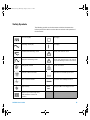
Safety Symbols
The following symbols on the instrument and in the documentation
indicate precautions which must be taken to maintain safe operation of
the instrument.
Direct current (DC)
Off (supply)
Alternating current (AC)
On (supply)
Both direct and alternating current
Caution, risk of electric shock
Three-phase alternating current
Caution, risk of danger (refer to this manual
for specific Warning or Caution information)
Earth (ground) terminal
Caution, hot surface
Protective conductor terminal
Out position of a bi-stable push control
Frame or chassis terminal
In position of a bi-stable push control
Equipotentiality
`
Category II 300 V overvoltage protection
CAT II
300 V
Equipment protected throughout by
double insulation or reinforced
insulation
U2741A User’s Guide
III
User's Guide.book Page IV Friday, August 8, 2008 9:11 AM
General Safety Information
IV
WARN IN G
• Do not use the device if it is damaged. Before you use the device,
inspect the casing. Look for cracks or missing plastic. Do not operate
the device around explosive gas, vapor, or dust.
• Always use the device with the cables provided.
• Observe all markings on the device before establishing any
connection.
• Turn off the device and application system power before connecting
to the I/O terminals.
• When servicing the device, use only the specified replacement parts.
• Do not operate the device with the cover removed or loosened.
• Use only the power adapter provided by the manufacturer to avoid
any unexpected hazards.
CAU T ION
• If the device is used in a manner not specified by the manufacturer, the
device protection may be impaired.
• Always use dry cloth to clean the device. Do not use ethyl alcohol or
any other volatile liquid to clean the device.
• Do not permit any blockage of the ventilation holes of the device.
U2741A User’s Guide
User's Guide.book Page V Friday, August 8, 2008 9:11 AM
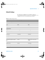
Environmental Conditions
This instrument is designed for indoor use and in an area with low
condensation. The table below shows the general environmental
requirements for this instrument.
CAU T ION
Requirements
Operating temperature
0 °C to 55 °C
Operating humidity
20% to 85% RH non-condensing
Storage temperature
–20 °C to 70 °C
Storage humidity
5% to 90% RH non-condensing
The U2741A USB modular digital multimeter complies with the following
safety and EMC requirements.
•
•
•
•
•
•
U2741A User’s Guide
Environmental conditions
IEC 61010-1:2001/EN61010-1:2001 (2nd Edition)
Canada: CAN/CSA-C22.2 No. 61010-1-04
USA: ANSI/UL 61010-1:2004
IEC 61326-2002/EN 61326:1997+A1:1998+A2:2001+A3:2003
Canada: ICES-001:2004
Australia/New Zealand: AS/NZS CISPR11:2004
V
User's Guide.book Page VI Friday, August 8, 2008 9:11 AM
Regulatory Markings
The CE mark is a registered trademark
of the European Community. This CE
mark shows that the product complies
with all the relevant European Legal
Directives.
The C-tick mark is a registered
trademark of the Spectrum
Management Agency of Australia.
This signifies compliance with
the Australia EMC Framework
regulations under the terms of the
Radio Communication Act of 1992.
ICES/NMB-001 indicates that this
ISM device complies with the
Canadian ICES-001.
Cet appareil ISM est confomre a la
norme NMB-001 du Canada.
This instrument complies with the
WEEE Directive (2002/96/EC)
marking requirement. This affixed
product label indicates that you must
not discard this electrical/electronic
product in domestic household waste.
The CSA mark is a registered
trademark of the Canadian Standards
Association.
VI
U2741A User’s Guide
User's Guide.book Page VII Friday, August 8, 2008 9:11 AM
Waste Electrical and Electronic Equipment (WEEE) Directive
2002/96/EC
This instrument complies with the WEEE Directive (2002/96/EC) marking
requirement. This affixed product label indicates that you must not discard
this electrical/electronic product in domestic household waste.
Product Category:
With reference to the equipment types in the WEEE directive Annex 1, this
instrument is classified as a “Monitoring and Control Instrument” product.
The affixed product label is as shown below.
Do not dispose in domestic household waste
To return this unwanted instrument, contact your nearest Agilent
Technologies, or visit:
www.agilent.com/environment/product
for more information.
U2741A User’s Guide
VII
User's Guide.book Page VIII Friday, August 8, 2008 9:11 AM
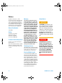
In This Guide…
1
Getting Started
This chapter provides an overview of the U2741A USB modular digital
multimeter, the product outlook, product dimension, and product layout.
This chapter contains instructions on how to install and configure to get
started with the U2741A.
2
Operation and Features
In this chapter, you will get to learn more about the operations and
features that are offered by the U2741A.
3
Measurement Tutorial
In this chapter, you will learn what are the common sources of error in
measurements and how to minimize or eliminate these errors.
4
Characteristics and Specifications
This chapter covers the characteristics and specifications of the U2741A.
VIII
U2741A User’s Guide
User's Guide.book Page IX Friday, August 8, 2008 9:11 AM
DECLARATION OF CONFORMITY
According to EN ISO/IEC 17050-1:2004
Generic example
Manufacturer’s Name:
Manufacturer’s Address:
Agilent Technologies Microwave Products (M) Sdn. Bhd
Bayan Lepas Free Industrial Zone,
11900, Bayan Lepas, Penang, Malaysia
Declares under sole responsibility that the product as originally delivered
Product Name:
Models Number:
Product Options:
Agilent USB Modular Digital Multimeter
U2741A
This declaration covers all options of the above product(s)
complies with the essential requirements of the following applicable European Directives, and
carries the CE marking accordingly:
Low Voltage Directive (2006/95/EC)
EMC Directive (2004/108/EC)
and conforms with the following product standards:
EMC
Standard
Limit
IEC 61326:2002 / EN 61326:1997+A1:1998+A2:2001+A3:2003
CISPR 11:1990 / EN55011:1990
IEC 61000-4-2:1995 / EN 61000-4-2:1995
IEC 61000-4-3:1995 / EN 61000-4-3:1996
IEC 61000-4-4:1995 / EN 61000-4-4:1995
IEC 61000-4-5:1995 / EN 61000-4-5:1995
IEC 61000-4-6:1996 / EN 61000-4-6:1996
IEC 61000-4-11:1994 / EN 61000-4-11:1994
Class A Group 1
4 kV CD, 8 kV AD
3 V/m, 80-1000 MHz
0.5 kV signal lines, 1 kV power lines
0.5 kV line-line, 1 kV line-ground
3 V, 0.15-80 MHz
1 cycle / 100%
Canada: ICES-001:2004
Australia/New Zealand: AS/NZS CISPR11:2004
The product was tested in a typical configuration with Agilent Technologies test systems.
Safety
IEC 61010-1:2001 / EN 61010-1:2001
Canada: CAN/CSA-C22.2 No. 61010-1-04
USA: ANSI/UL 61010-1:2004
206349
This DoC applies to above-listed products placed on the EU market after:
11-July-2008
Tay Eng Su
Date
Quality Manager
For further information, please contact your local Agilent Technologies sales office, agent or distributor,
or Agilent Technologies Deutschland GmbH, Herrenberger Straße 130, 71034 Böblingen, Germany.
Template: A5971-5302-2, Rev. E
U2741A User’s Guide
U2741A
DoC Revision 1.0
IX
User's Guide.book Page X Friday, August 8, 2008 9:11 AM
Product Regulations
EMC
Performance Criteria
IEC 61326-1:2002 / EN 61326-1:1997+A1:1998+A2:2001+A3:2003
CISPR 11:1990 / EN 55011:1990 – Group 1 Class A
IEC 61000-4-2:1995 / EN 61000-4-2:1995 (ESD 4kV CD, 8kV AD)
IEC 61000-4-3:1995 / EN 61000-4-3:1996 (3V/m, 80% AM)
IEC 61000-4-4:1995 / EN 61000-4-4:1995 (EFT 0.5kV line-line, 1kV line-earth)
IEC 61000-4-5:1995 / EN 61000-4-5:1995 (Surge 0.5kV line-line, 1kV line-earth)
IEC 61000-4-6:1996 / EN 61000-4-6:1996 (3V, 0.15~80 MHz, 80% AM, power line)
IEC 61000-4-11:1994 / EN 61000-4-11:1994 (Dips 1 cycle, 100%)
A
A
B
A
A
A
Canada: ICES-001:2004
Australia/New Zealand: AS/NZS CISPR11:2004
Safety
IEC 61010-1:2001 / EN 61010-1:2001
Canada: CAN/CSA-C22.2 No. 61010-1-04
USA: ANSI/UL 61010-1:2004
Additional Information:
The product herewith complies with the essential requirements of the Low Voltage Directive 2006/95/EC and the
EMC Directive 2004/108/EC and carries the CE Marking accordingly (European Union).
1
Performance Criteria:
A Pass - Normal operation, no effect.
B Pass - Temporary degradation, self recoverable.
C Pass - Temporary degradation, operator intervention required.
D Fail - Not recoverable, component damage.
N/A – Not applicable
Notes:
Regulatory Information for Canada
ICES/NMB-001:2004
This ISM device complies with Canadian ICES-001.
Cet appareil ISM est confomre à la norme NMB-001 du Canada.
Regulatory Information for Australia/New Zealand
This ISM device complies with Australian/New Zealand AS/NZS CISPR11:2004
X
U2741A User’s Guide
User's Guide.book Page XI Friday, August 8, 2008 9:11 AM
Contents
1
Getting Started
Introduction
1
2
Product at a Glance
Product Outlook
3
3
Product Dimensions 5
Dimensions without Bumpers 5
Dimensions with Bumpers 6
Standard Purchase Items
7
Inspection and Maintenance 8
Initial Inspection 8
Electrical Check 8
General Maintenance 9
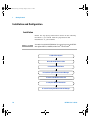
Installation and Configuration 10
Installation 10
A. Check Your System 11
B. Install the IO Libraries Suite 12
C. Install the Module Driver 13
D. Install the Agilent Measurement Manager 14
E. Connect the Module to Your PC 16
F. Verify Your Module Connection 21
G. Launch Your Agilent Measurement Manager 23
Instrument Configuration 25
55-Pin Backplane Connector Pin Configuration
Chassis Installation 26
U2741A User’s Guide
25
XI
User's Guide.book Page XII Friday, August 8, 2008 9:11 AM
Contents
2
Operation and Features
Powering Up
27
28
Making Measurements 29
Measuring DC Voltage 29
Measuring AC Voltage 31
Measuring DC Current 32
Measuring AC Current 33
Measuring Resistance 34
Measuring Frequency 36
Testing Continuity 37
Testing Diodes 38
Measuring Temperature 39
Restoring Instrument State
Autozero 41
Ranging 42
Default Settings
43
Triggering the U2741A
44
System-Related Operation
Error Conditions 46
3
41
Measurement Tutorial
46
47
DC Measurement Considerations
Noise Rejection
48
49
Resistance Measurement Considerations
AC Measurements
52
55
Other Primary Measurement Functions 58
Frequency Measurement Errors 58
DC Current Measurements 58
Other Sources of Measurement Error
XII
60
U2741A User’s Guide
User's Guide.book Page XIII Friday, August 8, 2008 9:11 AM
Contents
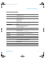
4
Characteristics and Specifications
Product Characteristics
Product Specifications
65
67
Frequency specifications
Temperature specifications
U2741A User’s Guide
63
70
71
XIII
User's Guide.book Page XIV Friday, August 8, 2008 9:11 AM
Contents
XIV
U2741A User’s Guide
User's Guide.book Page XV Friday, August 8, 2008 9:11 AM
List of Figures
Figure 1-1
Figure 3-1
Figure 3-2
Figure 3-3
U2741A User’s Guide
55-pin backplane connector pin configuration
Common mode source error 49
Ground loop induced error 51
Burden voltage in current measurement 59
25
XV
User's Guide.book Page XVI Friday, August 8, 2008 9:11 AM
Contents
XVI
U2741A User’s Guide
User's Guide.book Page XVII Friday, August 8, 2008 9:11 AM
List of Tables
Table 1-1 SSI connector pin description 25
Table 2-1 Default settings summary 43
Table 3-1 Thermoelectric voltage for dissimilar metals
connections 48
Table 3-2 Power dissipation for various resistance ranges 54
Table 3-3 Waveform shapes and their parameters 55
Table 4-1 DC accuracy 67
Table 4-2 AC accuracy for voltage 68
Table 4-3 Temperature coefficient for voltage 69
Table 4-4 AC accuracy for current 69
Table 4-5 Temperature coefficient for current 69
Table 4-6 Frequency accuracy 70
Table 4-7 Frequency sensitivity for AC voltage 70
Table 4-8 Temperature accuracy ± (% of reading + no. of least
significant digit) 71
U2741A User’s Guide
XVII
User's Guide.book Page XVIII Friday, August 8, 2008 9:11 AM
Contents
XVIII
U2741A User’s Guide
User's Guide.book Page 1 Friday, August 8, 2008 9:11 AM
U2741A USB Modular 5.5 Digits Digital Multimeter
User’s Guide
1
Getting Started
Introduction 2
Product at a Glance 3
Product Outlook 3
Product Dimensions 5
Dimensions without Bumpers 5
Dimensions with Bumpers 6
Standard Purchase Items 7
Inspection and Maintenance 8
Initial Inspection 8
Electrical Check 8
General Maintenance 9
Installation and Configuration 10
Installation 10
A. Check Your System 11
B. Install the IO Libraries Suite 12
C. Install the Module Driver 13
D. Install the Agilent Measurement Manager 14
E. Connect the Module to Your PC 16
F. Verify Your Module Connection 21
G. Launch Your Agilent Measurement Manager 23
Instrument Configuration 25
55-Pin Backplane Connector Pin Configuration 25
Chassis Installation 26
Agilent Technologies
1
User's Guide.book Page 2 Friday, August 8, 2008 9:11 AM
1
Getting Started
Introduction
The Agilent U2741A is a 5.5 digits digital multimeter that
can operate as standalone or as a modular unit when used
with the U2781A USB modular instrument chassis.
U2741A can perform the following measurements:
• DC Voltage
• AC Voltage
• DC Current
• AC Current
• Resistance
• Diode Test
• Continuity Test
• Temperature
• Frequency
The U2741A is controlled remotely over a USB interface via
the Agilent Measurement Manager (AMM) software. The
U2741A can also be programmed using the provided drivers
or via SCPI commands in your customized application.
2
U2741A User’s Guide
User's Guide.book Page 3 Friday, August 8, 2008 9:11 AM
Getting Started
1
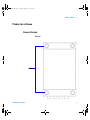
Product at a Glance
Product Outlook
Top view
Bumpers
U2741A User’s Guide
3
User's Guide.book Page 4 Friday, August 8, 2008 9:11 AM
1
Getting Started
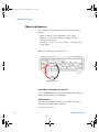
Front view
4-wire Ω Lo Sense
4-wire Ω Hi Sense
VOLT LO
VOLT HI
USB Indicator
Power Indicator
Fuse holder
Rear view
55-pin backplane connector
USB inlet
Power inlet
Fastening hole for USB cable with locking mechanism
4
U2741A User’s Guide
User's Guide.book Page 5 Friday, August 8, 2008 9:11 AM
Getting Started
1
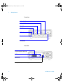
Product Dimensions
Dimensions without Bumpers
Top view
105.00 mm
175.00 mm
11.50 mm
Front view
25.00 mm
U2741A User’s Guide
5
User's Guide.book Page 6 Friday, August 8, 2008 9:11 AM
1
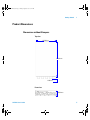
Getting Started
Dimensions with Bumpers
Top view
117.00 mm
180.00 mm
8.60 mm
Front view
41.00 mm
6
U2741A User’s Guide
User's Guide.book Page 7 Friday, August 8, 2008 9:11 AM
Getting Started
1
Standard Purchase Items
Verify that you have received the following items with your
unit. If anything is missing or damaged, please contact the
nearest Agilent Sales Office.
✔ 12 V, 2 A AC/DC adapter
✔ Power cord
✔ Standard Test Lead
✔ USB Standard- A to Mini- B interface cable
✔ L- Mount kit (used with the modular instrument chassis)
✔ Agilent Automation- Ready CD (contains the Agilent IO
Libraries Suite)
✔ Agilent USB Modular Products Quick Start Guide
✔ Agilent USB Modular Products Reference CD- ROM
✔ Agilent Measurement Manager Quick Reference Card
✔ Certificate of Calibration
U2741A User’s Guide
7
User's Guide.book Page 8 Friday, August 8, 2008 9:11 AM
1
Getting Started
Inspection and Maintenance
Initial Inspection
When you receive your U2741A, inspect the unit for any
obvious damage such as broken terminals or cracks, dents,
and scratches on the casing that may occur during shipment.
If any damage is found, notify the nearest Agilent Sales
Office immediately. The front of this manual contains the
warranty information.
Keep the original packaging in case the U2741A has to be
returned to Agilent in the future. If you return the U2741A
for service, attach a tag identifying the owner and model
number. Also include a brief description of the problem.
Electrical Check
For verification procedures, refer to Agilent U2741A USB
Modular 5.5 Digits Digital Multimeter Service Guide. The
procedures will verify to a high level of confidence that the
U2741A is operating in accordance to its specifications.
8
U2741A User’s Guide
User's Guide.book Page 9 Friday, August 8, 2008 9:11 AM
Getting Started
1
General Maintenance
General maintenance
N O TE
Any repair that is not covered in your modular product manuals should
only be performed by qualified personnel.
1 Power off your module and remove the power cord and
I/O cable from your device.
2 Remove your module from the bumper casing.
3 Shake out any dirt that may have accumulated on the
module.
4 Wipe your module with a dry cloth and install the
bumper back in place.
U2741A User’s Guide
9
User's Guide.book Page 10 Friday, August 8, 2008 9:11 AM
1
Getting Started
Installation and Configuration
Installation
Follow the step-by-step instructions shown in the following
flowchart to get started with the preparations and
installations of your U2741A.
N O TE
You need to install the IVI-COM driver if you are going to use the U2741A
with Agilent VEE Pro, LabVIEW, or Microsoft® Visual Studio®.
A. Check Your System
B. Install the IO Libraries Suite
C. Install the Module Driver
D. Install the Agilent Measurement Manager
E. Connect the Module to Your PC
F. Verify Your Module Connection
G. Launch Your Agilent Measurement Manager
10
U2741A User’s Guide
User's Guide.book Page 11 Friday, August 8, 2008 9:11 AM
Getting Started
1
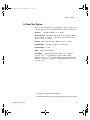
A. Check Your System
Prior to any installation or configuration, please ensure that
your PC meets the following minimum system requirements.
Processor
1.6 GHz Pentium® IV or higher
Operating system Windows® XP Professional or Home Edition
(Service Pack 1 or later), or Windows® 2000 Professional
(Service Pack 4 or later)
Browser
Microsoft® Internet Explorer 5.01 or higher
Available RAM
Hard-disk space
Video
512 MB or higher recommended
1 GB
Super VGA 800×600
Prerequisites Agilent IO Libraries Suite 14.2 or higher
(version 15.0 [1] recommended), Agilent T&M Toolkit
Runtime version 2.1 [2], Agilent T&M Toolkit Redistributable
Package 2.1 patch [2], Microsoft® .NET Framework version
1.1 and 2.0 [2]
[1] Available on Agilent Automation-Ready CD.
[2] Bundled with Agilent Measurement Manager application software installer.
U2741A User’s Guide
11
User's Guide.book Page 12 Friday, August 8, 2008 9:11 AM
1
Getting Started
B. Install the IO Libraries Suite
The IO Libraries Suite 14.2 or higher is available on the
Agilent Automation-Ready CD that comes with the standard
purchase of the U2741A.
N O TE
• If you do not have the Agilent Automation-Ready CD, obtain the IO
Libraries Suite 14.2 or higher at http://www.agilent.com/find/iolib.
• Disconnect any USB instruments or connectivity interface from your
PC.
1 Close all other applications on your PC, insert the Agilent
Automation-Ready CD into your CD-ROM drive, and follow
the instructions on your screen.
2 If the IO Libraries Suite installation does not start
automatically, go to Start > Run (on the Windows Start
menu) and type <drive>:\autorun\auto.exe where
<drive> is your CD-ROM drive location.
3 If you obtain the IO Libraries Suite from the web, save
the self-extracting zip file (*.exe) to any location on your
hard disk.
4 Double-click the installation file to launch the installation.
5 Follow the instructions on your screen to proceed with
the installation.
6 After the installation has completed, you will see the IO
Control icon on the Windows taskbar notification area as
shown below.
12
U2741A User’s Guide
User's Guide.book Page 13 Friday, August 8, 2008 9:11 AM
Getting Started
N O TE
1
For detailed installation instructions, refer to the Agilent IO Libraries Suite
Getting Started Guide at http://www.agilent.com/find/iolib.
C. Install the Module Driver
N O TE
Please ensure that there are no instruments connected to the PC when
installing the driver.
1 Verify that your PC meets the minimum system
requirements as stated in “A. Check Your System” on
page 11.
2 Insert the Product Reference CD-ROM into your CD-ROM
drive.
3 The installer will automatically launch the Agilent Modular
Products Installation Menu. Click Hardware Driver to begin the
installation.
U2741A User’s Guide
13
User's Guide.book Page 14 Friday, August 8, 2008 9:11 AM
1
Getting Started
4 If the menu does not launch automatically, go to Start >
Run (on the Windows Start menu) and type <drive>:\
Driver\Hardware\setup_Hw.exe where <drive> is
your CD-ROM drive location. Click OK to begin the
installation.
5 Follow the instructions on the screen and click Next to
proceed.
6 Click Install to begin the installation. Follow the
instructions on the screen to proceed with the
installation.
7 Click Finish when the installation has completed.
D. Install the Agilent Measurement Manager
1 If you have done “C. Install the Module Driver” on
page 13, proceed to Step 2. If not, close all other
applications on your PC and insert the Product Reference
CD-ROM into your CD-ROM drive.
2 Click Measurement Manager on the U2741A Installation Menu to
begin the installation.
14
U2741A User’s Guide
User's Guide.book Page 15 Friday, August 8, 2008 9:11 AM
Getting Started
1
3 If the installation menu does not appear after a few
seconds, go to Start > Run and type <drive>:\
Application\Modular Instruments Measurement
Manager\setup.exe where <drive> is your CD-ROM
drive location.
4 Click OK to begin the installation.
5 If you do not have any of the prerequisites installed, the
InstallShield Wizard software prerequisite will appear.
6 Click OK to begin the installation of the listed missing
prerequisites.
7 Once the above installation has completed, installation of
the Measurement Manager software will proceed as
normal.
8 The Measurement Manager InstallShield Wizard dialog will
appear. Click Next to begin.
9 Read the License Agreement and select I accept the terms in
the License Agreement to proceed. You may click Print to
print a hardcopy of the Agilent License Terms for
reference. Click Next to proceed.
10 Fill in the Customer Information Form accordingly and
click Next.
11 Click Next to install to the specified folder or click Change
to install to a different folder.
12 Click Install to begin the installation of the Measurement
Manager.
13 Click Finish when the installation has completed.
14 A shortcut to this software will be created on your
desktop.
N O TE
using
U2741A User’s Guide
USING THE LICENSED MATERIALS INDICATES YOUR ACCEPTANCE OF
THE LICENSE TERMS. IF YOU DO NOT AGREE TO ALL OF THESE TERMS,
YOU MAY RETURN ANY UNOPENED LICENSED MATERIAL FOR A FULL
REFUND. IF THE LICENSED MATERIALS ARE BUNDLED OR PRELOADED
WITH ANOTHER PRODUCT, YOU MAY RETURN THE ENTIRE UNUSED
PRODUCT FOR A FULL REFUND.
15
User's Guide.book Page 16 Friday, August 8, 2008 9:11 AM
1
Getting Started
E. Connect the Module to Your PC
N O TE
Ensure that the AMM is installed before proceeding.
1 After the installations have completed, connect the power
cord to the AC/DC power adapter. The AC/DC power
adapter requirements are 100 to 240 VAC, 50/60 Hz, with
an output voltage of +12 VDC.
2 Insert the DC output plug from the AC/DC power adapter
to the power jack on the rear panel of the U2741A.
3 Connect the U2741A to any USB port on your PC with the
bundled USB cable.
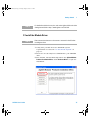
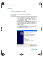
4 Your PC will automatically detect the connected unit and
the Found New Hardware Wizard window will appear. Select
Yes, this time only and click Next to proceed.
16
U2741A User’s Guide
User's Guide.book Page 17 Friday, August 8, 2008 9:11 AM
Getting Started
1
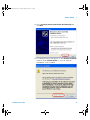
5 Select Install the software automatically (Recommended) and
click Next.
6 A warning message will appear on the Hardware Installation
window. Click Continue Anyway to proceed with the
installation of the U2741A.
U2741A User’s Guide
17
User's Guide.book Page 18 Friday, August 8, 2008 9:11 AM
1
Getting Started
N O TE
If you do not wish to receive similar warning messages in the future,
follow the instructions below.
• Go to Start > Control Panel and double-click System.
• Select the Hardware tab and click Driver Signing on the Drivers panel.
The Driver Signing Options dialog box will appear.
• Select Ignore to disable the warning message.
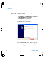
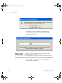
7 Click Finish to complete the installation.
8 The Assign USB device alias window will appear. Each time
the U2741A is plugged in, this dialog box will appear. To
disable this dialog, select the Never show this dialog option
in the Show this dialog panel and click OK.
18
U2741A User’s Guide
User's Guide.book Page 19 Friday, August 8, 2008 9:11 AM
Getting Started
1
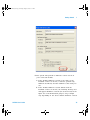
9 The system will perform a firmware version check on
your connected module.
a If the module firmware version is the same as the
installed version on the PC, it will not perform any
firmware download, and the U2741A is then ready for
use.
b If the module firmware version differs from the
installed version on the PC, the following message box
will appear. Firmware versions (V1.00 and V1.01) in the
figure are for demonstration purpose only, it might
vary depending on the device and PC firmware version.
U2741A User’s Guide
19
User's Guide.book Page 20 Friday, August 8, 2008 9:11 AM
1
Getting Started
c Click Yes to begin the firmware download. The
following message box will appear indicating the
download in progress.
N O TE
i Ensure that you do not remove the USB and power connection until the
firmware download has completed.
ii It is recommended to power cycle the U2741A after every firmware upgrade.
d Your U2741A is ready for use once the firmware
upgrade has completed.
20
U2741A User’s Guide
User's Guide.book Page 21 Friday, August 8, 2008 9:11 AM
Getting Started
1
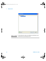
F. Verify Your Module Connection
The Agilent Connection Expert is one of the utilities in the
IO Libraries. The Connection Expert configures the
connected instruments and enables communication. It is able
to automatically detect the U2741A devices plugged into the
PC.
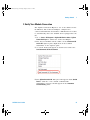
1 Go to Start > All Programs > Agilent IO Libraries Suite > Agilent
Connection Expert to launch the Connection Expert.
2 The detected U2741A will be visible on the Instrument I/O
on this PC explorer pane. Right-click on the U2741A
instrument on the explorer pane.
3 A context menu will appear as shown below and select
Send Commands To This Instrument.
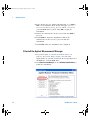
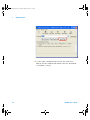
4 The Agilent Interactive IO dialog box will appear. Click Send &
Read to send the *IDN? default command. The
instrument’s response should appear in the Instrument
Session History panel.
U2741A User’s Guide
21
User's Guide.book Page 22 Friday, August 8, 2008 9:11 AM
1
Getting Started
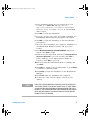
5 A successful communication between the Connection
Expert and the U2741A will indicate that the instrument
is installed correctly.
22
U2741A User’s Guide
User's Guide.book Page 23 Friday, August 8, 2008 9:11 AM
Getting Started
1
G. Launch Your Agilent Measurement Manager
N O TE
• The IO Control will launch automatically when you start your PC.
• Launching the Measurement Manager without the IO Control running
will cause the Measurement Manager to fail to detect or establish any
connection with the U2741A connected to your PC.
• To run the IO Control, go to Start > All Programs > Agilent IO
Libraries Suite > Utilities > IO Control.
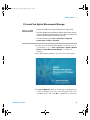
1 Double-click the Measurement Manager software icon on
your desktop or go to Start > All Programs > Agilent > Modular
Products > Agilent Measurement Manager to launch the
software.
2 The Measurement Manager welcome screen will appear.
3 The Select USB Device dialog box will appear displaying the
connected U2741A devices. To start the application, select
a U2741A device and click OK to establish the connection.
U2741A User’s Guide
23
User's Guide.book Page 24 Friday, August 8, 2008 9:11 AM
1
Getting Started
N O TE
24
For more information on how to use the Measurement Manager, refer to
the Agilent Measurement Manager help file.
U2741A User’s Guide
User's Guide.book Page 25 Friday, August 8, 2008 9:11 AM
Getting Started
1
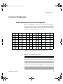
Instrument Configuration
55-Pin Backplane Connector Pin Configuration
The 55- pin backplane connector is used when the U2741A
module is inserted into the U2781A USB modular instrument
chassis. For more details, refer to the Agilent U2781A USB
Modular Instrument Chassis User's Guide.
GND
GND
GND
GND
GND
GND
GND
GND
GND
GND
NC
NC
NC
NC
NC
NC
NC
NC
VBUS
GND
USB_D–
E
GND
TRIG3
GND
TRIG2
GND
TRIG1
GND
TRIG0
GND
GND
USB_D+
D
TRIG4
GND
TRIG5
GND
TRIG6
GND
TRIG7
GND
+12 V
+12 V
GND
C
GA2
GA1
GA0
NC
+12 V
+12 V
+12 V
B
A
nBPUB CLK10M
GND STAR_TRIG
GND
NC
NC
NC
NC
NC
NC
NC
NC
+12 V
+12 V
+12 V
11
10
9
8
7
6
5
4
3
2
1
Figure 1-1
F
55-pin backplane connector pin configuration
Table 1-1 SSI connector pin description
U2741A User’s Guide
SSI timing signal
Functionality
GND
Ground
NC
Not connected
VBUS
USB bus power sensing input
USB_D+, USB_D–
USB differential pair
TRIG0~TRIG7
Trigger bus
+12 V
+12 V power with 4 A current
nBPUB
USB backplane input detect
25
User's Guide.book Page 26 Friday, August 8, 2008 9:11 AM
1
Getting Started
Table 1-1 SSI connector pin description
SSI timing signal
Functionality
CLK10M
10 MHz clock source
STAR_TRIG
Star trigger
GA0,GA1,GA2
Geographical address pin
Chassis Installation
The L- Mount kit is to be installed to your U2741A module.
The following instructions describe the simple procedure of
installing the L- Mount kit and your module in the chassis.
1 Unpack the L- Mount kit from the packaging.
2 Remove your U2741A module from the bumper casing.
3 Use a Phillips screwdriver to fasten the L- Mount kit to
your U2741A module.
4 Insert your U2741A module into the U2781A chassis with
the 55- pin backplane connector positioned at the bottom
of the module.
5 Once you have slotted in the module, tighten the screws
of the L- Mount kit to secure the connection.
26
U2741A User’s Guide
User's Guide.book Page 27 Friday, August 8, 2008 9:11 AM
U2741A USB Modular 5.5 Digits Digital Multimeter
User’s Guide
2
Operation and Features
Powering Up 28
Making Measurements 29
Measuring DC Voltage 29
Measuring AC Voltage 31
Measuring DC Current 32
Measuring AC Current 33
Measuring Resistance 34
Measuring Frequency 36
Testing Continuity 37
Testing Diodes 38
Measuring Temperature 39
Restoring Instrument State 41
Autozero 41
Ranging 42
Default Settings 43
Triggering the U2741A 44
System-Related Operation 46
Error Conditions 46
This chapter contains the details on how to configure your
U2741A USB modular digital multimeter to perform the
various measurement functions either through the software
front panel or by sending SCPI commands remotely via the
USB interface.
Agilent Technologies
27
User's Guide.book Page 28 Friday, August 8, 2008 9:11 AM
2
Operation and Features
Powering Up
Take note of the following when you power up the U2741A.
• The U2741A can only be operated via the USB interface.
• Before you can control the U2741A, you need to install
the hardware driver and the IO Libraries Suite 14.2 or
higher. Both of these are included when you purchase the
U2741A. Refer to Chapter 1, “B. Install the IO Libraries
Suite” on page 12 and “C. Install the Module Driver” on
page 13 for the installation procedure.
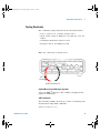
• On the front panel of the U2741A, there are two LED
indicators. Refer to Chapter 1, “Product Outlook” on
page 3.
• Power indicator lights up once the U2741A is powered up.
It will blink if there is a system error.
• USB indicator will only blink when there is data exchange
activity between the U2741A and the PC.
You can control your U2741A via the AMM for U2741A or
via SCPI commands sent through the USB interface from
your own application programs.
The Agilent U2741A complies with the syntax rules and
conventions of SCPI commands.
You can determine the U2741A's SCPI language version by
sending the SYSTem:VERSion? command from the remote
interface.
For a complete discussion of U2741A's SCPI syntax, refer to
the Agilent U2741A Programmer's Reference.
28
U2741A User’s Guide
User's Guide.book Page 29 Friday, August 8, 2008 9:11 AM
Operation and Features
2
Making Measurements
The following pages show how to make measurement
connections and how to select measurement functions from
the front panel for each of the measurement functions.
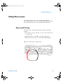
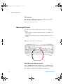
Measuring DC Voltage
The DC voltage measurement function has the following
features:
• Five ranges to select: 100 mV, 1 V, 10 V, 100 V, and 300 V
or, auto- range.
• Input impedance is 10 MΩ for all ranges (typical).
• Input protection is 300 V on all ranges (HI terminal).
Make the connection as shown below.
+
–
DC Voltage Source
U2741A User’s Guide
29
User's Guide.book Page 30 Friday, August 8, 2008 9:11 AM
2
Operation and Features
Agilent Measurement Manager operation
Select the DCV function and desired range. A suitable range
should be selected to give the best measurement resolution.
The reading is displayed and updated continuously.
SCPI commands
The following example shows how to make a DC voltage
measurement using SCPI commands.
MEASure[:VOLTage]:DC?
30
U2741A User’s Guide
User's Guide.book Page 31 Friday, August 8, 2008 9:11 AM
Operation and Features
2
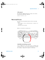
Measuring AC Voltage
The AC voltage measurement function has the following
features:
• Five ranges to select: 100 mVrms, 1 Vrms, 10 Vrms, 100
Vrms, and 250 Vrms or, auto- range.
• Measures the AC -coupled true rms.
• Measures within the stipulated accuracy at a crest factor
of a maximum of 5:1 (full scale).
• Input impedance is 1 MΩ ± 2% in parallel with less than
120 pF capacitance on all ranges.
Make the connection as shown below.
+
–
AC Voltage Source
Agilent Measurement Manager operation
Select the ACV function and desired range. A suitable range
should be selected to give the best measurement resolution.
The reading is displayed and updated continuously.
U2741A User’s Guide
31
User's Guide.book Page 32 Friday, August 8, 2008 9:11 AM
2
Operation and Features
SCPI commands
The following example shows how to make an AC voltage
measurement using SCPI commands.
MEASure[:VOLTage]:AC?
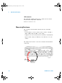
Measuring DC Current
The DC current measurement function has the following
features:
• Three ranges to select: 10 mA, 100 mA, 1 A and 2 A or,
auto- range.
• Input protection fuse is 2 A, voltage rating 250 V on all
ranges.
Make the connection as shown below.
–
+
DC Current Source
Agilent Measurement Manager operation
Select the DCI function and desired range. A suitable range
should be selected to give the best measurement resolution.
The reading is displayed and updated continuously.
32
U2741A User’s Guide
User's Guide.book Page 33 Friday, August 8, 2008 9:11 AM
Operation and Features
2
SCPI commands
The following example shows how to make a DC current
measurement using SCPI commands.
MEASure:CURRent[:DC]?
Measuring AC Current
The AC current measurement function has the following
features:
• Three ranges to select: 10 mA, 100 mA, 1 A and 2 A or,
auto- range.
• Measures true rms value.
Make the connection as shown below.
–
+
AC Current Source
Agilent Measurement Manager operation
Select the ACI function and desired range. A suitable range
should be selected to give the best measurement resolution.
The reading is displayed and updated continuously.
U2741A User’s Guide
33
User's Guide.book Page 34 Friday, August 8, 2008 9:11 AM
2
Operation and Features
SCPI commands
The following example shows how to make an AC current
measurement using SCPI commands.
MEASure:CURRent:AC?
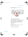
Measuring Resistance
The resistance measurement function has the following
features:
• Seven ranges to select: 100 Ω, 1 kΩ , 10 kΩ , 100 kΩ, 1
MΩ, 10 MΩ, and 100 MΩ or, auto- range.
• Supports two- wire and four- wire resistance measurement.
• Open circuit voltage is limited to less than 4.5 V on all
ranges.
The figure below shows a two- wire resistance measurement
connection.
Test
Current
Resistance
34
U2741A User’s Guide
User's Guide.book Page 35 Friday, August 8, 2008 9:11 AM
Operation and Features
2
The following figure shows a four- wire resistance
measurement connection.
Test Current
Agilent Measurement Manager operation
Select the 2-Wired Ω function and desired range for two- wire
resistance measurement. Select the 4-Wired Ω function and
desired range for four- wire resistance measurement. A
suitable range should be selected to give the best
measurement resolution. The reading is displayed and
updated continuously.
SCPI commands
The following example shows how to make a resistance
measurement using SCPI commands.
Two- wire : MEASure:RESistance?
Four- wire : MEASure:FRESistance?
U2741A User’s Guide
35
User's Guide.book Page 36 Friday, August 8, 2008 9:11 AM
2
Operation and Features
Measuring Frequency
The frequency measurement function has the following
features:
• Range is based on the amplitude of the signal.
• Employs a reciprocal counting technique as the
measurement method.
• Gate time can be set at 0.1 second or 1 second of the
input signal.
Make the connection as shown below.
~
Frequency Source
Agilent Measurement Manager operation
Select the Freq function and desired range. The reading is
displayed and updated continuously.
SCPI commands
The following example shows how to make a frequency
measurement using SCPI commands.
MEASure:FREQuency?
36
U2741A User’s Guide
User's Guide.book Page 37 Friday, August 8, 2008 9:11 AM
Operation and Features
2
Testing Continuity
The continuity testing function has the following features:
• Uses a 1 mA ± 0.2% constant current source.
• Open circuit voltage is limited to less than 4.5 V for all
ranges.
• Continuity threshold is fixed at 10 Ω.
• Response time is 60 samples/second.
Make the connection as shown below.
Test
Current
Open or closed circuit
Agilent Measurement Manager operation
Select the Cont-))) function. The reading is displayed and
updated continuously.
SCPI commands
The following example shows how to make a Continuity Test
measurement using SCPI commands.
MEASure:CONTinuity?
U2741A User’s Guide
37
User's Guide.book Page 38 Friday, August 8, 2008 9:11 AM
2
Operation and Features
Testing Diodes
The diode testing function has the following features:
• Uses a 1 mA ± 0.2% constant current source.
• Open circuit voltage is limited to less than 4.5 V for all
ranges.
• Response time is 60 samples/second.
Make the connection as shown below.
Forward bias
Agilent Measurement Manager operation
Select the Diode
function. The reading is displayed and
updated continuously.
SCPI commands
The following example shows how to make a Diode Test
measurement using SCPI commands.
MEASure:DIODe?
38
U2741A User’s Guide
User's Guide.book Page 39 Friday, August 8, 2008 9:11 AM
Operation and Features
2
Measuring Temperature
The temperature measurement function has the following
features:
• The measurement range is dependant on the type of
temperature sensor used. For the specification details of
the temperature sensors, please refer to Table 4- 8 on
page 71.
• Measurements are in auto- range for 5 kΩ thermistor
probe.
• Supports the thermistor.
Make the connection as shown below.
Thermistor
Agilent Measurement Manager operation
Select the Temp function and the type of thermistor used.
The reading is displayed and updated continuously.
U2741A User’s Guide
39
User's Guide.book Page 40 Friday, August 8, 2008 9:11 AM
2
Operation and Features
SCPI commands
The following example shows how to make a temperature
measurement using SCPI commands.
MEASure:TEMPerature? THER
40
//Used for thermistor
measurement
U2741A User’s Guide
User's Guide.book Page 41 Friday, August 8, 2008 9:11 AM
Operation and Features
2
Restoring Instrument State
The U2741A automatically saves the last configuration
whenever a power- down event occurs and restores to the
last power- down state when you turn on the instrument.
Autozero
When autozero is enabled, the digital multimeter internally
disconnects the input signal following each measurement,
and takes a zero reading. It then subtracts the zero reading
from the preceding reading. This prevents offset voltages
present on the digital multimeter’s input circuitry from
affecting measurement accuracy.
This is applicable to dc voltage, dc current, two- wire ohms
and temperature measurements only.
SCPI Commands
The following commands are used to set the autozero:
VOLTage:ZERO:AUTO {OFF|ON}
CURRent:ZERO:AUTO {OFF|ON}
RESistance:ZERO:AUTO {OFF|ON}
TEMPerature:ZERO:AUTO {OFF|ON}
U2741A User’s Guide
41
User's Guide.book Page 42 Friday, August 8, 2008 9:11 AM
2
Operation and Features
Ranging
You can let the digital multimeter automatically select the
range using auto range or you can select a fixed range using
manual range. Autoranging is convenient because the digital
multimeter automatically selects the appropriate range for
each measurement. However, you can use manual range for
faster measurements since the digital multimeter does not
have to determine which range to use for each measurement.
• Autorange thresholds:
Down range at:
<10% of range
Up range at:
>120% of range
• For manual range, if the input signal is greater than the
present range can measure, the digital multimeter gives an
overload indication: “9.9E+37” from the remote interface.
For auto range, the digital multimeter will give an
overload indication "9.9E+37" if the input signal is greater
than the highest measurement range.
• The range is fixed for continuity tests (1 kΩ range) and
diode tests (1 VDC range with 1 mA current source
output).
SCPI Commands
You can set the range using any of the following commands.
CONFigure:<function> {<range>|MIN|MAX|AUTO},
{<resolution>|MIN|MAX|DEF}
MEASure:<function>? {<range>|MIN|MAX|AUTO},
{<resolution>|MIN|MAX|DEF}
<function>:RANGe {<range>|MINimum|MAXimum|AUTO}
<function>:RANGe:AUTO {OFF|ON}
42
U2741A User’s Guide
User's Guide.book Page 43 Friday, August 8, 2008 9:11 AM
Operation and Features
2
Default Settings
The table below summarizes the U2741A's settings as
received from the factory, at power- on or following the *RST
command received over the USB remote interface.
Table 2-1 Default settings summary
Parameter
Factory Setting
Power-on/Reset State
Function
DCV
DCV
Range
AUTO
AUTO
Resolution
5.5 digits
5.5 digits
Temperature Unit
°C
User setting
Auto Trigger
Auto Trigger
Power-Down Recall
Disabled
User Setting
Stored States
0-10 Cleared
No Change
Reading Output Buffer
Cleared
Cleared
Error Queue
Cleared
Cleared
Power-on Status Clear
Enabled
User Setting
Status Registers, Masks & Transition
Filter
Cleared
Cleared in power-on status clear
enabled
Calibration State
Secured
User Setting
Calibration Value
0
No Change
Calibration String
Cleared
No Change
Measurement Configuration
Trigger Operation
Trigger Source
System-Related Operation
Calibration
U2741A User’s Guide
43
User's Guide.book Page 44 Friday, August 8, 2008 9:11 AM
2
Operation and Features
Triggering the U2741A
At power- up, the default trigger source is immediate. To
make a measurement, the following steps are to be followed:
• Configure the U2741A by selecting the function, range,
resolution, and so on.
• Specify the digital multimeter's trigger source. You can
select software bus trigger or an immediate internal
trigger (default trigger source).
• Ensure that the U2741A is in wait- for- trigger state to
accept a trigger from the specified source.
Immediate triggering
In the immediate trigger mode, the trigger signal is always
present. When you place the U2741A in the wait- for- trigger
state, the trigger is issued immediately. This is the default
trigger source.
SCPI command
The following command sets the trigger source to immediate:
TRIGger:SOURce IMMediate
Software bus triggering
The bus trigger mode is initiated by sending a bus trigger
command, after selecting BUS as the trigger source.
SCPI command
The following command sets the trigger source to bus:
TRIGger:SOURce BUS
The MEASure? and READ? command overwrites the BUS
trigger and triggers the digital multimeter and returns a
measurement.
44
U2741A User’s Guide
User's Guide.book Page 45 Friday, August 8, 2008 9:11 AM
Operation and Features
2
The INITiate command changes the state of the triggering
to wait- for- trigger state. Measurements will begin when the
specified trigger conditions are satisfied.
Star Triggering
The star trigger can only be applied when the U2741A is
connected into the U2781A modular instrument chassis. It is
used to trigger multiple modular units in the chassis.
SCPI command
TRIGger:SOURce STRG
Synchronization Status
This is to configure the synchronization of multiple units of
U2741A (slave only) when used in the U2781A modular
instrument chassis. Only one master can be assigned at a
time.
SCPI command
CONFigure:SSI {NONE|SLAVe}
Refer to the Agilent U2741A Programmer's Reference for
complete description and syntax for these commands.
U2741A User’s Guide
45
User's Guide.book Page 46 Friday, August 8, 2008 9:11 AM
2
Operation and Features
System-Related Operation
This section provides information on system- related topics
such as performing a self- calibration routine and reading
error conditions.
Error Conditions
A record of up to 20 errors can be stored in the U2741A's
error queue. Refer to the programming guide for more
information on the error messages.
Agilent Measurement Manager Operation
A message box will appear once an error occurs while
operating the U2741A using the AMM.
46
U2741A User’s Guide
User's Guide.book Page 47 Friday, August 8, 2008 9:11 AM
U2741A USB Modular 5.5 Digits Digital Multimeter
User’s Guide
3
Measurement Tutorial
DC Measurement Considerations 48
Noise Rejection 49
Resistance Measurement Considerations 52
AC Measurements 55
Other Primary Measurement Functions 58
Frequency Measurement Errors 58
DC Current Measurements 58
Other Sources of Measurement Error 60
The Agilent U2741A is capable of making accurate
measurements but in order to achieve the best accuracy, you
must take the necessary steps to eliminate potential
measurement errors. This chapter describes common errors
found in measurements and gives suggestions to help you
avoid or minimize these errors.
Agilent Technologies
47
User's Guide.book Page 48 Friday, August 8, 2008 9:11 AM
3
Measurement Tutorial
DC Measurement Considerations
Thermal EMF errors
Thermoelectric voltages are the most common source of
error in low- level DC voltage measurements. Thermoelectric
voltages are generated when you make circuit connections
using dissimilar metals at different temperatures.
Each metal- to- metal junction forms a thermocouple, which
generates a voltage proportional to the junction temperature.
You should take the necessary precautions to minimize
thermocouple voltages and temperature variations in
low- level voltage measurements. The best connections are
formed using copper- to- copper crimped connections, as the
digital multimeter's input terminals are copper alloy. The
table below
shows common thermoelectric voltages for connections
between dissimilar metals.
Table 3-1 Thermoelectric voltage for dissimilar metals connections
48
Copper to -
Approx. mV / °C
Copper to -
Approx. mV / °C
Cadmium-Tin Solder
0.2
Aluminum
5
Copper
<0.3
Tin-Lead Solder
5
Gold
0.5
Kovar or Alloy 42
40
Silver
0.5
Silicon
500
Brass
3
Copper-Oxide
1000
Beryllium
5
U2741A User’s Guide
User's Guide.book Page 49 Friday, August 8, 2008 9:11 AM
Measurement Tutorial
3
Noise Rejection
Rejecting power-line noise voltages
An important property of integrating analog- to- digital (A/D)
converters is their ability to reject power- line related noise
that is present on the DC input signals. This is called
normal mode noise rejection, or NMR. The digital multimeter
achieves NMR by measuring the average DC input by
"integrating" it over an integral number of power line cycles.
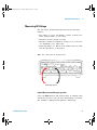
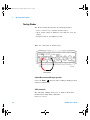
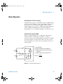
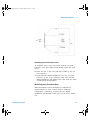
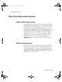
Common mode rejection (CMR)
Ideally, a digital multimeter is completely isolated from
earth- referenced circuits. However, there is a finite
resistance between the digital multimeter's input LO terminal
and earth ground, as shown below. This can cause errors
when measuring low voltages that are floating in relative to
earth ground.
HI
Ideal
Meter
Vtest
Rs
Ci = digital multimeter Input Capacitance
LO
Vf
Ci
Figure 3-1
U2741A User’s Guide
Vf = Float Voltage
Rs = DUT Source Resistance Imbalance
Ri = digital multimeter Isolation Resistance
(LO-Earth)
Ri
V xR
Error (v) = f s
Rs + Ri
Common mode source error
49
User's Guide.book Page 50 Friday, August 8, 2008 9:11 AM
3
Measurement Tutorial
Noise caused by magnetic loops
If you are making measurements near magnetic fields, it is a
good practice to avoid inducing voltages in the measurement
connections. Conductor carrying high current is one common
source of magnetic field. You can use twisted- pair cable
connections to the digital multimeter to reduce the noise
pickup loop area, or place the test leads as close together as
possible. Loose or vibrating test leads will also induce error
voltages. Tie test leads securely when operating near
magnetic fields. Whenever possible, use magnetic shielding
materials or increase the distance from magnetic sources to
minimize this error.
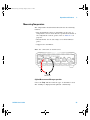
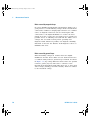
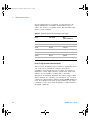
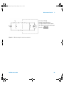
Noise caused by ground loops
When measuring voltages in circuits where the digital
multimeter and the device under test are both referenced to
a common earth ground, a ground loop is formed. As shown
in Figure 3- 2, any voltage difference between the two ground
reference points (Vground) will cause a current to flow
through the measurement leads. This gives rise to noise and
offset voltage (usually power- line related), which are added
to the measured voltage.
50
U2741A User’s Guide
User's Guide.book Page 51 Friday, August 8, 2008 9:11 AM
Measurement Tutorial
RL
HI
Vtest
Ideal
Meter
3
RL = Lead Resistance
Ri = digital multimeter Isolation
Resistance
Vground = Voltage Drop or Ground Bus
RL
LO
Ri > 10GΩ
Vground
Figure 3-2
Ground loop induced error
The best way to eliminate ground loops is to isolate the
digital multimeter from earth by not grounding the input
terminals. If the digital multimeter must be earth- referenced,
connect it and the device under test to the same common
ground point. Also connect the digital multimeter and device
under test to the same electrical outlet whenever possible.
U2741A User’s Guide
51
User's Guide.book Page 52 Friday, August 8, 2008 9:11 AM
3
Measurement Tutorial
Resistance Measurement Considerations
When measuring resistance, the test current flows from the
input HI terminal through the resistor being measured. The
voltage drop across the resistor being measured is sensed
internally in the digital multimeter. Therefore, the test lead
resistance is also measured.
The errors mentioned earlier in this chapter for DC voltage
measurements also apply to resistance measurements.
Additional error sources unique to resistance measurements
are discussed here.
Resistance Measurements
The Agilent U2741A offers two methods for measuring
resistance:
2- wire and 4- wire ohms. For both methods, the test current
flows from the input HI terminal and then through the
resistor being measured. For 2- wire ohms, the voltage drop
across the resistor being measured is sensed internal to the
digital multimeter. Therefore, test lead resistance is also
measured. For 4- wire ohms, separate “sense” connections
are required. Since no current flows in the sense leads, the
resistance in these leads does not give a measurement error.
The errors mentioned earlier in this chapter for dc voltage
measurements also apply to resistance measurements.
Additional error sources unique to resistance measurements
are discussed on the following pages.
4-Wire Ohms Measurements
The 4- wire ohms method provides the most accurate way to
measure small resistances. Test lead resistances and contact
resistances are automatically reduced using this method.
Four- wire ohms is often used in automated test applications
where long cable lengths, numerous connections, or switches
exist between the digital multimeter and the
device- under- test. The recommended connections for 4- wire
ohms measurements are shown below.
52
U2741A User’s Guide
User's Guide.book Page 53 Friday, August 8, 2008 9:11 AM
Measurement Tutorial
3
Removing test lead resistance errors
To eliminate offset errors associated with the test lead
resistance in 2- wire ohms measurements, follow the steps
below.
6 Short the tips of the test leads. The reading is the test
lead resistance.
7 Click Null. The digital multimeter stores the test lead
resistance as the 2- wire resistance null value and the
digital multimeter will subtract this value from the value
of subsequent measurements.
Minimizing power dissipation effects
When measuring resistors designed for temperature
measurements (or other resistive devices with large
temperature coefficients), be aware that the digital
multimeter will dissipate some power in the device under
test.
U2741A User’s Guide
53
User's Guide.book Page 54 Friday, August 8, 2008 9:11 AM
3
Measurement Tutorial
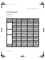
If power dissipation is a problem, you should select the
digital multimeter's next higher measurement range to
reduce the errors to acceptable levels. The following table
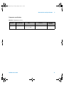
shows several examples:
Table 3-2 Power dissipation for various resistance ranges
Range
Test current
DUT
power at full scale
100 Ω
1 mA
100 mW
1 kΩ
0.83 mA
689 mW
10 kΩ
100 mA
100 mW
100 kΩ
10 mA
10 mW
1 MΩ
900nA
810 nW
10 MΩ
205 nA
420 nW
100 MΩ
205 nA ||10 MΩ
35 nW
Errors in high resistance measurements
When you are measuring large resistances, significant errors
can occur due to insulation resistance and surface
cleanliness. You should take the necessary precautions to
maintain a "clean" high- resistance system. Test leads and
fixtures are susceptible to leakage due to moisture
absorption in insulating materials and "dirty" surface films.
Nylon and PVC are relatively poor insulators (109 Ω) when
compared to Polytetrafluoroethylene (Teflon/PTFE) insulators
(1013 Ω). Leakage from nylon or PVC insulators can easily
contribute a 0.1% error when measuring a 1 MΩ resistance
in humid conditions.
54
U2741A User’s Guide
User's Guide.book Page 55 Friday, August 8, 2008 9:11 AM
Measurement Tutorial
3
AC Measurements
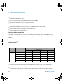
True RMS AC measurements
True RMS responding digital multimeter, like the U2741A,
measure the "heating" potential of an applied voltage. Power
dissipated in a resistor is proportional to the square of the
voltage waveform. This digital multimeter accurately
measures true RMS voltage or current, as long as the wave
shape contains negligible energy above the instrument's
effective bandwidth.
N O TE
The U2741A uses the same techniques to measure true RMS voltage and
true RMS current.
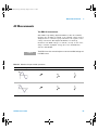
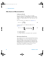
Table 3-3 Waveform shapes and their parameters
Waveform shape
U2741A User’s Guide
Crest factor (CF)
AC RMS
AC+DC RMS
2
V
------2
V-----2
3
V
------3
V
------3
55
User's Guide.book Page 56 Friday, August 8, 2008 9:11 AM
3
Measurement Tutorial
Table 3-3 Waveform shapes and their parameters
Waveform shape
Crest factor (CF)
T
-------tp
AC RMS
V
1 2
-------- × 1 – ⎛ --------⎞
⎝ CF⎠
CF
1
V
AC+DC RMS
V
-------CF
V
The digital multimeter's AC voltage and AC current functions
measure the AC- coupled true RMS value, where only the
"heating value" of only the AC components of the input
waveform is measured while the DC component is rejected.
As seen in the figure above; for sine waves, triangular waves,
and square waves, the AC- coupled and AC+DC values are
equal, since these waveforms do not contain a DC offset.
However, for non- symmetrical waveforms, such as pulse
trains, there is a DC voltage content, which is rejected by
Agilent's AC- coupled true RMS measurements. This can
provide a significant benefit. An AC- coupled true RMS
measurement is desirable when you are measuring small AC
signals in the presence of large DC offsets.
A good example is measuring AC ripples that are present in
DC power supplies. There are situations, however, where you
might want to know the AC+DC true RMS value. You can
determine this value by combining results from DC and AC
measurements, as shown below (Equation ):
( AC + DC ) True RMS =
56
AC 2 + DC 2
(1)
U2741A User’s Guide
User's Guide.book Page 57 Friday, August 8, 2008 9:11 AM
Measurement Tutorial
3
For the best AC noise rejection, you should perform the DC
measurement at 20 NPLC.
True RMS accuracy and high-frequency signal content
A common misconception is that “since an AC digital
multimeter is true RMS, its sine wave accuracy specifications
apply to all waveforms." Actually, the shape of the input
signal can dramatically affect the measurement accuracy
especially when that input signal contains high- frequency
components which exceed the instrument's bandwidth.
U2741A User’s Guide
57
User's Guide.book Page 58 Friday, August 8, 2008 9:11 AM
3
Measurement Tutorial
Other Primary Measurement Functions
Frequency Measurement Errors
The U2741A uses a reciprocal counting technique to measure
frequency. This method generates a constant measurement
resolution for any input frequency. All frequency counters
are susceptible to errors when measuring low- voltage,
low- frequency signals. The effects of both internal noise and
external noise pickup are critical when measuring "slow"
signals. The error is inversely proportional to frequency.
Measurement errors also occur if you attempt to measure
the frequency of an input following a DC offset voltage
change and therefore, you must allow the digital
multimeter’s input to fully settle before making frequency
measurements.
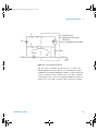
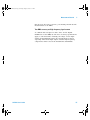
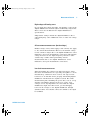
DC Current Measurements
When you connect the digital multimeter in series with a
test circuit to measure current, a measurement error is
introduced. The error is caused by the digital multimeter's
series burden voltage. A voltage is developed across the
wiring resistance and current shunt resistance of the digital
multimeter, as shown below.
58
U2741A User’s Guide
User's Guide.book Page 59 Friday, August 8, 2008 9:11 AM
Measurement Tutorial
Rs
I
Vs
R
Vb
Ideal
Meter
3
Vs = Source Voltage
Rs = DUT Source Resistance
R = digital multimeter Current Shunt
Vb = digital multimeter Burden Voltage
–100% x Vb
Error(%) =
Vs
LO
Figure 3-3
Burden voltage in current measurement
U2741A User’s Guide
59
User's Guide.book Page 60 Friday, August 8, 2008 9:11 AM
3
Measurement Tutorial
Other Sources of Measurement Error
Loading errors (AC volts)
In the AC voltage function, the input of the digital
multimeter appears as a 1 MΩ resistance in parallel with
100 pF of capacitance. The cabling that you use to connect
signals to the digital multimeter also adds capacitance and
loading.
For low frequencies, the loading error is (Equation 2):
– 100 × R s
Error ( % ) = -------------------------R s + 1 MΩ
(2)
At high frequencies, the additional loading error is
(Equation 3):
1
Error ( % ) = 100 × ------------------------------------------------------------- – 1
1 + ( 2π × F × R s × C in )
(3)
Rs = Source resistance
F = Input frequency
Cin = Input capacitance (100 pF) plus cable capacitance
Measurements below full scale
You can make the most accurate AC measurements when the
digital multimeter is at or near the full scale of the selected
range. Autoranging occurs at 10% (down- range) and 120%
(up- range) of full scale. This enables you to measure some
inputs at full scale on one range and 10% of full scale on the
next higher range. In general, the accuracy is better on the
lower range; for the highest accuracy, select the lowest
manual range possible for the measurement.
60
U2741A User’s Guide
User's Guide.book Page 61 Friday, August 8, 2008 9:11 AM
Measurement Tutorial
3
High-voltage self-heating errors
If you apply more than 300 Vrms, self- heating occurs in the
digital multimeter's internal signal- conditioning components.
These errors are included in the digital multimeter's
specifications.
Temperature changes inside the digital multimeter due to
self- heating may cause additional error on other AC voltage
ranges.
AC current measurement errors (burden voltage)
Burden voltage errors, which apply to DC current, also apply
to AC current measurements. However, the burden voltage
for AC current is larger due to the digital multimeter's series
inductance and your measurement connections. The burden
voltage increases as the input frequency increases. Some
circuits may oscillate when performing current
measurements due to the digital multimeter's series
inductance and your measurement connections.
Low-level measurement errors
When measuring AC voltages less than 100 mV, be aware
that these measurements are especially susceptible to errors
introduced by extraneous noise sources. An exposed test
lead acts as an antenna and a properly functioning digital
multimeter will measure the signals received. The entire
measurement path, including the power line, acts as a loop
antenna. Circulating currents in the loop create error
voltages across any impedance in series with the digital
multimeter's input. For this reason, you should apply
low- level AC voltages to the digital multimeter through
shielded cables. You should connect the shield to the input
LO terminal.
U2741A User’s Guide
61
User's Guide.book Page 62 Friday, August 8, 2008 9:11 AM
3
Measurement Tutorial
Make sure the digital multimeter and the AC source are
connected to the same electrical outlet whenever possible.
You should also minimize the area of any ground loops that
cannot be avoided. A high- impedance source is more
susceptible to noise pickup than a low- impedance source.
You can reduce the high- frequency impedance of a source by
placing a capacitor in parallel with the digital multimeter's
input terminals. You may have to experiment to determine
the correct capacitor value for your application.
Most extraneous noise is not correlated with the input
signal. You can determine the error as shown below
(Equation 4):
Voltage Measured =
2
V in + Noise
2
(4)
Correlated noise, while rare, is especially detrimental.
Correlated noise always adds directly to the input signal.
Measuring a low- level signal with the same frequency as the
local power line is a common situation that is prone to this
error.
62
U2741A User’s Guide
User's Guide.book Page 63 Friday, August 8, 2008 9:11 AM
U2741A USB Modular 5.5 Digits Digital Multimeter
User’s Guide
4
Characteristics and Specifications
Product Characteristics 65
Product Specifications 67
This chapter describes the U2741A product characteristics
and operating specifications.
Agilent Technologies
63
User's Guide.book Page 64 Friday, August 8, 2008 9:11 AM
4
Characteristics and Specifications
When using the multimeter in an environment where
electromagnetic interference or significant electrostatic
charge is present, measurement accuracy may be reduced.
N O TE
• The voltage measurement probes are not shielded and can
act as antennas allowing electromagnetic interference to
be added to the signal being measured.
• Electrostatic discharges of 4000 V or greater may cause
the multimeter to temporarily stop responding, resulting
in a lost or erroneous reading.
64
U2741A User’s Guide
User's Guide.book Page 65 Friday, August 8, 2008 9:11 AM
Characteristics and Specifications
4
Product Characteristics
REMOTE INTERFACE
• Hi-Speed USB 2.0
• USBTMC 488.2 Class device
POWER CONSUMPTION
• +12 VDC, 2 A maximum
• Isolated ELV power source
OPERATING ENVIRONMENT
•
•
•
•
STORAGE COMPLIANCE
• –20 °C to +70 °C
• Relative humidity at 5% to 90% RH (non-condensing)
SAFETY COMPLIANCE
Certified with:
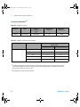
One year specifications full accuracy from 18 °C to 28 °C at 50% RH
Altitude up to 2000 meters
Pollution degree 2
For indoor use only
• IEC 61010-1:2001/EN61010-1:2001 (2nd Edition)
• Canada: CAN/CSA-C22.2 No. 61010-1-04
• USA: ANSI/UL 61010-1:2004
MEASUREMENT COMPLIANCE
CAT II 300 V Over-voltage Protection
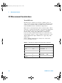
EMC COMPLIANCE
• IEC 61326-2002/EN61326:1997+A1:1998+A2:2001+A3:2003
• Canada: ICES-001:2004
• Australia/New Zealand: AS/NZS CISPR11:2004
COMMON MODE REJECTION
RATIO (CMRR)
• DC CMRR >120 dB with 1k unbalanced load
• AC CMRR >70 dB at 50/60 Hz ±0.1% with 1k unbalanced load
NORMAL MODE REJECTION
RATIO (NMRR)
• >60 dB at 50/60 Hz ±0.1% [1]
• >0 dB at 50/60 Hz ±0.1% [2]
SHOCK AND VIBRATION
Tested to IEC/EN 60068-2
I/O CONNECTOR
Four banana socket terminals
DIMENSIONS (W × D × H)
• 105.00 mm x 175.00 mm x 11.50 mm (without bumpers)
• 117.00 mm x 180.00 mm x 41.00 mm (with bumpers)
WEIGHT
• 451 g (without bumpers)
• 509 g (with bumpers)
WARRANTY
One year
CALIBRATION
Calibration interval of one year is highly recommended
U2741A User’s Guide
65
User's Guide.book Page 66 Friday, August 8, 2008 9:11 AM
4
Characteristics and Specifications
Measurement Category
The U2741A USB modular digital multimeter is intended to be used for measurement in
Measurement Category II, 300 V.
Measurement Category Definition Measurement CAT I is for measurements performed on circuits not directly connected
to MAINS. Examples are measurements on circuits not derived from MAINS, and
specially protected (internal) mains- derived circuits.
Measurement CAT II are measurements performed on circuits directly connected to
the low voltage installation. Examples are measurements on household appliances,
portable tools, and similar equipment.
Measurement CAT III are measurements performed in the building installation.
Examples are measurements on distribution boards, circuit- breakers, wiring, including
cables, bus- bars, junction boxes, switches, socket outlets in the fixed installation, and
equipment for industrial use, and some other equipment including stationary motors
with permanent connection to the fixed installation.
Measurement CAT IV are measurements performed at the source of the low- voltage
installation. Examples are electricity meters and measurements on primary over
current protection devices and ripple control units.
[1] Applicable for NPLC >1
[2] Applicable for NPLC 0.2 and 0.02
66
U2741A User’s Guide
User's Guide.book Page 67 Friday, August 8, 2008 9:11 AM
Characteristics and Specifications
4
Product Specifications
DC specifications [1]
Table 4-1 DC accuracy
Function
Range
Input
impedance
Test current
/Burden voltage,
shunt resistance
Accuracy
(± % of reading + %
of range)
Temperature
Coefficient
0 °C to 18 °C
28 °C to 55°C
Voltage [2]
100.000 mV
10 MΩ
–
0.015 + 0.008
0.002 + 0.0008
1.00000 V
10 MΩ
–
0.015 + 0.005
0.001 + 0.0005
10.0000 V
10 MΩ
–
0.018 + 0.005
0.002 + 0.0005
100.000 V
10 MΩ
–
0.018 + 0.005
0.002 + 0.0005
300.000 V
10 MΩ
–
0.018 + 0.005
0.0015 + 0.0005
10.0000 mA
–
<0.2 V, 10 Ω
0.06 + 0.015
0.005 + 0.0025
100.000 mA
–
<0.2 V, 1 Ω
0.06 + 0.005
0.008 + 0.002
1.00000 A
–
<0.3 V, 0.1 Ω
0.15 + 0.007
0.005 + 0.002
2.0000 A
–
<0.8 V, 0.1 Ω
0.15 + 0.007
0.005 + 0.002
100.000 Ω
–
1.0 mA
0.03 + 0.008
0.006 + 0.0008
1.00000 kΩ
–
1.0 mA
0.03 + 0.005
0.006 + 0.0005
10.0000 kΩ
–
100 μA
0.03 + 0.005
0.006 + 0.0005
100.000 kΩ
–
10.0 μA
0.03 + 0.005
0.006 + 0.0005
1.00000 MΩ
–
1 μA
0.06 + 0.005
0.01 + 0.0005
10.0000 MΩ
–
225 nA
0.25 + 0.005
0.025 +0.0005
100.000 MΩ
–
225 nA
2.0 + 0.005
0.3 + 0.0005
Diode test [5]
1.0000 V
–
1.00 mA
0.015 + 0.03
0.005 + 0.0005
Continuity Test [6]
1.0000 kΩ
–
1.00 mA
0.05 + 0.03
0.005 + 0.0005
Current [3]
Resistance [4]
U2741A User’s Guide
67
User's Guide.book Page 68 Friday, August 8, 2008 9:11 AM
4
Characteristics and Specifications
[1]
Specifications are based on 30 minutes warm-up time, NPLC 20 resolution, and calibration temperature 18 °C to 28 °C.
For NPLC 0 and 0.025, add 0.01% of range.
[2]
120% over range on all ranges except 300 VDC. Input protection up to 300 VDC.
[3]
Input protected with externally accessible 2 A, 250 V fast blown fuse.
[4]
Specifications are for 4-wire ohm or 2-wire ohms using null function in AMM software. If without null function in AMM
software, add 0.2 Ω additional error. Input protection up to 300 VDC. Specifications apply for NPLC ≥1.
[5] Specifications are for the voltage measured at
[6]
the input terminals only.
Continuity threshold is fixed at less than 10 Ω.
DC current settling considerations
Switching current from >1 A to lower current measurement may cause an additional error
approximately 0.3% of reading due to self- heating, and will generally dissipate within a
minute.
AC specifications [1]
Table 4-2 AC accuracy for voltage
Function
Voltage [2]
[1]
Range
Accuracy input (% of reading + % of range)
Frequency (Hz)
20 ~ 45
45 ~ 10k
10k ~ 30k
30k ~ 100k [3]
100.000 mVrms
1 + 0.1
0.2 + 0.1
1.5 + 0.3
5.0 + 0.3
1.00000 V
1 + 0.1
0.2 + 0.1
1.0 + 0.1
3.0 + 0.2
10.0000 V
1 + 0.1
0.3 + 0.1
1.0 + 0.1
3.0 + 0.2
100.000 V
1 + 0.1
0.3 + 0.1
1.0 + 0.1
3.0 + 0.2
250.000 V [4]
1 + 0.1
0.3 + 0.1
1.0 + 0.1
3.0 + 0.2
Specifications are based on 30 minutes warm-up time and calibration temperature 18 ° C to 28 ° C. In manual range, the
settling time is 2.6 seconds while in autorange, the first measurement accuracy is <1%.
[2] Specifications are for sine wave inputs more than 5% of range. 120% over range on all ranges except 250 VAC. Maximum
crest factor of 5 at full scale. Input impedance is 1 MΩ in parallel with capacitance less than 120 pF, AC couple with up to
68
U2741A User’s Guide
User's Guide.book Page 69 Friday, August 8, 2008 9:11 AM
Characteristics and Specifications
4
300 VDC.
[3]
Additional error to be added as frequency more than 30 kHz and signal input less than 10% of range. 30 kHz to 100 kHz:
0.003% of full scale per kHz.
[4]
Input signal has to be more than 50 Vrms.
Table 4-3 Temperature coefficient for voltage
Range
Temperature
coefficient
Frequency (Hz)
100.000 mVrms,
1.00000 V,
10.0000 V,
100.000 V,
250.000 V
20 ~ 45
45 ~ 10k
10k ~ 30k
30k ~ 100k
0.02 + 0.02
0.02 + 0.02
0.05 + 0.02
0.1 + 0.02
Table 4-4 AC accuracy for current [1]
Function
Current [2]
Range
Burden
voltage/
Current shunt
Accuracy input (% of reading + % of range)
Frequency (Hz)
20 ~ 45
45 ~ 1k
1k ~ 10k
10.0000 mA
<0.2 V, 10 Ω
1.5 + 0.1
0.5 + 0.1
2 + 0.2
100.000 mA
<0.2 V, 1 Ω
1.5 + 0.1
0.5 + 0.1
2 + 0.2
1.00000 A
<0.3 V, 0.1 Ω
1.5 + 0.1
0.5 + 0.1
2 + 0.2
2.0000 A
<0.8 V, 0.1 Ω
1.5 + 0.1
0.5 + 0.1
2 + 0.2
[1]
In manual range, the settling time is 2.6 seconds while in autorange, the first measurement accuracy is <1%.
[2]
Input protected with externally accessible 2 A, 250 V fast blown fuse.
Table 4-5 Temperature coefficient for current
Range
Temperature
coefficient
U2741A User’s Guide
10.0000 mA,
100.000 mA,
1.00000 A,
2.0000 A
Frequency (Hz)
20 ~ 45
45 ~ 10k
10k ~ 30k
0.02 + 0.02
0.02 + 0.02
0.02 + 0.02
69
User's Guide.book Page 70 Friday, August 8, 2008 9:11 AM
4
Characteristics and Specifications
Frequency specifications [1]
Table 4-6 Frequency accuracy
Functions
Range
Accuracy
(% of reading + % of
range)
Minimum Input
Frequency
Frequency
20 to 300 kHz
0.0200 +0.003
1 Hz
Temperature
Coefficient (%)
0.005
Table 4-7 Frequency sensitivity for AC voltage
Functions
Input range
Minimum sensitivity (RMS sine wave)
Frequency (Hz)
20 ~ 100 k
100 ~ 300 k
AC Voltage
100 mV [2]
20 mV
20 mV
1V
100 mV
120 mV
10 V
1V
1.2 V
100 V
10 V
20 V
250 V
100 V
120 V
[1] Frequency measurement can only be done in auto range mode. Specifications are for 30 minutes warm-up, using 1
second aperture. Measuring method is using reciprocal counting technique with AC coupled input at AC voltage
function. Gate time of 0.1second or 1second.
[2] Only applicable for square wave measurement.
70
U2741A User’s Guide
User's Guide.book Page 71 Friday, August 8, 2008 9:11 AM
Characteristics and Specifications
4
Temperature specifications
Table 4-8 Temperature accuracy
Function
Thermistor type
Range
Accuracy
Temperature
Coefficient
Temperature
5 kΩ thermistor
–80.0 °C to 150.0 °C
Probe accuracy + 0.2 °C
0.002 °C
–112 °F to 302 °F
U2741A User’s Guide
71
User's Guide.book Page 72 Friday, August 8, 2008 9:11 AM
4
72
Characteristics and Specifications
U2741A User’s Guide
User's Guide.book Page 75 Friday, August 8, 2008 9:11 AM
www.agilent.com
Contact us
To obtain service, warranty or technical
assistance, contact us at the following
phone or fax numbers:
United States:
(tel) 800 829 4444
(fax) 800 829 4433
Canada:
(tel) 877 894 4414
(fax) 800 746 4866
China:
(tel) 800 810 0189
(fax) 800 820 2816
Europe:
(tel) 31 20 547 2111
Japan:
(tel) (81) 426 56 7832 (fax) (81) 426 56
7840
Korea:
(tel) (080) 769 0800
(fax) (080) 769 0900
Latin America:
(tel) (305) 269 7500
Taiwan:
(tel) 0800 047 866
(fax) 0800 286 331
Other Asia Pacific Countries:
(tel) (65) 6375 8100
(fax) (65) 6755 0042
Or visit Agilent World Wide Web at:
www.agilent.com/find/assist
Product specifications and descriptions in
this document are subject to change without notice. Always refer to Agilent web site
for the latest revision.
® Agilent Technologies, Inc. , 2008
First Edition, July 31, 2008
U2741-90001
Agilent Technologies