1
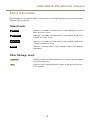
AXIS Q8414–LVS Network Camera
Installation Guide
Legal Considerations
Regulatory Information
Video and audio surveillance can be regulated by laws that
vary from country to country. Check the laws in your local
region before using this product for surveillance purposes.
This product includes one (1) H.264 decoder license and
one (1) AAC decoder license. To purchase further licenses,
contact your reseller.
Europe
Liability
Every care has been taken in the preparation of this
document. Please inform your local Axis office of any
inaccuracies or omissions. Axis Communications AB cannot
be held responsible for any technical or typographical errors
and reserves the right to make changes to the product and
manuals without prior notice. Axis Communications AB
makes no warranty of any kind with regard to the material
contained within this document, including, but not limited
to, the implied warranties of merchantability and fitness for
a particular purpose. Axis Communications AB shall not
be liable nor responsible for incidental or consequential
damages in connection with the furnishing, performance
or use of this material. This product is only to be used for
its intended purpose.
Intellectual Property Rights
Axis AB has intellectual property rights relating to
technology embodied in the product described in this
document. In particular, and without limitation, these
intellectual property rights may include one or more of
the patents listed at www.axis.com/patent.htm and one or
more additional patents or pending patent applications in
the US and other countries.
This product contains licensed third-party software. See
the menu item “About” in the product’s user interface for
more information.
This product contains source code copyright Apple Computer,
Inc., under the terms of Apple Public Source License 2.0
(see www.opensource.apple.com/apsl). The source code is
available from https://developer.apple.com/bonjour/
Equipment Modifications
This equipment must be installed and used in
strict accordance with the instructions given in the
user documentation. This equipment contains no
user-serviceable components. Unauthorized equipment
changes or modifications will invalidate all applicable
regulatory certifications and approvals.
Trademark Acknowledgments
AXIS COMMUNICATIONS, AXIS, ETRAX, ARTPEC and VAPIX
are registered trademarks or trademark applications of Axis
AB in various jurisdictions. All other company names and
products are trademarks or registered trademarks of their
respective companies.
Apple, Boa, Apache, Bonjour, Ethernet, Internet Explorer,
Linux, Microsoft, Mozilla, Real, SMPTE, QuickTime, UNIX,
Windows, Windows Vista and WWW are registered
trademarks of the respective holders. Java and all
Java-based trademarks and logos are trademarks or
registered trademarks of Oracle and/or its affiliates.
UPnPTM is a certification mark of the UPnPTM Implementers
Corporation.
SD, SDHC and SDXC are trademarks or registered trademarks
of SD-3C, LLC in the United States, other countries or both.
Also, miniSD, microSD, miniSDHC, microSDHC, microSDXC
are all trademarks or registered trademarks of SD-3C, LLC
in the United States, other countries or both.
This product complies with the applicable CE marking
directives and harmonized standards:
• Electromagnetic Compatibility (EMC) Directive
2004/108/EC. See Electromagnetic Compatibility (EMC)
on page 2 .
• Low Voltage (LVD) Directive 2006/95/EC. See Safety
on page 3 .
• Restrictions of Hazardous Substances (RoHS) Directive
2011/65/EU. See Disposal and Recycling on page 3 .
A copy of the original declaration of conformity may be
obtained from Axis Communications AB. See Contact
Information on page 3 .
Electromagnetic Compatibility (EMC)
This equipment has been designed and tested to fulfill
applicable standards for:
• Radio frequency emission when installed according to
the instructions and used in its intended environment.
• Immunity to electrical and electromagnetic phenomena
when installed according to the instructions and used
in its intended environment.
USA
This equipment has been tested using a shielded network
cable (STP) and found to comply with the limits for a
Class B digital device, pursuant to part 15 of the FCC
Rules. These limits are designed to provide reasonable
protection against harmful interference in a residential
installation. This equipment generates, uses and can
radiate radio frequency energy and, if not installed and
used in accordance with the instructions, may cause
harmful interference to radio communications. However,
there is no guarantee that interference will not occur in
a particular installation. If this equipment does cause
harmful interference to radio or television reception, which
can be determined by turning the equipment off and on,
the user is encouraged to try to correct the interference by
one or more of the following measures:
• Reorient or relocate the receiving antenna.
• Increase the separation between the equipment and
receiver.
• Connect the equipment into an outlet on a circuit
different from that to which the receiver is connected.
• Consult the dealer or an experienced radio/TV
technician for help.
The product shall be connected using a shielded network
cable (STP) that is properly grounded.
Canada
This digital apparatus complies with CAN ICES-3 (Class B).
The product shall be connected using a shielded network
cable (STP) that is properly grounded.
Cet appareil numérique est conforme à la norme
CAN NMB-3 (classe B). Le produit doit être connecté à
l'aide d'un câble réseau blindé (STP) qui est correctement
mis à la terre.
This product fulfills the requirements for immunity
according to EN 61000-6-1 residential, commercial and
light-industrial environments.
This product fulfills the requirements for immunity
according to EN 61000-6-2 industrial environments.
This product fulfills the requirements for immunity
according to EN 55024 office and commercial environments
Australia/New Zealand
This digital equipment fulfills the requirements for RF
emission according to the Class B limit of AS/NZS CISPR 22.
The product shall be connected using a shielded network
cable (STP) that is properly grounded.
Japan
この装置は、クラスB 情報技術装置です。この装置
は、家庭環境で使用することを目 的としています
が、この装置がラジオやテレビジョン受信機に近
接して使用されると、 受信障害を引き起こすこと
があります。 取扱説明書に従って正しい取り扱い
をして下さい。 本製品は、シールドネットワーク
ケーブル(STP)を使用して接続してください。また
適切に接地してください。
Korea
이 기기는 가정용(B급) 전자파적합기기로서 주로
가정에서 사용하는 것을 목적으로 하며, 모든 지
역에서 사용할 수 있습니다. 적절히 접지된 STP
(shielded twisted pair) 케이블을 사용하여 제품
을 연결 하십시오.
Safety
This product complies with IEC/EN/UL 60950-1, Safety of
Information Technology Equipment. If its connecting cables
are routed outdoors, the product shall be grounded either
through a shielded network cable (STP) or other appropriate
method.
Disposal and Recycling
When this product has reached the end of its useful life,
dispose of it according to local laws and regulations. For
information about your nearest designated collection point,
contact your local authority responsible for waste disposal.
In accordance with local legislation, penalties may be
applicable for incorrect disposal of this waste.
Europe
This symbol means that the product shall not be
disposed of together with household or commercial waste.
Directive 2012/19/EU on waste electrical and electronic
equipment (WEEE) is applicable in the European Union
member states. To prevent potential harm to human health
and the environment, the product must be disposed of in
an approved and environmentally safe recycling process.
For information about your nearest designated collection
point, contact your local authority responsible for waste
disposal. Businesses should contact the product supplier for
information about how to dispose of this product correctly.
This product complies with the requirements of
Directive 2011/65/EU on the restriction of the use of
certain hazardous substances in electrical and electronic
equipment (RoHS).
China
This product complies with the requirements of the
legislative act Administration on the Control of Pollution
Caused by Electronic Information Products (ACPEIP).
Contact Information
Axis Communications AB
Emdalavägen 14
223 69 Lund
Sweden
Tel: +46 46 272 18 00
Fax: +46 46 13 61 30
www.axis.com
Support
Should you require any technical assistance, please contact
your Axis reseller. If your questions cannot be answered
immediately, your reseller will forward your queries through
the appropriate channels to ensure a rapid response. If you
are connected to the Internet, you can:
• download user documentation and software updates
• find answers to resolved problems in the FAQ database.
Search by product, category, or phrase
• report problems to Axis support staff by logging in to
your private support area
• chat with Axis support staff (selected countries only)
• visit Axis Support at www.axis.com/techsup/
Learn More!
Visit Axis learning center www.axis.com/academy/ for
useful trainings, webinars, tutorials and guides.
AXIS Q8414–LVS Network Camera
Safety Information
Read through this Installation Guide carefully before installing the product. Keep the Installation
Guide for future reference.
Hazard Levels
DANGER
Indicates a hazardous situation which, if not avoided, will result in
death or serious injury.
WARNING
Indicates a hazardous situation which, if not avoided, could result
in death or serious injury.
CAUTION
Indicates a hazardous situation which, if not avoided, could result
in minor or moderate injury.
NOTICE
TICE
NO
Indicates a situation which, if not avoided, could result in damage
to property.
Other Message Levels
Important
Indicates significant information which is essential for the product
to function correctly.
Note
Indicates useful information which helps in getting the most out
of the product.
5
AXIS Q8414–LVS Network Camera
Safety Instructions
NOTICE
TICE
NO
• The Axis product shall be used in compliance with local laws and regulations.
• Store the Axis product in a dry and ventilated environment.
• Do not install the product on unstable brackets, surfaces or walls.
• Use only applicable tools when installing the Axis product. Excessive force could cause
damage to the product.
• Use only accessories that comply with technical specification of the product. These can be
provided by Axis or a third party.
• Use only spare parts provided by or recommended by Axis.
• Do not attempt to repair the product by yourself. Contact Axis support or your Axis
reseller for service matters.
Transportation
NOTICE
TICE
NO
• When transporting the Axis product, use the original packaging or equivalent to prevent
damage to the product.
Battery
The Axis product uses a 3.0 V BR/CR2032 lithium battery as the power supply for its internal
real-time clock (RTC). Under normal conditions this battery will last for a minimum of five years.
Low battery power affects the operation of the RTC, causing it to reset at every power-up. When
the battery needs replacing, a log message will appear in the product’s server report. For more
information about the server report, see the product´s setup pages or contact Axis support.
The battery should not be replaced unless required, but if the battery does need replacing, contact
Axis support at www.axis.com/techsup for assistance.
WARNING
• Risk of explosion if the battery is incorrectly replaced.
• Replace only with an identical battery or a battery which is recommended by Axis.
• Dispose of used batteries according to local regulations or the battery manufacturer's
instructions.
6
AXIS Q8414–LVS Network Camera
Maintenance
NOTICE
TICE
NO
• To clean the Axis product, use soapy water or other multi-purpose cleaning agents (acidic,
alkaline, neutral)* and follow the instructions provided by the manufacturer.
• If required, the Axis product can be cleaned with a water hose. Move the spray in a
side-to-side motion.
* Do not use abrasive cleaning products.
7
8
AXIS Q8414–LVS Network Camera
Installation Guide
This Installation Guide provides instructions for installing AXIS Q8414–LVS Network Camera on your
network. For other aspects of using the product, see the User Manual available at www.axis.com
Installation Steps
1. Make sure the package contents, tools and other materials necessary for the installation
are in order. See page 9 .
2. Study the hardware overview. See page 10.
3. Study the specifications. See page 13.
4. Install the hardware. See page 15.
5. Access the product. See page 25.
Package Contents
•
•
•
•
•
•
•
AXIS Q8414–LVS Network Camera
Washers (for mounting screws)
AXIS Connector Guard A
Installation and Management Software CD
Torx bit TR20
4–pin terminal connector
Printed materials
Installation Guide (this document)
AVHS Authentication key
Optional Accessories
•
AXIS T8642 Mounting Kit A (for installing a PoE Ethernet over Coax Adaptor inside
the camera). See page 22.
• AXIS Door Switch A (for intrusion detection). See page 23.
• AXIS Q8414-LVS Smoked Dome (5 pcs). See page 24.
• AXIS Q8414-LVS IR Window B (solid window without microphone hole; 5 pcs). See
page 24.
• I/O Audio Cable 5m (16 ft.)
For information about available accessories, see www.axis.com
9
AXIS Q8414–LVS Network Camera
Hardware Overview
1
2
3
4
5
6
7
8
9
10
12
1
2
3
4
5
6
7
8
9
10
11
12
13
11
13
Cable gasket (network cable)
Cable gasket (I/O or audio cable)
PoE Class selector *
Network connector
Audio out connector
LED indicators
Audio in connector
I/O connector
Control button
IR window
Microphone
Not used
SD card slot
* Used for switching between PoE Class 2 (limited IR) and PoE Class 3 (full IR). See page 13.
10
AXIS Q8414–LVS Network Camera
LED Indicators
LED
Color
Indication
Network
Green
Steady for connection to a 100 Mbit/s network. Flashes for network
activity.
Amber
Steady for connection to a 10 Mbit/s network. Flashes for network
activity.
Unlit
No network connection.
Green
Steady green for normal operation.
Amber
Steady during startup and when restoring settings.
Red
Slow flash for failed upgrade.
Green
Normal operation.
Amber
Flashes green/amber during firmware upgrade.
Status
Power
Note
• The Status LED can be configured to be unlit during normal operation. To configure, go
to Setup > System Options > Ports & Devices > LED. See the online help for more
information.
• The Status LED can be configured to flash while an event is active.
• The Status LED can be configured to flash for identifying the unit. Go to Setup > System
Options > Maintenance .
Connectors and Buttons
For specifications and operating conditions, see page 13.
Network Connector
RJ45 Ethernet connector with Power over Ethernet (PoE).
NOTICE
TICE
NO
The product shall be connected using a shielded network cable (STP). All cables connecting
the product to the network shall be intended for their specific use. Make sure that the
network devices are installed in accordance with the manufacturer’s instructions. For
information about regulatory requirements, see Electromagnetic Compatibility (EMC) on
page 2 .
11
AXIS Q8414–LVS Network Camera
I/O Connector
Use with external devices in combination with, for example, tampering alarms, motion detection,
event triggering, time lapse recording and alarm notifications. In addition to the 0 V DC reference
point and power (DC output), the I/O connector provides the interface to:
•
•
Digital output – For connecting external devices such as relays and LEDs. Connected
devices can be activated by the VAPIX® Application Programming Interface, output
buttons on the Live View page or by an Action Rule. The output will show as active
(shown under System Options > Ports & Devices) if the alarm device is activated.
Digital input – An alarm input for connecting devices that can toggle between an open
and closed circuit, for example: PIRs, door/window contacts, glass break detectors,
etc. When a signal is received the state changes and the input becomes active (shown
under System Options > Ports & Devices).
Audio Connector
The Axis product has the following audio connectors:
•
•
Audio in (pink) – 3.5 mm input for a mono microphone, or a line-in mono signal.
Audio out (green) – 3.5 mm output for audio (line level) that can be connected to
a public address (PA) system or an active speaker with a built-in amplifier. A stereo
connector must be used for audio out.
For audio in, the left channel is used from a stereo signal.
SD Card Slot
An SD card (not included) can be used for local recording with removable storage. For more
information, see Specifications on page 13.
NOTICE
TICE
NO
To prevent corruption of recordings, the SD card should be unmounted before removal. To
unmount, go to Setup > System Options > Storage > SD Card and click Unmount.
Note
For SD card recommendations see www.axis.com
Control Button
The control button is used for:
•
•
Resetting the product to factory default settings. See page 26.
Connecting to an AXIS Video Hosting System service or AXIS Internet Dynamic DNS
Service. For more information about these services, see the User Manual.
12
AXIS Q8414–LVS Network Camera
Specifications
Operating Conditions
The Axis product is intended for indoor use.
Product
Classification
Temperature
Humidity
AXIS Q8414–LVS
NEMA 250 Type 4X,
IEC/EN 60529 IP66,
Class 4M4
IEC 60721-3-4
0 °C to 50 °C
(32 °F to 122 °F)
10-100% RH
(condensing)
Power Consumption
NOTICE
TICE
NO
Use a limited power source (LPS) with either a rated output power limited to ≤100 W
or a rated output current limited to ≤5 A.
Product
PoE
AXIS Q8414–LVS
Power over Ethernet IEEE 802.3af/802.3at Type
1 Class 2, max. 6.2 W
(limited IR)
Power over Ethernet IEEE 802.3af/802.3at Type
1 Class 3, max. 8.7 W
(full IR)
Connectors
I/O Connector
4-pin terminal block for:
•
•
•
•
4 3 2 1
Auxiliary power (DC output)
Digital Input
Digital Output
0 V DC (-)
Function
Pin
0 V DC (-)
1
Notes
Specifications
0 V DC
13
AXIS Q8414–LVS Network Camera
DC output
2
Can be used to power auxiliary equipment.
Note: This pin can only be used as power out.
3.3 V DC
Max load = 50 mA
Digital Input
3
Connect to pin 1 to activate, or leave floating
(unconnected) to deactivate
0 to max 40 V DC
Digital
Output
4
Connected to pin 1 when activated, floating
(unconnected) when deactivated. If used
with an inductive load, e.g. a relay, a diode
must be connected in parallel with the load,
for protection against voltage transients.
0 to max 40 V DC, open
drain, 100 mA
1
3.3 V max 50 mA
2
3
4
Audio Connector
3.5 mm audio
connectors (stereo)
3
14
2
1
AXIS Q8414–LVS Network Camera
1 Tip
2 Ring
3 Sleeve
Audio Input
Microphone/Line in
Ground
Audio Output
Line out (mono)
Ground
SD Card Slot
Supports SD cards with up to 64 GB of storage. For best recording performance, use an SDHC
or SDXC card with speed class 10.
Install the Hardware
NOTICE
TICE
NO
• The product shall be connected using a shielded network cable (STP). All cables connecting
the product to the midspan shall be shielded (STP) and intended for their specific use.
Make sure that the midspan is properly grounded. For information about regulatory
requirements, see Regulatory Information on page 2 .
• Be careful not to scratch, damage or leave fingerprints on the dome cover because this
could decrease image quality. If possible, keep the protective plastic on the front of the
camera assembly until the installation is complete.
The Axis product can be installed with the cables routed through the wall or ceiling.
Read all the instructions before installing the product. Some installation steps would benefit from
being completed together because they require removal of the camera assembly.
•
•
•
A standard or high capacity SD card (not included) can be used to store recordings locally
in the product. To install an SD card, see page 21.
To route the cables before installing the product, see page 15.
To install the product, see page 16.
Route the cables
1. Measure a triangular area in the corner between the ceiling and the walls.
2. Route the network cable (and the I/O, audio cable if neccessary) through the triangular
area of the wall.
15
AXIS Q8414–LVS Network Camera
70 mm
(2.8 in)
100 mm
(4 in)
Install the Camera Unit
1. Remove the gaskets from the top- and side holes in the back chassis.
2. Position the back chassis in the corner between the ceiling and the walls. Use a pencil to
make marks for the screws through the top- and side holes.
3
1
4
2
5
1
Cable gasket, network
16
AXIS Q8414–LVS Network Camera
2
3
4
5
Cable gasket, I/O
Screw (not included)
Washer
Gasket
3. Drill holes for the screws in the ceiling and in the walls.
4. Plug the gaskets back it into their holes. The gaskets should fit snugly with no folds
or bends.
5. Remove the network cable gasket from the back hole and route the network cable
through this back hole.
6. If applicable: Remove the I/O cable gasket from the back hole and route the I/O cable
through this back hole.
7. Pull the tab on the cable gasket to open it.
8. Attach the AXIS Connector Guard A on top of the RJ45 network connector. Drag the
network cable gasket along the cable and plug the network cable gasket into its hole.
The gasket should fit snugly with no folds or bends.
9. Remove the AXIS Connector Guard A from the top of the RJ45 network connector.
10. If applicable: Pull the I/O cable through the I/O cable gasket before attaching the I/O
connector to the cable. Plug the I/O cable gasket into its hole. The gasket should fit
snugly with no folds or bends.
11. Attach the back chassis to the corner in the wall using screws appropriate for the wall
and ceiling material. The screws should go through the washers and the gaskets to
secure the IP66 sealing.
17
AXIS Q8414–LVS Network Camera
3
1
4
2
5
1
2
3
4
5
Cable gasket, network
Cable gasket, I/O
Screw (not included)
Washer
Gasket
12. For optimized sealing: Apply a strip of flexible gap filler / mastic sealant along the sides
of the back chassis. Ensure that any gaps between the back chassis and the ceiling /
walls are filled.
13. If applicable: Insert an SD card (not included) into the SD card slot on the camera
assembly.
14. If applicable: See Install AXIS T8642 Mounting Kit A (sold separately) on page 22.
15. If applicable: See Install AXIS Door Switch A for intrusion detection (sold separately)
on page 23
16. If applicable: See Install AXIS Q8414-LVS Smoked Dome (sold separately) on page 24.
17. If applicable: See Install AXIS Q8414-LVS IR Window B (sold separately) on page 24.
18. If necessary: Manually adjust the angle of the lens to adapt to the size and shape of the
monitored area. For tilt positions, see Set Up the Field of View on page 20
18
AXIS Q8414–LVS Network Camera
±5°
19. Guide the network cable through the cable tunnel to the back of the camera assembly
and plug the network cable into the network connector.
20. If applicable: Guide the I/O cable through the cable tunnel to the back of the camera
assembly and plug the I/O cable into the I/O connector.
21. Hold the camera assembly so that the IR window on the front is in a six o’clock position,
and place the bottom of the camera assembly against the bottom of the back chassis
opening.
19
AXIS Q8414–LVS Network Camera
22. Fold the top of the camera assembly upwards until the camera assembly is pressed
against the entire rim in the back chassis opening.
Important
Adjust the cable slack so that the cables are not squeezed between the sides of the camera
assembly and the back chassis.
23. Attach the camera assembly to the back chassis using the screws (torque 2.5 Nm).
24. Remove the protective film on the front of the camera assembly.
Set Up the Field of View
Tilt the lens to obtain the optimal field of view that covers as much as possible of the monitored
area.
45°
2.45
m
(8 ft )
1.8 m
(6 ft )
4m
(13 ft
)
20
AXIS Q8414–LVS Network Camera
Maximum Tilt Positions for the Lens
Your tilt position for optimal field of view is found in between the maximum tilt positions.
Tilt
up
45°
2.45
m
(8 ft )
0.7 m
(2 ft 4
in )
Tilt
down
45°
2.45
m
(8 ft )
1.8 m
(6 ft )
2.3 m
(7 ft 4
in )
Install an SD Card
It is optional to install a standard or high capacity SD card (not included), which can be used for
local recording with removable storage.
1. Loosen the screws in the front and remove the camera assembly.
2. Insert an SD card (not included) into the SD card slot.
3. Hold the camera assembly so that the IR window on the front is in a six o’clock position,
and place the bottom of the camera assembly against the bottom of the back chassis
opening.
21
AXIS Q8414–LVS Network Camera
4. Fold the top of the camera assembly upwards until the camera assembly is pressed
against the entire rim in the back chassis opening.
Important
Adjust the cable slack so that the cables are not squeezed between the sides of the camera
assembly and the back chassis.
5. Attach the camera assembly to the back chassis using the screws (torque 2.5 Nm).
NOTICE
TICE
NO
To prevent corruption of recordings, the SD card should be unmounted before it is ejected.
To unmount, go to Setup > System Options > Storage > SD Card and click Unmount.
Install AXIS T8642 Mounting Kit A (sold separately)
This accessory kit contains an Ethernet Over Coax Adaptor that enables camera installers to keep
the legacy coax cabling when converting an analog system to digital. It delivers standard PoE and
centrally-sourced power with no new cables required.
1. Attach the angled BNC connector to the AXIS T8642 device.
2. Plug the network cable into the network connector on the AXIS T8642 device.
3. Guide the other end of the network cable through the cable tunnel to the back of the
camera assembly and plug the network cable into the network connector.
4. Guide the cable ties through the cable tunnels and attach the AXIS T8642 device to
the camera assembly.
22
AXIS Q8414–LVS Network Camera
Install AXIS Door Switch A for intrusion detection (sold separately)
1. On the back of the camera assembly: place the switch in the empty compartment next
to the cable tunnel.
23
AXIS Q8414–LVS Network Camera
2. Attach the switch to the compartment using the screws.
3. Guide the I/O cable through the cable tunnel to the back of the camera assembly.
4. Snip off any excessive length from the I/O cable and fit the I/O connector block to the
I/O cable.
5. Plug the I/O connector block into the I/O connector.
Install AXIS Q8414-LVS Smoked Dome (sold separately)
1. Place the camera assembly with its front down on a raised surface, and ensure that the
dome glass does not touch any objects from this position.
2. Loosen the black screws (T20) that attach the camera holder to the back of the camera
assembly.
3. Unplug the microphone cable from the camera, pull the other end of the microphone
cable through the camera holder and remove the microphone cable from the camera
assembly.
4. Remove the camera holder from the back of the camera assembly.
5. Replace the clear glass dome in the front opening with a smoked glass dome.
6. Plug the microphone cable into the IR light window and drag the other end of the
microphone cable through the camera holder.
7. Place the camera holder in its original position on the back of the camera assembly.
Important
Ensure that the IR light window is positioned in its compartment and that the microphone cable
remains plugged into the IR light window.
8. Drag the microphone cable through the cable tunnel and connect the microphone cable
to the camera.
9. Tighten the black screws (T20, torque 2.5 Nm) to attach the camera holder to the camera
assembly.
Install AXIS Q8414-LVS IR Window B (sold separately)
This accessory kit is suitable for installations that do not require audio. The IR light windows are
not equipped with microphone holes.
1. Place the camera assembly with its front down on a raised surface, and ensure that the
dome glass does not touch any objects from this position.
2. Loosen the black screws (T20) that attach the camera holder to the back of the camera
assembly.
3. Unplug the microphone cable from the camera, pull the other end of the microphone
cable through the camera holder and remove the microphone cable from the camera
assembly.
4. Remove the camera holder from the back of the camera assembly.
24
AXIS Q8414–LVS Network Camera
5. Replace the IR light window in the front opening with an IR light window from the kit.
6. Place the camera holder in its original position on the back of the camera assembly.
Important
Ensure that the IR light window is positioned in its compartment.
7. Tighten the black screws (T20, torque 2.5 Nm) to attach the camera holder to the camera
assembly.
Access the Product
Use the tools provided on the Installation and Management Software CD to assign an IP address,
set the password and access the video stream. This information is also available from the support
pages on www.axis.com/techsup/
Focus & Zoom
Focus and zoom should only be configured when installing or reinstalling the product.
To set focus and zoom:
1. Go to Video & Audio > Focus & Zoom.
2. On the Basic tab, set the zoom level using the slider. The buttons < and > move the zoom
position one step in either direction. The buttons << and >> move the zoom position in
multiple steps in either direction.
3. Click Perform auto focus to focus the camera automatically.
4. If more adjustments are needed, go to the Advanced tab.
Note
• Changing the zoom level moves the focus position. Focus should always be adjusted
after changing the zoom.
• Movements in front of the camera should be avoided during automatic focusing.
On the Advanced tab, focus can be adjusted manually:
1. Click Open iris to open the iris to its maximum position. This gives the smallest depth of
field and provides the best conditions for focusing.
2. Focus is set in the Focus window. Use the mouse to move and resize the focus window.
3. Click in the Focus position bar to focus on a desired location. The buttons < and > move
the focus position one step in either direction. The buttons << and >> move the focus
position in multiple steps in either direction.
4. When satisfied, click Enable iris to enable the iris.
25
AXIS Q8414–LVS Network Camera
Reset to Factory Default Settings
Important
Reset to factory default should be used with caution. A reset to factory default will reset
all settings, including the IP address, to the factory default values.
Note
The installation and management software tools are available on the CD supplied with the
product and from the support pages on www.axis.com/techsup
To reset the product to the factory default settings:
1. Disconnect power from the product.
2. Press and hold the control button and reconnect power. See Hardware Overview on
page 10.
3. Keep the control button pressed for about 15–30 seconds until the status LED indicator
flashes amber.
4. Release the control button. The process is complete when the status LED indicator turns
green. The product has been reset to the factory default settings. If no DHCP server is
available on the network, the default IP address is 192.168.0.90
5. Using the installation and management software tools, assign an IP address, set the
password, and access the video stream.
It is also possible to reset parameters to factory default via the web interface. Go to Setup
> System Options > Maintenance.
Further Information
The User Manual is available at www.axis.com
Visit www.axis.com/techsup to check if there is updated firmware available for your network
product. To see the currently installed firmware version, go to Setup > About.
Visit Axis learning center www.axis.com/academy for useful trainings, webinars, tutorials and
guides.
Warranty Information
For information about Axis’ product warranty and thereto related information, see
www.axis.com/warranty/
26
27
Installation Guide
AXIS Q8414–LVS Network Camera
© Axis Communications AB, 2014
Ver. M1.12
Date: October 2014
Part No. 58121