1
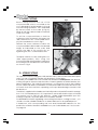
CLICK HERE TO VIEW /
BUY CLARKE SUPPLIES
FROM M&P
300mm
VARIABLE SPEED
METAL LATHE
Model No. CL300M
OPERATING & MAINTENANCE
INSTRUCTIONS
1
1008
SPECIFICATIONS
Motor ..................................................................... 230VAC, 50Hz, 1 Phase
Power Rating ............................................... 300Watts
Current Rating ............................................. 5Amps
Distance Between Dead Centres ...................... 300mm
Centre Height ...................................................... 90mm
Max. Work Diameter ............................................ 180mm
Spindle Bore ......................................................... 20mm
Spindle Taper ........................................................ No.3 Morse Taper
Tailstock Taper ...................................................... No.2 Morse Taper
Cross Slide Travel .................................................. 65mm
Compound Slide Travel ....................................... 55mm (effective)
Spindle Speeds .................................................... 100 to 2,500 RPM
Overall Dimensions .............................................. 820x295x300mm
Weight ................................................................... 40kg
Screw Threads - Imperial .................................... 12 - 104 TPI in 26 steps
Metric ....................................... 0.4 - 2.0mm pitch in 10 steps
SPARE PARTS & SERVICE
For Spare Parts and Servicing, please contact your nearest dealer, or
CLARKE International, on one of the following numbers.
PARTS & SERVICE - 020 8988 7400
e-Mail: [email protected] or [email protected]
Please note that the details and specifications contained herein, are correct at the time of going to print. However, CLARKE International reserve
the right to change specifications at any time without prior notice.
2
TABLE OF CONTENTS
PAGE
Specifications ....................................................................................... 2
Spare Parts & Service .......................................................................... 2
Guarantee ............................................................................................ 5
General Safety Precautions .............................................................. 6
Additional Safety Rules for Metal Lathes .......................................... 7
Features ................................................................................................ 8
The Headstock ............................................................ 9
The Running Gear ....................................................... 9
The Tailstock ................................................................. 9
The Saddle ................................................................. 10
The Motor ................................................................... 10
Unpacking and Preparing for Use ................................................... 11
Installation - Electrical Connections .............................................. 12
Mounting the Lathe ................................................... 12
Starting Procedure ............................................................................. 13
Operation - Simple Turning ............................................................. 15
Using Power Feed ....................................................... 17
Bevel Cutting .............................................................. 18
Screw Cutting ............................................................. 17
Changing Gears for Screw Cutting ................................................. 20
Dial Indicator Table ........................................................................... 20
Gear Charts for Screw Cutting ......................................................... 21
Maintenance ..................................................................................... 23
Settings and Adjustments ................................................................. 23
Accessories ......................................................................................... 25
Parts List ............................................................................................... 27
Parts Diagram .................................................................................... 29
Wiring Diagram .................................................................................. 30
Personal Notes ................................................................................... 31
3
4
INTRODUCTION
Thank you for purchasing this CLARKE 300mm Metal Lathe.
The compact rugged construction and screw cutting capabilities, makes the
CL300M ideal for model makers etc., both professional and DIY alike.
The Machine is capable of turning up to a maximum diameter of 180mm and an
overall length of 300mm. It is further capable of producing short tapers and Imperial
threads, both left and right hand. Metric threads may also be cut with the addition
of a Metric Conversion Kit, available from your Clarke dealer (see ‘Accessories’ for
details).
Before attempting to operate this machine, please read this instruction manual
thoroughly and follow all directions carefully. By doing so you will ensure the safety
of both yourself and others around you, and at the same time you should look
forward to long and trouble free service from your Clarke Metal Lathe.
GUARANTEE
This product is guaranteed against faults in manufacture for 12 months from date
of purchase. Please keep your receipt as it will be required as proof of purchase.
This guarantee is invalid if the product has been found to have been abused or
tampered with in any way, or not used for the purpose for which it was intended.
The reason for return must be clearly stated.
This guarantee does not affect your statutory rights.
IMPORTANT
This manual is intended to instruct the user on the operations peculiar to the
CL300M lathe ONLY. Although some reference is made, and advice given,
regarding various metal turning techniques, it should not be regarded as a
general tutorial on the subject.
It is assumed that the user has some knowledge of machinery of this type, and is
familiar with metal turning. If this is not the case, we strongly advise that he/she
enrol in a course at a local education centre where possible, or seek advice
from a qualified person.
5
GENERAL SAFETY PRECAUTIONS
FOR OPERATING MACHINERY
CAUTION
As with all machinery, there are certain hazards involved with their operation and
use. Exercising respect and caution will considerably lessen the risk of personal
injury. However, if normal safety precautions are overlooked or ignored, personal
injury to the operator or damage to machinery may result.
1. KNOW YOUR MACHINE. Read the manual carefully. Learn the machines applications and limitations, as well as the specific potential hazards peculiar to it.
2. KEEP GUARDS IN PLACE and in working order.
3. EARTH ALL MACHINES. If the machine is equipped with three-pin plug, it should
be plugged into a three-pin electrical socket. Never remove the earth pin.
4. REMOVE ALL ADJUSTING KEYS AND WRENCHES. Form the habit of checking to
ensure that keys, wrenches and tools, are removed from the machine.
5. KEEP WORK AREA CLEAN. Cluttered areas and benches invite accidents.
6. DON’T USE IN DANGEROUS ENVIRONMENT. Don’t use machinery in damp or
wet locations, or expose them to rain. Keep work area well lit.
7. MAKE WORKSHOP CHILDPROOF - with padlocks, master switches or by removing
starter keys.
8. KEEP CHILDREN AND VISITORS AWAY. All children and visitors should be kept a
safe distance from work area
9. DON’T FORCE THE MACHINE. It will do the job better and safer, at the rate for
which it was designed.
10. USE THE RIGHT TOOL. Don’t force a tool or attachment to do a job for which it
was not designed.
11. WEAR PROPER APPAREL. Loose clothing, gloves, neckties, rings, bracelets, or
other jewellery may get caught in moving parts. Nonslip footwear is
recommended. Long hair should be contained.
12. USE SAFETY GLASSES. Everyday eyeglasses only have impact resistant lenses,
they are NOT safety glasses.
13. DON’T OVERREACH. Keep proper footing and balance at all times.
14. MAINTAIN TOOLS IN TOP CONDITION. Keep tools sharp and clean for best and
safest performance. Follow instructions for lubricating and changing accessories.
15. ALWAYS DISCONNECT THE MACHINE before servicing or changing accessories.
16. AVOID ACCIDENTAL STARTING. Switch Machine OFF before plugging in.
17. CHECK FOR DAMAGE. If any part of the machine, (eg. A cover or guard) is
damaged, it should be carefully inspected to ensure that it can perform its
intended function correctly. If in doubt, the part should be renewed. Damage
to moving parts or major components should be Inspected by a qualified
technician before operating the machine. Contact your local dealer for
advice.
6
18. DO NOT STAND ON THE MACHINE. Serious injury could occur if the machine is
tipped over. Do not store materials above or near the machine such that it is
necessary to stand on the machine to get to them.
19. NEVER operate a machine when under the influence of alcohol, drugs or
medication.
20. ALWAYS ENSURE THAT ADEQUATE LIGHTING is available. A minimum intensity of
300 lux should be provided. Ensure that lighting is placed so that you will not be
working in your own shadow.
ADDITIONAL SAFETY RULES FOR METAL LATHES
WARNING:
THIS MACHINE MUST NOT BE MODIFIED OR USED FOR ANY PURPOSE OTHER THAN
THAT FOR WHICH IT IS DESIGNED.
1.
IMPORTANT: You should not operate this machine unless you are thoroughly
familiar with metal turning lathes and turning techniques. If there is any doubt
whatsoever, you should consult a qualified person.
2.
Do not operate the machine until it is completely assembled, and this entire
manual, has been read and understood.
3.
Ensure the proper electrical regulations are followed, and that the machine is
properly earthed.
4.
a. Ensure all chuck keys, spanners and wrenches are removed from the
machine.
b. Examine the setup carefully, ensuring that nothing could possibly interfere
with the rotating workpiece.
c. Ensure the tool post is secure and the cutting tool is adjusted to the correct
height.
d. Ensure your clothing is properly adjusted.
e. Ensure the workpiece is properly secured.
5.
Make all adjustments with the power OFF.
6.
ALWAYS cut at correct speed for the size and type of material being worked.
(Refer to a suitable Turning Manual for cutting speeds)
7.
NEVER leave the lathe unattended whilst it is running.
8.
When you have finished with machine, always remove and store the cutting
tools.
9.
When using a coolant in conjunction with the chip tray, On no account must
suds be allowed to enter the electrical system.
7
FEATURES
23 24
25
1 2
3 4
5
6
7
8
9
Fig. 1
22
10
21
11
26
20 19
18
17
15
16 14
13
12
28
1
27
Rear view of headstock
1.
2.
3.
4.
5.
6.
7.
8.
9.
10.
11.
12.
13.
14.
Headstock
Spindle Flange
Chuck Guard
3- Jaw Chuck
Tool Post
Cross-Slide
Compound Slide
Tailstock Centre
Tailstock
Tailstock Securing Nut
Bed
R.H. Leadscrew Bearing
Compound Slide Feed Handle
Thread Dial Indicator
LEGEND
15.
16.
17.
18.
19.
20.
21.
22.
23.
24.
25.
26.
27.
28.
8
Automatic Feed Lever
Cross-Slide Feed Handle
Apron
Manual (Saddle) Feed Handle
Leadscrew
Motor Brush Cap
Thread Dial Indicator Table
Running Gear Cover
Variable Speed Control Knob
Forward/Off/Reverse Switch
Emergency Stop Switch
High/Low Speed Range Lever
Leadscrew Fwd/Neutral/Rvrse Lever
Overload indicator
THE HEADSTOCK
The motor provides a direct drive to the Spindle via an internal tooth type belt.
Spindle speed is variable, and is regulated by the Speed Control Knob (23), located
on the main control panel.
The spindle, is provided with an internal No.3 Morse taper to accommodate a centre
for use with a face plate or turning clamp, (See ‘Accessories’ on page 24).
The Chuck Guard (3), is an essential component and is mounted on a pin which is
secured to the headstock by two screws. This should always be in place when
using a chuck.
The 3-Jaw, Self Centering Chuck (4) is mounted on the Spindle Flange (2). To remove
the chuck, simply remove the three securing nuts to the rear of the flange allowing
it to be pulled free together with the three mounting studs.
Three external jaws are also supplied which extend the capacity of the chuck.
Their uses and method of assembly is described under ‘Accessories’ on page 24.
The spindle has 6 holes drilled in its flange to accommodate a range of fixtures
such as a Face Plate, 4-Jaw chuck etc., (See ‘Accessories’ on page 24).
THE RUNNING GEAR
The Running Gear, is protected by a cover (22), which is removed by unscrewing
the two securing hex. screws.
Fig 2
The gear train, shown in Fig. 2, transmits drive
to the lead screw. The Lead Screw acts as
a worm and by operating the Auto Feed
Lever (15), which engages a nut with the
lead screw (worm), drive is transmitted to
the saddle, and consequently the cutting
tool, thereby providing a power feed for
screw cutting or general turning operations.
The rotational speed of the lead screw, and
hence the rate of feed of the cutting tool,
is determined by the gear configuration. This
is explained in greater detail under
‘Screwcutting’ on page 17.
27
26
The drive to the leadscrew may be
disconnected by operating the lever (27),
and the same lever is used to drive the
leadscrew in a forward or reverse direction.
(These actions are described in greater
detail under ‘Screwcutting’ on page 17.
THE TAILSTOCK
The Tailstock (9), may be moved along the bed to any desired position and is secured
in position by a single nut (10), at its base. The Tailstock Spindle carries an internal
No.2 Morse taper for use with the Centre (8) provided. A Revolving Centre and Drill
Chuck are also available from your Clarke dealer. (See Accessories on page23).
9
THE SADDLE
The Saddle carries the Cross-Slide (6), on to which is mounted the Compound Slide
(7) with Tool Post (5), allowing intricate and delicate operations to be performed. It
may be driven by the Leadscrew, via a Drive Nut, to provide automatic feed when
the Auto Feed lever (15), mounted on the Apron (17), is operated.
The position of the tool is effected by turning the cross-slide feed handle (16), which
moves it across the lathe, and the saddle or manual feed handle (18), which moves
it longitudinally. Additionally the compound slide feed handle (13) may be used to
move the tool by small amounts at right angles to the cross-slide, or the slide may
be set at an angle to the cross-slide so that short tapers or bevels may be cut. This
is described in greater detail under ‘Bevel Cutting’on page 17.
The cross-slide and compound slide feeds are provided with a scale. These are
used to move the tool by precise amounts - one division being equivalent to 0.001”
(0.025mm). As the feed handle is turned, so does the scale. The scale on the crossslide feed may also be held stationary whilst the handle is turned, allowing the
scale to be ‘zeroed’. The manner in which this is put to use is discussed in greater
detail under ‘Operation’.
Fig. 3
A
The tool post carries 8 hex socket head
screws which are used to secure a cutting
tool in any desired position. Four may be
mounted for convenience and to speed
up your operation. Two are shown
mounted in fig.3.
Tool 1
Tool 2
The tool post is rotated by slackening the
lever (A) on its top, sufficient for the post
to be lifted slightly and then turned to the
desired position.
ALWAYS ensure the post, and hence the
tool, is secured by screwing down the
lever firmly before attempting to cut.
THE MOTOR
It is not recommended that you dis-assemble the motor. Brushes may be replaced
as described under ‘Maintenance’. For all other servicing and repairs, please
contact your Clarke dealer.
OVERLOAD INDICATOR
The overload indicator will light up when
excessive strain is placed on the motor.
If the overload indicator lights up you should,
decrease the amount of material you are
trying to remove.
10
UNPACKING & PREPARING FOR USE
On receipt, carefully unpack the lathe. Inspect to ensure that no damage was
suffered in transit and all parts are accounted for. Should any damage be apparent,
or parts are missing, please contact your Clarke dealer immediately.
The following loose items are to be found in the packing case.
Fig. 4
1. 4 x Rubber Feet.*
9
2. 4 x M6 Pan Head Scews.*
4
11
3. 4 x Hex. Keys.
4. 1 x Chuck Key.
3
5. 1x Plastic Oil Container.*
8
6. 1 x Spare Fuse - 2amp, glass type.*
7. 2 x Plastic Handles w/Nuts and Bolts.*
8. No.2 Morse Taper Centre (for Tailstock).
10
9. 3 x External Jaws (for 3-Jaw Chuck).
10.2 x Double Open Ended Spanners 8x10mm and 14x17mm.
11.1 x Gear Set. Sizes: 30, 35, 40, 40, 45, 50, 55, 57, 60, 65 Teeth.
* denotes not illustrated.
With assistance, considering the weight of the machine, raise it on to a good solid
surface or workbench. Proceed to remove all traces of preservative with paraffin
or good quality solvent, and lightly oil all machined surfaces.
You will notice that, for transit purposes, the cross slide feed handle has been
mounted in reverse. Remove it, by unscrewing the hex. socket head screw securing
it, and mount it the correct way round. Then turn all feed handles to ensure they
are free and move evenly and smoothly.
Attach the plastic handles to the rims of the manual feed and tailstock feed
handwheels respectively, ensuring the nuts are tight and the handles spin freely
about the bolts, without excessive end play.
Saddle, cross-slide and compound slide adjustments are all factory set to ensure
smooth movement in both directions. If however the adjustments have been upset
during transit, indicated by stiff or erratic movement, refer to ‘Settings and
Adjustments’ on page 22 for the methods of adjustment.
All hex. keys and spanners necessary to carry out various adjustments are supplied,
together with a chuck key for the 3-Jaw chuck and a spare 2 Amp fuse. The fuse
holder is located on the main control panel.
The four rubber feet are attached to the underside of the bed, using the four M6
pan head screws, in the tapped holes provided. These screws are also used to
secure the chip tray. We strongly recommend however, that to provide maximum
stability and additional safety, you secure the lathe to a firm foundation as described
under ‘Mounting the lathe’ on page 11.
The three external jaws for the 3-Jaw self centering chuck, extend the capacity of
the chuck, and are discussed in greater detail under ‘Accessories’ on page 24.
11
INSTALLATION
CAUTION!
DO NOT ATTEMPT TO USE THE MACHINE UNTIL INSTALLATION IS COMPLETED, AND
ALL PRELIMINARY CHECKS HAVE BEEN MADE IN ACCORDANCE WITH THIS MANUAL.
A. ELECTRICAL CONNECTIONS
Connect the mains lead to a standard, 230 Volt (50Hz) electrical supply through an
approved 13 amp BS 1363 plug, or a suitably fused isolator switch.
WARNING! THIS APPLIANCE MUST BE EARTHED
IMPORTANT: The wires in the mains lead are coloured in accordance with the
following code:
Green & Yellow
Earth
Blue
Neutral
Brown
Live
As the colours of the flexible lead of this appliance may not correspond with the
coloured markings identifying terminals in your plug proceed as follows:
• Connect GREEN & YELLOW coloured cord to plug terminal marked with a letter
“E” or Earth symbol “ ” or coloured GREEN or GREEN & YELLOW.
• Connect BROWN cord to plug terminal marked with a letter “L” or coloured RED.
• Connect BLUE cord to plug terminal marked with a letter “N” or coloured BLACK.
If this appliance is fitted with a plug which is moulded onto the electric cable (i.e.
non-wirable) please note:
1. The plug must be thrown away if it is cut from the electric cable. There is a
danger of electric shock if it is subsequently inserted into a socket outlet.
2. Never use the plug without the fuse cover fitted.
3. Should you wish to replace a detachable fuse carrier, ensure that the correct
replacement is used (as indicated by marking or colour code).
4. Replacement fuse covers can be obtained from your local dealer or most
electrical stockists.
5. The fuse in the plug must be replaced with one of the same rating (5 amps)
and this replacement must be ASTA approved to BS1362.
B. MOUNTING THE LATHE
The lathe should be mounted on a strong, heavy workbench, of sufficient height
so that you do not need to bend your back to perform normal operations. Take the
necessary precautions when moving the lathe considering its’ weight. Assistance
will be required.
Ensure the location is adequately lit and that you will not be working in your own
shadow.
12
We strongly recommend that the machine is bolted firmly to a strong workbench
using the tapped holes used to secure the feet to the lathe. This is to provide added
stability and consequently, additional safety.
To do this, remove the four M6 screws which
secure the rubber feet and chip tray to the
machine (if already fitted) and discard the
feet.
Drill four M6 clearance holes in a worktop,
at the dimensions shown in the diagram
opposite, and with appropriate length M6
bolts, or screws, with flat washers, (not
supplied) proceed to secure the lathe to the
worktop ensuring the chip tray is in place.
Alternatively, if you do not wish for a permanent installation, you may secure the
lathe to a 5/8” thick plywood board with a minimum recommended dimension of
800 x 300mm, the mounting holes being centralised on the board.
When the lathe is in use, the board should be clamped to workbench using with
‘G’ clamps.
STARTING PROCEDURE
A. DURING INSTALLATION - INITIAL START
(ref. Fig.5)
1. Taking all precautions previously stated, set the High - Low range lever (item 26
page 7)’ to LOW.
2. Ensuring the cross-slide is well away
Fig. 5
from the chuck, and the
D
C
automatic feed lever is in its disengaged position, (i.e. lever is UP),
insert the electric plug into its
socket.
Select FORWARD,using the
Forward/Off/Reverse (F/O/R)
switch (C), on the main control
panel, then release the
Emergency Stop switch by pushing
down on the red knob slightly and
pushing it in towards the headstock,
A
B
as indicated by the arrow on the
top of the red knob (B).
Switch on the machine by GENTLY turning the Variable Speed control knob (A),
clockwise. A click will be heard as power is turned on, but the spindle will not
rotate until the knob is turned clockwise a little further. Speed will increase
progressively the further the knob is turned.
3. Run for a total of 5 minutes during which time gradually increase spindle
speed to its maximum. Run for at at least 2 minutes at this speed before stopping
the machine and disconnecting from the mains supply.
13
Check that all components are still secure and working freely and correctly.
Check also to ensure the mountings are secure.
Repeat the procedure at the HIGH range setting
Should any adjustments be necessary, refer to the appropriate section under
Settings and Adjustments.
NOTE: When changing from HIGH to LOW range, it may be necessary to turn the spindle by
hand, in order for the gears to mesh correctly.
CAUTION:
NEVER attempt to change from HIGH to LOW range with the machine
running.
B. STARTING UNDER NORMAL CONDITIONS
(ref. Fig. 5)
1. Take all necessary precautions previously stated, and ensure the workpiece
can rotate fully without obstruction.
2. Set the Speed Range control lever to HIGH or LOW as required.
3. Set the Forward/Off/Reverse (F/O/R) switch (C), on the main control panel, to
the FORWARD position.
4. Engage or ensure the Auto Feed lever is dis-engaged, depending upon whether
or not automatic feed is required.
IMPORTANT: This should ALWAYS be a deliberate,conscious action.
NOTE: If Auto feed is required, the Leadscrew Forward/Neutral/Reverse Lever should be set
to FORWARD. If Auto feed is not required the lever may be set to Neutral. To do this, grasp the
knurled handle and pull out against spring pressure. Holding the handle in this position,
move the lever until the point, on its end, locates in the middle pit mark in the casing.
5. Proceed to start the machine as described in Section. A above.
6. To stop the machine, turn the Variable Speed Control knob (A) to its OFF position.
If the machine is finished with or is to be left unattended, turn the F/O/R switch
also to the OFF position then disconnect from the mains supply.
CAUTION:
ALWAYS turn the machine OFF at both the Variable Speed Control and the
Forward/Off/ Reverse switch BEFORE attempting to change any settings or make
any adjustments. This includes changing from High to Low range.
14
OPERATION
A. SIMPLE TURNING
Before starting the machine, as described above, it is imperative that the setup for
the type of work to be carried out is fully checked.
Fig 6
The following notes are guidelines as
to how to set up the lathe in order to
carry out a simple turning operation.
ALWAYS plan your work. Have
drawings or a plan on hand together
with any measuring instruments you
may require, such as micrometers/
verniers/calipers etc.
Select a cutting tool that will produce
the desired cut and mount it in the
Tool Rest, with as little overhang as
possible, securing it using three hex
socket head screws in the manner
shown in FIG. 6.
(Ideally, the overhang should be
approx. 10 mm but not more than
15mm for a straight tool).
It is IMPORTANT to ensure that the tip of the cutting tool is on the centre line of the
work, or very slightly below it. On no account should it be above the centre line.
Where necessary shims should be used beneath the tool in order to achieve the
correct height, or, if the tip is too high, the only recourse is to select another tool or
grind down the tip.
To check to ensure the tip is at the correct height, position the tool so that the tip is
almost touching the point of the tailstock centre. They should coincide. If necessary
make adjustments using shims, grind down the cutting tool tip or select another
tool.
When satisfied, mount the work, either in the chuck or on a faceplate, and if
necessary, use the tailstock centre for additional support (If the work cannot be
adequately secured by the chuck, or if it is a long piece, or of small diameter).
Additionally, ‘Steadies’ may be used which are described in greater detail under
‘Accessories’.
If the Tailstock is not to be used, you may remove it completely by slackening off
the securing nut at its base, and sliding it free of the bed.
Mark the surface of the work at the point where the cut is to end, i.e. the shoulder,
using a scriber or similar means, and move the saddle so that the cutting tool is
directly opposite the mark, then wind in the cross-slide so that the tool touches the
surface of the work.
Whilst carrying out these manouvres, rotate the chuck by hand to ensure that
nothing will come into contact with it when turning takes place, i.e. there is adequate
clearance between the saddle, cross-slide, tool post or cutting tool, and the chuck.
15
It may be necessary to adjust the position of the compound slide or reposition the
work in the chuck to guarantee that there is adequate clearance.
Fig 7
When satisfied retract the cutting tool
and wind the saddle away from the
headstock, then wind the cutting tool
up to the work, somewhere along the
length to be cut, whilst rotating the
work by hand, using the chuck.
Continue to advance the cutting tool
slowly, until it just touches the surface.
Record this position by zeroing the
scale on the cross-slide, i.e. turn the
moveable scale until the zero marks
coincide, (see diagram opposite).
Once zeroed, retract the cross-slide
one complete turn, then move the
saddle until the tool is a short distance
from the right hand edge of the work.
Wind in the cross-slide again one full turn until the zero marks again coincide.
IMPORTANT: If you go past the zero marks, back off again at least one half of a turn,
then slowly bring the marks back together.
Whenever you use the scale, as an indicator, to advance the cross-slide or
compound slide, ALWAYS use this procedure to align the marks. This is to take into
account backlash and other clearances in the gearing and slides etc.
Continue to turn the handle an amount equivalent to your desired depth of cut.
NOTE: We recommend that for rough cutting, you do not exceed 0.010” as your depth of
cut.
The setup is now complete to begin your cutting operation, but before starting,
check the position of:
a.Auto feed lever. Ensure it is in the UP position for manual feed.
b.Forward/Neutral/Reverse leadscrew lever. If Auto feed is not required, set to
‘Neutral’.
c. HIGH/LOW lever. Select required speed range.
Switch the machine ON as described under ‘Starting Procedure’ and slowly feed
the cutting tool into the work using the Manual Feed Handle. Proceed until you
reach the previously marked line on the work, then retract the tool one or two
complete turns on the Cross-Slide feed handle.
Wind the saddle back to the begining then wind the tool the same number of turns
‘IN’, plus the depth of desired cut, and proceed to cut once more.
NOTE: This describes the procedure for general, rough cutting. For other types of cuts finishing, cutting shoulders etc., you should consult a suitable handbook.
16
B. SIMPLE TURNING WITH POWER FEED
The same basic setup is used as described above, except that, before starting, the
Leadscrew F/N/R Lever (25) is set to the ‘Forward’ position and the Auto Feed Lever
(15), is operated in order to drive the saddle.
As mentioned previously, the rotational speed of the leadscrew, and hence the
rate of feed of the tool, is dependant upon the gear configuration of the gear
train.
The feed rate for normal turning is considerably less than that used for screw cutting.
The lathe is factory configured for normal turning, however, if you have been screw
cutting, always remember to reset the gear configuration to that for normal turning.
Please refer to the chart on page 19 which shows the gear configuration, and the
explanation of how to change the gears on the same page.
1. Taking all precautions previously mentioned, position the cutting tool a short
distance to the right of the workpiece with the appropriate depth of cut set on
the cross-slide.
2. Ensure the leadscrew F/N/R lever is set to ‘Forward’ and select ‘Forward on the
Forward/Off/Reverse switch on the main control panel. Release the Emergency
Stop and switch ‘ON’ the speed control knob.
3. Turn the knob to achieve your desired spindle speed, and with your right hand,
push down on the auto feed lever until the nut becomes firmly engaged with
the leadscrew.
IMPORTANT: Your left hand should always be free in order to hit the emergency stop
should it become necessary.
4. Carefully observe the movement of the tool and as it approaches the mark on
the surface, denoting the end of cut, pull the Auto Lever UP sharply and ensure
it stays UP. If a degree of accuracy is required, it is recommended that you
finish the cut by hand.
NOTE: If you require a shoulder with perfectly clean corners,then you need to use an
appropriately shaped tool.
5. Retract the tool one or two complete turns on the cross-slide feed, then wind
the saddle so that the tool is at the start point once again. Advance the tool
the same number of turns, plus the depth of cut, and when ready, push down
the auto feed lever and procede to take another cut.
17
C. BEVEL CUTTING
Fig 8
Bevel cutting involves the use of the
compound slide, which is mounted on the
cross-slide and set at right angles to it for all
normal cutting operations. This is indicated
by the zero mark, on the scale, (B, Fig. 8),
lining up with the mark etched on the body
of the cross-slide.
To set the compound slide so that the
cutting tool will cut a bevel, first retract the
slide, until the two hex. socket head screws
(A), are revealed as shown in Fig 8.
Slacken the screws sufficient to allow the
compound slide to be turned to the desired
angle, as indicated on the scale, and
secure the slide in this position by retightening the hex. socket head screws.
Fig 9
The taper, or bevel, is cut by setting the cross
slide appropriately then using the
compound slide feed handle to advance
the cutting tool in the direction of the arrow
as shown in Fig.9.
D. SCREWCUTTING
This operation requires a degree of skill and accuracy, and should not be attempted
unless you are completely familiar with all aspects of the lathe.
Essentially, the saddle will move towards the headstock under power, the same as
cutting using auto feed, except the rate of feed is greater, as determined by the
gear configuration. The cutting tool therefore, is moving ever closer to the rotating
chuck. Great care and concentration must be exercised to ensure that the two do
not meet when the machine is operating, as the possible damage caused could
be disastrous.
The lathe is supplied with a leadscrew that will produce Imperial Threads in a range
from 12 to 104 threads per inch. It is important to remember that the type of thread
you need to cut, i.e. UNF, BA, BSP, BSW etc., will be totally dependant upon the
cutting tool profile, as profiles differ from thread to thread.
For detailed information regarding screwcutting techniques, cutting tools etc., you
should consult a suitable handbook or obtain advice from a qualified person.
A leadscrew, with corresponding half nuts and thread dial indicator, for the
production of Metric threads is available from your Clarke dealer, see ‘Accessories’
on page 24.
18
The general procedure for screwcutting is as follows:
1. Try to get as much distance from the chuck to the end of the proposed screw
thread as possible, and if your design allows, cut a ‘run-off’ into the work which
is of a smaller diameter than the root diameter of the proposed screw thread.
Note, that for long threads it may be necessary to use ‘steady’s’ (see
‘Accessories’ on page 24).
2. Install the appropriate gears for the thread required, and correctly mount the
cutting tool.
Set your required depth of cut, and position the tool ready to begin cutting.
NOTE: Depth of cut is vitally important and may be calculated or obtained from an
appropriate reference manual.
3. Take all necessary precautions previously stated, and start the machine with
the automatic feed lever in its’ disengaged position (UP).
NOTE: Mounted on the Apron, adjacent to the Auto Feed
Lever, is the Thread Dial Indicator, shown in fig. 10.
This is permanently connected to the leadscrew and
as the leadscrew turns,the ‘dial’ spins. Eight radial
marks are etched on the dial and these are used to
determine the exact position of the leadscrew thread
in relation to the saddle.
Fig 10
Mounted on the front of the gear train cover is the
Indicator Table, which is duplicated on page 20.
The numbers in the ‘SCALE’ column refer to the
numbers on the radial lines on the Indicator Dial.
Therefore, if a 20TPI thread is to be cut for example,
the marks 1,3,5 or 7 may be used. You should now
procede as follows:
4. Observe the spinning Dial. In particular, concentrate on one of the numbered
marks etched on the dial which corresponds to the scale number given in the
Indicator Table.
(In our example, this could be 1,3, 5 or 7)
As your line line passes the mark on the body of the dial indicator, engage the
auto lever sharply and thread cutting will commence.
5. As the tool approaches the end of the desired thread, DISENGAGE THE AUTO
FEED LEVER. Do not switch the machine OFF.
6. Retract the tool, using the cross-slide feed handle, noting the exact position on
the scale and the exact number of turns.
Wind the saddle back to the begining and reset the tool by winding IN the
cross-slide the exact number of turns previously wound OUT and then continue
to wind IN to the desired depth of cut.
7. With the machine still running, observe the dial indicator and as the same
numbered line, passes the mark on the body, engage the auto feed lever once
again. Proceed in this manner until the thread is completed.
Engaging the auto feed lever as your predetermined line on the dial passes the
mark on the body ensures the half nuts of the auto feed mechanism engage in
the same thread on the leadscrew each time, thereby ensuring the cutting
tool is in the same place for each pass which in turn produces a perfect thread.
19
CHANGING GEARS FOR SCREWCUTTING
The leadscrew is driven, via a gear train, by a gear on the spindle. The gear ratio
will therefore determine the rotational speed of the leadscrew with relation to the
spindle. i.e. one turn of the spindle will turn the leadscrew an amount determined
by the gear ratio.
By setting the gears to a known ratio, we can therefore produce threads to a known
size, and as the leadscrew supplied produces Imperial threads, the known values
will be in Threads Per Inch (TPI).
A leadscrew for Metric thread cutting, complete with half nuts is available from
your Clarke dealer.
As previously mentioned, the actual thread produced will be totally dependant
upon the profile of the cutting tool. It is not within the scope of this manual to
provide detailed information regarding types of cutting tool, cutting speeds and
working with various types of material etc., and it is strongly advised that you consult
appropriate handbooks or seek advice from a qualified person.
The chart, on page 20, shows the thread sizes that may be cut using the gear
configuration shown in the corresponding columns.
The factory setup for the lathe provides for normal turning using the power or auto
feed, and the gear configuration is as follows:
Gear A .................
Gear B ..................
Gear C .................
Gear D .................
Fig A
20T
80T
20T
80T
Fig B
20
GEAR CHART FOR CUTTING IMPERIAL THREADS
Threads
Per Inch
INDICATOR TABLE
Gear
A
B
C
D
12
40
65
-
30
13
40
65
60
30
14
40
65
-
35
16
40
65
-
40
18
40
65
-
45
19
40
50
60
57
20
40
65
-
50
22
40
65
-
55
24
40
65
-
60
26
40
60
-
65
28
20
65
-
35
32
20
65
-
40
36
20
65
-
45
38
20
50
60
40
20
65
44
20
48
52
TPI
SCALE
12
1,3,5,7
13
1
14
1,5
16
1~8
18
1,5
19
1
20
1,3,5,7
22
1,5
24
1~8
26
1,5
28
1,3,5,7
32
1~8
36
1,3,5,7
57
38
1,5
-
50
40
1~8
65
-
55
44
1,3,5,7
20
65
-
60
48
1~8
20
60
-
65
52
1,3,5,7
1~8 indicates that any of the
8 lines may be used.
Examples:
1. Ref. Fig A on page 19.
To cut 12 TPI, use
40T in position A,
30T in position D,
use the 65 tooth gear in position B to connect A and D.
2. Ref. Fig B on page 19.
To cut 38 TPI, use
20T in position A
50T in position B
60T in position C
57T in position D
21
In order to change the gears, ensure the machine is switched OFF and disconnected
from the mains supply.
Remove the gear train cover which is secured with two hex. socket head screws.
Gear A may be considered as the Driver, and Gear D as the Driven gear.
When a Simple gear train is configured, as illustrated in Fig. A, page 19, the gear at
B acts as an Idler and its size is therefore irrelevant - any convenient gear will suffice
to connect A and D. This is denoted by a blank space in the column in the gear
chart.
The positions of the shafts carrying gears A and D are fixed, therefore all adjustments
are carried out on the shaft carrying gears B and C and the Adjuster ‘A’, shown in
fig. 11.
1. Unscrew the hex socket head screws,
securing gears A and D, followed by
the screw securing gears B and C.
Fig 11
2. To allow the gears B andC to
disengage completely and to
provide for easier reassembly,
unscrew the nut securing the shaft
carrying B and C, and the nut
securing the adjuster A.
3. Remove the gears, taking care to
retain the small keys on each shaft,
and replace with those necessary to
produce your screw thread. They may
be mounted either way round.
The number of teeth on each gear is
clearly marked.
Replace the securing screws,
ensuring the flat washer bears up
against the gear hub in each case.
NOTE: If a compound gear train is required, as
shown in Fig. B on page 18, ensure the spacer,
which is keyed to the shaft carrying gear D, is
located on the shaft, BEFORE the gear, in order
to align gear D with gear C.
4. Proceed to move the shaft carrying B andC and the adjuster ‘A’ so that all
gears mesh correctly, then tighten the adjuster securing nuts. This may take
one or two attempts but make sure there is as little backlash as possible without
being overtight. (Turn the spindle by hand to test for backlash).
Replace the cover and secure with the two hex socket head bolts.
CAUTION:
NEVER run the machine with the cover removed.
22
MAINTENANCE
For maximum performance, it is essential that the lathe is properly maintained.
BEFORE USE
Always inspect before use. Any damage should be repaired and maladjustments
rectified. Damage to machined surfaces should be repaired with an oil stone. Test
by hand to ensure smooth operation of all parts before use.
Inject a few drops of oil to the oilways at both leadscrew bearings (each end
bracket) and once or twice during the day if used continuously. It will be necessary
to remove the gear train cover in order to oil the left hand bearing.
Inject a few drops also to the compound slide oilway, located on the slides’ top
surface, between the two hex socket head screws.
AFTER USE
Remove all swarf from the machine and thoroughly clean all surfaces. If coolant
has been used, ensure it has completely drained from the tray.
Components should be dry, and all machined surfaces should be lightly oiled.
Always remove cutting tools, and store in a safe place.
Fig. 12
MOTOR BRUSHES
The Motor brushes may be changed by
unscrewing the caps, visible at the front and rear
of the machine, beneath the Headstock, as
shown in Fig. 12
SETTINGS AND ADJUSTMENTS
Occasionally, it may be necessary to readjust various components in order to
maintain optimum performance. The adjustments that may be performed are as
follows:
A. CROSS-SLIDE ADJUSTMENTS
The cross-slide is mounted on a dovetail slide, as shown in fig. 13. Between the
sloping surfaces on one side of the dovetail, a ‘jib strip’ is inserted, which may be
tightened against the dovetail under the influence of three adjuster, or ’jib’ screws,
mounted along its’ length.
The jib screws are to be found on the right hand side of the slide, directly beneath
the compound slide handle. In time, wear will occur on the mating surfaces resulting
in a ‘sloppiness’ of action.
23
To adjust the jib strip, to account for wear and ensure the slide moves evenly and
smoothly, proceed as follows:
1. Slacken off all lock nuts and screw
inthe jib screws evenly, i.e. use the
same torque for each screw. The slide
should be held firmly. Test by trying to
turn the handle, but do not force it.
Fig. 13
2. Screw out each jib screw by one
quarter of a turn ONLY, and nip up the
lock nuts
3. Test again, by turning the handle.
The movement should be even and
smooth along its complete length.
4. If the movement is too slack, screw all adjusters ‘in’ by one eighth of a turn, and
re-try. Similarly, if the movement is too stiff, screw ‘out’ the adjusters by one
eighth of a turn until the correct adjustment is attained.
5
Tighten all lock nuts taking care to ensure you do not move the jib screws whilst
doing so.
6. When completed, retract the slide fully and apply oil to all mating surfaces and
the feed screw thread, then wind the slide back to its normal position.
B. CROSS-SLIDE FEED HANDLE
The cross slide feed should run smoothly, and the scale must rotate with the handle.
If any stiffness occurs, it is probably the result of swarf lodging between the mating
surfaces. Undo the securing hex socket head screw securing the handle. Remove
the handle and pull off the collar with the scale taking great care to retain the
small spring plate which sits in a groove beneath the collar.
Clean the assembly and reassemble in reverse order. It will be necessary to hold the
spring plate in place with a small screwdriver, or similar tool, and pushing down on
it to allow the collar to be correctly located on to the shaft.
C. COMPOUND SLIDE ADJUSTMENTS
Compound slide adjustments are made in the same way as those for the cross-slide.
The jib screws are to be found on the left hand side of the slide, i.e facing the front
of the lathe.
NOTE:
It is important that the cross-slide and compound slide adjustments are correctly carried
out and that there is no ‘sloppiness’ of action. Any maladjustments will have a serious effect
on the quality of your work, as they will all be transferred to the tool tip.
It is vital that there is as little movement of the tool as possible.
24
ACCESSORIES
A range of accessories is available from your Clarke dealer which extends the
versatility of your machine. These are as follows:
1. Independant 4-Jaw Chuck 80mm dia. ................... Part No. . 7610721
2. Face Plate - 160mm dia. ............................................................. 7610723
3. Moving Steady . ........................................................................... 7610724
4. Fixed Steady ................................................................................. 7610722
5. Tailstock Drilling Chuck with a 30mm capacity. ...................... 7610725
6. Headstock Centre (MT3) ............................................................. 7610726
7. Revolving Centre (Tailstock - MT2) ............................................. 7610727
8. 6 Piece Cutting Tool Set. ............................................................. 7610728
Comprising tools for 60o thread cutting,
parting/grooving, facing and general turning work.
(Hex. wrench not shown)
9. Metric Thread Cutting Kit (not shown) ...................................... 7610720
Comprising Leadscrew, Half Nuts and Dial Indicator
25
EXTERNAL JAWS - 3-Jaw Chuck
To change the jaws, insert the chuck key and open the jaws to their fullest extent. It
will then be possible to remove each jaw in turn.
Fig.14
Replace them with the external jaws, noting the
following.
The thread segments of the jaws are progressively
‘stepped’ as shown in fig 14. They are also numbered
1 to 3. This is to take into account the lead of the
screwthread within the chuck. It is therefore
necessary to assemble the jaws in the correct order.
Place them as shown in the fig. 14, and assemble in the same order, clockwise in
the slots in the chuck, turning the chuck key as you insert them. Close the jaws fully
and check to ensure they all meet at the centre. If a jaw is out, open the jaws fully,
and retain pressure on the jaw in question whist turning the chuck key, until it snaps
down into position. Re-check to ensure all jaws meet at the centre.
FIXED AND MOVING STEADIES
Fig 15, illustrates the Fixed Steady (A) and Movong Steady (B) assembled to the
lathe, used to support a long workpiece
Fig 15
26
PARTS LIST
No. Description
1
2
3
4
5
6
7
8
9
10
11
12
13
14
15
16
17
18
Bed Way
Chuck
Spindle
Screw M6x30
Washer M6
Nut M6
Key M5x35
Key M4x8
Screw M5x10
Cover
Ball Bearing
Spacer
Head Stock Casting
H/l Gear 21T/29T
Spacer
Spur Gear 45T
Nut
Set Screw M5x8
1
1
1
3
3
5
1
2
6
2
2
2
1
1
1
1
1
1
HT300M001
HT300M002
HT300M003
HT300M004
HT300M005
HT300M006
HT300M007
HT300M008
HT300M009
HT300M010
HT300M011
HT300M012
HT300M013
HT300M014
HT300M015
HT300M016
HT300M017
HT300M018
19
20
21
22
23
24
25
26
27
28
29
30
31
32
33
34
35
36
37
Steel Ball
Compression Spring
Set Screw M6x6
Retaining Ring M12
Ball Bearings 6201ZZ
H/L Gear 12T/20T
Parellel Key M4x45
H/L Gear Shaft
Pulley
Retaining Ring M10
Timing Belt Lx136
Shifting Fork
Shifting Arm
Shifting Knob
Shifting Lever
Shifting Grip
Handle
Handle Mount
Spring
2
3
3
2
2
1
1
1
1
2
1
1
1
1
1
1
1
1
1
HT300M019
HT300M020
HT300M021
HT300M022
HT300M023
HT300M024
HT300M025
HT300M026
HT300M027
HT300M028
HT300M029
HT300M030
HT300M031
T300M0032
HT300M033
HT300M034
HT300M035
HT300M036
HT300M037
1
1
2
HT300M038
HT300M039
HT300M040
38 Indicator
39 Pinion 25T
40 Support Screw
No. Description
Qty Part No.
41
42
43
44
45
46
47
48
49
50
51
52
53
54
55
56
57
58
59
60
61
62
63
64
65
66
67
68
69
70
71
72
73
74
75
78
79
80
81
82
27
Qty
Pinion 20T
1
Fixed Cover
1
Screw M6x20
2
Screw M5x10
1
Gear 45T
1
Shaft
1
Parallel Key 3x8
1
Mount
1
Screw M5x16
2
Gearwheel 20T
2
Washer M6
6
Screw M6x6
4
Cover
1
Screw M6x45
2
Thread Cutting Chart 1
Screw M5x8
12
Washer M4
2
Bush w/Key
1
Gearwheel 80T
2
Shaft
1
Support Plate
1
Washer M8
3
Nut M8
3
Shaft
1
Dial 16T
1
Shaft
1
Screw M6x16
10
Dial Indicator Body 1
Set Screw M4x10
3
Apron
1
Gib Strip
1
Washer
2
Screw M4
2
Shaft
2
Half Nut Base
2
Groove Cam
1
Handle
1
Shaft
1
Feeding Gear 11T/54T1
Feeding Gear 24T
1
Part No.
HT300M041
HT300M042
HT300M043
HT300M044
HT300M045
HT300M046
HT300M047
HT300M048
HT300M049
HT300M050
HT300M051
HT300M052
HT300M053
HT300M054
HT300M055
HT300M056
HT300M057
HT300M058
HT300M059
HT300M060
HT300M061
HT300M062
HT300M063
HT300M064
HT300M065
HT300M066
HT300M067
HT300M068
HT300M069
HT300M070
HT300M071
HT300M072
HT300M073
HT300M074
HT300M075
HT300M078
HT300M079
HT300M080
HT300M081
HT300M082
Cont.
No. Description
83
84
85
86
87
88
89
90
91
92
93
94
95
96
97
98
99
100
101
102
105
106
107
108
109
110
111
112
113
114
115
116
119
120
121
122
123
124
125
126
127
Qty Part No.
Screw M6x12
4
Wheel
2
Knob
2
Handle
2
Dial
2
Bracket
1
Feeding Screw
1
Nut M5
4
Screw M6x12
6
Slide Plate
2
Saddle
1
Gib Strip
1
Feeding Nut Imperial 1
Swivel Disk
1
Screw M8x20
6
Nut M4
6
Screw M4x16
6
Cross Slide
1
Screw M5x10
2
Screw M5x10
2
Compound Rest (B) 1
Screw M4x16
1
Gib Strip
1
Compound Rest (A) 1
Position Pin
1
Screw M8x25
11
Clamping Lever
1
Tool Rest
1
Stud M10x65
1
Cross Feed Screw
1
Bracket
1
Screw M4x114
2
Nut M18
2
Model Label
1
Indicator Table Label 1
Switch Label
1
Control Box
1
Plug w/Cord
1
Rubber Foot
4
Chip Tray
1
Bracket
1
No. Description
HT300M083
HT300M084
HT300M085
HT300M086
HT300M087
HT300M088
HT300M089
HT300M090
HT300M091
HT300M092
HT300M093
HT300M094
HT300M095
HT300M096
HT300M097
HT300M098
HT300M099
HT300M100
HT300M101
HT300M102
HT300M105
HT300M106
HT300M107
HT300M108
HT300M109
HT300M110
HT300M111
HT300M112
HT300M113
HT300M114
HT300M115
HT300M116
HT300M119
HT300M120
HT300M121
HT300M122
HT300M123
HT300M124
HT300M125
HT300M126
HT300M127
Qty Part No.
128
129
131
132
133
134
135
136
137
138
139
140
141
142
143
144
145
146
148
150
151
152
153
154
155
156
-
Key M3x16
Lead Screw Imperial
Bracket
Plastic Plug
Screw M4x10
Rack
Clamp Plate
Washer M10
Screw M6x16
Tailstock Casting
Tailstock Screw
Bracket
Screw M4x12
Tailstock Quill
Centre
Stud M8x35
Clamp
Handle
Pulley
Motor
Cover
Cable Gland
Rear Splash Guard
F/N/R Label
High - Low Label
Top Warning Label
Gearwheel 30T
Gearwheel 35T
Gearwheel 40T
Gearwheel 45T
Gearwheel 50T
1
1
1
1
5
1
1
1
1
1
1
1
1
1
1
1
1
1
1
1
1
1
1
1
1
1
1
1
2
1
1
HT300M128
HT300M129
HT300M131
HT300M132
HT300M133
HT300M134
HT300M135
HT300M136
HT300M137
HT300M138
HT300M139
HT300M140
HT300M141
HT300M142
HT300M143
HT300M144
HT300M145
HT300M146
HT300M148
HT300M150
HT300M151
HT300M152
HT300M153
HT300M154
HT300M155
HT300M156
HT300M157
HT300M158
HT300M159
HT300M160
HT300M161
-
Gearwheel 55T
Gearwheel 57T
Gearwheel 60T
Gearwheel 65T
External Jaws (set)
3-Jaw Chuck Key
1
1
1
1
1
HT300M162
HT300M163
HT300M164
HT300M165
HT300M166
HT300M167
HT300M168
1
168 Variable Speed
1
Control Knob
169 Fwd/OFF/Rev. Switch 1
170 Emergency Stop Sw. 1
28
HT300M169
HT300M170
PARTS DIAGRAM
29
WIRING DIAGRAM
30
NOTES
31
32