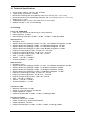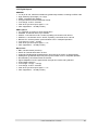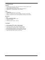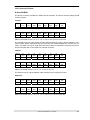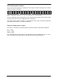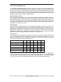
1
User’s Guide
ADI-8 DS Mk III
A true industry standard
SyncAlign
™
™
SyncCheck
™
SteadyClock
Hi-Precision 24 Bit / 192 kHz
Reference Low Latency Conversion
8-Channel Analog <> AES / ADAT Interface
24 Bit / 192 kHz Digital Audio
ADAT <> AES Format Converter
AES-3
24 Bit Interface
Important Safety Instructions ..................................4
General
1
2
3
4
Introduction ...............................................................6
Package Contents .....................................................6
Brief Description and Characteristics.....................6
First Usage – Quick Start
4.1 Controls - Connectors - Displays ............................7
4.2 Quick Start Operation..............................................8
5
Accessories ...............................................................9
6
Warranty...................................................................10
7
Appendix ..................................................................10
Usage and Operation
8
8.1
8.2
8.3
8.4
8.5
8.6
8.7
8.8
Front Panel Controls
A/D Reference......................................................14
A/D State - Meters................................................14
A/D Output ...........................................................14
Patch Mode ..........................................................14
Clock Section .......................................................15
D/A Input ..............................................................16
D/A State - Meters................................................16
D/A Reference......................................................16
Inputs and Outputs
9
Analog Inputs / Outputs
Line In...................................................................18
Line Out................................................................19
10
Digital Inputs / Outputs
10.1 AES / EBU............................................................20
10.2 ADAT Optical .......................................................21
11
Word Clock
11.1 Word Clock Input and Output...............................22
11.2 Technical Description and Background ...............23
11.3 Cables and Termination.......................................24
9.1
9.2
Technical Reference
12
Technical Specifications
12.1 Analog ..................................................................26
12.2 Digital Inputs ........................................................27
12.3 Digital Outputs......................................................28
12.4 Digital ...................................................................28
12.5 Connector Pinouts................................................29
13
Technical Background
13.1 Terminology .........................................................31
13.2 Lock and SyncCheck ...........................................32
13.3 Latency and Monitoring........................................33
13.4 DS – Double Speed .............................................34
13.5 QS – Quad Speed................................................34
13.6 AES/EBU – SPDIF ...............................................35
13.7 Signal to Noise ratio in DS / QS Operation..........36
13.8 SteadyClock .........................................................37
14
Block Diagram .........................................................38
2
User’s Guide ADI-8 DS © RME
Important Safety Instructions
ATTENTION! Do not open chassis – risk of electric shock
The unit has non-isolated live parts inside. No user serviceable parts inside.
Refer service to qualified service personnel.
Mains
• The device must be earthed – never use it without proper grounding
• Do not use defective power cords
• Operation of the device is limited to the manual
• Use same type of fuse only
To reduce the risk of fire or electric shock do not expose this device to rain or
moisture. Prevent moisture and water from entering the device. Never leave
a pot with liquid on top of the device. Do not use this product near water, i. e.
swimming pool, bathtub or wet basement. Danger of condensation inside –
don't turn on before the device has reached room temperature.
Installation
Surface may become hot during operation – ensure sufficient ventilation.
Avoid direct sun light and do not place it near other sources of heat, like radiators or stoves. When mounting in a rack, leave some space between this
device and others for ventilation.
Unauthorized servicing/repair voids warranty. Only use accessories
specified by the manufacturer.
Read the manual completely. It includes all information necessary
to use and operate this device.
User’s Guide ADI-8 DS © RME
3
4
User’s Guide ADI-8 DS © RME
User’s Guide
ADI-8 DS
General
User’s Guide ADI-8 DS © RME
5
1. Introduction
RME's ADI-8 DS is an 8-channel high-end AD/DA converter with a truly unique feature set. The
device combines excellent analog circuit design with the latest generation of outstanding low
latency AD/DA converter chips. Along with its integrated SteadyClock, the ADI-8 DS offers AD
and DA conversion of the highest quality.
When developing the ADI-8 DS we used all our experience, and also the experience of our
customers, to create a unique, excellent and high-quality unit. Although the ADI-8 DS is built to
highest reference standards, it still offers the typical, outstanding price/performance ratio known
from RME. ADI-8 DS features will excite you – but even more the performance and smartness
that it shows in solving any given task. Have fun!
2. Package Contents
Please check that your ADI-8 DS package contains each of the following:
•
•
•
•
ADI-8 DS
Power cord
Manual
1 optical cable (TOSLINK), 2 m
3. Brief Description and Characteristics
The ADI-8 DS is an 8-channel hi-end AD and DA converter in reference quality. In a standard
19" box with 1 unit height the device offers numerous extraordinary features like Intelligent
Clock Control (ICC), SyncCheck, SteadyClock, four hardware reference levels up to +24 dBu,
AES/EBU and ADAT I/O, 192 kHz sample rate, and a digital patch mode.
•
•
•
•
•
•
•
•
•
6
8-channel AD converter, full symmetrical design, 119 dBA
8-channel DA converter, double balanced output, 120 dBA
Low latency conversion: less than 12 samples delay
4 x AES/EBU I/O per D-sub, 8 channels @ 192 kHz
2 x ADAT I/O, 8 channels @ 96 kHz, 4 channels at 192 kHz
Word clock input and output
2 x 8-channel level metering
Noise suppression on power-on and power-off at the analog outputs
Comprehensive digital patch mode for full interconnectivity
User’s Guide ADI-8 DS © RME
4. First Usage – Quick Start
4.1 Controls - Connectors - Displays
The front of the ADI-8 DS features 16 LED level meters, six select keys and 27 LEDs providing
a detailed status display.
The analog input sensitivity can be changed in the area A/D REFERENCE.
In A/D STATE 8 level meters show the digital input level per channel.
The LEDs in A/D OUTPUT indicate which digital output currently carries the signal of the analog
to digital conversion. With Patch Mode active the analog input signal is in some cases not available on the digital outputs ADAT and AES.
The comprehensive PATCH MODE turns the ADI-8 DS into a format converter, distributor and
router, adding many advanced functions to the basic AD and DA conversion.
In the CLOCK SECTION the current clock reference and frequency multiplier is chosen.
The digital input signal of the DA-converters is chosen by pushing the D/A INPUT button.
In D/A STATE 8 level meters show the digital input level per channel.
D/A REFERENCE defines the analog reference level of the analog outputs. This level is
reached at full scale of the DA-converters, thus matching the front panel level meter's level indication.
The rear panel of the ADI-8 DS has eight analog inputs, eight analog outputs, mains power,
word clock I/O, and the digital inputs and outputs AES and ADAT.
ANALOG INPUTS: Eight balanced Line inputs, 1/4" TRS inputs and D-sub.
ANALOG OUTPUTS: Eight balanced Line outputs, 1/4" TRS outputs and D-sub.
AES I/O (25-pin D-sub): The D-sub connector provides four AES/EBU outputs and four
AES/EBU inputs. The 25 pin D-sub connector is wired according to the widely spread Tascam
standard (pinout see chapter 12.5). The AES I/Os are transformer-coupled. The high sensitivity
type input accepts all common digital sources, even SPDIF.
ADAT I/O MAIN (TOSLINK): Standard ADAT optical port.
ADAT I/O AUX (TOSLINK): Transmits further channels at activated sample multiplexing.
WORD IN (BNC): A push switch allows to activate internal termination (75 Ohms).
WORD OUT (BNC): Standard word clock output.
IEC receptacle for power connection. The specially developed, internal hi-performance switch
mode power supply lets the ADI-8 DS operate in the range of 100V to 240V AC. It is shortcircuit-proof, has an integrated line-filter, is fully regulated against voltage fluctuations, and suppresses mains interference.
User’s Guide ADI-8 DS © RME
7
4.2 Quick Start Operation
After connection of all cables and power-on of the device, the configuration of the ADI-8 DS
begins in the CLOCK section. Choose a clock source and a sample rate.
Connect the TRS-jacks or the D-sub connector with the analog signal source. Change the input
sensitivity by pressing A/D REFERENCE until the input level is sufficient to avoid noisy operation. Try to achieve an optimum input level by adjusting the source itself. Raise the source’s
output level until the red Over LED flashes at the loudest parts of the signal, then reduce the
level a bit until no more Overs are detected.
The analog line inputs of the ADI-8 DS can be accessed by using D-sub (for an optional XLR
multicore) and 1/4" TRS jacks. Both are internally connected, so not operational at the same
time. The electronic input stage is built in a servo balanced design which handles unbalanced
(mono TS) and balanced (XLR, stereo TRS jacks) correctly, automatically adjusting the level
reference.
On the DA-side just choose the desired digital input by pressing D/A INPUT. A coarse correction of the analog output level can be done by pressing the D/A REFERENCE button.
The ADI-8 DS stores all current settings and automatically activates them when the device is
turned on.
8
User’s Guide ADI-8 DS © RME
5. Accessories
RME offers several optional components for the ADI-8 DS:
Part Number
Description
OK0050
OK0100
OK0200
OK0300
OK0500
OK1000
Optical cable, Toslink, 0.5 m (1.7 ft)
Optical cable, Toslink, 1 m (3.3 ft)
Optical cable, Toslink, 2 m (6.6 ft)
Optical cable, Toslink, 3 m (9.9 ft)
Optical cable, Toslink, 5 m 16.4 ft)
Optical cable, Toslink, 10 m (32.8 ft)
BO25MXLR4M4F1PRO Digital Breakout Cable Pro, AES/EBU
25-pin D-sub to 4 x XLR male + 4 x XLR female, 1m (3.3 ft)
BO25MXLR4M4F3PRO same, 3 m (9.9 ft)
BO25MXLR4M4F6PRO same, 6 m (19.8 ft)
BO25M25M1PRO
Digital D-sub Cable Pro, AES/EBU,
25-pin D-sub to 25-pin D-sub, 1m (3.3 ft)
BO25M25M3PRO
same, 3m (9.9 ft)
BO25M25M6PRO
same, 6m (19.8 ft)
BO25MXLR8M3
Analog Breakout Cable, 25-pin D-sub to 8 x XLR male, 3 m (9.9 ft)
BO25MXLR8M6
same, 6 m (19.8 ft)
BO25MXLR8M10
same, 10 m (33 ft)
BO25MXLR8F3
Analog Breakout Cable 25-pin D-sub to 8 x XLR female, 3 m (9.9 ft)
BO25MXLR8F6
same, 6 m (19.8 ft)
BO25MXLR8F10
same, 10 m (33 ft)
BOB32
BOB-32, Universal breakout box, 19" 1 Unit height. The professional
digital AES/EBU breakout solution
User’s Guide ADI-8 DS © RME
9
6. Warranty
Each individual ADI-8 DS undergoes comprehensive quality control and a complete test at IMM
before shipping. The usage of high grade components should guarantee a long and trouble-free
operation of the unit.
If you suspect that your product is faulty, please contact your local retailer.
Audio AG grants a limited manufacturer warranty of 6 months from the day of invoice showing
the date of sale. The length of the warranty period is different per country. Please contact your
local distributor for extended warranty information and service. Note that each country may
have regional specific warranty implications.
In any case warranty does not cover damage caused by improper installation or maltreatment replacement or repair in such cases can only be carried out at the owner's expense.
No warranty service is provided when the product is not returned to the local distributor in the
region where the product had been originally shipped.
Audio AG does not accept claims for damages of any kind, especially consequential damage.
Liability is limited to the value of the ADI-8 DS. The general terms of business drawn up by Audio AG apply at all times.
7. Appendix
RME news and further information can be found on our website:
http://www.rme-audio.com
Distributor: Audio AG, Am Pfanderling 60, D-85778 Haimhausen, Tel.: (49) 08133 / 91810
Manufacturer:
IMM Elektronik GmbH, Leipziger Strasse 32, D-09648 Mittweida
Trademarks
All trademarks and registered trademarks belong to their respective owners. RME, Hammerfall
and DIGICheck are registered trademarks of RME Intelligent Audio Solutions. SyncAlign, SyncCheck, ZLM, SteadyClock, ADI-8 DS and Intelligent Clock Control (ICC) are trademarks of RME
Intelligent Audio Solutions. Alesis and ADAT are registered trademarks of Alesis Corp. ADAT
optical is a trademark of Alesis Corp. S/MUX is copyright Sonorus.
Copyright © Matthias Carstens, 10/2012. Version 1.0
All entries in this User’s Guide have been thoroughly checked, however no guarantee for correctness can be given. RME cannot be held responsible for any misleading or incorrect information provided throughout this manual. Lending or copying any part or the complete manual or its
contents as well as the software belonging to it is only possible with the written permission from
RME. RME reserves the right to change specifications at any time without notice.
10
User’s Guide ADI-8 DS © RME
CE / FCC Compliance
CE
This device has been tested and found to comply with the limits of the European Council Directive on the approximation of the laws of the member states relating to electromagnetic compatibility according to RL2004/108/EG, and European Low Voltage Directive RL2006/95/EG.
FCC
This equipment has been tested and found to comply with the limits for a Class B digital device,
pursuant to Part 15 of the FCC Rules. These limits are designed to provide reasonable protection against harmful interference in a residential installation. This equipment generates, uses,
and can radiate radio frequency energy and, if not installed and used in accordance with the
instructions, may cause harmful interference to radio communications. However, there is no
guarantee that interference will not occur in a particular installation. If this equipment does
cause harmful interference to radio or television reception, which can be determined by turning
the equipment off and on, the user is encouraged to try to correct the interference by one or
more of the following measures:
- Reorient or relocate the receiving antenna.
- Increase the separation between the equipment and receiver.
- Connect the equipment into an outlet on a circuit different from that to which the receiver is
connected.
- Consult the dealer or an experienced radio/TV technician for help.
RoHS
This product has been soldered lead-free and fulfils the requirements of the RoHS directive.
ISO 9001
This product has been manufactured under ISO 9001 quality management. The manufacturer,
IMM Elektronik GmbH, is also certified for ISO 14001 (Environment) and ISO 13485 (medical
devices).
Note on Disposal
According to the guide line RL2002/96/EG (WEEE – Directive on Waste
Electrical and Electronic Equipment), valid for all european countries, this
product has to be recycled at the end of its lifetime.
In case a disposal of electronic waste is not possible, the recycling can
also be done by IMM Elektronik GmbH, the manufacturer of the ADI-8 DS.
For this the device has to be sent free to the door to:
IMM Elektronik GmbH
Leipziger Straße 32
D-09648 Mittweida
Germany
Shipments not prepaid will be rejected and returned on the original sender's costs.
User’s Guide ADI-8 DS © RME
11
12
User’s Guide ADI-8 DS © RME
User’s Guide
ADI-8 DS
Usage and Operation
User’s Guide ADI-8 DS © RME
13
8. Front Panel Controls
8.1 A/D Reference
The analog input sensitivity of the AD-converters is referenced to digital
full scale level (0 dBFS). The choices are: +4.2 dBu (-10 dBV compatible),
+13 dBu, +19 dBu and +24 dBu. As the adaptation is performed in the
analog domain, the ADI-8 DS achieves the highest possible values for
Signal to Noise ratio and distortion in any setting.
8.2 A/D State - Meters
The 8 level meters of the D/A STATE show the digital value (dBFS) of the input level per channel. The red LED OVR is lit in half brightness 2 dB before full scale level (-2 dBFS), and full
brightness at 0 dBFS.
8.3 A/D Output
The converted analog input signal is available at the ADAT and AES outputs simultaneously.
When using Patch Mode, one or both of the digital outputs no longer carries the A/D signal, but
a digital input signal (AES or ADAT) instead. The corresponding LED will be off then.
8.4 Patch Mode
Patch Mode controls the direct digital connection
between all I/Os. 8 different modes are available.
Each mode is clearly visualized by 6 LEDs.
Pushing the button repeatedly steps through the
following modes:
Format conversion
1. AES input to ADAT output
2. AES input to AES output
3. ADAT input to ADAT output
4. ADAT input to AES output
Double format conversion, parallel output mode
5. AES input to ADAT and AES output
6. ADAT input to ADAT and AES output
Bi-directional format conversion
7. AES input to ADAT output and ADAT input to AES output
Pass-through mode
8. AES input to AES output and AES input to AES output
Notes:
In modes 1 to 4 AD-conversion is still available on the AES or ADAT output.
In modes 5 to 8 AD-conversion is not available.
In single speed mode, the ADAT output signal is mirrored to the ADAT AUX output, so two
ADAT devices can receive the same signal from the ADI-8 DS. This feature is available in any
mode as long as the unit does not use sample rates higher than 48 kHz.
14
User’s Guide ADI-8 DS © RME
8.5 Clock Section
The source and frequency of the unit's clock is configured in the CLOCK section. The button
CLOCK lets you step through the options external clock (Word, AES, ADAT) and internal clock,
and sets the sample rate range for both an external and the internal clock.
WCK, AES, ADAT
Defines the corresponding input as clock reference. A missing or invalid clock source signal is
indicated by flashing of the corresponding LED.
INT (Master Mode)
Activates the internal clock.
With a setting of INT (internal clock) it is mandatory that the clock rate of the sources is
synchronous to the ADI-8 DS. Therefore the external device has to be synchronized to the
ADI-8 DS word clock output or AES/ADAT output.
The ADI-8 DS thus has to be master, all devices connected to it must be slave. In order to avoid
clicks and drop outs due to faulty or missing synchronicity, a special process called SyncCheck
compares the incoming data and the ADI-8 DS internal clock. The SYNC state is indicated by a
flashing (error) or constantly lit (OK) LED.
44.1, 48
Activates the internal clock at 44.1 kHz or 48 kHz.
DS, QS
With the DS LED additionally lit, the sample rate will be 88.2 or 96 kHz, with QS lit it will be
176.4 or 192 kHz.
A selection of DS and QS is also possible when
using external clock (Slave). If the ADI-8 DS should
operate at 192 kHz, but receives a synchronous
word clock of 48 kHz, the button STATE allows to
activate DS or QS mode. This way, AD-conversion
and digital outputs are configured to operate in the
frequency ranges Single Speed, Double Speed or
Quad Speed.
Using AES as clock source the STATE key is disabled, as the sample rate is clearly given by
the input signal. ADAT misses such information, therefore when ADAT is clock source the
STATE has to be set manually.
Single Speed
All outputs carry a signal in the range of 32 kHz up to 48 kHz.
DS (Double Speed)
The AES outputs 1-8 carry a signal in the range of 64 kHz up to 96 kHz. ADAT stays at no
higher than 48 kHz, with the data transmitted in the S/MUX format.
QS (Quad Speed)
The AES outputs 1-8 carry a signal in the range of 176.4 kHz up to 192 kHz. ADAT stays at no
higher than 48 kHz, with the data transmitted in the S/MUX4 format. Therefore ADAT is limited
to 4 channels (2 per optical output) in this mode.
User’s Guide ADI-8 DS © RME
15
8.6 D/A Input
The button D/A Input selects the signal source of the DA-converters. A
currently active Patch Mode does not disable this function, the DAconversion is always available.
Each input has its own SYNC LED. If a valid input signal is applied,
SyncCheck is automatically active. SyncCheck takes the chosen clock
(internal, external, etc.) as reference and compares it with the input
clocks. Inputs which are not synchronous will be signalled by flashing of
the corresponding SYNC LED.
8.7 D/A State - Meters
The 8 level meters of the D/A STATE show the digital input level per channel as digital value
(dBFS). The yellow 0 dBFS LEDs become active already 2 dB before full scale level (-2 dBFS)
with half brightness, and full brightness at 0 dBFS.
8.8 D/A Reference
The analog output level of the DA-converters is referenced to digital full
scale level (0 dBFS). The choices are: +4.2 dBu (-10 dBV compatible), +13
dBu, +19 dBu and +24 dBu. As the adaptation is performed in the analog
domain, the ADI-8 DS achieves the highest possible values for Signal to
Noise ratio and distortion ratio in any setting.
When selecting +24 dBu the LEDs +19 dBu and +24 dBu are lit at the same
time, indicating that the TRS jacks stay at +19 dBu while the D-sub
connector outputs are operated at +24 dBu.
16
User’s Guide ADI-8 DS © RME
User’s Guide
ADI-8 DS
Inputs and Outputs
User’s Guide ADI-8 DS © RME
17
9. Analog Inputs / Outputs
9.1 Line In
The ADI-8 DS rear has 8 balanced Line inputs, provided by 1/4"
TRS and a 25-pin D-sub connector. Both are internally connected,
so can not be used at the same time. The electronic input stage is
built in a servo balanced design which handles unbalanced (mono
jacks) and balanced (XLR, stereo jacks) signals correctly, automatically adjusting the level reference.
When using unbalanced cables with XLR or TRS connectors be
sure to connect pin 3 (- or ring) to 1 (ground). Otherwise noise may
occur, caused by the unconnected negative input of the balanced
input.
The 25-pin D-sub connector follows the pinout known from devices
manufactured by Tascam (pinout see chapter 12.5). Your local
dealer will supply analog breakout multicores D-sub to XLR in Tascam pinout in different lengths.
The ADI-8 DS uses a completely symmetrical signal path that guarantees an exceptional sound
quality, outstanding low distortion and highest Signal to Noise ratio in all level settings.
One of the main issues when working with an AD-converter is to maintain the full dynamic
range within the best operating level. Therefore the ADI-8 DS internally uses hi-quality electronic switches, which introduce no additional noise or distortion to the audio path. A/D
REFERENCE allows for a perfect adaptation of all 8 channels to the most often used studio
levels.
Each analog input has its own level meter, so every channel can be checked for input signal
and overloads easily. The red LED OVR lights up 2 dB before full scale level (-2 dBFS) with half
brightness, and full brightness at 0 dBFS.
The ADI-8 DS uses the following level references:
Reference
+24
+19
+13
+4.2
0 dBFS @
+24 dBu
+19 dBu
+13 dBu
+4.2 dBu
Headroom @ +4 dBu
20 dB
15 dB
9 dB
12 dB at -10 dBV
Other RME devices
LoGain
+4 dBu
-10 dBV
The setting +4.2 dBu equals -10 dBV with 12 to 15 dB headroom. Set to +24 dBu the ADI-8 DS
is compatible to SMPTE (+24 dBu @ 0 dBFS, +4 dBu with 20 dB of headroom).
18
User’s Guide ADI-8 DS © RME
9.2 Line Out
The ADI-8 DS has 8 balanced Line outputs on the rear,
provided by 1/4" TRS and a 25-pin D-sub connector. They
have their own output drivers respectively and can therefore – in contrary to the inputs – be used simultaneously.
The electronic output stage of the TRS jacks is built in a
servo-balanced design which handles unbalanced (mono
plugs) and balanced (stereo plugs) correctly, automatically adjusting the level reference. The maximum output
level is +21 dBu.
When selecting +24 dBu the LEDs +19 dBu and +24 dBu
are lit at the same time, because the TRS jacks stay at the
+19 setting, while the D-sub connector outputs are operated in the +24 setting.
The electronic output stage of the D-sub connector does not operate servo-balanced! When
connecting unbalanced equipment, make sure pin 3 of the XLR output is not connected. A
connection to ground can cause a higher THD value (higher distortion)!
The 25-pin D-sub connector follows the pinout known from devices manufactured by Tascam
(pinout see chapter 12.5). Your local dealer will supply analog breakout multicores D-sub to
XLR in Tascam pinout in different lengths. The maximum output level at the D-sub connector is
+27 dBu.
Each output channel has its own 7-segment level meter, so every channel can be checked for
output signal and overloads easily. The level data are taken directly in front of the DA-converter.
The yellow 0 dB LEDs light up 2 dB before full scale level (-2 dBFS) with half brightness, and
full brightness at 0 dBFS.
To maintain an optimum level for devices connected to the analog outputs, the ADI-8 DS internally uses hi-quality electronic switches, which introduce no additional noise or distortion to the
audio path. D/A REFERENCE allows for a perfect adaptation of all 8 channels to the most often
used studio levels. The different output levels guarantee optimal conversion results, while still
being compatible to any attached analog equipment.
The ADI-8 DS uses the following level references:
Reference
+24
+19
+13
+4.2
0 dBFS @
+24 dBu
+19 dBu
+13 dBu
+4.2 dBu
Headroom @ +4 dBu
20 dB
15 dB
9 dB
12 dB at -10 dBV
Other RME devices
HiGain
+4 dBu
-10 dBV
The setting +4.2 dBu equals -10 dBV with 12 to 15 dB headroom. Set to +24 dBu the ADI-8 DS
is compatible to SMPTE (+24 dBu @ 0 dBFS, +4 dBu with 20 dB of headroom).
User’s Guide ADI-8 DS © RME
19
10. Digital Inputs / Outputs
10.1 AES/EBU
The four AES/EBU inputs and outputs are provided on the rear of the ADI-8 DS via a 25-pin Dsub connector with Tascam pinout (pinout see chapter 12.5). A digital breakout cable will provide 4 male and 4 female XLR connectors. Every input and output is transformer-balanced and
galvanically isolated.
The inputs can be used in any combination, e. g. it is sufficient to connect an input signal only to
input 3. In slave mode, this input is automatically being used as clock source. If more than one
signal is present, the one furthest left is being used as clock source, i. e. the active input with
the lowest number. Channel Status and Copy bit are ignored.
In standard operation the AES outputs carry the converted analog input signal. When activating
Patch Mode the currently chosen digital input data is present at the outputs instead, see chapter
8.4.
The ADI-8 DS supports Single Wire only, in the range of 32 kHz up to 192 kHz: a total of 8
channels, 2 channels per AES wire. The effective sample frequency equals the clock on the
AES wire. In case a conversion from/to Single, Double and Quad Wire is required, the RME
ADI-192 DD, an 8-channel universal sample rate and format converter, is highly recommended.
Besides the audio data, digital signals in SPDIF or AES/EBU format contain a channel status
coding, which is being used for transmitting further information. The output signal coding of the
ADI-8 DS has been implemented according to AES3-1992 Amendment 4:
• 32 kHz, 44.1 kHz, 48 kHz, 64 kHz, 88.2 kHz, 96 kHz, 176.4 kHz, 192 kHz according to the
current sample rate
• Audio use
• No Copyright, Copy permitted
• Format Professional
• Category General, Generation not indicated
• 2-Channel, No Emphasis
• Aux bits audio use, 24 bit
• Origin: RME
Emphasis
AES/EBU and SPDIF can contain Emphasis information. Audio signals with Emphasis have a
strong high frequency boost and thus require high frequency attenuation on playback.
An Emphasis indication gets lost! This information is neither passed on to the ADAT output,
nor to any of the AES outputs!
Connecting devices with coaxial SPDIF
ports to the ADI-8 DS inputs is accomplished by simple cable adapters
XLR/RCA. To achieve this, pins 2 and 3 of
an XLR plug are being connected to the
two contacts of a Phono/RCA plug. The
ground shield of the cable is only connected to pin 1 of the XLR plug.
The same is true for the outputs, but a male XLR connector is used then. Note that most consumer HiFi equipment with phono SPDIF inputs will only accept signals with Channel Status
‘Consumer’! In such cases the above adapter cable will not work.
20
User’s Guide ADI-8 DS © RME
10.2 ADAT Optical
The ADI-8 DS provides two digital inputs and outputs in ADAT optical format. Using sample
rates up to 48 kHz only the port labelled MAIN is relevant for operation. Higher sample rates
than 48 kHz are realized by sample multiplexing. When using more than four channels at Double Speed or two channels at Quad Speed, the port labelled AUX has to be used as well.
The ADAT optical inputs of the ADI-8 DS use RME's unsurpassed Bitclock PLL, which prevents
clicks and drop outs even in extreme varipitch operation, and guarantees a fast and low jitter
lock to the digital input signal. A usual TOSLINK cable is sufficient for connection.
In Single Speed mode both outputs carry the same audio data. Therefore the output signal can
be sent to two devices at the same time.
In standard operation the ADAT outputs carry the converted analog input signal. When activating Patch Mode the currently chosen digital input data is present at the outputs instead, see
chapter 8.4.
The ADAT outputs can be used in parallel to the AES outputs at up to 192 kHz, but in Quad
Speed mode only channels 1 to 4 will be available.
ADAT MAIN
Interface for the first or only device sending/receiving an ADAT signal. Carries the channels 1 to
8. In S/MUX mode (Double Speed), this port carries the channels 1 to 4. In S/MUX4 mode
(Quad Speed) this port carries channels 1 and 2.
ADAT AUX
Additional port for a transmission of channels 5 to 8 in S/MUX mode, or 3 and 4 in S/MUX4
mode.
With signals encoded as S/MUX, the Clock Section (STATE) has to be switched into DS mode
manually, depending on the current application. Each port carries the data of 4 channels only,
for up to 8 channels MAIN and AUX have to be used.
With signals encoded as S/MUX4, the Clock Section (STATE) has to be switched into QS mode
manually, depending on the current application. Each port carries the data of 2 channels only,
for up to 4 channels MAIN and AUX have to be used.
User’s Guide ADI-8 DS © RME
21
11. Word Clock
11.1 Word Clock Input and Output
Input
The ADI-8 DS word clock input is active when WCK is chosen in the clock section. The signal at
the BNC input can be Single, Double or Quad Speed, the ADI-8 DS automatically adapts to it.
As soon as a valid signal is detected, the WCK LED is constantly lit, otherwise it is flashing.
Thanks to RME's Signal Adaptation Circuit, the word clock input still works correctly even with
heavily mis-shaped, dc-prone, too small or overshoot-prone signals. Thanks to automatic signal
centering, 300 mV (0.3 V) input level are sufficient in principle. An additional hysteresis reduces
sensitivity to 1.0 V, so that over- and undershoots and high frequency disturbances don't cause
a wrong trigger.
The word clock input is shipped as high impedance type (not terminated). A push switch allows
to activate internal termination (75 Ohms). The switch is found on the back beside the BNC
socket. Use a small pencil or similar and carefully push the blue switch so that it snaps into its
lock position and the yellow LED lights up. Another push will release it again and de-activate the
termination.
Output
The ADI-8 DS word clock output is constantly active, providing the current sample frequency as
word clock signal. In master mode, the word clock will be fixed to 44.1 kHz or 48 kHz (DS x 2,
QS x 4). In any other case the sample rate is identical to the one present at the currently chosen clock input. When the current word clock source fails, the last valid sample rate will be held
automatically.
The word clock signal received by the ADI-8 DS can be distributed to other devices by using the
word clock output. Due to its efficient jitter reduction the ADI-8 DS can clean up any clock signal, refresh it, and provide it as reference clock at the BNC output. With this the usual T-adapter
can be avoided, and the ADI-8 DS operates as Signal Refresher. This kind of operation is highly
recommended, because
•
•
•
Input and output are phase-locked and in phase (0°) to each other
SteadyClock removes nearly all jitter from the input signal
the exceptional input (1 Vpp sensitivity instead of the usual 2.5 Vpp, dc cut, Signal Adaptation Circuit) plus SteadyClock guarantee a secure function also with most critical word
clock signals.
Thanks to a low impedance, but short circuit proof output, the ADI-8 DS delivers 4 Vpp to 75
Ohms. For wrong termination with 2 x 75 Ohms (37.5 Ohms), there are still 3.3 Vpp at the output.
22
User’s Guide ADI-8 DS © RME
11.2 Operation and Technical Background
In the analog domain one can connect any device to another device, a synchronization is not
necessary. Digital audio is different. It uses a clock, the sample frequency. The signal can only
be processed and transmitted when all participating devices share the same clock. If not, the
signal will suffer from wrong samples, distortion, crackle sounds and drop outs.
AES/EBU, SPDIF, ADAT and MADI are self-clocking, an additional word clock connection in
principle isn't necessary. But when using more than one device simultaneously problems are
likely to happen. For example any self-clocking will not work in a loop cabling, when there is no
'master' (main clock) inside the loop. Additionally the clock of all participating devices has to be
synchronous. This is often impossible with devices limited to playback, for example CD players,
as these have no SPDIF input, thus can't use the self clocking technique as clock reference.
In a digital studio synchronization is maintained by connecting all devices to a central sync
source. For example the mixing desk works as master and sends a reference signal, the word
clock, to all other devices. Of course this will only work as long as all other devices are
equipped with a word clock or sync input, thus being able to work as slave (some professional
CD players indeed have a word clock input). Then all devices get the same clock and will work
in every possible combination with each other.
Remember that a digital system can only have one master! If the ADI-8 DS uses its internal
clock, all other devices must be set to ‘Slave’ mode.
But word clock is not only the 'great problem solver', it also has some disadvantages. The word
clock is based on a fraction of the really needed clock. For example SPDIF: 44.1 kHz word
clock (a simple square wave signal) has to be multiplied by 256 inside the device using a special PLL (to about 11.2 MHz). This signal then replaces the one from the quartz crystal. Big
disadvantage: because of the high multiplication factor the reconstructed clock will have great
deviations called jitter. The jitter of a word clock is much higher as when using a quartz based
clock.
The end of these problems should have been the so called Superclock, which uses 256 times
the word clock frequency. This equals the internal quartz frequency, so no PLL for multiplying is
needed and the clock can be used directly. But the Superclock proved to be much more critical
than word clock. A square wave signal of 11 MHz distributed to several devices - this simply
means to fight with high frequency technology. Reflections, cable quality, capacitive loads - at
44.1 kHz these factors may be ignored, at 11 MHz they are the end of the clock network. Additionally it was found that a PLL not only generates jitter, but also rejects disturbances. The slow
PLL works like a filter for induced and modulated frequencies above several kHz. As the Superclock is used without any filtering such a kind of jitter and noise suppression is missing.
The actual end of these problems is offered by the SteadyClock technology of the ADI-8 DS.
Combining the advantages of modern and fastest digital technology with analog filter techniques, re-gaining a low jitter clock signal of 22 MHz from a slow word clock of 44.1 kHz is no
problem anymore. Additionally, jitter on the input signal is highly rejected, so that even in real
world usage the re-gained clock signal is of highest quality.
User’s Guide ADI-8 DS © RME
23
11.3 Cabling and Termination
Word clock signals are usually distributed in the form of a network, split with BNC T-adapters
and terminated with resistors. We recommend using off-the-shelf BNC cables to connect all
devices, as this type of cable is used for most computer networks. Actually you will find all the
necessary components (T-adapters, terminators, cables) in most electronics and computer
stores. The latter usually carries 50 Ohm components. The 75 Ohm components used for word
clock are part of video technology (RG59).
Ideally, the word clock signal is a 5 Volt square wave with the frequency of the sample rate, of
which the harmonics go up to far above 500 kHz. To avoid voltage loss and reflections, both the
cable itself and the terminating resistor at the end of the chain should have an impedance of 75
Ohm. If the voltage is too low, synchronization will fail. High frequency reflection effects can
cause both jitter and sync failure.
Unfortunately there are still many devices on the market, even newer digital mixing consoles,
which are supplied with a word clock output that can only be called unsatisfactory. If the output
breaks down to 3 Volts when terminating with 75 Ohms, you have to take into account that a
device, of which the input only works from 2.8 Volts and above, does not function correctly already after 3 meter cable length. So it is not astonishing that because of the higher voltage,
word clock networks are in some cases more stable and reliable if cables are not terminated at
all.
Ideally all outputs of word clock delivering devices are designed as low impedance types, but all
word clock inputs as high impedance types, in order to not weaken the signal on the chain. But
there are also negative examples, when the 75 Ohms are built into the device and cannot be
switched off. In this case the network load is often 2 x 75 Ohms, and the user is forced to buy a
special word clock distributor. Note that such a device is generally recommended for larger
studios.
The ADI-8 DS word clock input can be high-impedance or terminated internally, ensuring maximum flexibility. If termination is necessary (e.g. because the ADI-8 DS is the last device in the
chain), push the switch at the back (see chapter 11.1).
In case the ADI-8 DS resides within a chain of devices receiving word clock, plug a T-adapter
into its BNC input jack, and the cable supplying the word clock signal to one end of the adapter.
Connect the free end to the next device in the chain via a further BNC cable. The last device in
the chain should be terminated using another T-adapter and a 75 Ohm resistor (available as
short BNC plug). Of course devices with internal termination do not need T-adaptor and terminator plug.
Due to the outstanding SteadyClock technology of the ADI-8 DS, we recommend to not
pass the input signal via T-adapter, but to use the ADI-8 DS word clock output instead.
Thanks to SteadyClock, the input signal will both be freed from jitter and - in case of loss or
drop out – be held at the last valid frequency.
24
User’s Guide ADI-8 DS © RME
User’s Guide
ADI-8 DS
Technical Reference
User’s Guide ADI-8 DS © RME
25
12. Technical Specifications
•
•
•
•
•
•
•
Power supply: Internal, 100-240 V AC, 30 Watts
Typical power consumption: 12 Watts
Dimensions including rack ears (WxHxD): 483 x 44 x 242 mm (19" x 1.73" x 9.5")
Dimensions without rack ears/handles (WxHxD): 436 x 44 x 235 mm (17.2" x 1.73" x 9.3")
Weight: 2 kg ( 4.4 lbs)
Temperature range: +5° up to +50° Celsius (41° F up to 122°F)
Relative humidity: < 75%, non condensing
12.1 Analog
Line In 1-8, TRS/D-Sub
• Input: 6.3 mm TRS jack and D-sub 25-pin, servo-balanced
• Input impedance: 10 kOhm
• Input sensitivity switchable +24 dBu, +19 dBu, +13 dBu, +4.2 dBu @ 0 dBFS
AD-Conversion
• Resolution: 24 bit
• Signal to Noise ratio (SNR) @ +24 dBu, 44.1 kHz: 115.0 dB RMS unweighted, 119 dBA
• Signal to Noise ratio (SNR) @ +19 dBu: 114.9 dB RMS unweighted, 118 dBA
• Signal to Noise ratio (SNR) @ +13 dBu: 113.7 dB RMS unweighted, 117 dBA
• Signal to Noise ratio (SNR) @ +4.2 dBu: 109.8 dB RMS unweighted, 113 dBA
• Frequency response @ 44.1 kHz, -0.5 dB: 4 Hz – 20.8 kHz
• Frequency response @ 96 kHz, -0.5 dB: 4 Hz – 45.5 kHz
• Frequency response @ 192 kHz, -1 dB: 2 Hz – 90 kHz
• THD: < -110 dB, < 0.00032 %
• THD+N: < -104 dB, < 0.00063 %
• Channel separation: > 110 dB
DA-Conversion
• Resolution: 24 bit
• Signal to Noise ratio (SNR) @ +24 dBu, 44.1 kHz: 117,0 dB RMS unweighted, 120 dBA
• Signal to Noise ratio (SNR) @ +19 dBu: 117 dB RMS unweighted, 120 dBA
• Signal to Noise ratio (SNR) @ +13 dBu: 117 dB RMS unweighted, 120 dBA
• Signal to Noise ratio (SNR) @ +4.2 dBu: 114 dB RMS unweighted, 117 dBA
• Frequency response @ 44.1 kHz, -0.5 dB: 5 Hz – 22 kHz
• Frequency response @ 96 kHz, -0.5 dB: 5 Hz – 45.9 kHz
• Frequency response @ 192 kHz, -1 dB: 5 Hz - 90 kHz
• THD: < -104 dB, < 0.00063 %
• THD+N: < -102 dB, < 0.0008 %
• Channel separation: > 110 dB
Line Out 1-8, TRS
• Maximum output level: +21 dBu
• Output: 6.3 mm TRS jack, servo-balanced
• Output impedance: 75 Ohm
• Output level switchable +4.2 dBu, +13 dBu, +19 dBu @ 0 dBFS
Line Out 1-8, D-Sub
• Maximum output level: +27 dBu
• Output: D-sub 25-pin, electronically balanced
• Output impedance: 150 Ohm
• Output level switchable +4.2 dBu, +13 dBu, +19 dBu, +24 dBu @ 0 dBFS
26
User’s Guide ADI-8 DS © RME
12.2 Digital Inputs
AES/EBU
• 4 x 25-pin D-sub, transformer-balanced, galvanically isolated, according to AES3-1992
• High-sensitivity input stage (< 0.3 Vpp)
• SPDIF compatible (IEC 60958)
• Accepts Consumer and Professional format
• Lock Range: 27 kHz – 200 kHz
• Jitter when synced to input signal: < 1 ns
• Jitter suppression: > 30 dB (2.4 kHz)
ADAT Optical
• 2 x TOSLINK, according to Alesis specification
• Standard: 8 channels 24 bit, up to 48 kHz
• S/MUX: 2 x 8 channels 24 bit / 48 kHz, equalling 8 channels 24 bit 96 kHz
• S/MUX4: 2 x 8 channels 24 bit / 48 kHz, equalling 4 channels 24 bit 192 kHz
• Bitclock PLL ensures perfect synchronization even in varispeed operation
• Lock range: 31.5 kHz – 54 kHz
• Jitter when synced to input signal: < 1 ns
• Jitter suppression: > 30 dB (2.4 kHz)
Word Clock
• BNC, not terminated (10 kOhm)
• Switch for internal termination 75 Ohm
• Automatic Double/Quad Speed detection and internal conversion to Single Speed
• SteadyClock guarantees super low jitter synchronization even in varispeed operation
• Not affected by DC-offsets within the network
• Signal Adaptation Circuit: signal refresh through auto-center and hysteresis
• Overvoltage protection
• Level range: 1.0 Vpp – 5.6 Vpp
• Lock Range: 27 kHz – 200 kHz
• Jitter when synced to input signal: < 1 ns
• Jitter suppression: > 30 dB (2.4 kHz)
User’s Guide ADI-8 DS © RME
27
12.3 Digital Outputs
AES/EBU
• 4 x, transformer-balanced, galvanically isolated, according to AES3-1992
• Output voltage Professional 4.0 Vpp
• Format Professional according to AES3-1992 Amendment 4
• Single Wire: 4 x 2 channels 24 bit, up to 192 kHz
ADAT
• 2 x TOSLINK
• Standard: 8 channels 24 bit, up to 48 kHz
• S/MUX: 16 channels 24 bit / 48 kHz, equalling 8 channels 24 bit 96 kHz
• S/MUX4: 16 channels 24 bit / 48 kHz, equalling 4 channels 24 bit 192 kHz
Word Clock
• BNC
• Max. output voltage: 5 Vpp
• Output voltage @ 75 Ohm: 4.0 Vpp
• Impedance: 10 Ohm
• Frequency range: 27 kHz – 200 kHz
12.4 Digital
•
•
•
•
•
•
•
Clocks: Internal, AES In, ADAT In, Word Clock In
Low Jitter Design: < 1 ns in PLL mode, all inputs
Internal clock: 800 ps Jitter, Random Spread Spectrum
Jitter suppression of external clocks: > 30 dB (2.4 kHz)
Effective clock jitter influence on AD-conversion: near zero
PLL ensures zero dropout, even at more than 100 ns jitter
Supported sample rates: 28 kHz up to 200 kHz
28
User’s Guide ADI-8 DS © RME
12.5 Connector Pinouts
D-Sub AES/EBU
The D-sub connector provides four AES inputs and outputs. The pinout uses the widely spread
Tascam scheme.
Tascam:
Signal
D-Sub
Signal
D-Sub
In
1/2+
24
In
1/212
In
3/4+
10
In
3/423
In
5/6+
21
In
5/69
In
7/8+
7
In
7/820
Out
1/2+
18
Out
1/26
Out
3/4+
4
Out
3/417
Out
5/6+
15
Out
5/63
Out
7/8+
1
Out
7/814
GND is connected to pins 2, 5, 8, 11, 16, 19, 22, 25. Pin 13 is not connected.
The Yamaha pinout is quite popular as well. When building a D-sub to D-sub adapter or connection cable, please make sure that the connectors are clearly labelled with Tascam and Yamaha. The cable can only be used when the Tascam side is connected to a Tascam connector,
and the Yamaha side is connected to a Yamaha connector.
Yamaha:
Signal
D-Sub
Signal
D-Sub
In
1/2+
1
In
1/214
In
3/4+
2
In
3/415
In
5/6+
3
In
5/616
In
7/8+
4
In
7/817
Out
1/2+
5
Out
1/218
Out
3/4+
6
Out
3/419
Out
5/6+
7
Out
5/620
Out
7/8+
8
Out
7/821
GND is connected to pins 9, 10, 11, 12, 13, 22, 23, 24, 25.
The same is true for a direct adapter cable Tascam D-sub to Euphonix D-sub.
Euphonix:
Signal
D-Sub
Signal
D-Sub
In
1/2+
15
In
1/22
In
3/4+
4
In
3/416
In
5/6+
18
In
5/65
In
7/8+
7
In
7/819
Out
1/2+
21
Out
1/28
Out
3/4+
10
Out
3/422
Out
5/6+
24
Out
5/611
Out
7/8+
13
Out
7/825
GND is connected to pins 3, 6, 9, 12, 14, 17, 20, 23. Pin 1 is not connected.
User’s Guide ADI-8 DS © RME
29
D-Sub Analog Inputs / Outputs
The 25 pin D-sub connectors of analog input and output are wired according to the Tascam
scheme, as shown in this table:
Channel
D-sub
1+
24
112
2+
10
223
3+
21
39
4+
7
420
5+
18
56
6+
4
617
7+
15
73
8+
1
814
GND is connected to pins 2, 5, 8, 11, 16, 19, 22, 25. Pin 13 is unconnected.
The servo balanced input circuitry allows to use unbalanced connections with no loss in level.
For this to work, pins 3 (-) and 1 (GND) have to be connected.
The output circuitry does not operate in a servo-balanced way. When connecting unbalanced
devices make sure that pin 3 (-) stays unconnected.
TRS jacks analog inputs / outputs
The stereo ¼" TRS jacks of the analog inputs are wired according to international standards:
Tip = + (hot)
Ring = – (cold)
Sleeve = GND
The servo-balanced circuitry allows to use monaural TS jacks (unbalanced) with no loss in
level. This is the same as when using a TRS-jack with ring connected to ground.
30
User’s Guide ADI-8 DS © RME
13. Technical Background
13.1 Terminology
Single Speed
Sample rate range originally used in Digital Audio. Typical applications are 32 kHz (digital radio
broadcast), 44.1 kHz (CD), and 48 kHz (DAT).
Double Speed
Doubles the original sample rate range, in order to achieve higher audio quality and improved
audio processing. 64 kHz is practically never used, 88.2 kHz is quite rare in spite of certain advantages. 96 kHz is a common format. Sometimes called Double Fast.
Quad Speed
Controversially discussed way of ensuring hi-end audio quality and processing by quadrupling
the sample frequency. 128 kHz is non-existent, 176.4 kHz is rare, if at all then 192 kHz is used,
e.g. for DVD Audio.
Single Wire
Standard audio data transfer, where the audio signal's sample rate is equal to the rate of the
digital signal. Used from 32 to 192 kHz. Sometimes called Single Wide.
Double Wire
Before 1998 there were no receiver/transmitter circuits available that could receive or transmit
more than 48 kHz. Higher sample rates were transferred by splitting odd and even bits across
the L/R channels of a single AES connection. This provides for twice the data rate, and hence
twice the sample rate. A stereo signal subsequently requires two AES/EBU ports.
The Double Wire method is an industry standard today, however it has a number of different
names, like Dual AES, Double Wide, Dual Line and Wide Wire. The AES3 specification uses
the uncommon term Single channel double sampling frequency mode. When used with the
ADAT format, the term S/MUX is commonly used.
Double Wire not only works with Single Speed signals, but also with Double Speed. As an example, Pro Tools HD, whose AES receiver/transmitter only work up to 96 kHz, uses Double
Wire to transmit 192 kHz. Four channels of 96 kHz turn into two channels of 192 kHz.
Quad Wire
Similar to Double Wire, with samples of one channel spread across four channels. This way
single speed devices can transmit up to 192 kHz, but need two AES/EBU ports to transmit one
channel. Also called Quad AES.
S/MUX
Since the ADAT hardware interface is limited to Single Speed, the Double Wire method is used
for sample rates up to 96 kHz, but usually referred to as S/MUX (Sample Multiplexing). An
ADAT port supports four channels this way.
S/MUX4
The Quad Wire method realizes the transmission of two channels at up to 192 kHz via ADAT.
The method is referred to as S/MUX4.
Note: All conversions of the described methods are lossless. The existing samples are just
spread or re-united between the channels.
User’s Guide ADI-8 DS © RME
31
13.2 Lock and SyncCheck
Digital signals consist of a carrier and the data. If a digital signal is applied to an input, the receiver has to synchronize to the carrier clock in order to read the data correctly. To achieve this,
the receiver uses a PLL (Phase Locked Loop). As soon as the receiver meets the exact frequency of the incoming signal, it is locked. This Lock state remains even with small changes of
the frequency, because the PLL tracks the receiver's frequency.
If an AES signal is applied to the ADI-8 DS, the corresponding LED starts flashing. The unit
indicates LOCK, i. e. a valid input signal (in case the signal is in sync, the LED is constantly lit,
see below).
Unfortunately, LOCK does not necessarily mean that the received signal is correct with respect
to the clock which processes the read out of the embedded data. Example [1]: The ADI-8 DS is
set to 44.1 kHz internal clock (clock mode master), and a mixing desk with AES output is connected to the DS input. The AES LED will start flashing immediately, because the mixing desk's
sample rate is generated internally, and thus slightly higher or lower than the ADI-8 DS' internal
sample rate. Result: When reading out the data, there will frequently be read errors that cause
clicks and drop outs.
Also when using multiple inputs, a simple LOCK is not sufficient. The above described problem
can be solved elegantly by setting the ADI-8 DS from internal clock to AES (its internal clock will
then be the clock delivered by the mixing desk). But in case another asynchronous device is
connected, there will again be a slight difference in the sample rate, and therefore clicks and
drop outs.
In order to display those problems optically at the device, the ADI-8 DS includes SyncCheck. It
checks all clocks used for synchronicity. If they are not synchronous to each other (i. e. absolutely identical), the LED of the asynchronous input flashes. In case they are synchronous the
LED stays dark, only the LED of the current clock source will be constantly lit. In example 1 it
would have been obvious that the AES LED starts flashing after connecting the mixing desk.
In practice, SyncCheck allows for a quick overview of the correct configuration of all digital devices. This way one of the most difficult and error-prone topics of the digital studio world finally
becomes easy to handle.
32
User’s Guide ADI-8 DS © RME
13.3 Latency and Monitoring
The term Zero Latency Monitoring has been introduced by RME in 1998 for the DIGI96 series
and describes the ability to pass-through the computer's input signal at the interface directly to
the output. Since then, the idea behind has become one of the most important features of modern hard disk recording. In the year 2000, RME published two ground-breaking Tech Infos on
the topics Low Latency Background, which are still up-to-date: Monitoring, ZLM and ASIO, and
Buffer and Latency Jitter, found on the RME website.
How much Zero is Zero?
From a technical view there is no zero. Even the analog pass-through is subject to phase errors, equalling a delay between input and output. However, delays below certain values can
subjectively be claimed to be a zero-latency. This applies to analog routing and mixing, and in
our opinion also to RME's Zero Latency Monitoring. RME's digital receiver's buffer and the output via the transmitter cause a typical delay of 3 samples. At 44.1 kHz this equals about 68 µs
(0.000068 s), at 192 kHz only 15 µs.
Oversampling
While the delays of digital interfaces can be disregarded altogether, the analog inputs and outputs do cause a significant delay. Modern converter chips operate with 64 or 128 times oversampling plus digital filtering, in order to move the error-prone analog filters away from the audible frequency range as far as possible. This typically generates a delay of about 40 samples,
equalling one millisecond. A playback and re-record of the same signal via DA and AD (loopback) then causes an offset of the newly recorded track of about 2 ms.
Low Latency!
The ADI-8 DS uses the latest top AD- and DA-converters with special low latency filters, offering exceptional Signal to Noise and distortion figures and a super-fast conversion. A delay of
down to 5 samples had been unavailable a few years back. The exact delays caused by the
AD- and DA-conversion of the ADI-8 DS Mk III are:
Sample frequency kHz
44.1
48
AD (12.6 x 1/fs) ms
0.28
0.26
AD (12.6 x 1/fs) ms
88.2
96
0.14
0.13
AD (9.8 x 1/fs) ms
DA (10 x 1/fs) ms
DA (5 x 1/fs) ms
DA (5 x 1/fs) ms
0.22
176.4
192
0.055
0.05
0.028
0.026
0.2
0.056
0.052
These values are less than a quarter of those available from even much more expensive devices. They represent an important step in further reducing the latency in the computer-based
recording studio. At Double Speed and Quad Speed the added latency can simply be ignored.
In short: the ADI-8 DS turns 'analog digital monitoring' into real analog-style monitoring.
User’s Guide ADI-8 DS © RME
33
13.4 DS - Double Speed
When activating the Double Speed mode the ADI-8 DS operates at double sample rate. The
internal clock 44.1 kHz turns to 88.2 kHz, 48 kHz to 96 kHz. The internal resolution is still 24 bit.
Sample rates above 48 kHz were not always taken for granted, and are still not widely used
because of the CD format (44.1 kHz) dominating everything. Before 1998 there were no receiver/transmitter circuits available that could receive or transmit more than 48 kHz. Therefore a
work-around was used: instead of two channels, one AES line only carries one channel, where
odd and even samples are being distributed to the former left and right channels. By this, you
get the double amount of data, i. e. also double sample rate. Of course in order to transmit a
stereo signal two AES/EBU ports are necessary then.
This transmission mode is called Double Wire in the professional studio world, and is also
known as S/MUX (Sample Multiplexing) in connection with the ADAT format.
Not before February 1998, Crystal shipped the first 'single wire' receiver/transmitters that could
also work with double sample rate. It was then possible to transmit two channels of 96 kHz data
via one AES/EBU port.
But Double Wire is still present today. On one hand, there are still many devices which can't
handle more than 48 kHz, e. g. digital tape recorders. But also other common interfaces like
ADAT or TDIF are still using this technique.
Because the ADAT interface does not allow for sampling frequencies above 48 kHz (a limitation
of the interface hardware), the ADI-8 DS automatically uses Sample Multiplexing in DS mode.
One channel's data is distributed to two channels according to the following table:
Analog In
DS Signal
Port
1
1/2
ADAT1
2
3/4
ADAT1
3
5/6
ADAT1
4
7/8
ADAT1
5
1/2
ADAT2
6
3/4
ADAT2
7
5/6
ADAT2
8
7/8
ADAT2
As the transmission of double rate signals is done at standard sample rate (Single Speed), the
ADAT outputs still deliver 44.1 kHz or 48 kHz.
13.5 QS – Quad Speed
Due to the small number of available devices that use sample rates up to 192 kHz, but even
more due to a missing real world application (CD...), Quad Speed has had no broad success so
far. An implementation of the ADAT format as double S/MUX (S/MUX4) results in only two
channels per optical output. Therefore in Quad Speed mode the ADI-8 DS is limited to 4 channels at the ADAT outputs.
The AES outputs provide 192 kHz as Single Wire only, thus transmitting all 8 channels without
limitations.
34
User’s Guide ADI-8 DS © RME
13.6 AES/EBU - SPDIF
The most important electrical properties of 'AES' and 'SPDIF' can be seen in the table below.
AES/EBU is the professional balanced connection using XLR plugs. The standard is being set
by the Audio Engineering Society based on the AES3-1992. For the 'home user', SONY and
Philips have omitted the balanced connection and use either Phono plugs or optical cables
(TOSLINK). The format called S/P-DIF (SONY/Philips Digital Interface) is described by IEC
60958.
Type
Connection
Mode
Impedance
Level
Clock accuracy
AES3-1992
XLR
Balanced
110 Ohm
0.2 V up to 5 Vpp
not specified
Jitter
< 0.025 UI (4.4 ns @ 44.1 kHz)
IEC 60958
RCA / Optical
Unbalanced
75 Ohm
0.2 V up to 0.5 Vpp
I: ± 50 ppm
II: 0.1%
III: Variable Pitch
not specified
Besides the electrical differences, both formats also have a slightly different setup. The two
formats are compatible in principle, because the audio information is stored in the same place in
the data stream. However, there are blocks of additional information, which are different for both
standards. In the table, the meaning of the first byte (#0) is shown for both formats. The first bit
already determines whether the following bits should be read as Professional or Consumer
information.
Byte
0
0
Mode
Pro
Con
Bit 0
P/C
P/C
1
Audio?
Audio?
2
3
4
5
Emphasis
Locked
Copy
Emphasis
6
7
Sample Freq.
Mode
It becomes obvious that the meaning of the following bits differs quite substantially between the
two formats. If a device like a common DAT recorder only has an SPDIF input, it usually understands only this format. In most cases, it will switch off when being fed Professional-coded data.
The table shows that a Professional-coded signal would lead to malfunctions for copy prohibition and emphasis, if being read as Consumer-coded data.
Nowadays many devices with SPDIF input can handle Professional subcode. Devices with
AES3 input almost always accept Consumer SPDIF (passive cable adapter required).
User’s Guide ADI-8 DS © RME
35
13.7 Signal to Noise Ratio in DS- / QS-Operation
The outstanding signal to noise ratio of the ADI-8 DS AD-converters can be verified even without expensive test equipment, by using record level meters of various software. But when activating the DS and QS mode, the displayed noise level will rise from -115 dBFS to -106 dBFS at
96 kHz, and –79 dBFS at 192 kHz. This is not a failure. The software measures the noise of the
whole frequency range, at 96 kHz from 0 Hz to 48 kHz (RMS unweighted), at 192 kHz from 0
Hz to 96 kHz.
When limiting the measurement range from 20 Hz to 20 kHz (so called audio bandpass) the
value would be -114 dB again. This can be verified with RME's DIGICheck. The function Bit
Statistic & Noise measures the noise floor by Limited Bandwidth, ignoring DC and ultrasound.
The reason for this behaviour is the noise shaping technology of the analog to digital converters. They move all noise and distortion to the in-audible higher frequency range, above 30 kHz.
Therefore the noise is slightly increased in the ultrasound area. High-frequent noise has a high
energy. Add the quadrupled bandwidth, and a wideband measurement will show a significant
drop in SNR, while the human ear will notice absolutely no change in the audible noise floor.
As can be seen in the above picture, the noise floor stays at a remarkably low level even outside the hearing range. At sample rates of up to 96 kHz the noise shaping happens completely
outside of the transmission range.
36
User’s Guide ADI-8 DS © RME
13.8 SteadyClock
The SteadyClock technology of the ADI-8 DS guarantees an excellent performance in all clock
modes. Its highly efficient jitter suppression refreshes and cleans up any clock signal, and provides it as reference clock at the word clock output.
Usually a clock section consists of an analog PLL for external synchronization and several
quartz oscillators for internal synchronization. SteadyClock requires one quartz only, using a
frequency not equalling digital audio. Latest circuit designs like hi-speed digital synthesizer,
digital PLL, 100 MHz sample rate and analog filtering allow RME to realize a completely newly
developed clock technology, right within the FPGA at lowest costs. The clock's performance
exceeds even professional expectations. Despite its remarkable features, SteadyClock reacts
quite fast compared to other techniques. It locks in fractions of a second to the input signal,
follows even extreme varipitch changes with phase accuracy, and locks directly within a range
of 28 kHz up to 200 kHz.
SteadyClock has originally been developed to gain a stable and clean
clock from the heavily jittery MADI data
signal. The embedded MADI clock
suffers from about 80 ns jitter, caused
by the time resolution of 125 MHz
within the format. Common jitter values
for other devices are 5 ns, while a
good clock will have less than 2 ns.
The picture to the right shows the
MADI input signal with 80 ns of jitter
(top graph, yellow). Thanks to SteadyClock this signal turns into a clock with
less than 2 ns jitter (lower graph, blue).
Using the input sources of the ADI-8
DS, word clock, ADAT and AES/EBU,
you'll most probably never experience
such
high
jitter
values.
But
SteadyClock is not only ready for
these, it would also handle them just
on the fly.
The screenshot to the right shows an
extremely jittery word clock signal of
about 50 ns jitter (top graph, yellow).
Again SteadyClock provides an extreme clean-up. The filtered clock
shows less than 2 ns jitter (lower
graph, blue).
The cleaned and jitter-freed signal can be used as reference clock for any application, without
any problem. The signal processed by SteadyClock is of course not only used internally, but
also available at the ADI-8 DS' word clock output. It is also used to clock the digital outputs
ADAT and AES/EBU.
User’s Guide ADI-8 DS © RME
37
14. Block Diagram
38
User’s Guide ADI-8 DS © RME