1
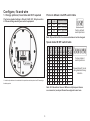
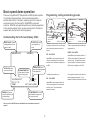
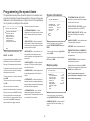
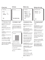
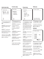
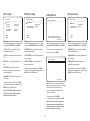
Concept Pro VHSD-810EXT Speed Dome System
User Manual
Rev 2.030V
Contents
Before installing
1
Key features
2
Configure, fix and wire
3
Basic speed dome operation
5
Programming the speed dome
6
Running selected features
12
Specifications
13
Installer notes
14
Before installing
!
- Installation should be carried out only by qualified personnel and in accordance with
any wiring regulations in force at the time.
- The speed dome is heavy and could cause injury if not correctly mounted in
accordance with these instructions. Use only the fittings supplied with the speed
dome and ensure that all lanyard safety cables are connected correctly during
installation.
- Adequate protection against lightning strikes and power surges must be installed to
prevent damage to the speed dome.
- Any safety warnings on the product and in these instructions must be adhered to.
- If cleaning is necessary, disconnect power to the speed dome first. Do not use
abrasive cleaners, as these will cause damage to the cover and cause poor image
quality. Use a damp cloth to gently clean the dome cover and dry off with a soft
clean cloth.
- Do not use any brackets, mounts or other accessories not specifically designed for
use with this speed dome.
- Do not attempt to service or repair the speed dome as opening or removing covers
may expose dangerous voltages or other hazards. Refer all servicing to qualified
service personnel.
1
Key features
Presets
Up to 127 sets of positional and zoom level information can be stored as
presets. These can be called manually by the operator, automatically by an
alarm input, or grouped to form a sequence of actions to run automatically.
Each preset supports titles of up to 10 characters and can also be
programmed to activate the alarm output. Additionally, White Balance and
Auto Exposure settings can be defined for each preset position if desired.
Privacy zones
By defining a privacy zone, sensitive scenes such as windows can be
masked off so they cannot be viewed by the operator. Up to 4 privacy
zones can be defined. Privacy zone size adjusts automatically depending
on the speed dome zoom level.
Alarm inputs and outputs
This speed dome has 2 alarm inputs and 1 alarm output. Any alarm input
can be set to call a predefined preset, VST function, pattern or group. Any
preset can be configured to activate the relay output. For example, a PIR
detector connected to alarm input 1 could call preset 7 to view that
particular scene whilst activating an external lamp connected to the relay.
Pattern tours
Any dome movement can be recorded - and subsequently played back - as
a pattern tour which can be played back individually or grouped to form a
sequence of tours. Up to 4 pattern tours of around 5 minutes each can be
defined.
On Screen Display (OSD)
The operator can choose if any or all of the following information is
displayed on screen during normal speed dome operation.
Variable Speed Tracking (VST) between 2 presets
A VST is a useful feature when, for example, the operator wishes to ‘patrol’
a perimeter fence. If one preset is defined at one end of the fence and a
second preset is defined at the other, the VST will smoothly and accurately
move from one end to the other and then back again in a repeating
sequence. Speed can be adjusted and up to 8 VST functions can be
defined.
- Preset status and title
- Speed dome position coordinates and zoom level
- Alarm I/O status
- Time and Date
- Speed dome ID
- Speed dome operating temperature
Group function
The group function is a powerful feature which allows the operator to define
a sequence of speed dome actions to form an automatic patrol sequence.
Actions can be a mix of preset positions, pattern tours and VST functions.
Up to 8 groups can be defined and each group can have up to 20 actions
which repeat indefinitely until interrupted by the operator or an alarm input.
Specific parameters such as preset speed, dwell time and action loop can
also be specified.
The speed dome also has a full on screen setup menu allowing quick and
easy configuration of all the speed dome features.
Scheduling function
The speed dome can be configured to run a specified VST function, pattern
tour, group or preset at a certain time either on a weekend, a specific day or
daily. Up to 8 scheduled actions can be defined.
Preset freeze
With preset freeze enabled, the speed dome image will freeze during a call
to preset in order to conserve DVR disk usage.
Park function
The speed dome can be configured to run a specified VST function, pattern
tour, group or preset after a defined period of inactivity.
2
Configure, fix and wire
Protocol & Baud rate DIP switch table
1. Change protocol, baud rate and ID if required
The factory default setting is Pelco D, 2400, ID 1. Skip to section
2 if these settings match your control equipment.
1
2
Protocol/Rate
OFF
ON
OFF
ON
OFF
OFF
ON
ON
Pelco D, 2400 bps
Pelco D, 9600 bps
Pelco P, 4800 bps
Pelco P, 9600 bps
ON
1
2
3
4
Factory default
switch positions
Note: Dip switches 3 & 4 are reserved and must not be changed.
Speed dome ID DIP switch table
1
DIP Switches
1. Locate the dip switches on the underside of the speed dome and set protocol and ID according to
the table opposite.
2
3
4
1
2
4
8
ON
OFF
ON
OFF
ON
OFF
ON
OFF
--ON
OFF
ON
ON
OFF
OFF
ON
ON
OFF
--ON
OFF
OFF
OFF
ON
ON
ON
ON
OFF
--ON
OFF
OFF
OFF
OFF
OFF
OFF
OFF
ON
--ON
5
6
7
8
OFF
OFF
OFF
OFF
OFF
OFF
OFF
OFF
--ON
OFF
OFF
OFF
OFF
OFF
OFF
OFF
OFF
--ON
OFF
OFF
OFF
OFF
OFF
OFF
OFF
OFF
--ON
OFF
OFF
OFF
OFF
OFF
OFF
OFF
OFF
--ON
DIP
1 6 3 2 6 4 1 2 8 Val I D
1
2
3
4
5
6
7
8
-
ON
1
2
3
4
5
6
8
Factory default
switch positions
Speed dome ID is set
using standard binary
notation
255
Note: ID 0 should not be used. Where multiple speed domes
are connected, a unique ID must be assigned to each one.
3
7
3. Verify basic operation
2. Fix the ceiling mount base
CONCEPT PRO SPEED DOME
-----------------------FIRMWARE VER : 2.030V
COLOUR SYSTEM : PAL
PROTOCOL
: PELCO-D
BAUD RATE
: 2400
ADDRESS
: 1
DATA MEMORY
: OK
ZOOM MODULE
: OK
HOME TEACHING.. OK
1. Drill a hole in the ceiling to pass the cables
through, and then fix the ceiling mount base
using suitable fixings.
2. Make cable connections to the speed dome
base for 12V DC power, video and RS-485
telemetry.
1. After carefully checking the installation and
all cable connections, apply power to the
speed dome and check that the startup and
self test screen is displayed.
07/JAN/2007
14:46:46
CAM 1
C
40
325/37/x1/NW
2. After the self test is complete, the speed
dome starts normal operation. Verify that there
is basic PTZ control from your control
equipment.
GND 12V
If there’s a problem at this stage...
External detector
volt free contacts
…work through the logical steps below to determine and rectify the problem
External
power
source
OUT
2
1
COM
Relay output max
125V AC @ 0.5A or
30V DC @ 1A
No picture - Check that the PSU is correctly connected and has power. If you have a test meter,
verify that the output of the PSU is 12V DC.
3. If required, connect alarm inputs and the
relay according to the above diagram. GND
and 12V can be taken from the speed dome
power supply.
If the PSU is OK, check the BNC crimp connection is correctly made at both the speed dome end
and the DVR / monitor / matrix end. A portable test monitor connected directly to the video output of
the speed dome is also a useful test - if a picture is displayed, double check the BNC connections
and the signal cable used.
4. Fix the main speed dome module to the
base using the four security screws.
No PTZ control - check that the control equipment you are using is compatible with the speed
dome and is configured to match the speed dome settings correctly.
If dip switches were changed on the speed dome, check the power on self test screen to ensure
that protocol, ID and baud rate are as expected.
If the settings match, you should check the polarity of the connections, both on the control
equipment and the speed dome. If you suspect there is a polarity issue, swap the A & B wires at the
speed dome to see if this resolves the problem.
Check also that there are no other telemetry devices on the system with the same ID as the speed
dome. If in doubt, connect the speed dome directly to the PTZ controller and isolate all other
equipment.
5. If using any optional brackets (wall mount, flush mount or pendant mount), the ceiling mount base
supplied with the speed dome is not required and should not be used.
4
Basic speed dome operation
Programming, calling and deleting presets
There are many different PTZ keyboards and DVR systems capable
of controlling this speed dome, and it would be impossible to
describe them all here. Therefore, examples given in this manual
are based on using the Concept Pro VA-KBDPRO+ keyboard
controller. Whilst the principles of operation are the same regardless
of the control equipment used, you may need to refer to the manual
supplied with your particular control equipment.
PARKING BAY 1
Understanding the On Screen Display (OSD)
PRESET LABEL: If defined,
is displayed when a preset
position is called
25/FEB/2007
14:46:46
CAM 1
ACTION TITLE: Shows
current speed dome
action
RECEPTION
C
40
325/37/x1/NW
To program a preset position, move the speed
dome to the desired scene and zoom level
and key:
PRESET3
SET - XXX - ENTER
Where XXX is a preset number between 1 &
128 (but note that preset 95 is reserved and
cannot be used). Confirmation is displayed on
the OSD.
DATE/CLOCK: Shows
current time and date
ALARM INFORMATION:
Shows status of the alarm
inputs and relay output
25/FEB/2007
09:37:15
CAM 1
CAMERA ID: Shows the
current ID as defined by the
dip switch settings
25/FEB/2007
14:46:53
CAM 1
PRESET3
C 40
325/37/x3/NW
To go to a preset position that’s already been
programmed, key:
PRESET - XXX - ENTER
Where XXX is a preset number between 1 &
128 (but note that preset 95 is reserved and
cannot be used). The speed dome moves to
the preset position. Confirmation and preset
title (if defined) is displayed on the OSD.
TEMPERATURE: Shows
current operating temperature
of the speed dome
To delete a preset position, key:
ESC - XXX - ENTER
C 40
I:-- O:307/46/x3/NW
Where XXX is a preset number between 1 &
128 (but note that preset 95 is reserved and
cannot be used). The preset position is
cleared from memory.
PTZ INFORMATION: The current
pan/tilt position in degrees and
the current zoom level
Note - any or all of the OSD items can be disabled in the speed dome setup menu if
required.
5
To re-programme a preset position, follow the
steps for programming a preset - it is not
necessary to delete the old preset position first.
Programming the speed dome
System information
The speed dome setup menu allows the operator to customise and
program all aspects of speed dome operation. All menu settings are
retained in non-volatile memory so if power is lost to the speed dome
for any reason, all settings will be retained.
The main menu has seven options:
CONCEPT PRO SPEED DOME
----------------------------<SYSTEM INFORMATION>
<DISPLAY SETUP>
<MOTION SETUP>
<FUNCTION SETUP>
<CAMERA SETUP>
<SYSTEM SETUP>
<SYSTEM INITIALISE>
EXIT
To access the speed dome setup menu, key:
PRESET - 95 - ENTER
If the password has been enabled, it must be
entered before the menu can be accessed.
See page 12 for password setup information.
To navigate the main menu, move the joystick
up / down to choose a menu item or change
settings within a menu item.
To enter a menu item or confirm a new setting,
key: NEAR
To exit a menu item or cancel a new setting,
key: FAR
Where a menu item is surrounded by
brackets, it indicates that there is a sub menu.
Where a menu screen shows EXIT, selecting
this option will exit the menu and the speed
dome will return to normal operation. Where a
menu screen shows BACK, selecting this
option will return to the higher menu level.
<SYSTEM INFORMATION> - Provides
information such as firmware version, protocol
and ID values as defined by the dip switch
settings.
S Y S T E M IN F O R M A T I O N
-----------------------------
PTZ INFORMATION (ON / OFF / AUTO) shows the current pan / tilt position in degrees
and the current zoom level.
FIRMWARE VER
C O L O U R SY S T E M
PROTOCOL
BAUD RATE
ADDRESS
ACTION TITLE (ON / OFF / AUTO) - shows
current speed dome action, eg PRESET3.
:
:
:
:
:
2.030V
PAL
PELCO-D
2400
1
BACK
EXIT
<DISPLAY SETUP> - Allows the operator to
specify which On Screen Display information
is shown during normal operation. Also allows
privacy zones to be defined.
From the main menu, use the joystick to
highlight SYSTEM INFORMATION and key:
NEAR
To return to the main menu, highlight BACK
and key: NEAR
<MOTION SETUP> - setup of the pan / tilt /
zoom operation of the speed dome, park
action configuration, and configuration of the
alarm inputs.
To exit the setup menu completely, highlight
EXIT and key: NEAR
<FUNCTION SETUP> - Allows configuration
of presets, VST functions, patterns, groups
and scheduled events.
Display setup
<CAMERA SETUP> - Allows configuration of
the operating parameters of the 10x zoom
module.
D I S P L A Y SE T U P
----------------------------CAMERA ID
ON
PTZ INFORMATION
AUTO
ACTION TITLE
AUTO
PRESET LABEL
AUTO
A L A R M I/ O
AUTO
DATE/TIME
ON
TEMPERATURE
CELSIUS
<PRIVACY ZONE>
BACK
EXIT
<SYSTEM SETUP> - Allows configuration of
time/date, fan/heater operating temperatures,
password setting, Home position configuration
and North direction configuration.
<SYSTEM INITIALISE> - Any or all of the
speed dome settings can be restored to
factory defaults. The speed dome can also be
re-booted with this menu option.
From the main menu, use the joystick to
highlight DISPLAY SETUP and key: NEAR
CAMERA ID (ON / OFF) - shows camera ID
according to the DIP switch settings, eg
CAM 1.
6
PRESET LABEL (ON / OFF / AUTO) - shows
preset label (if defined) when a preset is
called.
ALARM I/O (ON/OFF) - shows real time status
of the alarm inputs and outputs.
DATE/TIME - shows current date and time.
TEMPERATURE (CELSIUS / FAHRENHEIT /
OFF) - shows current operating temperature of
the speed dome.
<PRIVACY ZONE> - sub menu to setup the
speed dome privacy zones.
Highlight the item to modify and key: NEAR
Use the joystick to change the setting and key:
NEAR to save or: FAR to cancel.
Note: If the auto option is chosen, the
relevant information is displayed for a few
seconds before disappearing.
Edit zone
Privacy zone
PRIVACY ZONE
----------------------------ZONE NO.
1
DISPLAY
C L E A R ZO N E
< E D I T ZO N E >
Motion setup
EDIT ZONE 1
-----------------------------
M O T I O N SE T U P
----------------------------OFF
PRESET LOCK
ON
PWR UP ACTION
ON
AUTO FLIP
140/SEC
JOG MAX SPEED
INVERSE
JOG DIRECTION
OFF
FRZ IN PRESET
( P A R K I N G A C T I O N SE T U P )
(ALARM INPUT SETUP)
BACK
EXIT
OFF
CANCEL
BACK
EXIT
M O V E T O T A R G E T PO S I T I O N
[NEAR:SELECT/FAR:CANCEL]
From the display setup menu, use the joystick
to highlight PRIVACY ZONE and key: NEAR
From the privacy zone menu, use the joystick
to highlight EDIT ZONE and key: NEAR
From the main menu, use the joystick to
highlight MOTION SETUP and key: NEAR
ZONE NO. (1-4) - shows the privacy zone
currently being modified.
Use the joystick to move the speed dome to
the approximate position and zoom level for
the privacy zone and key: NEAR to select or
FAR to cancel and return to the privacy zone
menu.
PRESET LOCK (ON / OFF) - when set to ON,
preset programming from the keyboard is
disabled.
DISPLAY (ON / OFF) - determines whether
the privacy zone is displayed during normal
operation.
CLEAR ZONE - option to delete the currently
selected privacy zone.
PWR UP ACTION (ON/OFF) - when set to
ON, the last operation is resumed when power
is restored after a power failure.
AUTO FLIP (ON / OFF) - when set to ON, the
dome will flip when tilt reaches 90 degrees.
EDIT ZONE 1
-----------------------------
<EDIT ZONE> - allows the operator to define
the privacy zone.
Highlight ZONE NO and key: NEAR. Move the
joystick up and down to select the privacy
zone number to change and key: NEAR
Highlight the item to modify and key: NEAR
Use the joystick to change the setting and key:
NEAR to save or: FAR to cancel.
[
[
: A D J U S T ZO N E W I D T H ]
: A D J U S T ZO N E H E I G H T ]
[NEAR:SAVE
/FAR:CANCEL]
Move the joystick left and right to finely adjust
the width of the privacy zone and up and down
to finely adjust the height.
BACK
EXIT
From the motion setup menu, use the joystick
to highlight PARKING ACTION SETUP and
key: NEAR
PARK ENABLE (ON/OFF) - when set to ON,
the speed dome will run the specified park
action after the wait time has elapsed.
WAIT TIME - can be set between one second
and 4 hours. If no manual control occurs
during this time, the park action will run.
PARK ACTION - choose the action to run after
the wait time has elapsed. This can be return
to home position or any preset, VST function,
group or pattern tour.
JOG DIRECTION (INVERSE / NORMAL) when set to normal, the pan direction is
opposite to the joystick movement.
Highlight the item to modify and key: NEAR
Use the joystick to change the setting and key:
NEAR to save or: FAR to cancel.
FRZ IN PRESET (ON / OFF) - when set to ON
the image is frozen during preset movements.
Note: if the speed dome is running a
pattern tour, VST function or group
function, the parking action will not run.
<ALARM INPUT SETUP> - Configure the
action of the alarm inputs.
Highlight the item to modify and key: NEAR
Use the joystick to change the setting and key:
NEAR to save or: FAR to cancel.
7
PARKING ACTION SETUP
----------------------------OFF
PARK ENABLE
00:10:00
WAIT TIME
HOME
PARK ACTION
JOG MAX SPEED - the maximum speed in
degrees / second during manual operation.
<PARKING ACTION SETUP> - Configure an
action that runs after a defined period of
inactivity.
To save the privacy zone, key: NEAR or key:
FAR to cancel.
Parking action setup
Alarm input setup
ALARM INPUT SETUP
----------------------------N.OPEN
ALARM 1 TYPE
N.OPEN
ALARM 2 TYPE
NOT USED
ALARM 1 ACT
NOT USED
ALARM 1 ACT
BACK
EXIT
From the motion setup menu, use the joystick
to highlight ALARM INPUT SETUP and key:
NEAR
ALARM 1,2 TYPE - each alarm input can be
configured as Normally Open or Normally
Closed.
ALARM 1,2 ACT - for each alarm action,
specify the preset number, VST function,
pattern tour or group to call. Leave set to NOT
USED to disable the alarm input.
Highlight the item to modify and key: NEAR
Use the joystick to change the setting and key:
NEAR to save or: FAR to cancel.
Function setup
Preset setup
FUNCTION SETUP
----------------------------<PRESET SETUP>
<VST SETUP>
<PATTERN SETUP>
<GROUP SETUP>
<SCHEDULE SETUP>
PRESET SETUP
----------------------------PRESET NO.
1
Edit scene
EDIT SCENE - PRESET 1
-----------------------------
< E D I T SC E N E >
< E D I T LA B E L >
CLR PRESET
CANCEL
CAM ADJUST
GENERAL
A L A R M OU T
OFF
BACK
EXIT
BACK
EXIT
M O V E T O T A R G E T PO S I T I O N
[NEAR:SAVE /FAR:CANCEL]
From the main menu, use the joystick to
highlight FUNCTION SETUP and key: NEAR
From the function setup menu, use the joystick
to highlight PRESET SETUP and key: NEAR
From the preset setup menu, use the joystick
to highlight EDIT SCENE and key: NEAR
<PRESET SETUP> - full management and
programming of individual presets.
PRESET NUMBER (1 - 128) - The preset
number currently being modified. If the preset
number is already defined, the speed dome
will move to that preset position, otherwise
UNDEFINED is displayed under the preset
number.
Using the joystick, move the speed dome to
the desired position and zoom level and key:
NEAR to save or: FAR to cancel.
<VST SETUP> - full management and
programming of preset to preset VST
functions.
<PATTERN SETUP> - full management and
programming of pattern tours.
<EDIT SCENE> - use this option to program
the preset position.
<GROUP SETUP> - full management and
programming of group functions.
<EDIT LABEL> - use to edit the preset label.
CLR PRESET - use this option to delete the
current preset position.
<SCHEDULE SETUP> - full management and
programming of scheduled actions.
CAM ADJUST - Can be changed to SPECIAL
which allows white balance and auto exposure
to configured for each preset position. See
page 11 & 12 for white balance and auto
exposure programming details.
Highlight the setup menu required and key:
NEAR
Remember: A menu item surrounded by
brackets shows it has a sub menu.
ALARM OUT - set to ON to activate the relay
output when this preset position is called.
8
Edit label
EDIT LABEL - PRESET 1
----------------------------[
]
---------1234567890
OK
ABCDEFGHIJ
CANCEL
KLMNOPQRST
UVWXYZabcd
efghijklmn
opqrstuvwx
yz<>-/:.
Backspace
Space
From the preset setup menu, use the joystick
to highlight EDIT LABEL and key: NEAR
Move the joystick to choose the required
character and key: NEAR to insert it. Repeat
until the preset label is complete.
The last 4 options above are only available
when the selected preset position has been
programmed.
If a mistake is made, select and key: NEAR.
The cursor moves back one square.
Highlight the item to modify and key: NEAR
Use the joystick to change the setting and key:
NEAR to save or: FAR to cancel.
Select OK to save the preset label or
CANCEL to lose changes, and key: NEAR to
exit.
VST setup
Pattern setup
VST SETUP
----------------------------1
VST NO.
NOT USED
1ST POS.
NOT USED
2ND POS.
VST SPEED
C L E A R VS T
Group setup
Edit pattern
P A T T E R N SE T U P
----------------------------PATTERN NO.
1
UNDEFINED
CLR PATTERN
CANCEL
< E D I T PA T T E R N >
EDIT PATTERN 1
-----------------------------
GROUP SETUP
----------------------------1
G R O U P NO .
UNDEFINED
CANCEL
C L E A R GR O U P
< E D I T GR O U P >
30/SEC
CANCEL
BACK
EXIT
BACK
EXIT
MOVE TO START POSITION
[NEAR:START /FAR:CANCEL
BACK
EXIT
0/0/x1/N
From the function setup menu, use the joystick
to highlight VST SETUP and key: NEAR
From the function setup menu, use the joystick
to highlight PATTERN SETUP and key: NEAR
From the pattern setup menu, use the joystick
to highlight EDIT PATTERN and key: NEAR
From the function setup menu, use the joystick
to highlight GROUP SETUP and key: NEAR
VST NO. (1-8) - shows the VST number
currently being modified.
PATTERN NO. (1 - 4) - The pattern number
currently being modified.
Position the speed dome to the desired
starting point and key: NEAR
GROUP NO. (1-8) - shows the group number
currently being modified.
1ST POS. - any defined preset between 1 &
128.
CLR PATTERN - the currently selected pattern
can be deleted.
CLEAR GROUP - the currently selected group
can be deleted.
EDIT PATTERN 1
2ND POS. - any defined preset between 1 &
128.
<EDIT PATTERN> - allows the operator to
program a pattern tour
<EDIT GROUP> - allows the operator to
program the group functions.
VST SPEED - determines the speed of
movement in degrees per second between
each preset position.
Highlight the item to modify and key: NEAR
Use the joystick to change the setting and key:
NEAR to save or: FAR to cancel.
Highlight the item to modify and key: NEAR
Use the joystick to change the setting and key:
NEAR to save or: FAR to cancel.
CLEAR VST - deletes the currently selected
VST function.
0/0/x1/N
Highlight the item to modify and key: NEAR
Use the joystick to change the setting and key:
NEAR to save or: FAR to cancel.
Move the dome to the various positions and
zoom levels required for the pattern. The white
squares at the top of the display show
remaining storage and disappear as the
pattern is recorded.
Note: A VST function always moves anticlockwise to the 1st position and then
clockwise to the 2nd position.
To save the pattern, key: NEAR
To abandon pattern programming, key: FAR
Note: Pattern tour memory is only used
when movements are recorded. Pauses
between movements, regardless of time,
do not use pattern tour memory.
9
Edit group
EDIT GROUP
1
----------------------------N O A C T I O N ## # D W E L L O P T
----------------------------1 NONE
2 NONE
3 NONE
4 NONE
5 NONE
----------------------------SAVE
CANCEL
[NEAR:EDIT]
Schedule setup
Edit group
EDIT GROUP 1
----------------------------N O A C T I O N ## # D W E L L O P T
----------------------------1 PATTERN 1 00:03
1
2 PRESET
5 00:08 360
3 VST
3 00:03
8
4 PRESET 10 00:15 110
5 PRESET
4 01:30
55
----------------------------SAVE
CANCEL
[NEAR:EDIT]
SCHEDULE SETUP
----------------------------OFF
MASTER ENABLE
DAY TIME ACT No
1 UNDEFINED
2 UNDEFINED
3 UNDEFINED
4 UNDEFINED
5 UNDEFINED
6 UNDEFINED
7 UNDEFINED
8 UNDEFINED
BACK
From the group setup menu, use the joystick
to highlight EDIT GROUP and key: NEAR
Key NEAR to save this item and continue
adding more items as necessary.
To edit the group, key: NEAR again
From the function setup menu, use the joystick
to highlight SCHEDULE SETUP and key:
NEAR
Once all group actions are defined, key: FAR
and then select SAVE to save the group and
return to the group setup menu, or CANCEL
to discard all changes.
Schedule setup allows the operator to define
up to 8 schedules to perform a speed dome
operation at a specific time and day.
Header explanation:
NO - the item number (between 1 & 20).
ACTION - the specific action for this item
### - the action number (eg if ACTION is set
to PRESET, this value can be between 1 &
128.
DWELL - the amount of time before the next
action in the list is called.
OPT - for PRESET actions, this value is the
speed at which the dome moves to the preset.
For VST and PATTERN, this value is the
number of times the action is repeated before
the next action is called.
Note - ensure that the correct time and date
is set on the speed dome before using
schedules.
MASTER ENABLE (ON/OFF) - switches all
schedule operations ON or OFF.
Schedule header explanation:
DAY - Can be set to ALL for every day of the
week, a specific day or WKD for weekends
only.
Move the joystick up and down to choose the
group item to modify and key: NEAR. The
ACTION is highlighted in white.
TIME - Uses the 24 hour clock format to set
the desired operation time.
Move the joystick up and down to change the
action type between NONE, PRESET, VST
and PATTERN.
ACT - is the action to be performed and can
be set to PRS (preset), VST, PTN (pattern),
GRP (group) or HOM (home).
Move the joystick left and right to select and
edit values for ###, DWELL & OPT.
No - is the number of the chosen action (eg
operator could select 67 to go to Preset 67).
Move the joystick up and down to choose the
schedule to modify and key: NEAR.
UNDEFINED flashes
10
Schedule setup
SCHEDULE SETUP
----------------------------ON
MASTER ENABLE
DAY TIME ACT No
1 TUE 14:25 PRS 18 ON
2 ALL 09:00 VST 7 ON
3 UNDEFINED
4 UNDEFINED
5 UNDEFINED
6 UNDEFINED
7 UNDEFINED
8 UNDEFINED
BACK
Move the joystick up and down to change the
day for the scheduled action.
Move the joystick right so that the hours value
flashes, and move the joystick up and down to
change.
Continue as above to select the desired
minutes, action & action number and ensure
that ON is selected to enable the schedule.
The above example shows that Preset 18 will
be called every Tuesday at 14:25 and VST
function 7 will run every day at 09:00.
Once the schedule is defined, key: NEAR to
save.
Repeat the above to define up to 8 schedule
operations in total. Ensure that MASTER
ENABLE is set to ON to enable all schedules.
Note that if scheduled operations clash,
the higher number schedule takes priority.
Note that preset action numbers can be
used to call special functions in a
schedule. For example, a schedule can be
programmed to call preset 194 at a
particular time to switch all privacy zones
on - see page 13, Running selected
features, for more information.
Camera setup
Z O O M C A M E R A SE T U P
----------------------------F O C U S MO D E
SEMIAUTO
DIGITAL ZOOM
ON
I M A G E FL I P
ON
< W H I T E B A L A N C E SE T U P >
< A U T O EX P O S U R E SE T U P >
BACK
EXIT
From the main menu, use the joystick to
highlight CAMERA SETUP and key: NEAR
FOCUS MODE
MANUAL - the operator must focus the
camera manually using the NEAR and FAR
keys.
SEMIAUTO - the camera automatically
focuses during normal PTZ movement but
preset focus information is stored when a
preset is programmed and recalled each time
the preset is called.
AUTO - the module auto focuses continually.
DIGITAL ZOOM (ON / OFF) - disables or
enables the 10x digital zoom. When disabled,
the maximum zoom level is 10x (optical).
IMAGE FLIP (ON / OFF) - should be set to
OFF when the speed dome is mounted
conventionally. When set to ON, the image is
rotated by 180 degrees and is required if the
speed dome is mounted on top of a vehicle,
for example.
White balance setup
Auto exposure setup
WB SETUP
----------------------------WB MODE
AUTO
RED ADJUST
--B L U E AD J U S T
---
AE SETUP
----------------------------BACKLIGHT
OFF
DAY/NIGHT
AUTO1
BRIGHTNESS
25
IRIS
AUTO
SHUTTER
ESC
AGC
NORMAL
SSNR
MIDDLE
DSS
<AUTO>
BACK
EXIT
BACK
EXIT
From the zoom camera setup menu, use the
joystick to highlight WHITE BALANCE SETUP
and key: NEAR
From the zoom camera setup menu, use the
joystick to highlight AUTO EXPOSURE
SETUP and key: NEAR
WB MODE (AUTO / MANUAL)
AUTO - the speed dome determines the
optimum white balance settings for a given
scene.
MANUAL - the operator can adjust white
balance settings manually.
BACKLIGHT (ON/OFF) - switches backlight
compensation ON or OFF.
DAY/NIGHT (AUTO1/AUTO2/DAY/NIGHT) the operator can choose to fix the camera in to
DAY (colour) or NIGHT (B&W with IR cut filter)
mode. In AUTO1 & AUTO2 mode, the camera
switches between DAY and NIGHT depending
on the surrounding light level. In AUTO2
mode, the change from NIGHT to DAY
happens at a lower light level.
RED ADJUST - in manual mode, the red
colour content can be adjusted.
BLUE ADJUST - in manual mode, the blue
colour content can be adjusted.
BRIGHTNESS - the overall image brightness
can be adjusted.
Highlight the item to modify and key: NEAR
Use the joystick to change the setting and key:
NEAR to save or: FAR to cancel.
IRIS (AUTO / MANUAL) - the iris will adjust
automatically depending on the scene’s light
level. When set to MANUAL, the iris can be
set manually.
SHUTTER (ESC / A.FLICKER / MANUAL)- in
ESC mode, the shutter automatically adjusts
to a light levels in the scene. A.Flicker
provides better shutter control to handle
internal fluorescent lighting. MANUAL allows
the shutter to be set manually.
<WHITE BALANCE SETUP> - sub menu to
change the white balance settings.
<AUTO EXPOSURE SETUP> - sub menu to
change the auto exposure settings.
11
AGC(NORMAL / HIGH / OFF) - AGC adjusts
the camera output signal so that it is constant
regardless of lighting conditions.
SSNR (OFF / LOW / MIDDLE / HIGH) - the
sensitivity of the digital noise reduction system
can be adjusted to suit particular viewing
conditions.
DSS (AUTO / OFF) - digital slow shutter. The
camera will stop the shutter digitally to
enhance images in poor lighting conditions.
When set to AUTO, the maximum DSS limit
can be set by the operator.
System setup
SYSTEM SETUP
----------------------------C40
FAN RUN TEMP
C5
HEATER RUN TEMP
DATE
25/FEB/2008(MON)
TIME
14:37:15(H/M/S)
OFF
C H E C K PA S S W O R D
< E D I T PA S S W O R D >
<SET HOME POSITION>
<SET NORTH DIRECTION>
BACK
EXIT
EDIT PASSWORD
----------------------------[
]
---------1234567890
OK
ABCDEFGHIJ
CANCEL
KLMNOPQRST
UVWXYZabcd
efghijklmn
opqrstuvwx
yz<>-/:.
Backspace
Space
From the main menu, use the joystick to
highlight SYSTEM SETUP and key: NEAR
From the system setup menu, use the joystick
to highlight EDIT PASSWORD and key: NEAR
FAN RUN TEMP - The temperature at which
the internal fan starts.
The solid white square shows the current
cursor position.
This flashing white square shows the currently
selected character.
HEATER RUN TEMP - The temperature at
which the internal heater starts.
DATE - current date.
TIME - current time.
CHECK PASSWORD (ON / OFF) - When set
to ON, the operator must enter a password to
access the setup menu.
<EDIT PASSWORD> - sub menu to change
the password.
<SET HOME POSITION> - sub menu to
change the home position.
<SET NORTH DIRECTION> - sub menu to
change the North direction.
Highlight the item to modify and key: NEAR
Move the joystick up and down to change an
individual value and left and right to move to
the previous / next value.
Set home position
Edit password
Move the joystick up / down / left / right to
choose the required character and key: NEAR
to insert it in the password. The solid white
square moves to the next cursor position.
Repeat until password entry is complete.
SET HOME POSITIION
-----------------------------
SET NORTH DIRECTION
-----------------------------
M O V E T O T A R G E T PO S I T I O N
[NEAR:SELECT/FAR:CANCEL]
0/0/x1/N
M O V E T O T A R G E T PO S I T I O N
[NEAR:SELECT/FAR:CANCEL]
The default home position is at 0 degrees. To
change it, use the joystick to highlight SET
HOME POSITION and key: NEAR
The default North direction is at 0 degrees. To
change it, use the joystick to highlight SET
NORTH DIRECTION and key: NEAR
Use the joystick to move the speed dome to
the new home position and key: NEAR to
select or FAR to cancel and return to the
display menu.
Use the joystick to move the speed dome to
the new North direction and key: NEAR to
select or FAR to cancel and return to the
display menu.
Note: the home position defines the origin
for all presets, VTS functions and pattern
tours. If, for example, the home position is
changed to 30/0/x1/N, then all speed dome
functions will be shifted to the right by 30
degrees. If the home position is
accidentally changed, it can be reset by
selecting CLR MOTION SET in the system
initialise menu (see page 13).
If a mistake is made, use the joystick to select
the backspace ( ) and key: NEAR. The cursor
moves back one square.
Select OK to save the password or CANCEL
to lose changes and key: NEAR to exit.
Remember: When CHECK PASSWORD is
set to ON, each time the operator attempts
to enter the speed dome setup menu, the
above screen will be displayed. The correct
password must be entered to continue with
menu setup.
Note: the default temperature values
provide optimum protection in extreme
conditions. Changing these values could
cause damage to the speed dome.
12
Set North Direction
System initialise
S Y S T E M IN I T I A L I S E
----------------------------C L E A R AL L D A T A
NO
CLR DISPLAY SET NO
C L R C A M E R A SE T
NO
C L R M O T I O N SE T
NO
CLR FUNCTION SET NO
REBOOT CAMERA
NO
REBOOT SYSTEM
NO
BACK
EXIT
Running selected features Installer notes
Once pattern tours, groups and VST functions
have been programmed in the speed dome
setup menu, they can be accessed directly
from the VA-KBDPRO+ by using the following
sequences.
1. To start a pattern tour, key either:
X - PATTERN *or* PRESET - 13X - ENTER
Where X is a pattern tour between 1 & 4.
2. To start a VST function, key either:
X - VST *or* PRESET - 14X - ENTER
From the main menu, use the joystick to
highlight SYSTEM INITIALISE and key: NEAR
CLEAR ALL DATA - selecting this option will
perform a full factory reset on the speed
dome. CAUTION: this option will erase all
speed dome functions (patterns, presets etc.)
CLR DISPLAY SET - this option will reset the
on screen display settings to factory default
and erase all privacy zones.
CLR CAMERA SET - this option will reset the
camera module settings to factory default.
CLR MOTION SET - this option will reset the
motion menu settings to factory default and
erase all schedules.
CLR FUNCTION SET - this option will erase
all presets, VST functions, patterns, groups.
REBOOT CAMERA - this option will reboot
the camera module only.
REBOOT SYSTEM - this option will reboot the
entire speed dome system.
Highlight the item to modify and key: NEAR
Use the joystick to change the setting to YES
and key: NEAR to confirm or: FAR to cancel.
Where X is a VST number between 1 & 8.
3. To start a group, key:
X - GROUP *or* PRESET - 15X - ENTER
Where X is a group number between 1 & 8.
The selected functions will run indefinitely
until a manual movement is made by the
operator, an alarm input is received, or a
scheduled operation occurs.
4. Additional functions
Special features of the speed dome can be
called directly by using the following
sequences
Activate relay: SET - 161 - ENTER
Deactivate relay: PRESET - 161 - ENTER
Force DAY mode: PRESET - 179 - ENTER
Force NIGHT mode: PRESET - 178 - ENTER
Force AUTO mode: PRESET - 177 - ENTER
Switch OSD to auto: PRESET - 190 - ENTER
Switch OSD off: PRESET - 191 - ENTER
Switch OSD on: PRESET - 192 - ENTER
Privacy zones on: PRESET - 194 - ENTER
Privacy zones off: PRESET - 193 - ENTER
Note: the special features above can be
called by schedules so it is possible, for
example, to define the exact time of day for
DAY / NIGHT switching.
13
This page is left blank for any notes which may be useful once installation is complete.
Specifications
Camera
Pan / Tilt
CCD
¼” Day / Night
Resolution
500TVL (colour), 570TVL (B&W)
Minimum Illumination
0.7 Lux (colour), 0.02 Lux (B&W)
Optical Zoom
10x f=3.8 ~ 38mm (F1.8)
Digital Zoom
10x (total zoom 100x with optical zoom)
S/N Ratio
50db (AGC Off)
Focus
Auto / Semiauto / Manual
White Balance
Auto, Manual (Red and Blue adjust)
Back Light Compensation
On / Off
General
Pan: 360 degrees continuous rotation
Speeds
Manual / pattern tour: 0.1 - 180 degrees / second
Tilt: 180 degrees with auto picture flip function
Preset to preset: 360 degrees / second
Scan: 1 - 180 degrees / second adjustable in 1 degree steps
Preset positions
Communication
Mechanical
Up to 127, 10 character title per preset
Pattern tours
Up to 4
VST function
Up to 8, speed adjustable
Groups
Up to 8, each with up to 20 actions (preset, pattern tour or VST function)
Privacy zones
Up to 4, user definable
Schedules
Up to 8, user definable
Park function
Park to specified preset, pattern or scan after a defined period of inactivity (1 min ~ 4 hours)
Data type
RS-485
Protocols
Pelco-D or Pelco-P
Baud rates
2400, 4800, 9600
Camera ID
1-255
Alarm I/O
2 inputs, 1 relay output (max 125V AC 0.5A, 30V DC 1A)
On Screen Display
OSD menu, camera position, dome ID, alarm status, preset / scan / pattern tour status, temp
Fan / Heater
Built in, programmable operating thresholds
Operating temperature range
0 deg C to 40 deg C
Humidity
<95%
Power supply
12V DC, 800ma
Dimensions
147.5mm (dia) x 141mm (H)
Weight
1.2Kg
14