1
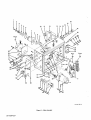
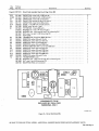
OM-1038
FORM:
September 1975
Effective with Serial No.
HF875171
MODEL
STOCK NO.
CONTROL/FEEDER
MILLERMATIC 70A
.030 WIRE
057 361
.035 WIRE
057 367
.045 WIRE
057 368
MILLERMATIC 80A
MODEL/STOCK NO.
SERIAL/STYLE NO.
OWNERS
.030 WIRE
058 000
.035 WIRE
058 001
.045 WIRE
058 002
DATE PURCHASED
MANUAL
MILLER ELECTRIC MFG. CO.
APPLETON, WISCONSIN, USA 54911
ADDITIONAL COPY
PRICE 35 CENTS
to
NWSA CODE NO. 4579
I,. 5.5.
4
)
4
4
I
H
C
c
C)
4
~
I
C
C
4
Mfg. Co.s obligation, under this warranty, is limited to replacing or repairing any defective
part or correcting any manufacturing defect without charge during the warranty period if MILLERS inspection confirms the existence of such defects. MILLERS option of repair or replacement will be f.o.b. factory at
Appleton, Wisconsin or f.o.b. a MILLER authorized service facility, and therefore no compensation for trans
portation costs of any kind will be allowed.
4
C
C
)
C
)
~
C
C)
c
C)
C
I
~
The warranty
C
~
C)
MILLER Electric
C
~
is installed and
C
4
,
to be free from defects in
new equipment
Mfg. Co., Appleton, Wisconsin,
factory workmanship for the periods indicated below, provided the equipment
operated according to manufacturers instructions.
warrants all
material and
C
~
C
H
WARRANTY
MILLER Electric
C
c
period, beginning
on
the date of sale to the
original purchaser-user
of the
equipment,
will be
as
I
I
follows:
1.
2.
3.
Arc
CD
CD
welders,
power sources, and components
main power rectifiers
MHFC-L1 Feeder, MHG-35C1, 20E, 20K,
1 year
3 years
and all guns and torches
All other Millermatic Feeders
90 days
Original
4.
5.
DEL-200
(unconditionally)
C
C
1 year
6 months
6.
C)
C)
9
6
)
D
to
trade
CD
C)
C)
~
MILLER Electric
~
directly
or
Co. will not be liable for any loss or consequential
from the use of equipment covered in this warranty.
Mfg.
indirectly
damage
or
expense
accruing
C)
c
C)
C)
~
3
c
~
C)
C)
C
handled
C)
C
I
3
Mag-Diesel engine
All other engines
1 year
Engine Warranties are covered by the engine manufacturers, subject to their procedures and to be
through their authorized local Service Stations or agencies. No warranty will be made in respect
accessories, such being subject to the warranties of their respective manufacturers.
on
-)
CD
This warranty supersedes all previous MILLER warranties and is exclusive with
warranties expressed or implied.
no
other guarantees
or
C
9
C)
c
C)
9
C)
Q Q Q Q O Q~Q~~PP QQQ Q Q~~Q
p
OJ
Q
~OrOOTrOO~ObdooObOObThO~oo~Ob
dThT~
Turntable Assembly (Stock No. 057 522)
Rotates
as
the operator
changes
work
positions. Eliminates cable strain and reduces wire feed friction.
Quick Disconnects (Stock No. 057 459)
Permits
rapid
connection and disconnection of
welding cables.
TABLE OF CONTENTS
Paragraph No.
SECTION 1
1
1
1
-
-
-
Page
INTRODUCTION
1.
General
1
2.
Receiving-Handling
1
3,
Description
Safety
1
1-4.
SECTION 2
INSTALLATION
2-1.
Location
2- 2.
Swivel
2- 3.
115 Volts AC Connections
2
2
4.
Contactor Control Connections
2
5.
Shielding Gas
2
6.
Switch Control Connections
2
7.
Weld Cable Terminal And Access Hole
2
2
2
2
-
-
-
-
1
Carrying
Handle (80A Models
Only)
1
Connections
2- 8. Wire Guide And Drive Roll Gear Installation
2
9.
2
Spool Type Welding Wire Installation (70A Models Only)
2-10. Four Inch Spool Type Welding Wire Installation (70A Models Only)
2-11. Installation Of Welding Wire Eight Inch And Twelve Inch Spool (BOA Only)
2-12. Hub Tension Adjustment
3
2-13.
Strain Relief Installation
4
2-14.
Welding Wire Threading
4
-
Eight
Inch
.
.
..
SECTION 3
3
-
3
-
-
-
4
-
-
4
Speed Control
3. Purge Button
5
4.
Inch Switch
5
6.
Pilot Lamp (8OA Models
5
1.
2.
-
1.
5
Only)
5
SEQUENCE OF OPERATION
Gas Metal-Arc Welding (GMAW)
Shutting Down
SECTION 5
5
3
Power Switch
SECTION 4
4
3
FUNCTION OF CONTROLS
3-5. Circuit Breaker
3
3
Wire
1.
3- 2.
3
-
5
5
MAINTENANCE
Inspection and Upkeep
SECTION 6
PARTS LIST
TROUBLESHOOTING
6
No.
SECTION 1
-
INTRODUCTION
Weight
Model
Electrode Wire
Electrode Wire
Dia. Capability
Feed Speed
Control Circuit
Power
at
(Pounds)
Dimensions
(Inches)
Gun
Net
Ship
27
34
Height- 13-1/4
70A
Width
50-675
24 Volts
ipm
AC
.030.045
Depth
Width
Depth
1-1.
13-1/4
-
-
45.5
51
22-1/4
1-1. Specifications
GENERAL
~~uIi.i~JuiiJ
This manual has been prepared especially for use in familiar
izing personnel with the design, installation, operation, main
tenance, and troubleshooting of this equipment. All informa
I
Under
this
heading, installation, operating, and main
procedures or practices will be found that if
not carefully followed may create a safety hazard to
personnel
tion presented herein should be given careful consideration to
assure optimum performance of this equipment.
1-2.
18
-
Height- 17-1/2
80A
Figure
11
-
I
tenance
-
I
RECEIVING-HANDLING
I
Prior
to installing this equipment, clean all packing material
from around the unit and carefully inspect for any damage
that may have occurred during shipment. Any claims for loss
~~TAN~
damage that may have occurred in transit must be filed by
the purchaser with the carrier. A copy of the bill of lading
and freight bill will be furnished by the carrier on request if
occasion to file claim arises.
or
Under
this
heading, installation, operating, and main
procedures or practices will be found that if
carefully followed may result in damage to equip
tenance
When requesting information concerning this equipment, it is
essential that Model Description and/or Stock Number and
Serial (or Style) Numbers of the equipment be supplied.
1-3.
not
ment.
I
I
DESCRIPTION
This control/feeder is of the constant wire feed
is designed to be used in conjunction with
and
potential welding power
speed type
a
constant
source.
I
1-4.
I
SAFETY
Under this heading, explanatory statements will be
found that need special emphasis to obtain the most
efficient operation of the equipment.
The
following definitions apply to CAUTION, IMPORTANT,
and NOTE blocks found throughout this manual:
SECTION 2
2- 1. LOCATION
-
INSTALLATION
to
(Figure 2-1)
the portability of this unit, the unit may be located wher
desired. Suitable space should be allowed for making
ever
necessary Connections.
2
-
2. SWIVEL CARRYING HANDLE (80A Models
Only)
(Figure 2-2)
Handle In Normal Position For
Carrying By One Person
Figure 2-1. Control/Feeder
Dimensions
Refer to Figure 2-1 for dimensional information on the
control/feeder. Lead lengths must be considered when install
ing the control/feeder. If the welding power source can be
located near the work area, the control/feeder can usually be
installed on top of the welding power source. However, due
TB-058 000-2
Figure 2-2. 80A
Model
Carrying Handle
OM-1038 Page 1
The carrying handle
facilitate two-person
on
the 80A model
carrying.
Figure
may be rotated to
illustrates this
2-5. SHIELDING
(Figures
GAS CONNECTIONS
2-4 &
3-1)
2-2
usage.
Determine
2
-
3. 115 VOLTS AC
CONNECtIONS (Figures
Attach
one end of the 115 volts power cable to the
supplied
prong female plug as shown in Figure 2-3. It is recom
mended that a 16/3 conductor cable be used as the 115 volts
power cable. After attachment of the 115 volts plug to the
3
The shielding gas hose which comes from the gun is to be
attached to the output shielding gas connector, labeled GAS,
on the front panel of the control/feeder. Refer to Figure 3-1
for gas output connections. This connector has right-hand
115 volts power cable is complete, insert the 115 volts
plug
into the 115 VOLTS AC Receptacle on the rear panel
of the control/feeder and rotate the 115 volts plug as far as it
will turn in a clockwise direction. This rotating action will
lock the plug in the receptacle and prevent the plug from
fully
pulling
should tension be applied to the 115 volts power
cable. Connect the remaining end of the 115 volts power
cable to a 115 volts ac 60 Hertz power supply.
threading.
out
(Green Hex-Head
2-6. SWITCH CONTROL CONNECTIONS
two-pole twistlock receptacle is provided on the front
panel of the control/feeder for making switch control con
nections. When the switch connected across this receptacle is
closed, the contactor in the welding power source will
energize, shielding gas will flow, and wire will begin to feed.
screwr7~
~ ~eTerm
4. CONTACTOR
CABLE TERMINAL
2-4 & 3-1)
terminal
weld cable to the weld cable terminal, Insert the
weld cable from the gun through the access hole in the front
of the control/ feeder and connect the weld cable to the weld
cable terminal. Refer to Figures 2-4 and 3-1, respectively, for
rear
Plug Installation
CONTROL CONNECTIONS
and front weld cable
one end of the contactor control cable to the supplied
2 prong male plug. It is recommended that a 16/2 conductor
cable be used for the contactor control cable. After attach
ment of the contactor control plug to the contactor control
cable is complete, insert the contactor control plug fully into
the Contactor Control Receptacle on the rear panel of the
control/feeder and rotate the contactor control plug as far as
it will turn in a clockwise direction. This rotating action will
lock the plug in the receptacle and prevent the plug from
the
should tension be applied to the contactor
out
cable. Attach the remaining end of the contactor
cable to the contactor control connection point on
welding power
source.
70A Model
Page
holes.
Ensure that the weld cable terminal is kept clean at all
Also ensure that the nut on this terminal is
If either one of the above conditions is not
secure.
times.
met, erratic weld
current
could result.
2-8. WIRE GUIDE & DRIVE
LATION (Figure 2-5)
Upon
initial installation,
ROLL
GEAR
INSTAL
as a result of wire size changes, it
required drive rolls and wire guides
particular wire size. Having selected the
related parts, proceed to the following
or
is necessary to install the
accommodate the
desired wire size and
installation instructions:
to
TB-004 526
80A Model
Figure 2-4. Rear Panel Views
2
access
ETANr1
(Figure
Attach
pulling
is
connect the
2-4)
control
control
AND ACCESS HOLE
provided behind the left access door of the
to serve as a junction point for joining to
gether the weld cables from the welding power source and
the gun. Insert the weld cable from the welding power source
through the access hole in the rear of the control/ feeder and
A
TA-056 17g-1s
-
7. WELD
control/feeder
(Gold & Silver Round Screws)
Volts AC
.
(Figures
i nals
Figure 2-3. 115
(Figure 3-1)
A
2
2
the distance the control/feeder is to be located
welding power source and then connect a hose from
the shielding gas regulator-flowmeter on the shielding gas
supply to the gas input connection on the rear of the con
trol/feeder. Refer to Figure 2-4 for gas input connections.
This connection has a right-hand thread.
from the
2-3 & 2-4)
TB-004 452
1.
Loosen
adjustment wing
pressure
nut
2-5) and pull downward. Lift gear
in an upright position.
2.
3.
cover
(item 11, Figure
(2) up until it is
Using a 1/8 inch allen wrench, remove shoulder
and then pull Out drive roll gear (1).
Insert replacement drive roll gear (1) into gear
place with shoulder screw (3).
screw
(3)
Remove nylon hex-nut
4.
cover
(2)
Install
shaft
6.
(6) and drive roll gear (7) from
7.
securing
making
1.
(item 1,
Remove bolt
IN
Figure 2-6) from spool support
shaft (9).
replacement lower drive roll gear (7) onto drive
(8) and secure in place with nylon hex-nut (6).
Loosen
Place the spool retaining spring (6) on the hub (7)
that it seats tightly against the wire spool.
2-10. FOUR INCH SPOOL TYPE WELDING WIRE
STALLATION (70A Models Only) (Figure 2-6)
drive shaft (8).
5.
Rotate the spool until the guide hole in it aligns with the
on the hub (7). Slide the spool onto the hub (7)
until it seats against the back side of the hub (7).
guide pin
sure
and secure in
4.
3.
screw
(9) and pull
Install replacement inlet
secure with securing
and
out inlet
guide (10)
screw
2.
Pull off washer (2). spring (3), collar assembly (4), fiber
washer (5) and hub (7) from the spool support shaft (9).
guide (10).
in drive roll
NOTE
assembly
(9).
Ensure that the fiber washer (8)
support shaft (9).
is left
the
on
~
I
Ensure that the inlet guide (10) is given approximately
1/16 inch of clearance from the drive roll gears (1 & 7)
and that the flat side of the inlet guide (10) is facing
screw (5).
8.
Loosen securing screw (5) and pull out outlet guide (4).
Insert proper size outlet guide (4) into drive roll assembly
and secure with securing screw (5).
th at o uti at guide (4) clears the dr ive roll gea rs
& 7) by 1/16 inch and that the flat side of the
outlet guide (4) is facing screw (9).
(1
i
TB-057 361-5
Figure
3.
2-6. Installation of
Place
Welding
Wire Spool
four inch spool of welding wire Onto the spool
so that the wire will pay off from the
bottom of the spool in a counterclockwise direction.
a
support shaft (9)
4.
(5), collar assembly (4), and spring (3)
spool support shaft (9).
Install fiber washer
Onto the
5.
Place washer (2) onto bolt (1) and turn bolt (1) into spooi
support shaft (9) until a significant pressure is felt.
6.
Place the hub (7) and spool
venient place.
retaining spring (6)
in
a con
2-11. INSTALLATION OF WELDING WIRE EIGHT INCH
& TWELVE INCH SPOOL (80A Models Only)
1.
2.
Slide the spool of wire Onto the spindle assembly so that
the wire will pay off from the bottom of the spool in a
counterclockwise direction.
Rotate the spool until the hole in the Spool aligns with
pin in the spindle assembly. Slide the spool Onto the
the
spindle assembly until it
3.
the
spindle.
For
eight
stored
seats
against
the back
flange
of
inch spools only: Slide the supplied spring,
beside the spindle assembly, onto the spindle
assembly.
*Shjpped
With Gun
TB-057 361-4
4.
Figure 2-5.
Wire Guide & Drive Roll Installation
Depress
the two
spring loaded stops on the retaining ring
retaining ring onto the spindle. When retain
in position, release the two stops.
and slide the
ing ring
is
2-12. HUB TENSION ADJUSTMENT
2-9. EIGHT INCH SPOOL TYPE WELDING WIRE INSTALLATION (70A Models Only) (Figure 2-6)
Figure 2-6).
1.
Remove the spooi retaining spring (item 6,
2.
Slide the spool of wire onto the hub (7) so that the wire
will pay off from the bottom of the spool in a counter
clockwise direction.
For 70A Models
Figure 2-61
Only:
only
until
Rotate the
a
adjustment
slight drag is felt
screw
(item 1,
while
turning
spindle.
For 80A Models
Only: Rotate the hex nut, located on the
spindle support shaft, only until a slight drag is
felt while turning spindle.
end of the
OMi 038
Page 3
Step 2
Step
1
Gun
Cable
TC-057 361-6A
Figure 2-7. Strain
2-13. STRAIN RELIEF INSTALLATION
Relief Installation
(Figure 2-7)
1.
Loosen the wing nut on the drive roll pressure ad just
ment, pivot the drive roll pressure adjustment down
ward, and lift the pressure gear assembly upward until
it is in an upright position.
2.
Cut off any portion of the free end of the welding
wire which is not straight. Feed the welding wire
through the inlet wire guide in the drive roll assembly.
NOTE
The
following steps apply
strain reliefs. The
for both the front and
rear
only difference being that the
rear
I
gas and weld cables should not be run underneath the
handle on the rear of the control/feeder.
1.
Loosen the two
in the
the end
run
screws
clamp. Ensure
which
secure
that the two
of the cable that does
it.
the strain relief cable
not
3.
Continue to feed the
wire
loosened
are on
have the hose
clamp
screws
through
4.
welding
wire
through
the outlet
guide.
Pivot
the pressure gear assembly downward making
the teeth on the upper gear mesh with lower drive
gear. The welding wire must also be in the grooves of
the upper and lower drive rolls.
sure
2.
Pull out the short end of strain relief cable and loop it
the eyelet on the control/feeder.
through
3.
Insert the cable back into the
clamp and
secure
the two
5.
screws.
4.
5.
Loosen the hose
Group
strain
Pivot the drive roll pressure adjustment upward into
on the pressure gear assembly making sure the
lower flat washer is above the pressure gear casing.
the slot
clamp
until it
comes
apart.
all cables together (except the gun cable), pull the
relief tight and secure the cables with the hose
6.
Turn the wing nut on the drive roll pressure adjust
ment in a clockwise direction until the drive rolls are
tight against the welding wire. Do not overtighten.
Further adjustment can be made after the welding
clamp.
power
ation.
Ensure that some slack is left in the cables between
clamp and the feeder. Also do not tighten the hose
clamp too securely as this may cut off gas flow.
2-14.
and
control/feeder
are
put into oper
the gun to the control/feeder according to
the instructions in the Gun Instruction Manual.
7.
Connect
8.
Energize
9.
Place
the
L
source
the
welding
power
source.
WELDING WIRE THREADING
If an external welding wire supply is used, remove the
welding wire access hole plug and insert the welding
wire through the welding wire access hole. Refer to
Figure 2-4 for welding wire access hole location
I
SECTION 3-FUNCTION
3.1. POWER SWITCH
the
control/feeder
Power
Switch
in
the
10.
Depress the INCH switch. This will run the welding
through the gun without placing weld current on
the welding wire. Release the INCH switch after the
end of the welding wire is approximately one inch
from the end of the gun tip.
wire
OF
CONTROLS
(Figure 3-1)
CAUTION
Placing the Power Switch on the control/feeder in the On
position will apply 115 volts ac to the unit and thereby place
it in an operational condition, ready to feed wire and permit
shielding gas to flow. Placing the Power Switch in the Off
position will shut the control/feeder down.
Page
4
ON
position.
NOTE
~f
Even though the Power Switch is in
position
the unit is apparently shutdown, 115 volts will
still be present at the input terminals of the Power
Switch for as long as the 115 volts cable is connected
to its activated source.
and
TB -004 452
TB-004 526
iDA Model
80A Model
Figure 3-1. Front
3-2. WIRE SPEED CONTROL
(Figure 3-1)
The WIRE SPEED Control provides a means of determining
the rate at which welding wire will be fed into the weld.
Rotating the WIRE SPEED Control in a clockwise direction
will increase the rate of the wire feed. When the WIRE
SPEED Control is set at 0, wire will feed at a rate of 50 1PM,
when set at 100, the wire will feed at a rate of 675 1PM.
3- 3. PURGE BUTTON
(Figure 3-1)
The PURGE Button, located
Panel Views
on
ated it completes the circuit to the motor without having to
depress the gun trigger switch. This switch will permit inching
of the wire at whatever setting the WIRE SPEED control is
at, without energizing the welding circuit or the shielding gas
valve.
A circuit
the front
panel of the
con
trol/feeder, is a momentary contact switch. This switch will
energize the gas solenoid and purge the shielding gas line of
the gun. The PURGE Button also allows the shielding gas
regulator to be adjusted without energizing the welding
(Figure 3-1)
3-5. CIRCUIT BREAKER
breaker, located
on
the upper
portion of the
con
trol/feeder front panel, provides protection to the control/
feeder motor. In the event the motor should be placed in an
overload condition, the breaker would trip and suspend all
output. Should this breaker trip, the RESET Button would
have to be manually depressed in order to reset the circuit
breaker.
circuit.
3-4. INCH SWITCH
3-6. PILOT LAMP (80A Models
(Figure 3-1)
INCH Switch, located on the front panel of the
control/feeder, is a spring loaded toggle switch. When actu
The
SECTION 4
-
6.
Make all connections
2.
Rotate the WIRE SPEED Control to the desired
3.
Place the Power Switch
7.
on
Depress the PURGE Button for
5.
Energize
power
one
Depress
it is
on
the gun handle. Gas will start to
to feed if drive roll pressure is
start
CAUTION
source.
The welding wire and all metal parts in contact
are energized while welding. Do not touch the welding
wire
welding,
trigger
minute.
CAUTION
to
the
properly adjusted to prevent slippage. If wire slippage is
noticed, tighten the drive roll pressure adjustment wing
nut 1/2 turn clockwise. Repeat until slippage stops. Do
not tighten wing nut too much.
the control/feeder in the On
4.
welding
approximately 1/2 inch from the
the gun
flow and wire will
setting.
position.
the
Hold the tip of
workpiece.
instructed in Section 2.
1.
as
The pilot lamp, when illuminated, indicates that the control/
feeder is in a ready-to.weld state.
SEQUENCE OF OPERATION
(GMAW)
4-1. GAS METAL-ARC WELDING
Only) (Figure 3-1)
imperative that
proper
or
any metal part
making
contact
with it.
protective
protection
clothing (welding coat and gloves) and eye
(glasses and/or welding helmet) be put on. Failure to
comply may result in serious or permanent bodily
damage.
4-2. SHUTTING DOWN
1.
Turn off the
shielding
gas at the
source.
OM-1038 Page 5
2.
Place the Power Switch
position
and
the control/feeder in the Off
115 Volts AC plug from the
on
the
remove
CAUTION__j
source.
3.
If
is performed in a confinedfailureto
the shielding gas supply could result in a
buildup of gas fumes, thereby endangering personnel
reentering the welding area.
Turn off all associated equipment.
welding
off
turn
SECTION 5- MAINTENANCE
5- 1. INSPECTION AND UPKEEP
4.
Usage
and
shop
conditions will determine the
type of maintenance. Inspect equipment
1.
Make
2.
Inspect
sure
welding
frequency
and
and
follows:
as
tighten, repair,
3.
areas
where it
as
to
power source is shut down.
5.
for
gun
required, all hose and cable; give
frayed and cracked insulation and
enters equipment.
Repair or replace,
particular attention
broken
and
replace
cracks and
areas,
as
loose
parts:
6.
remove
any weld spatter or foreign matter
which may accumulate around the nozzle orifice. Use a
hardwood stick, never a metal tool,
SECTION 6
some
moisture
components;
required.
Carefully
The data collected here, discusses
Remove grease and grime from
from electrical parts and cable.
of the
common
the gun wire guide liner with compressed air
wire. This will remove any metal chips and
Blow
out
when
changing
dirt that may have accumulated.
TROUBLESHOOTING
-
problems which may
occur
in this control/feeder.
The assumption of this data is that a proper welding condition has been achieved and has been used until trouble developed. In all
the manufacturers recommendations should be strictly adhered to and followed.
cases
equipment malfunction,
If after
performing
the
following procedures
It is recommended that the circuit
diagram
the trouble is still not
be used for reference
TROUBLE
remedied, it is recommended that
a
servicemen be called.
during the troubleshooting.
PROBABLE CAUSE
Depressing gun switch will not
energize control/feeder. Electrode
wire is not energized and shielding
Power Switch in wrong position
or
REMEDY
defective.
Place switch to On position.
,
Replace defective Power Switch.
gas does not flow.
Circuit breaker CB1 tripped.
Manually
circuit breaker by depressing the
the
front panel of the
on
control/feeder labeled RESET.
red
Plug from gun switch is not secure in Switch
Control Receptacle on control/feeder.
115
volts
ac
input
plug
is
not
secure
in
receptacle,
115 volts
Wire
feeds,
but
electrode
shielding gas
wire
flows,
is
not
115
vac
Fl
or
Insert
receptacle
on
plug fully into 115 vac receptacle and
plug 1/2 turn clockwise.
Replace fuse(s).
F2 open.
Contactor Control
contactor
Insert
plug fully into Switch Control
Receptacle and rotate plug 1/2 turn clockwise.
rotate
input fuse(s)
reset
button
plug is not secure in
welding power source.
Insert
1/2
plug fully
into receptacle end rotate
plug
turn clockwise.
energized.
Control
Contactor
contactor
cable
leads
not
secure
on
Secure leads to
Defect in welding power
See
source.
troubleshooting
source
Wire feeds
erratically.
Pressure
plug
terminals.
plug terminals.
on
drive rolls is insufficient.
section
in
is too
Worn drive roll.
Page 6
large for wire
size
power
Rotate pressure adjustment wing nut clockwise
1/4 turn increments until wire slippage stops.
in
Drive roll
welding
instruction manual.
being used.
Change
to proper size drive roll.
Replace drive roll.
of
~QI
NCR
E~~Q2
LINIJUNCTION
LEAD END VIEW
Circuit
Diagram
No. CB-057 361-lA
Figure 6-1. Circuit Diagram For 70A Model
~RD
RC7
I
-
-~
I
CIRCUrt
~Q1
NCR
E'Q2
END VIEW
Circuit
6-2.
Circuit
Diagram
I
UNIJUNCTION
LEAD
Figure
BOARD
Diagram
No. CB.058 000.1B
For 80A Model
OM-1038 Page 7
September 1975
FORM: OM-1038
Effective with Serial No.
HF87517I
MODEL
STOCK NO.
CONTROL/FEEDER
MILLERMATIC bA
.030 WIRE
057 361
.035 WIRE
057 367
.045 WIRE
057 368
MILLERMATIC 80A
MODEL/STOCK NO.
SERIAL/STYLE NO.
.030 WIRE
058 000
.035 WIRE
058 001
.045 WIRE
058 002
DATE PURCHASED
PARTS LIST
MILLER ELECTRIC MFG. CO.
APPLETON, WISCONSIN, USA 54911
,.INT(Q
NWSA CODE NO. 4579
1
TD-057 361-A
Figure A
OM-1038 Page 1
Main Assembly
2
1
Quantity
Item
Dia.
Factory
No.
Mkgs.
Part No
Figure
Model
Main
A
1
032 389
2
057 430
3
010233
4
057971
5
010191
058 628
70A180A
Description
Assembly
SCREW, machine steel round hd 1/4-20
WASHER, centering No. 18
SPRING, compression
WASHER, flat steel keyed 1-1/2 dia
WASHER,fiber5/8IDx i-1/2ODxl/8
-
x
1
-
9
026 837
10
057401
11
057402
12
057399
12
025210
WASHER, steel brake
SPRING, retaining
RING, retaining spool
SPINDLE, spool
HUB, spool
SPRING, compression
CLIP, jiffy 1/4 inch (attaching hardware A, J & T)
CIRCUIT BREAKER, manual reset 0.7 amp
0-RING, 3/8 x 1/2 (circuit breaker)
INSULATOR, terminal nylon
CATCH, door (attaching hardware A, J & 1)
BUTTON, door nylon
DOOR, side left hand (attaching hardware W)
DOOR, side left hand (attaching hardware W)
13
057376
CHASSIS
13
025197
CHASSIS
14
003795
14
025213
HANDLE, carrying (attaching hardware H, R, S & V)
HANDLE, carrying
WASHER, flat steel standard 5/8 (mounting handle)
SPRING, compression (mounting handle)
PIN, spring 1/4 x 1 (mounting handle)
BUSHING, snap 15/16 ID 1.12 mounting hole
NIPPLE, galvanized 1/4 NPT x 8 inches lg
COUPLING, galvanized 1/4 FPT
ADAPTER, brass gas 1/4-18 NPT 5/8-18 female
NIPPLE, brass ball & barbed stem 1/4
NUT, brass swivel 5/8-18 right hand
BUSHING, snap 1 inch ID 1-3/8 mounting hole
BUSHING, snap 1-5/8 ID 2 inch mounting hole
BOLT, eye (attaching hardware P, Q & U)
6
057 408
6
058427
7
057 405
7
058428
057 745
601 115
8
CB1
*011 002
035 629
010911
057 543
605 369
15
057357
16
004213
17
602934
18
010604
010 603
010 606
057358
19
004 214
1
1
-
1
-
.
.
-
-
1
-
3
-
-
-
010860
23
057318
24
057327
.CABLE
25
057 359
26
057 360
BLANK, snap-in nylon 3/8 mouting hole
BLANK, snap-in nylon 1-3/8 mounting hole
RECEPTACLE, male flange grounded twistlock 2P3W (attaching hardware A, J & T)
BODY, connector grounded twistlock 2P3W (RC7)
CIRCUIT CARD ASSEMBLY (See Fig. B Page 4)(attaching hardware K, M & T)
PANEL, control with components (See Page 5)(attaching hardware A, J & T)
29
Figure
30
31
GS1
RC3
C
33
S4
34
S5
36
Si
2
2
2
1
1
1
1
1
1
2
2
2
1
2
1
1
1
-
1
1
1
-
2 way 1/4 IPS port 1/8 orifice
(attaching
hardware C
D & L)
(consisting of)
1
.COIL
1
025 212
MOUNTING PAD, solenoid
039855
RECEPTACLE, twistlock 2P2W (attaching hardware A)
CAP, twistlock 2P2W (RC3)
MOUNT, resilient (attaching hardware B)
SWITCH, toggle DPDT 6 amp 125 volts
KEY, woodruff 3/32~x 1/2
SWITCH, push button SPDT
SWITCH, toggle DPST 6 amp 125 volts
*011 043
*011 232
*011 020
1
-
033 050
605136
35
1
2
VALVE, 115 volts
025 590
32
2
1
035601
039 618
5
5
-
22
057314
2
1
RELIEF, strain (consisting of)
CLAMP, hose 13/l6to 1-3/4 clamp dia
CLAMP, tiller line 1/8 to 1/4 cable
28
1
2
1
057 331
056 442
1
1
-
057 429
056 665
1
1
2
21
RC7
1
1
-
20
27
1
ac
or
1
1
1
1
1
1
4
4
1
1
1
1
1
1
1
1
OM-1038
Page
2
13
3
1
9
11
2
4
Quantity
Item
Dia.
Factory
No.
Mkgs.
Part No.
Figure
Main
A
37
602 222
38
057 412
39
057413
40
026 587
40
026 586
41
*057431
42
057 432
43
057 363
44
038 912
45
038 885
46
602 250
47
038 913
48
601 839
49
602344
50
602 341
602 347
51
057 403
51
025 209
52
53
RC2
039759
54
010929
55
019609
56
F1,2
*012618
012617
57
PL1
Model
*027 629
027 639
027 631
58
605127
58
004213
59
057410
60
057411
61
057892
010 350
Assembly (Contd)
WASHER, lock steel internal tooth 7/16
NUT, nylon 7/16-20
NUT,nylon 1/2-20
MOTOR, gear 1/20 hp (consisting of)
MOTOR, gear 1/20 hp (consisting of)
3
3
.BRUSH&SPRING
2
2
SCREW, cap brush holder
TERMINAL, power output (attaching hardware G, P & U)(consisting of)
BOLT, shoulder round hd sq neck 1/2-13 x 1-11/16
2
2
-
-
.
-
.
.
TERMINAL BOARD
WASHER, flat steel SAE 3/4
NUT, brass hex special 1/2-13
NUT, brass hex full 1/2-13
RETAINER,screw
FASTENER, screw oval hd No. 5
RECEPTACLE, rivet type screw 1/4 turn (attaching hardware X)
DOOR, side right hand (attaching hardware W)
DOOR, side right hand (attaching hardware W)
NAMEPLATE (order by stock, model, and serial numbers)
RECEPTACLE, female flange midget twistlock 2P2W (attaching hardware A,
WASHER, flat steel spring 3/8
KNOB, pointer
FUSE, miniature glass 5 amp
HOLDER, fuse miniature
BULB, slide base 120 volts
LENS, red jeweled
HOUSING, indicator light
NIPPLE, galvanized 1/4 NPT x 4-1/2 inches Ig
NIPPLE, galvanized 1/4 NPT x 8 inches Ig
INSULATOR, motor mount (attaching hardware F)
BUSHING, nylon-flanged 3-iF
DRIVE ASSEMBLY, wire (See Fig. D Page 6)(attaching hardware E & N)
WRENCH,hex
-
.
-
.
*
602 070
B
605 472
C
602 080
D
602 085
E
605 130
F
601 925
G
601 927
H
079 241
J
602 199
K
602 198
L
602 200
M
603 586
N
604 772
P
602 207
a
602 241
R
602 211
1
1
1
1
1
1
1
1
1
1
4
4
2
2
2
2
-
.
-
-
-
-
-
-
-
-
1
J & T)
1
1
1
2
2
2
2
-
Attaching
A
70A180A
Description
S
602 242
601 859
U
601 865
V
604 537
W
601 892
X
601 905
Recommended
Spare Parts
1
4
.1
11
-
4
-
-
2
-
4
-
4
-
2
-
-
9
-
2
-
1
-
4
-
4
-
3
.
-
-
13
-
4
-
10
14
4
4
BE SURE TO PROVIDE STOCK, MODEL, AND SERIAL NUMBERS WHEN ORDERING REPLACEMENT PARTS.
Page
3
4
1
Hardware
SCREW, machine steel truss hd 6-32 x 3/8
SCREW, machine steel flat hd 6-32 x 1/2
SCREW, machine steel round hd 8-32 x 3/8
SCREW, machine steel round hd 8-32 x 3/4
SCREW, machine steel truss hd 10-32 x 1
SCREW, cap steel hex hd 1/4-20 x 1/2
SCR EW, cap steel hex hd 1/4-20 x 3/4
SCREW, machine steel flat hd 5/16-18 x 3/4
WASHER, lock steel external tooth No. 6
WASHER, lock -steel split No. 6
WASHER, lock steel split No. 8
WASHER, flat steel SAE No. 6
WASHER, flat steel SAE No. 8
WASHER, lock steel split 1/4
WASHER, flat steel SAE 1/4
WASHER, lock steel split 5/16
WASHER, flat steel standard 5/16
NUT, steel hex 6-32
NUT, steel hex full 1/4-20
NUT, steel hex full 5/16-18
RIVET, blind 1/8 dia 1/4 grip
RIVET, drive~ steel 1/8 dia 7/32 grip
T
1
Dia.
Factory
Mkgs.
Part No.
Description
Quantity
28)
057 314
Circuit Card Assembly (See
C2,3
C4,8,9
031 694
C7
031 693
ClO
031 633
C12
031 721
01-4
026 202
D5
037 250
01
037 824
601 867
CAPACITOR, mylar 0.47 uf 200 volts dc
CAPACITOR, ceramic 0.01 uf 500 volts dc
CAPACITOR, mylar 0.33 uf 75 volts dc
CAPACITOR, electrolytic 80 uf 25 volts dc
CAPACITOR, mylar 0.2 uf 200 volts dc
DIODE, 1 amp 400 volts straight polarity
DIODE, zener 24 volts 1 watt
THYRISTOR, 7.4 amp 200 volts
WASHER, flat brass 1/4 (mounting 01)
WASHER, lock steel external tooth 1/4 (mounting 01)
NUT, steel hex jam 1/4-20 (mounting 01)
037261
HEATSINK
1
02
037 289
030 937
R4
030 854
R6
030945
R7
030 940
R8
030 944
R9
030 936
RiO
030 853
Ri 1
030 938
R12
030 934
R20
030 090
12
036 143
TRANSISTOR, unijunction 5OMA 35 volts
RESISTOR, carbon 0.5 watt 10 ohm
RESISTOR, carbon 0.5 watt 18K ohm
RESISTOR,carbon 2 watt 4700 ohm
RESISTOR, carbon 0.5 watt 2000 ohm
POTENTIOMETER, WW 1 turn 2 watt 5000 ohm
RESISTOR, carbon 0.5 watt 33K ohm
RESISTOR, carbon 0.5 watt 2200 ohm
RESISTOR, carbon 0.5 watt 1200 ohm
RESISTOR, carbon 0.5 watt 6800 ohm
RESISTOR, carbon 0.5 watt 47 ohm
TRANSFORMER, pulse
WASHER, lock steel internal tooth No.4 (mountingT2)
NUT, steel hex 4-40 (mounting T2)
MOUNTING PAD, semi conductor
1
R3
Figure
B
031 643
010 915
602 208
602 196
601 858
026 750
Fig.
A
Page
4 Item
2
3
1
1
1
4
1
1
1
-
1
-
1
-
1
1
1
1
1
1
1
1
1
1
1
1
-
1
-
1
COMPONENTS TO BE
REPLACED BY QUALIFIED
PERSONNEL ONLY
TA-057 314
Figure
BE SURE TO PROVIDE
B
Circuit Card Assembly
STOCK, MODEL. AND SERIAL NUMBERS WHEN ORDERING REPLACEMENT PARTS.
OM-1038 Page 4
Item
Dia.
Factory
No.
Mkgs.
Part No.
Figure
C
71
72
Panel, Control
026 837
CR1
*034 841
73
004 255
74
010 301
75
031 251
76
RC5
038784
77
78
039 756
R21
030 940
601 375
79
80
Cl
81
Ti
82
Ri
83
SRi
84
R2
85
R5
*031 698
*036 135
*030 942
035 914
*030 941
*030 943
604 632
BB
602 070
CC
602 072
DD
604 850
EE
602 196
FF
602 199
GG
602 198
HH
601 858
JJ
601 859
KK
604 470
-
With Components (See
Fig.
A Page 2 Item 29)
INSULATOR, terminal nylon
RELAY, 24 volts ac DPDT (attaching hardware BB, FF & JJ)
PANEL, mounting components
BUSHING, brass 0.106 ID x 1/40D x 5/16 (attaching hardware DD, FF & JJ)
BRACKET, mounting RC5 (attaching hardware KK)
CONNECTOR,edge 10 pin (attaching hardware AA, EE & HH)
STRIP,terminal 1 pole
RESISTOR, carbon 0.5 watt 2000 ohm
RING, mounting capacitor (attaching hardware BB, FF & JJ)
3
CAPACITOR,electrolytic250uf ll5voltsdc
TRANSFORMER, SNC P6930 115/24 volts ac (attaching hardware BB, FF & JJ)
RESISTOR, WW fixed 12 watt 10 ohm (attaching hardware BB, FF & JJ)
RECTIFIER, integrated 25 amp 400 volts (attaching hardware CC, GG & JJ)
RESISTOR, WW fixed 100 watt 5 ohm (attaching hardware BB, FF & JJ)
1
-
1
1
-
1
1
-
1
1
1
1
-
POTENTIOMETER, carbon 1
Attaching
AA
Quantity
Description
.
1
..
1
1
1
1
turn 2 watt 15K ohm
Hardware
SCREW, machine steel round hd 4-40 x 1/2
SCREW, machine steel truss hd 6-32 x 3/8
SCREW, machine steel truss hd 6-32 x 5/8
SCREW, machine steel round hd 6-32 x 3/4
WASHER, lock steel internal tooth No. 4
WASHER, lock steel external tooth No. 6
WASHER, lock steel split No. 6.
NUT, steel hex 4-40
NUT, steel hex 6-32
RIVET, blind 1/8 dia 1/16 grip
2
-
10
-
1
-
1
-
.
...
2
-
11
-
1
.
2
-
12
-
2
..
71
73
72
74
75
.76
79
84
80
83
82
81
TA-057 364-A
Figure C
*
Panel, Control
-
With Components
Recommended Spare Parts
BE SURE TO PROVIDE STOCK, MODEL, AND SERIAL NUMBERS WHEN ORDERING REPLACEMENT PARTS.
Page
5
Item
Factory
No.
Part No.
057 892
Drive Assembly, Wire (See
101
056 663
102
010 285
103
056 164
104
601 888
105
602 242
106
010 231
107
010 910
108
056 350
109
057 409
110
604 741
111
604 624
112
010 661
PIN, machined
SCREW, thumb 1/4-20x 1/2
COVER, gear
NUT, steel wing 5/16-18
WASHER, flat steel standard 5/16
SPRING, compression
WASHER, flat steel SAE 3/8
FASTENER, pinned
HOUSING, drive roll
PIN, cotter hair 0.042 x 15/16
SCREW, machine steel fillister hd 1/4-20
PIN, spring 1/8 x 5/8
Figure
D
Quantity
Description
Fig.
A
Page 3
Item
61)
1
-
1
-
1
-
1
-
-
x
2
1/2
103
Gear, Drive
108
Wire Guide
TB-057 361-4
Tc-o57 362-B
Figure
D
Figure E
Drive Assembly, Wire
Wire Diameter
Fraction
Gear, Drive
&_Type
Decimal
Metric
Kit No.
Part No.
057 775
.030
hard
.030
.8MM
057 908
.035
hard
.035
.9MM
057 909
.045
hard
.045
1.2MM
057 910
Wire Guide Nos.
Type
Inlet
V-groove
056 182
V-groove
056 182
V-groove
056 184
(Upper)
057 762 (Lower)
057 776
Assembly
(Upper)
057 772 (Lower)
057 759
BE SURE TO PROVIDE STOCK,
Wire Guide And Drive Gear
(Upper)
057 771 (Lower)
MODEL, AND SERIAL NUMBERS WHEN ORDERING REPLACEMENT PARTS.
OM-1038
Page 6