1
Table of Contents
Cover Page
General Specifications
Operating Precautions
Operating Instructions..
1
4
5
8
Maintenance
,
11
Troubleshooting
Wiring Diagram
Replacement Parts
14
,
,.
15
16
3
GeneralSpecifications
The Wilton Model 8014 Vertical Band Saw is a multipurpose metal cutting band saw that will suit almost
any metal working application. Typical applications
include contour sawing, beveling, slicing ripping, and
stack cutting. The variable speed saw has a tilting
table and a useful speed and pitch selector.
An optional blade welder, mounted on the saw,
provides a means to quickly weld and anneal new or
broken saw blades. The welder includes a blade
shear and weld grinder.
Specifications
Vertical Band Saw
Model Number
4
8014
Cutting Capacity
Throat Depth
Table Size
Blade Width
Length of Saw Blade
Belt Stepless VariableSpeed
Main Motor
Table Tilt
Right
Left
Front/Back ..
Height of Table
Dimensions
Height
Depth
Width
Net Weight
Optional Welder
6-1/16 inches (1-170 mm)
14-3/16 inches (360 mm)
19-112by 21-114inches
118-inchto 1/2-inch (2-13 mm)
106 to 110-112inches
98 to 394 feet per minute (30-120 m/min)
1 hp
,
45 degrees
15 degrees
10 degrees
35-7/16 inches (900 mm)
63 inches (1600 mm)
38-3/16 inches (970 mm)
22-13/16 inches (580 mm)
......
709 pounds
Model
8000
Electrical Rating
2 kva
Grinding Motor
118hp
- Misuse
of this machine can cause serious injury.
- For safety, machine must be set up, used and
serviced properly.
- Read, understand and follow instructions in the
Operating Instructions and Parts Manual which was
shipped with your machine.
When Setting up Machine:
- Always avoid using machine in damp or poorly
lighted work areas.
- Always be sure the machine support is securely
anchored to the floor or the work bench.
When Using Machine:
- Always wear safety glasses with side shields (See
ANSIZ87.1)
- Never wear loose clothing or jewelry.
- Never overreach - you may slip and fall.
When Servicing Machine:
- Always
disconnect the machine from its electrical
supply while servicing.
- Always follow instructions in Operating Instructions
and Parts Manual when changing accessory tools
or parts.
- Never modify the machine without consulting
Wilton Corporation.
You - the Stationary Power Tool User Hold the Key to Safety.
Read and follow these simple rules for best results
and full benefits from your machine. Used properly,
Wilton's machinery is among the best in design and
safety. However, any machine used improperly can
be rendered inefficient and unsafe. It is absolutely
mandatory that those who use our products be
properly trained in how to use them correctly. They
should read and understand the Operating Instructions
and Parts Manual as well as all labels affixed to the
machine. Failure in following all of these warnings
can cause serious injuries.
Machinery General Safety Warnings
1.
2.
3.
4.
5.
6.
7.
Always wear protective eye wear when operating
machinery. Eye wear shall be impact resistant,
protective safety glasses with side shields which
comply with ANSI Z87.1 specifications. Use of
eye wear which does not comply with ANSI Z87.1
specifications could result in severe injury from
breakage of eye protection.
Wear proper apparel. No loose clothing or
jewelry which can get caught in moving parts.
Rubber soled footwear is recommendedfor
best footing.
Do not overreach. Failure to maintain proper
working position can cause you to fall into the
machine or cause your clothing to get caught
pulling you into the machine.
Keep guards in place and in proper working
order. Do not operate the machine with
guards removed.
Avoid dangerous working environments. Do not
use stationary machine tools in wet or damp
locations. Keep work areas clean and well lit.
Avoid accidental starts by being sure the start
switch is OFF before plugging in the machine.
Neverleavethe machine running while unattended. Machine shall be shut off whenever it
is not in operation.
8. Disconnect electrical power before servicing.
Whenever changing accessories or general
maintenance is done on the machine, electrical
power to the machine must be disconnected
before work is done.
9. Maintain all machine tools with care. Follow all
maintenance instructionsfor lubricating and the
changing of accessories. No attempt shall be
made to modify or have makeshift repairs done to
the machine. This not only voids the warranty but
also renders the machine unsafe.
10. Machinery must be anchored to the floor.
11. Secure work. Use clamps or a vise to hold work,
when practical. It is safer than using your hands
and it frees both hands to operate the machine.
12. Never brush away chips while the machine is in
operation.
13. Keep work area clean. Cluttered areas invite
accidents.
14. Remove adjusting keys and wrenches before
turning machine on.
15. Use the right tool. Don't force a tool or attachment to do a job it was not designed for.
16. Use only recommendedaccessories and follow
manufacturers instructions pertaining to them.
17. Keep hands in sight and clear of all moving parts
5
and cutting surfaces.
18. All visitors should be kept at a safe distance from
the work area. Make workshop completely safe
General Electrical Cautions
This saw should be grounded in accordance with the
National Electrical Code and local codes and
ordinances. This work should be done by a qualified
electrician. The saw should be grounded to protect
the user from electrical shock.
Conductor Length
by using padlocks, master switches, or by
removing starter keys.
19. Know the tool you are using, its application,
limitations, and potential hazards.
Wire Sizes
Caution: For circuits which are far away from
the electrical service box, the wire size must be
increased in order to deliver ample voltage to the
motor. To minimize power losses and to prevent
motor overheating and burnout, the use of wire sizes
for branch circuits or electrical extension cords
according to the following table is recommended.
AWG (American wire gauge) Number
120 Volt Lines
240 Volt Lines
0 - 50 Feet
50 - 100 Feet
Over 100 Feet
No. 14
No. 14
No. 14
No. 14
No. 12
NO.8
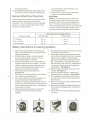
Safety instructions on sawing systems
6
1. Always wear leathergloves when handlingsaw
blade. The operator shall not wear gloves when
operating the machine.
2. All doors shall be closed, all panels replaced,
and other safety guards in place prior to the
machine being started or operated.
3. Be sure that the blade is not in contact with the
workpiece when the motor is started. The motor
shall be started and you should allow the saw to
come up to full speed before bringing the saw
blade into contact with the workpiece.
4. Keep hands away from the blade area.
See Figure A.
5. Remove any cut off piece carefully while keeping
your hands free of the blade area.
6. Saw must be stopped and electrical supply must
be cut off before any blade replacement or
adjustment of blade support mechanism is done,
or before any attempt is made to change the drive
belts or before any periodic serve or maintenance
is performed on the saw.
7. Remove all loose items and any unnecessary
workpieces from the area before starting
machine.
,.
A
B
8. Bring adjustable saw guides and guards as close
as possible to the workpiece.
9. Always wear protective eye wear when operating, servicing, or adjusting machinery. Eyewear
shall be impact resistant, protective safety
glasses with side shields complying with ANSI
Z87.1 specifications. Use of eye wear which
does not comply with ANSI Z87.1 specifications
could result in severe injury from breakage of
eye protection. See Figure B.
10. Nonslip footwear and safety shoes are recommended.
See Figure C.
11. Wear ear protectors (plugs or muffs) during
extended periods of operation. See Figure D.
12. The workpiece, or part being sawed, must be
securely clamped before the saw blade enters
the workpiece.
13. Remove cut off pieces carefully, keeping hands
away from saw blade.
14. Saw must be stopped and electrical supply cut
off or machine unplugged before reaching into
cutting area.
15. Avoid contact with coolant, especially guarding
your eyes.
c
D
8
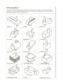
Introduction
This manual includes the operating and maintenance instructions for the Wilton 14-inch Vertical Band Saw,
Model 8014. This manual also includes parts listings and illustrations of replaceable parts. Typical operations
performed using the band saw are shown below.
RIPPING
SLICING
BEVELING
SLOTTING
SEGMENTING
SHAPING CUT
SPLITTING
ANGULAR CUT
GRINDINGRELIEF
7
STACK CUTTING
EXTERNAL CONTOUR
INTERNAL CONTOUR
THREE-DIM.CUTTING
SHAPING
COMPOUND ANGLE CUT
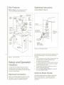
SawFeatures
OperatingInstructions
Refer to Figure 1 for key features of the
14-lnch Vari-Speed Vertical Band Saw.
Controls (Refer to Figure 2)
Blade Tension
Hand Wheel
Upper
Wheel
Door
Speed
And
Pitch
Selector
Guide
Rod
Hand
Wheel
ON/OFF
Switches
Work
Lamp
Tum CounterClockwise To
Decrease Speed
~
Lower
Wheel
Door
~
Chip Pan
(inside door)
Lube
Fitting
~
~
~
8
Figure 1: Saw Features
Setup and Operation
Installation
The frame of the vertical band saw has four
mounting holes in the base of the saw frame.
The band saw may be secured to the floor using
the four mounting holes.
Electrical Connection
Refer to the Wiring Diagram section for wiring
information. Connection to electrical power
should be made by a qualified electrician.
==
Tum
Clockwise
To Increase
Speed
Variable
Speed Crank
(turn only when
saw is operating)
Figure 2: Operating Controls
The operating controls for the saw are located on the
left side of the machine. The controls include the
following:
1. A set of start/stop push buttons, located below the
optional welder, provide a means to start
and stop the saw drive motor.
2. A variable speed control (crank), which can only
be adjusted while the saw is running, is located
below the start/stop buttons.
3. A bladetensioning hand wheel is mounted on
the top of the saw enclosure.
4. Refer to Optional Blade Welder for a description of the welder controls.
Optional Blade Welder
An optional blade welder is available on the Model
8014 vertical band saw. The welder has all the
features required to cut, weld, and anneal the
saw blade.
- - - --
Welder Features
Operatingthe Welder
(Refer to Figure 3)
(refer to Figure 4)
The welder is installed on the left side of the saw
frame. A blade cutter, provided with the welder, is
mounted on the saw frame near the panel.
WARNING: BE SURE TO WEAR EYE PROTECTION WHILE OPERATING THE WELDER TO
AVOID EYE INJURIES. USE CARE WHEN HANDLING THE BLADE AFTER WELDING TO AVOID
BURNS.
The welder has two clamps that are used to clamp
and hold the ends of the saw blade during welding.
The welder controls include a clamp pressure selector, welding and annealing pushbutton switches, and
switches for the blade grinder and welder light.
0
0
Annealing
Button
Welding
Button
Clamp
Pressure
Selector
0
I~~
ON
Light
Switch
Clamp (2)
01,
Clamp
Handle (2)
ON
Grinder
Switch
OFF
LIGHT
OFF
MOTOR
GRINDER
Blade
Grinder
1. Using the blade cutter, cut the blade to the
required length (View A).
2. Using the blade grinder, square-off the blade
ends (View B). The blade ends need to be
perpendicular to the side of the blade.
The blade ends must be square so there is
minimal gap between the ends when clamped f
or welding.
3. Insert one end of the blade in the left clamp (View
C). Position the back edge of the blade against
the back of the left clamp. Then position the end
of the blade midway between the left and right
clamps. Tighten the left clamp.
4. Insert the other end of the blade in the right
clamp. Position the back edge of the blade
against the back of the right clamp. Then butt the
end of the blade up against the other end of the
blade (the blade ends need to be in contact with
each other). Tighten the right clamp.
5. Set the clamp pressure selector switch (clockwise rotation) to the setting required for the width
of the blade being welded (see the table on the
next page).
NOTE:
0
0
There will be some resistance when
turning the switch.
Figure 3: Welder Features
({p
VIEW A
Figure 4: Operating the Welder
VIEW B
VIEWC
9
SettingBladeSpeed
Blade Width
1/8" to 1/4"
5/16" to 3/8"
1/2"
5/8"
3/4"
Clamp Pressure
Selector Setting
1
2
3
4
5
6.
Press and hold the weld pushbutton. When the
pusbutton is pressed, the right clamp moves to
the left to apply pressure to the blade ends. At
the same time, there will be sparking from the
blade ends as the blade is being welded.
7. Release the weld push button and unclamp the
left and right clamps.
8. Rotate the clamp pressure switch (clockwise) to
the zero position.
9. Center the weld between the two clamps. Tighten
the clamps.
10. The weld is hard and brittle and must be annealed
before use. To anneal the weld, quickly depress
and release Oog) the anneal pushbutton. Repeat
the depress and release process until you see a
red glow (slightly red) from the weld area.
CAUTION: DO NOT PRESSAND HOLD THE
ANNEAL PUSHBUTTON. THE WELD WILL BE
OVERHEATEDANI;)THE WELD WILL FAIL DUE TO
THE EXCESSIVEHEAT.
10
11. Release both blade clamps and remove the blade.
12. Check the integrity of the weld. Bend the blade
to form a radius in the blade at the point of the
weld. The size of the radius should be approximately the same as the radius of the saw drive
wheel. The weld must hold and not break or
crack after forming the radius. If the weld
breaks, cut away the welded area and repeat the
welding/annealing process.
CAUTION: CHECK THE BLADETO MAKE SURE
THE WELDED SECTION IS THE SAME THICKNESS
AS THE REST OF THE BLADE. IF THE BLADE IS
THICKER AT THE WELD, THE BLADE GUIDES MAY
BE DAMAGED.
13. Check to make sure the welded section is the
same thickness as the rest of the blade. If not,
grind off excess weld material using the grinder
on the welder.
WARNING: NEVER OPERATE THE SAW WITHOUT BLADE COVERS IN PLACE AND SECURED.
CAUTION: DO NOTTURN SPEED SETTING
CRANK UNLESSTHE SAW MOTOR IS OPERATING. THE SPEED SETTING MECHANISM CAN BE
DAMAGED.
1. Start the saw using the start pushbutton.
2. Refer to the Speed and Pitch selector on the left
side of the saw enclosure. Select the speed
setting for the material to be cut.
3. Turn the speed setting crank to the required
speed. Turning the crank to the right (clockwise)
increases speed. Turning the crank to the left
(counterclockwise) decreases speed.
Blade Selection
The vertical band saw is equipped with a Wilton
part number 91 08381 saw blade that is adequate for
a variety of common materials. The blade is a 10tooth, 1/2-inch multi-purpose blade. (Refer to the
speed and pitch indicator on the left side of the
vertical saw to select the blade and speed required
for various materials.)
A coarse blade is generally used for a solid steel
bar but a finer tooth blade used on a thin-wall tube.
In general, the blade choice is determined by the
thickness of the material; the thinner the material, the
finer the tooth pitch.
For very high production on cutting of special
materials, or to cut hard-to-cut materials such as
stainless steel, tool steel, or titanium, contact your
industrial distributor for more specific blade recommendations. Also, the supplier who provides the
workpiece material should be prepared to provide
you with very specific instructions regarding the best
blade for the material and shape supplied.
Setting Blade Guide Support
(Refer to Figure 5)
The blade guide support must be adjusted for the
thickness of the material to be cut. Adjust the
position of the support as follows:
1.
Loosen the blade guide support by turning the
handwheel on the front of the saw enclosure.
2.
Place the material to be cut adjacent to the blade
guide. Move the blade guide support by hand
until there is clearance between the material to
3.
be cut and the blade guide.
Tighten the handwheel.
Blade
Tension
Blade ~
Guide
Rod
Hand Wheel
I/I)~
rI
-~
I
II
illi(I 0
\V
.
"'---cU
\
~11~L1r-//~
.
~Ia.de\
Ulde
Rod
I
II
\
I I
.
Adiust Up
,
r
"
or Down
Blade
Guards
'
I
as Required!
I ld
1,,\ \
IWllIN
Idler
Wheel
\"~'
I
,
tt~ne~1
.
!~
Ii
j
I
~
~II~r~:fc1;
.. I I::-:::~j/
\.~
~
I)
Blade
GUides~~
.
0!
/
/' j
A
..
Drive
Wheel
'
Figure 5: Setting Blade Guide Support
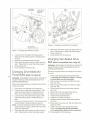
Maintenance
Cleaning
WARNING: DISCONNECT ELECTRICAL POWER
TO AVOID POTENTIAL FOR UNINTENDED START-UP
DURING MAINTENANCE. PERIODICALLY
EMPTY THE CHIP PAN (INSIDE THE LOWER
DOOR ON THE LEFT SIDE OF THE MACHINE). USE
A BRUSH TO LOOSEN ACCUMULATED
CHIPS AND DEBRIS. USE A VACUUM CLEANING
TO REMOVE ACCUMULATED DEBRIS.
Lubrication
Figure 6: Replacing Saw Blade
3.
Release tension on the saw blade by turning
the blade tension hand wheel on the top of
the band saw.
WARNING: HANDLE THE SAW BLADE WITH
GLOVES TO AVOID INJURY.
4.
Install the blade so the teeth facing downward
where the blade passes through
the worktable.
Bearings: The bearings used in vertical band saw
are pre-lubricated, sealed bearings and require no
additional lubrication.
Air Pump: Lubricate the air pump every six
months. Add oil through the oil fitting on the
front of the band saw.
Changing Saw Blades
(Refer to Figure 6)
WARNING: DISCONNECT ELECTRICAL POWER TO
AVOID POTENTIAL FOR UNINTENDED START-UP
DURING MAINTENANCE.
Follow the procedures below to change the saw blade:
1.
Open upper and lower doors on the left side of
the band saw.
2.
Remove the front and rear blade guards.
Remove the worn blade and install the new blade.
5.
6.
7.
8.
Using the handwheel on the top of the saw,
tighten the blade.
Install the front and rear blade guards.
Close the access doors and start the saw.
Observe the tracking of the blade. Refer to
Adjusting Blade Tracking if the blade does not
track properly.
Changing Saw Wheel Drive
Belts (Refer to Figure 7)
WARNING: DISCONNECT ELECTRICAL POWER
TO AVOID POTENTIAL FOR UNINTENDED STARTUP DURING MAINTENANCE
Followtheproceduresbelowto changethedrivebelt:
1. Open door on the right side of the band saw.
11
Saw Blade
Drive Belts
Upper Tension
Adjustment
Slots(2)
~'
Jt~
Drive Motor
ldDown
H
Ad'
Air Pump
Hold Down
Bolts
~~
J~:tment
~
Nuts
.
~
~
~~
~
~
~
~
Figure 8: Changing Drive Motor/Air Pump Belts
Lower Tension
Adjustment Slots (2)
Figure 7: Changing Saw Wheel Drive Belt
2.
3.
4.
5.
6.
Loosen bolts on the upper idler pulley support.
Slide upper idler pulley support to releasetension
on belts.
Removeworn beltsand installnew belts.
Slide upper idler pulley support to apply tension on
belts. Tighten bolts on upper idler pulley support.
Close access door.
Check operation of the band saw.
Changing Drive Motor/Air
12
Pump Belts (Refer to Figure 8)
6. Slide upper idler pulley support to apply tension on
belts. Tighten bolts on upper idler pulley support.
7. Close access door.
8. Check operation of the band saw.
Changing Vari-Speed Drive
Belt (Referto Exploded View, Page20)
WARNING: DISCONNECT ELECTRICAL POWER TO
AVOIDPOTENTIALFORUNINTENDEDSTART-UP
DURINGMAINTENANCE
Follow the procedures below to change the vari-speed
drive belt:
1. Removesaw wheel and drive motor belts (refer
to Changing Saw Wheel Drive Belts and Changing Drive Motor and Air Pump Belt).
2. Remove lower drive pulley (ref.#58) from lower
shaft (ref. #56).
Follow the procedures below to change the drive motor
3. Remove upper drive pulley (ref. #63) from upper
and air pump belts:
shaft (ref. #64).
1. Open door on the right side of the band saw.
4. Remove upper and lower drive pulley supports
2. Loosen bolts on upper idler pulley support. Slide
(ref. #55).
upper idler pulley support to release tension on
5. Removeand lower vari-speed mechanisms.
belts. Do not remove the saw wheel drive belts.
6. Removeworn vari-speed drive belt.
7. Install newvari-speeddrive belt.
3. Loosen bolts on lower idler pulley support. Slide
lower idler pulley support to release tension on
8. Installthe vari-speed mechanism.
belts.
9. Installthe upper and lower drive wheel supports
4. Remove worn motor drive belt. Then remove the air
(ref. #55).
pump drive belt. Install new belts as required.
10. Install upper drive pulley (ref. #63) and lower drive
NOTE: It may be necessary to loosen the drive motor
pulley (ref. #58).
11. Install drive motor and saw wheel drive belts
attaching screws to have sufficient slack to remove
the air pump drive belt.
(refer to Changing Saw Wheel Drive Belts
5. Slide lower idler pulley support to apply tension on
and Changing Drive Motor and Air Pump Belt).
12. Check operation of the band saw.
belts. Tighten bolts on lower idler pulley support.
WARNING: DISCONNECT ELECTRICAL POWER TO
AVOID POTENTIAL FOR UNINTENDED START-UP
DURING MAINTENANCE
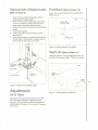
Replacement of Blade Guides
Frant/Back(Refer to Figure 10):
(Refer to Figure 9)
Loosen hex nut and tilt table to the desired position.
Tighten hex nut.
1. When removing upper blade guides, remove
blade guard from guide support.
2. When removing lower blade guides, open lower
left door to access the blade guides (the lower
blade guard is attached to the lower door).
3. Remove cap screws and washers from both blade
guides.
4. Removebladeguides.
5. Install new blade and secure with cap screws
and washers.
6. Adjust blade guides so they just touch the side of
the saw blade. Adjust position of guide seat so it
just touches the back edge of the blade.
,
\
\
\'\~
\ \
0
\
'
Table
-------------
Position Tab~--
\~\'\ ~
" \
at Desired Angle
- .'---
/
~
r-'
J~l''/
/C--
"'/
,
1
~,
~i
"
,§J
I
I
\
s=r
~~
,
~El3~
"
IL,
-A
II
,
""-I~I
Loosen~~
I
\I
I
1-1 Nut!
--1.
-
'i(
'--'--
II
Figure 10: Table Adjustment (Front/Back)
Right/Left
(Refer to Figure 11):
Loosen two screws. Using the adjustment knob, tilt
the table to the desired position. Tighten two screws.
Table
~
c
~1\\\
)
~
I
,
,-~
~~;-~
Angle
r#"L;\
Adjustmen
t'''? ''i0
?\~,~ ~. I
\
'{,ll
I
/
I
~I
Knob
11
1...lJ1
'
0//
,
,
I
Jt'< 1 <~I
',
Adjustments
Work Table
The position work table can be adjusted to tilt either
left or right (approximately 10 degrees in either
direction) The work table can also be adjsuted to tilt
approximately 45 degrees to the rear and 15 degrees
to the front).
j
'
,
Figure 9: Replacement of Blade Guides
/
1 /'-.'./
1 111 ~ ..~.
,L
,
~~~(::
~I
(x,
1
,
0 ;II '7 /
/
:J~
I
,
I
'
~!
!I
~:~~
-
~;~j
Figure 11: Table Adjustment (Right/Left)
-
,
(2)
13
Blade Tracking
(Refer to Figure 12)
WARNING: DISCONNECT ELECTRICALPOWER
TO AVOIDPOTENTIALFORUNINTENDEDSTARTUP DURINGMAINTENANCE
Blade tracking can be corrected using the following
procedure
1. Operate the saw to determine if the blade is
tracking off center. Determine if the blade is
tracking to the right or to the left.
2. To adjust tracking, open the door on the right
side of the machine. Loosen the jam nuts on
the tracking adjustment screws.
3. If the blade tracks to the right, the bottom of the
blade drive pulley (ref.#3) needs to be move
outward. Adjust the upper screw outward. Then
adjust the lower screw inward. Tighten the upper
screw against its stop. Tighten the jam nuts.
4. If the blade tracks to the left, the bottom of the
blade drive pulley (ref. #3) needs to be move
inward. Adjust the lower screw outward. Then
adjust the upper screw inward. Tighten the lower
screw against its stop. Tighten the jam nuts.
Figure 12: Adjusting Blade Tracking
5. Close the door and operate the saw. Repeat the
steps above as required to achieve proper tracking.
Troubleshooting
Fault
Excessiveblade
breakage
14
Prematureblade
dulling
Unusualwear on
side of blade
Teethmissing/ripped
from blade
Rough cuts
Probable
Cause
Suggested
Remedy
1. Incorrect speed.
1. Check Machinist's Handbook for
speed appropriate for thematerial
being cut.
2. Teethtoo coarse for material.
2. Check Machinist's handbook for
recommendedblade type.
3. Misalignedguides.
3. Adjust guides.
4. Cracking at weld
4. Longer annealing cycle.
1. Blade teeth too coarse.
1. Use a finer tooth blade.
2. Blade speed too high.
2. Reduce blade speed.
1. Blade guides worn.
1. Replace blade guides.
2. Blade guides not adjusted.
2. Adjust blade guides.
1. Blade tooth pitch too coarse for
workpiece.
1. Use blade with finer tooth pitch.
2.
2. Reduce/increase feed pressure
and/or blade speed.
Incorrect feed or speed.
3. Gullets loading up with chips.
3. Use blade with a coarse tooth
pitch-reduce feed pressure.
1. Blade teeth too coarse.
1. Use a finer tooth blade.
2. Blade speed too high.
2. Reduce blade speed.
~
~
ANNEALING PUSH BUTTON
::J
(Q
WELDING PUSH BUTTON
SWIT~
0
-.
~ITCH
LIGHT
LIGHT
Q)
(Q
~
SWITCH
Q)
3
SWITCH
AC
110V
T
SWITCH
OFF
~
Jh~
ON
SWITCH
- - ---,
R
TRANSFORMER
MOVABLE WELDING PAD
~
-0--<>
S
~
I
T t-O-o
~
S
SOURCE
.....
CJ1
T
I V
I
0--0
I'- - - - - - -
R
:u
IW
1'
M
-
- - -
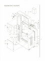
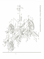
Replacement Parts
This section provides exploded view illustrations that show the replacement parts for the Model 8014 Verical
Band Saw. Also provided are parts listings that provide part number and description. The item numbers shown
on the illustration relate the item number in the facing parts listing.
Order replacement parts form:
Wilton Corporation
300 South Hicks Road
Palatine, IL 60067
TEL: 1-888-594-5866
FAX: 1-800-626-9676
Identify the replacement part by the part number shown in the parts listing. Be sure to include the model
number and serial number of your machine when ordering replacement parts to assure that you will receive the
correct part.
16
Exploded View - Enclosure
25:
-~
~
2
./'./"
./'
./'./'
./'
./"
./'./'
~~
~
~
I 17
~
o/J
~
J,
~
./
\
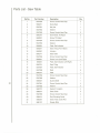
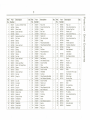
Parts List- Enclosure
18
Ref.No.
Part Number
1
5507831
Description
Frame
2
5507832
Washer
6
3
5507833
Screw
6
4
5682271
Rear Cover
1
5
5507834
Label, Oil
1
6
-------
7
5682281
Blade Guard
1
8
5507835
Washer
2
9
5507836
Screw
2
10
5507837
Set Screw
1
11
5507838
Washer
1
12
5507839
Nut
1
13
-------
14
5507840
Handwheel
1
15
5515226
Prox. Sensor, SFPM
1
16
5516376
1
17
5507841
Bracket, Prox. Sensor
Washer
18
5507842
Screw
1
19
5682261
Lamp
1
20
5507843
Enclosure, Electrical
1
21
5683781
Handle/LockAssembly,Door
2
22
5683791
Door,Bottom
1
23
5516377
Screw, Cap
1
24
5597844
Feed/SpeedChart
1
25
5507845
Door, Upper
1
26
5516378
Bolt,Hex
1
27
5682221
Chip Pan
1
28
5682241
Channel, Small Chip
1
29
5682211
Brush, Cleaning
1
30
5507846
Label, Speed Change Door Warning
1
31
5682101
Switch, On/Off
1
32
-------
Qty
1
1
33
5515283
LED Readout, SFPM
1
34
5507847
Screw
4
35
5507848
Label, Blade Direction
1
36
5681392
Blade Cutter Assembly
1
37
5507849
Screw, Socket Head Cap
2
Exploded View - Saw Table
30:
23:
@
@
~~
@
@
@---
I
I
I
~
I~
1./
0
6
~~
~
@
0
I
~
16:
13:
0@
'-</
~
I
0
e: I
~'
.
.
,
~
~e
1)
./
d'~~1
V
\~
~
I
.h
"-
~
@
@
@
@
(9
19
Parts List - Saw Table
20
Ref.No.
Part Number
1
5507850
2
5682811
3
5507851
4
Description
Screw, Socket Head Cap
Guide Seat
Qty
2
1
1
5507852
Nut,Hex
Washer
5
5507853
Screw, Socket Head Cap
2
6
5682781
Screw Seat, Tilt Adjust
2
7
5682801
Screw,Tilt Adjust
1
8
5507854
1
9
5507855
Screw, Socket Head Cap
Washer
10
5682881
Plate, Dial Indicator
1
11
5682871
1
12
5682861
Seat, Tilting (Front-Back)
Indicator
2
13
5682771
Seat,Table
1
14
5597856
Screw, Socket Head Cap
2
15
5682841
Screw, Lock (Left-Right)
1
16
568285
Plate, Dial Indicator (Left-Right)
1
17
5682761
Seat, Tilting
4
18
5507857
1
19
5507858
Plate, Dial Indicator
Rivet
6
20
5682751
Table
1
21
5507859
1
22
5507860
Screw, Socket Head Cap
Washer
23
5682921
Guard, Blade
1
24
5507861
4
25
5507862
Screw, Socket Head Cap
Washer
26
5682791
Support,Tungsten
4
27
5682811
Seat, Guide
2
28
5597863
Screw, Socket Head Cap
4
29
5682911
Rod, ElevatingGuide
1
30
5682901
Seat, Fixed, Guide Rod
1
31
5681811
Gauge, Miter
1
1
1
1
4
m
X
"'C
0
0CD
0-
<
99
CD
:E
0
~.
<
CD
()
0
3
"'C
0
:J
CD
:J
.....
en
.23
iJ
21
22
I\)
......
I\)
I\)
Ref.
No.
1
2
3
4
5
6
7
8
9
10
11
12
13
14
15
16
17
18
19
20
21
22
23
24
25
26
27
28
29
30
31
32
33
34
35
36
37
38
Part
Number
Description
Qty
5682731
5507864
5682741
5507865
5507866
5682721
5682711
5507867
5507868
5507869
5507870
9100321
5682701
5507867
5597868
5597869
9100321
5682691
5682331
5507861
5507872
5507873
5507874
5682361
-------
Locknut,Left-Hand
Thread
Washer
Wheel,Lower
Screw,HexHead
Washer
Bearing,BracketFixed
Pin,Fixed
Washer
Nut,Hex
Screw,HexHead
Spacer
Bearing
Seat,Bearing
Washer
Nut,Hex
Screw,HexHead
Bearing
Shaft,LowerWheel
Motor,1 HP,Single-Phase
Spacer
Washer
Screw,HexHead
Nut,Hex
Pump,Air
1
1
1
4
4
1
2
1
1
1
1
1
1
2
2
2
2
1
1
8
8
4
4
1
5507875
5507876
5507877
5507878
5507879
5597880
5597881
5682371
5683361
5507882
5507883
5682341
5507882
Line,Oil
Connector
Cup,Oil
Hose,Air
SDrina,Protection
Clamp,Hose
Nozzle,
Air
Pulley,AirPump
V-Belt(M21)
SetScrew
V-Belt(A40)
Pulley,Motor
SetScrew
11
1
1
1
1
1
1
1
1
1
1
1
1
Ref.
No.
39
41
42
43
44
45
46
47
48
49
50
51
52
53
54
55
56
57
58
59
60
61
62
63
64
65
66
67
68
69
70
71
72
73
74
75
75-1
76
Part
Number
5682671
5507884
5507885
5682381
5507886
5507887
5682391
5682401
5682411
5682521
5507888
5587889
5682421
5680381
5680391
5682441
5682451
5587890
5682321
5682351
5587890
5507891
5507882
5682311
5682561
5507893
5507894
5507895
5682541
5682531
5507896
5680521
5507897
5507898
5682511
9100331
5680501
5680381
Description
Ring,Fixed
Screw,SocketHeadCap
Washer
Bolt,Fixed
Washer,Lock
Washer,
Flat
Plate,SpringGuard
Spring
Pulley,Stepless
(Right)
Pulley,Stepless
Adi.(Right)
Key
SetScrew
Pulley,Stepless
(Left)
Ring,Locking
Bearina
Seat,Bearing
Shaft,Stepless
(Spring)
Screw,HexHead
Pulley
Pulley,LowerWheel
Screw,HexHead
V-Belt(A55)
SetScrew
Pulley,Stepless
(Adjustable)
Shaft,Stepless
(Adjustable)
Screw,HexHead
Washer,
Lock
Washer,
Flat
Pulley,Stepless
Adj.(Left)
Belt(775VB
25/30)
Pin,Roll
Pin,Spring
Washer
Screw
Shaft,SteplessAdjustment
Bearing
Ring,Lock
Ring,Lock
Qty
1
4
1
1
1
1
1
1
1
1
2
1
1
4
4
1
1
1
1
1
1
1
1
2
1
2
2
2
1
1
1
1
5
5
1
1
1
1
Ref.
No.
Part
Number
76
77
77-1
78
79
80
81
82
83
84
85
86
5680381
5507899
5507800
5507901
5507902
5682471
5507903
5507904
5682481
5680471
5507905
5680481
87
88
5507906
5682301
89
90
91
92
93
5682611
5507907
5507908
5507909
9108381
94
95
96
5682591
5682601
5507910
97
98
99
100
101
102
103
104
105
106
107
5507911
5682651
5682641
5682631
5507912
5507913
5507914
5682621
5507915
5507916
5682581
Description
Ring,Lock
Screw,SocketHeadCap
SetScrew,DogPoint
Washer,Lock
Screw,SocketHeadCap
Handle,Plastic
Screw,SocketHeadCap
Washer
Handle,Adjustment
Handwheel,
Adjustment
SetScrew
Seat,Adjustment
Handwheel
Label,Speed
Box,Stepless
Variable
Speed
Nut,Lock
Washer,Lock
Bearing
Ring,Snap
Blade
(1/2x 0.025x 110in.Long)
Ring,Rubber
Wheel,Upper
MountingPlate,
UpperWheel
Shaft
Nut,LeadScrew
LeadScrew
Way,LeadScrewNut
Pin,Spring
Screw,SocketHeadCap
Washer
FixedPiece
Washer
Screw,HexHead
Handwheel
Qty
1
3
1
1
6
6
2
1
1
1
1
1
1
1
1
1
2
1
1
2
1
1
1
l'
1
1
1
1
1
1
4
4
1
""U
~
::+
en
r
en
r-+
I
0
~.
<
CD
()
0
3
-C
0
::J
CD
::J
r-+
en
Exploded View - Welder
..
,;?)
"Q
/)
Cd'
0
..
\
\q"
t!Je;
'"
~
\"
.."
\°
G/'
(;)
\0
\ \" "\
6J '\
\
\
\ \
\;;
e\
\, 'f
\
\'\
@
\ @
~'Q) ~
~\\
" \\
\'
,,'I.
\\
,\
'.3/
I\)
+--
Ref.
No.
Part
Number
Description
1
2
3
4
5
6
7
8
9
10
11
12
12A
12B
13
14
15
15A
16
17
18
19
20
21
22
23
24
25
26
27
28
29
30
31
5507917
5507918
5507919
5683151
5507920
5507921
5507922
5683031
5507923
5507924
5683241
5681711
5681711A
5681711B
5683281
5507925
5681631C
56816310
5683251
5683191
5683181
5507926
5507927
5683261
5507928
5683261
5507929
5507930
5507931
5683321
5508413
5507935
568331
5507936
Nut,Hex
Washer, Lock
Washer, Flat
Wheel, Grinding
Spacer
Screw
Washer
Name Plate
Screw, Socket Head Cap
Washer, Flat
Panel,Welding
Motor,Grinder(115Volts)
Motor,Grinder(220 Volts)
Motor,Grinder(440 Volts)
Switch, On/Off
Bracket, Transformer
Transformer (220 V/2 KVA)
Transformer (440 V/2 KVA)
Block, Sliding
Switch, Microwave
Base, Limit Switch
Nut, Hex
Screw
Spring
Screw
Spring
Screw
Washer, Lock
Washer, Flat
Screw, Pressure Cross
Nut
Washer
Cam, Pressure
Shaft
Qty
Ref.
No.
1
1
1
1
1
4
4
1
6
6
1
1
1
1
1
2
1
1
1
1
1
2
1
1
1
1
1
1
1
1
1
1
1
1
32
33
34
35
36
37
38
39
40
41
42
43
44
45
46
47
48
49
50
51
52
53
54
55
56
57
58
59
*
*
*
*
Part
Number
5683331
5507937
5507938
5507939
5507940
5507941
5507942
5683171
5683271
5507943
5507944
5507945
5683081
5683091
5683111
5683121
5683041
5683001
5683141
5683071
5683011
5683131
5683021
5507946
5507950
5507951
5507952
5507953
5507529
5507947
5597948
5507954
Description
Plate, Pressure Cross
Screw
Screw
Washer
Screw
Button, Weld
Button,Anneal
Support, Cam Shaft
Pad,A Sliding
Screw
Washer
Screw, Flat Head
Cover,Working Lamp
Lamp
Knob, Clamp Pressure
Plate, B Insulating
Base, A Welding
Base, B Welding
Shaft, Centerless Handle
Handle,A Centerless
Handle, B Centerless
Ring, CLock
Knob, Handle
Screw, Set
Screw
Screw
Washer, Lock
Washer, Flat
Relay
Transformer,Control
Strip,Terminal
Guard, GrindingWheel
* Noted items not illustrated.
Qty
1
4
1
1
1
1
1
1
1
4
4
5
1
1
1
1
1
1
2
1
1
2
2
2
1
1
2
2
1
1
1
1
""U
~
::1en
r
en
f"""'to
I
:E
CD
a.
CD
--,:
Notes:
25