1
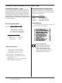
CL1000 Ceiling Light
OWNER’S MANUAL
Marus
11727 Fruehauf Drive
Charlotte, NC 28273 USA
Warranty
The Marus Light was thoroughly inspected and tested in accordance with rigid specifications and standards of
Marus quality.
All of our products sold to and installed by dealers are guaranteed to be free from defects in workmanship
and materials for five years from date of purchase - providing all installation and service is done in accordance
with procedures as outlined in our instructions.
During that period, we will replace any defective part at no charge. We WILL NOT be responsible for dealer or
service company labor charges or shipping charges to the Marus factory.
This guarantee does not cover normal wear, stains, cuts or scratches of surface finishes or parts sold to
O.E.M. customers.
Staining, discoloration, or deterioration of the equipment caused by disinfectant solutions is not covered under
the warranty.
We will pay the return freight charges from the factory to the dealer. This guarantee does not cover damage
resulting from improper installation, misuse, or accidents incurred in shipping and handling.
All claims against the freight carrier must be initiated at the time the damaged items are received. The claim is
the responsibility of the customer.
We are constantly striving to improve our products. Therefore, we reserve the right to make modifications
without the need for prior notification. Nor are we obliged to modify previously manufactured items.
It is the user’s responsibility to read and understand the contents of this manual. This
manual contains important information relative to hazards to personnel and property if
this equipment is not installed, used and/or maintained as instructed.
Technical Support
Tech Support: 800-304-5332
FAX: 888-861-9366
Web site: www.marus.com
Marus
11727 Fruehauf Drive
Charlotte, NC 28273Printed in the U.S.A.
70-050R228 Rev 11 02/12
Table of Contents
General Information................................................................................................................................ 2
Definition of Symbols....................................................................................................................... 2
Product Disposal.............................................................................................................................. 2
Interference with Electromedical Devices........................................................................................ 2
Incompatible Devices and/or Accessories....................................................................................... 2
Obtaining Technical Literature.......................................................................................................... 2
Product Identification....................................................................................................................... 2
Safety Notes........................................................................................................................................... 3
Storage Conditions.......................................................................................................................... 3
Technical Specifications for the Dental Light.......................................................................................... 4
Technical Description — Light.......................................................................................................... 4
Electrical Specifications................................................................................................................... 4
Light Specifications.......................................................................................................................... 4
Replacement Parts for Dental Lights............................................................................................... 4
Safety Markings............................................................................................................................... 4
Device Classification........................................................................................................................ 4
Cleaning the Light................................................................................................................................... 5
WARNINGS, DISINFECTING & STERILIZATION - LIGHTS........................................................... 5
Infection Control............................................................................................................................... 5
Chemical Disinfection....................................................................................................................... 5
Unacceptable Disinfectants.............................................................................................................. 5
Conditionally Acceptable Disinfectants*........................................................................................... 5
Cleaning Reflector and Cover.......................................................................................................... 6
Cleaning Painted Surfaces............................................................................................................... 6
Dimensions............................................................................................................................................. 7
Suggested Mounting Methods................................................................................................................ 8
Suggested Installation on Wood Framed Ceiling............................................................................. 9
Wood Structure for Suspended Ceiling.......................................................................................... 10
Suggested Installation on Suspended Ceiling............................................................................... 10
Metal Structure for Suspended Ceiling.......................................................................................... 11
Electrical Requirements....................................................................................................................... 11
Ceiling Light Installation Instructions.................................................................................................... 12
Overview / Replacement Parts....................................................................................................... 15
Controls................................................................................................................................................ 15
On-Off Switch................................................................................................................................. 15
Intensity Switch.............................................................................................................................. 15
Spare Bulb..................................................................................................................................... 15
Bulb Removal and Replacement.................................................................................................... 16
Light Focus Adjustments...................................................................................................................... 17
Yoke Pivot Friction Adjustment............................................................................................................. 17
Flex Arm Adjustment............................................................................................................................ 19
Electromagnetic Compatibility.............................................................................................................. 20
Electrical Schematics........................................................................................................................... 24
Checklist............................................................................................................................................... 26
1
General Information
Definition of Symbols
The following symbols may be used throughout
this manual:
CAUTION. Failure to carefully follow the described
procedure may result in damage to the equipment.
WARNING. Failure to carefully follow the described
procedure may result in damage to the equipment
and/or operator/patient injury.
Risk of electrical shock present.
Ensure power is disconnected before attempting
this procedure.
Product Disposal
Contact your local authorized dealer for proper disposal
of the device to ensure compliance with your local
environmental regulations.
Interference with Electromedical
Devices
To guarantee the operational safety of electromedical
devices, it is recommended that the operation of mobile
radio telephones in the medical practice or hospital be
prohibited.
Strong EMI sources such as electro surgery units or
x-ray units may affect performance. If performance
problems occur, move the light to another electrical
circuit or physical location.
Incompatible Devices and/or
Accessories
Protective Earth (Ground)
For reasons of product safety, only original manufacturer
devices & accessories approved for this product, or
accessories from third parties which have been released
by the manufacturer may be used. It is the user’s risk
when using non-released accessories are used.
Manufacturing date
Obtaining Technical Literature
AC (Alternating Current)
Waste Electrical and Electronic Equipment
Type B Equipment
(Protected against electrical shock)
Dangerous Voltage
Electrical Testing Lab
The manufacturer will make available on request circuit
diagrams, component parts lists, descriptions, calibration
instructions or other information that will assist technical
personnel to repair and replace serviceable items.
Product Identification
This dental light can be identified by its product label,
located on product. This label states the light model and
serial number, electrical specifications, manufacture
date and safety classification. Note the SAMPLE labels
shown below.
Identification mark that indicates the product
complies with the health & safety requirements
as published by European Directives.
Marus
MN
SN
Authorized European Representative:
Dental Light
2
MN
SN
Dental Light
230 VAC, 50HZ, 0.6A
IEC Type B, Class 1, IPX4
92163 • Rev.5 • 02/12
Operation Mode: Intermittent
Conforms to:
EN60601-1-2,UL60601-1
Certified to:
CAN/CSA - C22.2 NO.601.1
59768
WARNING: This product is intended
for use by trained dental/medical
professionals only.
11727 Fruehauf Drive
Charlotte, NC 28273 USA
115 VAC, 60HZ, 1.09A
IEC Type B, Class 1, IPX4
92162• Rev.5 •02/12
Medical Device and QA Services
76, Stockport Road
WA15 7SN
United Kingdom
e-mail: [email protected]
Marus
11727 Fruehauf Drive
Charlotte, NC 28273 USA
Operation Mode: Intermittent
Conforms to:
EN60601-1-2,UL60601-1
Certified to:
CAN/CSA - C22.2 NO.601.1
59768
Safety Notes
The pre-installation must be performed according to the requirements in our ‘Pre-installation Instructions’.
As manufacturers of electro-medical products we can assume responsibility for safety-related performance of
the equipment only if maintenance, repair and modifications are carried out only by us or agencies we have
authorized for this purpose, and if components affecting safe operation of the unit that may be needed are
replaced with original parts.
We suggest that you request a certificate showing the nature and extent of the work performed, from those
who carry out such work, and specify that the certificate show any changes in rated parameters or working
ranges, as well as the date, the name of the firm and a signature.
WARNING: Rotational stops are
designed for a maximum force limit of
30 lbs. If rotational stops are broken
immediately take the equipment out of
use and have the equipment serviced.
Operation of damaged equipment
could result in injury to the operator
and/or patient.
WARNING: Failure to install set
screws & roll pin per Installation
Instructions could result in injury or
damage to equipment.
WARNING: The light is not to be used
in rooms where an explosion hazard
exists.
WARNING: Power cords and their
associated parts cannot be substituted
without increased risk of electric
shock or fire. Use manufacturerapproved replacement parts only!
Power cords must be installed by
qualified personnel. Make sure all
service loops, strain reliefs, and cord
guards are in place and that line,
neutral and ground wires are secured.
CAUTION: Only authorized service technicians should attempt to service
this equipment. Use of other than
authorized technicians will void the
warranty.
WARNING: Failure to disinfect the
dental operating light between patients
could expose user/patient to cross
contamination and bio-burden/biocontamination.
WARNING: No modification of this
equipment is allowed.
CAUTION! Use a licensed electrician
for all wiring.
WARNING: To avoid risk of electric
shock, this equipment must be
connected only to supply mains with
protective earth.
WARNING: To avoid risk of burn injuries
do not touch the light reflector during
operation.
WARNING: To avoid risk of injury, avoid
contact with sharp edges on dental
lights.
WARNING: This product must be
disinfected before use.
Storage Conditions:
-55°C to +50°C
10% to 90% Relative Humidity
3
Technical Specifications for the Dental Light
Technical Description — Light
The dental light is used for illuminating the oral cavity during the performance of dental procedures. The
position and direction of the light can be adjusted as
needed by the dentist. The light source is a halogen
bulb designed to operate on low voltage. It has two
intensity settings. The low voltage is supplied through a
transformer which is located at the top of the light pole
or in the junction box.
Cycles
60 HZ
50 HZ
The following represents a condensed list of
replacement parts that may be consumed during
normal use. See your dealer for a more comprehensive list of components.
PART #
DESCRIPTION
70-22186���������������� REFLECTOR, GLASS
70-20289���������������� LIGHT SHIELD
70-30441���������������� REPLACEMENT BULB
70-014R304������������ FUSE, 4 AMP, 3 AG (115V)
70-014R303������������ FUSE, 2 AMP, 3 AG (230V)
Safety Markings
Electrical Specifications
Volts Dental light: 115 VAC
230 VAC
Replacement Parts for Dental Lights
Amps
1.09 A ~
0.6 A ~
The following warning label may be located on or
near the light’s transformer enclosure:
Replacement fuses for unit light
(located in panel near transformer):
115V: 4 AMP, 3 AG (P/N 70-014R304)
230V: 2 AMP, 3 AG (P/N 70-014R303)
IEC Medical Device Classification
Classification:
1
Type:
B
Operation Mode:
Intermittent
Splash Protection:
IPX4
Light Specifications
Halogen Lamp: 24 Volts, 100 Watts
Input Voltage: 110V/220 V, 60/50 Hz
Output Voltage: High 23V, Low 21V
Color Temperature: 4500 Degrees Kelvin
Light Intensity (Lux): High 25,000, Low 18,500
4
Focal Distance: 27 in.
Illumination Area: 3 in. x 8 in. at Focal Distance
Approx. Weight: 9.09 kg. (20 lbs.)
Technical Information
Device Classification
The dental light is classified as
Class 1 device under rule FDA
CFR 21, Class I device under
Health Canada guidelines, and a
Class I device under rule 11 of the
MDD 93/42/EEC of Annex IX.
Cleaning the Light
The equipment can be cleaned with a solution of mild detergent and warm water. A variety of surface disinfectants are available for use
in dental treatment rooms. Some of these can cause discoloration of painted, plated or anodized surfaces with repeated use. This can
be minimized by careful adherence to the disinfectant manufacturer’s instructions and by frequent washing with soap and water.
If you use an iodophor, it is especially important that you follow up with an iodophor neutralizer.
IMPORTANT: Do not use powdered cleansers, scouring pads or abrasive scrubbers on any of the
painted, plastic or metal surfaces of this light. To remove dried-on material, use a soft bristled brush
and a solution of mild detergent.
WARNINGS, DISINFECTING & STERILIZATION - LIGHTS
Infection control in the dental office continues to be a
high priority for our customers and end users. OSHA,
the ADA and the CDC are also involved in this complex
issue. The Manufacturer will not attempt to specify the
required intervals for disinfection nor can it recommend
the overall best surface disinfectant. Please refer to
the:
Infection Control
Recommendations published by the American Dental
Association for further information. The question is often
asked, “What should I use to disinfect my dental unit,
chair and light?” This question is more complex than it
seems because of the wide variety of products on the
market as well as formulations of the products changing
to meet the needs of increased asepsis.
barriers should be used and changed between patients. The
barrier technique will ensure maximum long term durability of the
surfaces and finishes of the equipment.
Chemical Disinfection
Regardless of the chemical disinfectant used, it is imperative
that the equipment be thoroughly washed with mild soap and
warm water at least once per day. This wash down will minimize
the harmful effects of chemical disinfectant residues being
allowed to accumulate on the equipment. When using chemical
disinfectants, always pay strict attention to the manufacturer’s
disinfectant directions. When using concentrated disinfectants,
measure the concentrate carefully and mix according to package
directions. Disinfectant solutions that are relatively harmless to
surfaces at their recommended strengths can be corrosive at
higher than recommended dilution ratios.
Barrier Technique
The Manufacturer strongly advocates the barrier technique
be used whenever possible to preserve the finish and
appearance of the equipment. Wherever possible disposable
Unacceptable Disinfectants
These disinfectants will harm the surface finishes of
dental equipment and are not recommended. Use of
these products will void your warranty.
Chemical Composition
Strong Phenols/Phenol Alcohol combinations
Sodium Hypochlorite/Household Bleach
Sodium Bromide
Strong Alcohol
Household Cleaners (Dental Equipment Only)
Citric Acids
Iodophors**
Ammonium Chloride
Accelerated Hydrogen Peroxide (0.5%)
Conditionally Acceptable Disinfectants*
These disinfectants have been found to be the least
harmful to the equipment surfaces by our test methods.
Chemical Composition
Phthalaldehyde
Quaternary Ammonium
Glutaraldehyde
CAUTION
Only disinfect by wiping, no spray disinfection. Please
be aware that the manufacturer expressly rejects any
claims for warranty or damages when using other
cleaning and disinfections solutions.
warranty expressed or implied that these disinfectants
will not damage the surface finishes. Damage and
discoloration of the surface finishes are not covered
under the warranty.
*The Manufacturer makes no representation as to the
disinfectant efficacy of these products. We make no
**Iodophor-based disinfectants will cause yellow staining
on many surfaces.
5
CLEANING YOUR LIGHT
Cleaning Reflector and Cover
NOTE: Use only denatured alcohol to clean the glass reflector. Use only mild soap and water to clean
the plastic reflector cover.
Do not use any solvents, abrasives, abrasive cloths or cleaners,
as they may damage the coated surface of the reflector.
Be sure the electrical supply is turned off and the light is cool before attempting any cleaning or polishing.
Remove the bulb shield, cover and bulb for full access to the reflector. (See “Bulb Replacement” for bulb
removal).
Use a clean, soft** facial tissue dampened with denatured alcohol and gently wipe the surface of the reflector and the bulb. The plastic reflector cover may be gently washed with soap and water and dried using a soft
towel.
Cleaning Painted Surfaces
The painted surfaces of your light can be cleaned by simply wiping with a damp cloth. No other protective
coating is required to preserve the permanent luster of the painted surface.
CAUTION: Placing aluminum foil over the lamp handles for barrier asepsis will cause permanent discoloration of the handles. We recommend covers specifically manufactured for this purpose. Discoloration of the
handles caused by the above is not covered under warranty.
**We recommend Puffs facial tissues.
NOTE: The plastic reflector cover must always be in place when light is used because it will
catch bulb particles in the rare event a bulb should break; also, it will keep abrasive material
away from the coated surface of the reflector.
6
Dimensions
12”
21-1/2” - 26”
23 1/2”
28”
TRAVEL
Figure 1
Location
A typical location for mounting the ceiling mount light is relation to the dental chair for a right-handed operator
is shown in Figure 2. Mounting for a left-handed operator would be mounted on the opposite side of the chair.
This mounting location can be altered to suit the individual’s preference or the building construction.
Height
The maximum ceiling height that can be accommodated by available suspension tubes is 10’-6”; the minimum
being 8’.
Refer to the chart for proper suspension tube to use.
Suspension Tube Chart
Ceiling Height
Tube Part No.
Length (inches)
8’
52R252-1
17”
8’6”
52R270-1
23”
9’
52R271-1
29”
9’6”
52R272-1
35”
10’
52R273-1
41”
10’6”
52R274-1
47”
7
Suggested Mounting Methods
TYPICAL POSITION OF CEILING MOUNT
IN RELATION TO DENTAL CHAIR
12”
MOUNTING LOCATION
FOR RIGHT-HANDED
OPERATOR
18”
18”
12”
Figure 2
8
MOUNTING LOCATION
FOR LEFT-HANDED
OPERATOR
Suggested Installation on Wood Framed Ceiling
CEILING JOISTS
16” O.C.
1 INCH
MOUNTING PLATE
w/ COLLAR
POWER SUPPLY
CONDUIT
FINISHED CEILING
MATERIAL
POWER CONDUIT COMES
THROUGH HOLE 2-1/2”
OFFSET FROM CENTER.
NEW CONSTRUCTION
Figure 3
CEILING JOISTS
16” O.C.
1 INCH
36” x 16” x 3/4”
PLYWOOD OVER
FINISHED CEILING
Figure 4
(6) 1/4” LAG SCREWS
3” LONG
EXISTING CONSTRUCTION
9
Suggested Installation on Suspended Ceiling
SUGGESTED INSTALLATION ON SUSPENDED CEILING
SUGGESTED INSTALLATION ON SUSPENDED CEILING
FIXED CEILING
FIXED CEILING
CEILING JOIST
MOUNTING PLATE
w/ COLLAR & POST
CEILING JOIST
MOUNTING PLATE
w/ COLLAR & POST
SUSPENDED
CEILING
COVER
SUSPENDED
CEILING
COVER
MOUNTING PLATE
w/ COLLAR & POST
MOUNTING PLATE
w/ COLLAR & POST
SUSPENDED
CEILING
COVER
SUSPENDED
CEILING
COVER
FIGURE 5 - ATTACHING COVER
FIGURE 5 - ATTACHING COVER
FOR SUSPENDED CEILING
Wood StructureWOOD
for STRUCTURE
Suspended
Ceiling
WOOD STRUCTURE FOR SUSPENDED CEILING
CEILING JOISTS
CEILING JOISTS
SUSPENDED CEILING
SUSPENDED CEILING
MOUNTING PLATE
w/ COLLAR & POST
COVER
MOUNTING PLATE
w/ COLLAR & POST
COVER
CEILING JOISTS
CEILING JOISTS
1-1/2” THICK
PLYWOOD
1-1/2” THICK
PLYWOOD
FIGURE 6
FIGURE 6
10
BE SURE TO BRACE
IN BOTH DIRECTIONS
BE SURE TO BRACE
IN BOTH DIRECTIONS
Metal Structure for Suspended Ceiling
USE METAL MASONRY ANCHOR
WHEN REQUIRED
3/8” BOLTS
FINISHED CEILING
SUSPENDED CEILING
LEVELING PLATE
1-1/2” x 3/4” x 1/8” CHANNELS
WELDED TO PLATE
STEEL PLATE
1/8” THICK
COVER
(6) 3/8” BOLTS
EACH BOLT MUST SUPPORT
AT LEAST 75 LBS.
FIGURE 7
Electrical Requirements
The 115VAC/230VAC service line for the ceiling light should be evaluated and installed by a
licensed electrician in accordance with local electrical codes.
We recommend that a wall switch be installed in the power supply to facilitate servicing
and protect the light transformer in the vent of power surges while the light is not in use (i.e
electrical storms).
11
Ceiling Light Installation Instructions
1. Refer to figure #2 for proper location of the ceiling light in relation to the dental chair.
Although traditional methods dictate mounting the light to the left side of the chair for a right-handed
operator and vice-versa for left-handed, careful consideration should be given to mounting location,
especially to prevent interference with x-ray units. Also consider which side of the chair the patient enters.
The light will function and position the same regardless of which side of the chair it is mounted on.
Evaluate the construction of the ceiling. See included drawings for suggestions on the best support
method to use, based on whether you have a conventional or suspended ceiling.
2. After the required support structure is in place, locate and remove from the shipping box the following
items:
A. Ceiling mounting plate
B. Ceiling post
C. Installation hardware kit
3. Attach the ceiling mount plate to the support structure using the supplied lag screws or other appropriate
hardware as dictated by support method employed. Be certain that the hardware employed can withstand
a force of 75 lbs. at each attachment point.
4. Route the power cord through the ceiling post and slip the post into the socket on the ceiling plate. Align
the retainer bolt holes in the post with the holes in the post socket and install the retainer bolt. Tighten
firmly. (See figure 9).
5. Level the post front to back. Move the level 90 degrees and repeat the above procedure with the remaining screws for leveling side to side. Recheck level in both directions; then fully tighten all leveling screws (
A magnetic level works best).
6. Turn the power to the ceiling light circuit off and make the necessary electrical connections. We recommend that a licensed electrician make the required power connections (See figures 9 & 10).
7. Place the mounting plate cover halfway up the ceiling post with the cover retaining collar below it. Lightly
tighten the setscrew to temporarily hold the cover in position. CAUTION: Do not overtighten the set screw.
It will mark the painted post.
8. Place the locking tab retaining collar on the post just above the locking tab slot and lightly tighten the set
screw (See cautionary note in Step 7). Install the stop screw in the light adapter according to which side
of the chair the light is mounted on. (See figure 10).
9. Grease the light adapter and the inside of the bottom of the ceiling post using supplied lubricant. Have an
assistant hold the light assembly with the adapter near the bottom of the ceiling post. Plug the short male
cord into the female coiled cord firmly, being certain that this plug makes a tight connection so as not to
become disconnected in the future.
10. Slide the light adapter into the bottom of the ceiling post until it bottoms. Look into the slot to be sure the
stop screw is not within the confines of the slot. Now place the locking tab into the slot in the side of the
ceiling post. (See figure 10). The locking tab fits flush into the ceiling post. Now loosen the set screw on
the locking tab retaining collar and lower it over the slot. Align the collar with the bottom of the post and
tighten the set screw firmly. The assistant supporting the light can now release it.
12
11. Check the light for freedom of movement and for any drift when positioned. Recheck the post and make
any necessary leveling adjustments. Raise the ceiling plate cover to the top of the pole and tighten the set
screw of the cover stop collar to hold the cover in place.
12. Turn on the power switch and check the light for proper operation. The switch has three positions: high,
medium, and low. The light is factory preset at a 27” focal distance. This can be adjusted to suit the operators preference.
13. On some applications in offices with low ceilings, an over travel stop may be needed to prevent contact
with the ceiling. This is supplied in the installation kit. (See figure 8).
Figure 8
13
Power Supply
Access Hole
Ceiling Mounting
Plate
Junction Box
Safety Bolt
Post Socket
Suspension Tube or
Ceiling Post
(Refer to chart on Pg. 4)
Ground
Terminal
Stop Collar
Ceiling Plate
Cover
Coiled Cord
Figure 9
Locking Tab
Retaining Collar
Set Screw
Suspension Tube or
Ceiling Post
(Refer to chart on Pg. 4)
Locking Tab
Apply Lubricant
Retaining Ring
Light
Adapter
Stop
Screw
Figure 10
14
Overview / Replacement Parts
Cover
52R523-1
Set Screw
022R046
Set Screw
022R006
Cover Retainer
52R256
Front End Cap
52R110
Rear End Cap
52R121
Bushing Retainer
52R255
Lower Transformer
Cover
22097
End Cap
52R170
Upper Transformer
Cover
52R146
Bezel
52R450
Serial# / Model#
On / Off Switch
52R442
Spare Bulb
Intensity Switch
014R306
Light Handle
52R438-1
Yoke Pivot Cap
22076
Reflector Shield
52R430
Lamp Shield
85R209
Lamp
014R207
Reflector
52R412
Figure 11
Controls
On-Off Switch
The on-off switch is located on the control panel directly above the light reflector. The long toggle provides
easy, one-motion movement to “flick” the light on or off. When the handle is in the up position, the light is
on, the down position turns the light off.
Intensity Switch
A 3-position, rocker-type switch is located adjacent to the on-off switch on the control panel. Depressing the
upper portion of the switch places the intensity control in the “HIGH” position allowing the light to emit its
maximum brilliance. An intermediate or “MEDIUM” intensity is obtained by placing the switch in the in-between position and the lowest intensity by depressing the lower portion of the switch.
Spare Bulb
The Marus light is equipped with a spare bulb in the rear of the light head. If the bulb should happen to fail,
replace it with the spare bulb provided. See Bulb Replacement section, page 16.
15
Adjustments
Bulb Removal and Replacement
Note: For maximum reliability and optimum operation, always use Marus replacement bulb #014R207.
WARNING!
Do not attempt to remove the bulb for 2 minutes after the light has been
turned off or until the bulb has cooled.
To Remove Bulb
The bulb shield is secured by a twist-lock. To remove the shield, twist counterclockwise and pull straight outward until it clears the bulb and reflector shield and let hang on the tether out of the way; then lift off the cover.
The bulb is a two-prong push-in type with one prong larger than the other to prevent improper installation. To
remove the bulb, grasp the base of the bulb and pull straight outward; a slight side-to-side rocking motion will
work the bulb loose.
Always grasp the bulb by the base when inserting. Do not touch bulb
or reflector. If the bulb or reflector have been handled or touched,
they MUST be wiped clean using denatured alcohol before putting
into operation.
Turn 1/8 Clockwise
to lock - logo should
be level
Tether
Figure 12
To Replace Bulb
Grasp the bulb by the base, align the matching pins and holes and press the bulb in firmly until it bottoms.
Wipe the glass portion clean with denatured alcohol. Place the reflector cover over the reflector and replace
the bulb shield in the reverse manner from which it was removed. Replace the shield by pushing it straight in
and twisting 1/8 turn clockwise. BE CERTAIN THE BULB SHIELD IS LOCKED SECURELY IN PLACE PRIOR
TO OPERATING THE LIGHT! The logo on the front of the bulb shield will be straight and level when the
shield is correctly locked in place.
16
Light Focus Adjustments
Note: Focus adjustment should be checked each time a new bulb is installed.
1. Place a white paper or cardboard sheet in front of the light* 27 inches from the foremost surface of the
bulb shield (or turn the light toward wall at the same distance).
2. Turn the knob at the rear of the light frame as shown in figure 13.
*Adjustment may be made any distance from 24 to 39 inches if operator prefers a different focal distance.
3. Turn the knob clockwise or counter-clockwise until the sharpest pattern is obtained at the desired range.
Figure 13
Yoke Pivot Friction Adjustment
Vertical
Note: If the light head pivots too freely vertically, an adjustment can be made at the location shown above on
either side of the light.
1. Remove the yoke cap on both sides of the yoke by pulling them straight out.
2. Loosen the two set screws about 1-1/2 turns (one on each side) at the yoke pivot using a 1/16 hex head
wrench.
3. Use a common screwdriver to tighten the yoke pivot adjustments. Tighten each side equally. Do not over
tighten. Be careful not to damage the wires that come through the yoke pivot adjustment screws.
4. Retighten the set screw and replace the yoke caps.
17
Yoke Pivot Friction Adjustment
Horizontal
Note: If the light head pivots too freely horizontally, an adjustment can be made as follows:
1. Remove the four screws located at the rear of the light head using a 7/64 hex head wrench. Remove the
rear cover (see figure 14). Adjust the tension screw until the desired tension is set.
2. Replace rear cover and install the four screws. The 2 longer screws go on top and the shorter screws go
on the bottom.
Figure 14
18
Flex Arm Adjustment
Vertical
1. Remove the two flex arm cover screws using a flat head screwdriver. (See figure 15).
2. Remove the flex arm cover.
3. Using a 1/2” wrench or socket, adjust the tension bolt until the desired tension is set. Turn clockwise for
more tension, counter-clockwise for less tension.
4. Replace cover and end caps.
FLEX ARM
COVER
TENSION
BOLT
Figure 15
Horizontal
Note: Flex arm sways from side to side and will not hold a steady position.
1. Make certain that the horizontal solid arm is level. (See figure 16).
Figure 16
19
ELECTROMAGNETIC COMPATIBILITY
MEDICAL ELECTRICAL EQUIPMENT ELECTROMAGNETIC COMPATIBILITY
(Instructions for use)
ELECTROMAGNETIC COMPATIBILITY
Electrical medical devices are subject to special EMC safety measurements and as a result the equipment
must be installed according to the installation instruction manual.
PORTABLE ELECTRONIC DEVICES
Portable and mobile high frequency electronic communications equipment may interfere with electronic
medical devices.
STATIC SENSITIVE DEVICES
Where labeled this equipment contains static sensitive devices that require special precautions when handling.
At a minimum a grounded wrist strap that is connected to ground stud should be worn to reduce the possibility
of damage to the light.
MEDICAL ELECTRICAL EQUIPMENT
ELECTROMAGNETIC COMPATIBILITY
(TECHNICAL DESCRIPTION)
ATTENTION
OBSERVE PRECAUTIONS
FOR HANDLING
ELECTROSTATIC
SENSITIVE DEVICES
ELECTROMAGNETIC COMPATIBILITY testing has been done for this product.
ACCESSORY USE
Using accessory devices not specified by the manufacturer for use with their equipment may result in an
increase of electromagnetic emissions and/or a decrease in electromagnetic immunity of the system. Do not
use any accessories not authorized or approved by the manufacturer.
INTERFERENCE FROM OTHER EQUIPMENT
If other equipment is used adjacent to or stacked with this equipment the system must be observed to verify
normal operation.
20
ELECTROMAGNETIC COMPATIBILITY
Guidance and manufacturer‘s declaration-electromagnetic immunity
This product is intended for use in the electromagnetic environment specified below.
The customer or the user of this product should ensure that it is used in such an
environment.
IMMUNITY TEST
IEC60601 TEST LEVEL
COMPLIANCE LEVEL
ELECTROMAGNETIC
ENVIRONMENT GUIDANCE
ELECTROSTATIC DISCHARGE (ESD) IEC 61000-4-2
61000-4-2
+/-6 kV contact
+/-8 kV air
ELECTRICAL FAST
TRANSIENT/BURST
IEC 61000-4-4
+/-2 kV for power supply lines +/-2 kV for power supply lines
+/-1 kV for input/output lines
Not applicable, No I/O lines
Mains power quality should be
that of typical commercial or
hospital environment.
SURGE IEC 61000-4-5
+/-1 kV differential mode
+/-2 kV common mode
+/-1 kV differential mode
+/-2 kV common mode
Mains power quality should be
that of typical commercial or
hospital environment.
VOLTAGE DIPS, SHORT
INTERRUPTIONS AND VOLTAGE VARIATIONS ON POWER
SUPPLY INPUT LINES
IEC 61000-4-11
<5% UT
(>95% dip in UT) for 0.5 cycle
<5% UT
(>95% dip in UT) for 0.5 cycle
40% UT
(60% dip in UT) for 5 cycles
40% UT
(60% dip in UT) for 5 cycles
70% UT
(30% dip in UT) for 25 cycles
70% UT
(30% dip in UT) for 25 cycles
<5% UT
(>95% dip in UT) for 5
seconds
<5% UT
(>95% dip in UT) for 5 seconds
Mains power quality should
be that of typical commercial
or hospital environment. If
the user requires continued
operation during power mains
interruptions, it is recommended
that the product be powered by
an uninterrupted power supply or
battery.
3 A/m
3 A/m
POWER FREQUENCY (50/60
HZ) MAGNETIC FIELD IEC
61000-4-8
+/-6 kV contact
+/-8 kV air
Floors should be wood, concrete
or ceramic tile. If floors are
covered with synthetic material
the relative humidity should be
at least 30%. Where labeled,
a ground strap (connected to
ground lug) should be worn
to reduce the possibility of
damaged to the unit when
servicing.
Power frequency magnetic fields
should be at levels characteristic
of a typical location in a
typical commercial or hospital
environment.
UT is the AC. mains voltage prior to application of the test level.
21
ELECTROMAGNETIC COMPATIBILITY
Guidance and manufacturer's declaration-electromagnetic immunity
This product is intended for use in the electromagnetic environment specified below. The customer or the
user of this product should assure that it is used in such an environment.
Immunity Test
IEC60601 Test Level
Compliance Level
ELECTROMAGNETIC ENVIRONMENT
GUIDANCE
Portable and mobile RF communications
equipment should be used no closer to
any part of the product, including cables,
than the recommended separation distance
calculated from the equation applicable to
the frequency of the transmitter.
Conducted RF
IEC 61000-4-6
3 Vrms
150 kHz to 80 MHz
3 Vrms
Radiated RF
IEC 61000-4-3
3 V/m
80 kHz to 2.5 MHz
3 V/m
d= 1.2 √¯ P 80 MHz 800 MHz
d= 2.3 √¯ P 800 MHz 2.5 GHz
Where P is the maximum output power
rating of the transmitter in watts (W)
according to the transmitter manufacturer
and d is the recommended separation
distance in meters (m).
Field strengths from fixed RF transmitters,
as determined by an electromagnetic
site survey, (a) should be less than the
compliance level in
each frequency range. (b)
Interference may occur in the vicinity of
equipment marked with the following symbol:
NOTE 1: At 80 MHz to 800 MHz, the higher frequency range applies.
NOTE 2: These guidelines may not apply in all situations. Electromagnetic propagation is affected by absorption and reflection
from structures objects and people.
a) Field strengths from fixed transmitters, such as base stations for radio (cellular/cordless) telephones and land mobile radios,
amateur radio, AM and FM radio broadcast and TV broadcast cannot be predicted theoretically with accuracy. To assess
the electromagnetic environment due to fixed RF transmitters, an electromagnetic site survey should be considered. If the
measured field strength in the location in which the product is used exceeds the applicable RF compliance level above, the
product should be observed to verify normal operation. If abnormal performance is observed, additional measures may be
necessary, such as re-orienting or relocating the product.
b) Over the frequency range 150 kHz to 80 MHz, field strengths should be less than 3/Vm.
22
ELECTROMAGNETIC COMPATIBILITY
Guidance and manufacturer‘s declaration-electromagnetic emissions
This product is intended for use in the electromagnetic environment specified below.
The customer or the user should assure that it is used in such an environment.
Emissions Test
Compliance
Electromagnetic Environment guidance
RF emissions
CISPR-11
Group 1
This product uses RF energy only for its internal
function. Therefore, the emissions are very low and
are not likely to cause any interference in nearby
electronic equipment.
RF emissions
CISPR-11
Class B
This product is suitable for use in all establishments,
other than domestic establishments and those directly
connected to the public low voltage power supply network
that supplies buildings used for domestic purposes.
Harmonic Emissions
IEC 61000-3-2
Class A
Voltage Fluctuations / flicker
Emissions
IEC 61000-3-3
Complies
Guidance and manufacturer’s declaration-electromagnetic emissions
This product is intended for use in the electromagnetic environment specified below. The
customer or the user should assure that it is used in such an environment.
Emissions Test
RF emissions
CISPR-11
RF emissions
CISPR-11
Harmonic Emissions
IEC 61000-3-2
Voltage Fluctuations/ Flicker
Emissions
IEC 61000-3-3
Compliance
Group 1
Class B
Class A
Electromagnetic Environment guidance
This product uses RF energy only for its internal
function. Therefore, emissions are very low and
are not likely to cause any interference in nearby
electronic equipment.
This product is suitable for use in all
establishments, other than domestic
establishments and those directly connected to
the public low voltage power supply network that
supplies buildings used for domestic purposes.
Complies
23
Electrical Schematics
230V
115V
0V
CL1000 Ceiling Light - 115V
24
Electrical Schematics
230V
115V
0V
CL1000 Ceiling Light- 230V
25
CHECKLIST
Verify the following after installation or servicing of the light:
All manuals are present.
All labels are present and legible.
No mechanical damage on new installations.
The arm is balanced and the friction adjustment is adjusted so that the light has no noticeable drift in the upper and lower positions.
If ceiling mount or track mount, check the column at the tripod, trolley and arm adapter that
the roll pin is installed to prevent the column from unscrewing. Check all set screws.
The light can be moved and positioned freely without any drifting.
The light is connected to the appropriate power source.
Dispose of all light parts and internal components per applicable codes, regulations
and directives.
The dimmer switch works on all available settings (low, medium, and/or high).
26
Purchase Information
Write in the model and serial numbers below for all applicable equipment such as the chair, unit
light and unit control head.
MODEL:_____________________________
DATE PURCHASED:___________________
SERIAL NUMBER:____________________
DATE INSTALLED:____________________
MODEL:_____________________________
DEALER NAME AND ADDRESS:
SERIAL NUMBER:____________________
MODEL:_____________________________
SERIAL NUMBER:____________________
_____________________________
_____________________________
_____________________________
_____________________________
_____________________________
Notes / Service History
________________________________________________________________
________________________________________________________________
________________________________________________________________
________________________________________________________________
________________________________________________________________
________________________________________________________________
________________________________________________________________
________________________________________________________________
________________________________________________________________
________________________________________________________________
________________________________________________________________
________________________________________________________________
________________________________________________________________
________________________________________________________________
________________________________________________________________
________________________________________________________________
________________________________________________________________
________________________________________________________________
________________________________________________________________
________________________________________________________________
________________________________________________________________
________________________________________________________________
________________________________________________________________
29
Marus
11727 Fruehauf Drive
Charlotte, NC 28273 USA
Technical support: 800-304-5332
Web Site: www.marus.com
70-050R228
Rev. 11 •02/12