1
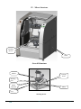
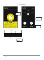
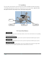
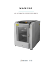
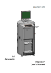
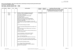
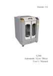
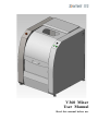
V360 Mixer User Manual Read this manual before use © 2008 Copyright Paint Mixing Machine. All rights reserved. Printed in the People’s Republic of China. Disclaimer No part of this book shall be reproduced, stored in retrieval, or transmitted by any means, electronic, mechanical, photocopying, recording, or otherwise without written permission of ZHENGZHOU SANHUA TECHNOLOGY & INDUSTRY CO.,LTD.. While every precaution has been taken in the preparation of this book, the publisher assumes no responsibility for errors or omissions. Neither is any liability assumed for damages resulting from the use of information contained herein. This document is the proprietary information of ZHENGZHOU SANHUA TECHNOLOGY & INDUSTRY CO., LTD., furnished for customer use only. No other uses are authorized without written permission of ZHENGZHOU SANHUA TECHNOLOGY & INDUSTRY CO., LTD. ZHENGZHOU SANHUA TECHNOLOGY & INDUSTRY CO., LTD. reserves the right to make changes without notice to this document and its products This manual contains information that is correct to the best of ZHENGZHOU SANHUA TECHNOLOGY & INDUSTRY CO., LTD.’s knowledge. It is intended to be a guide and should not be considered as a sole source of technique instruction, should not replace good technique judgment, since all possible situations cannot be anticipated. If there is any doubt about exact installation, configuration, and/or use, call ZHENGZHOU SANHUA TECHNOLOGY & INDUSTRY CO., LTD. The choice of system components is buyer’s responsibility; ZHENGZHOU SANHUA TECHNOLOGY & INDUSTRY CO., LTD. holds no liability for their use. However, ZHENGZHOU SANHUA TECHNOLOGY & INDUSTRY CO., LTD.’s sales team and application engineers are always available to assist you in making your decision. I Contents I. Introduction ……………………………………………………………………………………………1 II. Technical Specifications ………………………………………………………………………………1 III. Safety Instructions ……………………………………………………………………………………1 IV. Mixer Structure ……………………………………………………………………………………… 2 V. Control Panel ………………………………………………………………… …………………… 4 VI. Installation …………………………………………………………………………………………..5 VII. Control Panel Buttons ……………………………………………………………………………5 VIII. Operation …………………………………………………………………………………………6 I X . Wa r n in g s … … … … … … … … … … … … … … … … … … … … … … … … … … … … … … … … … … 7 X . Ma in ten a n c e … … … … … … … … … … … … … … … … … … … … … … … … … … … … … … … … … 7 XI. Troubleshooting ……………………………………………………………………………………7 XII. Tools …………………………………………………………………………………………………8 XIII. Nameplate ………………………………………………………………………………………… 9 XIV. Circuit Diagram ……………………………………………………………………………………10 II I. Introduction V360 Manual Clamping Mixer is designed for paint mixing. Main features include: Ergonomic design and clear viewing door facilitate observation of mixing process. Viewing door with electronic lock to protect the mixer from starting up while the door is open and to stop the door from being opened during operation. Manual clamping structure is compact, simple to operate and a low issue rate. An Electronic magnet ensures a safeguard for the mixer and paint container. Rotary door is convenient and reliable. The pulling-out lower tray makes locating the can a snap. II. Technical Specifications Power supply:See the nameplate Power:0.75kw Mixing Speed:125-175r/min Distance between upper and bottom plate:70mm~400 mm Paint can volume compatibility:1L~20 L Applicable cans:MAX Diameter: 30~275mm,Height: 70~400mm Dimension(Length X Width X Height) : 880 mm X760 mm X1080 mm Net Weight:170kg Noise:<70dB(A) Mixing Time:See the Mixing Time Table III. Safety Instructions Warning Labels: Danger of Electric Shock! Power source must be cut off before any cleaning or maintenance. Important information! Read it carefully. Power supply:see nameplate. Environment temperature:5ºC~50ºC,Relative humidity: 15%~90%; Read this manual carefully before installing and using the mixer. Do not let children or unauthorized personnel operate the mixer. Before carrying out any repairs or maintenance, unplug mixer from power source. It is strictly prohibited to perform repairs or maintenance before disconnecting the mixer or while it is in operation. Do not use an improper extension cable. Please disconnect the mixer when not in use for an extended period of time. Before use, please adjust the four feet to level the mixer securely to the ground. Wait 5s after mixer has stopped before opening the door. Do not open the door during mixing. V360 V1.0 -1- IV. Mixer Structure Working Device Shell Overall Structure Bucket Locking Parts Working Part Shock Absorber Motor Feet Working Device V360 V1.0 -2- Stop Dog Clamping Handle Fixed Mount Upper Platen Lower Platen Guide Axle Rotary Bucket Unit Guide Shaft Washer Spring Polyurethane Pad Spring Base Shock Absorber Unit V360 V1.0 -3- V. Control Panel Emergency Stop Button Tri-position knob Operation Button Mixing Time Table Knob Position 1-5L 6-10L 11-20L Medium and Light Color 3 min 2 min 2 min Dark Color 5 min 4 min 4 min Operation Button V360 V1.0 -4- VI. Installation For your safety and convenience, the mixer has been carefully assembled and tested at the factory. Cut bindings and unpack the wooden crate. Adjust the feet to level the machine. Open the front door panel and remove the transport screw and transport fixing mount. Feet Short Screw Long Screw Fixing Mount VII. Control Panel Buttons Tri-position Knob Put the can(s) on the center of the tray and clamp it (them), close the door, turn the knob to the corresponding volume position with the cans. Medium and light color button Press down the corresponding button as per the color of paint to be dispensed, the machine begins to operate. Dark color button Press down the corresponding button as per the color of paint to be dispensed, the machine begins to operate. Emergency stop button Press down the emergency stop button if there is any issue. The machine will cut off the power supply. When restarting the mixer, the emergency stop button needs be rotated clockwise to be reset it. V360 V1.0 -5- VIII. 1) Operation Open the equipment door, connect the power, turn on the power switch, press down the locking button, lift the upper plate unit to the top of guide shaft, and rotate the pressing handle to the position of Figure A. Upper Plate Unit Handle Guide Axle Lower Plate Unit Lower Tray Figure A 2) Pull out the tray. Position the sealed paint can in the center of the lower tray. Push back the tray. Press down the upper plate unit and clamp the paint can (use the binding band to fix the can handle). Rotate and clamp the handle to the position shown in Figure B. 3) Close the machine door. Choose the mixing time. 4) Press down the emergency stop button if there is any issue. Clamp Handle Lock Hook Figure B V360 V1.0 -6- 5) Open the door after the mixing is finished and the inner assembly has stopped spinning by lifting the door. Rotate the can unit to lock it. Release the clamp handle and slide the upper plate unit to the top of the guide axle. Push the lock hood upwards. Pull out the tray after unlocking is done and remove the can(s). 6) Disconnect the power supply when the machine is not used for extended periods of time. It takes 10s after powering on the mixer for it to be ready for mixing. IX. Warnings 1) Make sure the can lid is sealed well. 2) If there is any issue during the operation, press down the emergency stop button. Restart the machine after solving the problem. 3) Do not use deformed cans in the mixer. 4) Place the can(s) in the center of the lower tray. 5) If the working parts cannot operate or the rotation speed is too low, press the emergency stop button. 6) Only authorized personnel are allowed to dismantle and/or debug the machine. 7) Do not place anything on the door. X. Maintenance 8) Perform daily maintenance to ensure good condition of the machine. Disconnect the power supply prior to any maintenance (Only authorized personnel are allowed to dismantle the machine). 1) Keep the inside of the mixer clean. 2) Keep the upper plate guide axle clean. Lubricate the guide axle once in a month. 3) Lubricate the guide axle inside the shock absorber unit with lithium grease once in 6 months. 4) Open the back cover and check the tension of the belt once in a year. XI. Troubleshooting Troubles Causes 1. No power. Solutions Check the socket and the plug. 2. Emergency stop switch Disengage the emergency stop switch. Motor does not operate after engaged. starting. 3. Fuse or power line is Replace the fuse or power line. broken. V360 V1.0 -7- 4. Door is not in the correct position. Adjust the door position to make contact with the door. 5. Motor damaged. Replace the motor. 6. Broken belt. Change it. 7. Loose belt. Tension the belt properly. Motor doesn’t work 8. Over voltage or insufficient Install a voltage stabilizer. Instable mixing voltage. 9. Electromagnet damaged. Replace the electromagnet. 10. Locking pin is seized. Adjust the locking pin. 11. Return spring is broken. Replace the return spring. 12. Mixer is not leveled. Adjust the feet to level the mixer. Locking device does not operate. Extreme noise and/or 13. The cans are not centered or Change the position of the can. vibration. even. 14. Overloading. Decrease the loading. Contact your agent if there are any other issues. XII. Tools Name & Specifications Unit Quantity Binding band of can handle piece 1 piece 1 piece 1 12-14 open wrench piece 1 13-16 open wrench piece 1 8-10 open wrench piece 1 4 mm allen wrench piece 1 5 mm allen wrench piece 1 Protective tube 5A piece 1 Protective tube 12A piece 1 Philips driver medium Flat tip screwdriver small V360 V1.0 Remarks -8- XIII. V360 Nameplate V1.0 -9- XIV. V360 Circuit Diagram V1.0 - 10 - Zhengzhou Sanhua Technology & Industry Co., Ltd. Address:Xushui Industrial & Trading Park, Zhongyuan West Road, Zhongyuan Distric, Zhengzhou City, Henan Province, P.R. China, 450042 Tel:0371-67857220 After-service:0371-67857319 Fax:0371-67857166 Website:http://www.santint.com E-mail:[email protected]