1
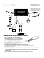
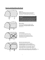
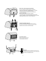
7 " W i d e LCD M o n i t o r
W i t h 4 M o u n t in g O p t i o n s
PLVH7IP
INSTRUCTION MANUAL
www.pyleaduio.com
Table of Contents
About the liquid crystal display (LCD) panel
2
Precautions
3
Control & Layout for monitor / wireless remote
4
Accessories
5
Connection diagram
6
Replacing the remote control battery
6
Installing headrest with shroud
7-8
Installing sun-visor with shroud
9-10
Installing of headrest case
11
Function Setting
12-18
Troubleshooting guide
18
Specifications
19
1
About the liquid crystal display (LCD) panel
1. Do not press on the LCD panel on the monitor unit as doing so can distort the picture or cause a
malfunction, the picture may become unclear, or the LCD panel may be damaged.
2. Notes on cleaning
-clean the LCD panel with a slightly damp soft cloth.
- do not use solvents such benzine, thinner, commercially available cleaners or antistatic spray.
3. Do not use this unit temperatures under 5 o C (41 o F) or over 45 oC (113 oF).
4. If your car was parked in a clod or hot place, the picture may not be clear. The monitor is not damaged.
The picture will become clear after temperature in your car becomes normal.
5.Some stationary blue or red dots may appear on the monitor. These are called bright spots, and happen
with any LCD.The LCD panel is highly sophisticated, and more then 99.99% of the segments used in
the panel are flawless. However, there is a possibility that less than 0.01% of the segments are defective
and may not light up properly. However, these segments will not interfere with your viewing.
Safety
To avoid the risk of accident and the potential violation of applicable laws, the fronts tv should
Never used while the vehicle is being driven. Also, rear displays should not be location where
It is a visible distraction to the driver.
In some countries the viewing of image on a display inside a vehicle even by persons other than
The driver may be illegal. Where such regulations, they must be obeyed and this unit’s features
Should not be used.
Warning
To Prevent fire or shock hazard, do not expose the unit to
rain or moisture.
CAUTION!!
RISK OF ELECTRIC SHOCK
DO NOT OPEN
!
Caution: To reduce the risk of electric shock
Do not remove cover (or Back)
No user-serviceable parts inside
Refer servicing to qualified service personnel
This symbol is intended to alert the user to
the presence of uninsulated “DANGEROUS
VOLTAGE” within the product’s enclosure
that may be of sufficient magnitude to
constitute a risk of electric shock to persons.
!
This symbol is intended to alert the user to
the presence of important operating and
maintenance(servicing) instructions in the
literature accompanying the appliance.
Disposal of old electrical & electronic equipment
( applicable in the European Union & other European
countries with separate collection systems)
This symbol on the product or on its packaging indicates that this product shall not be treated
as household waste. In stead it shall be handed over to the applicable collection point for the
recycling of electrical and electronic equipment. By ensuring this product is disposed of
correctly, you will help prevent potential negative consequences for the environment and
human health, which could otherwise be caused by inappropriate waste handling of this
product. The recycling of materials will help to conserve natural resources. For more detailed
information about recycling of this product, please contact your local Civic Office, your
household waste disposal service or the shop where you purchased the product
2
Precautions
Please read this manual completely and carefully prior to attempt to install your new car video
equipment. Install correctly, your new equipment will provide you with years of enjoyable and safe usage.
Installing this unit requires technical expertise. This unit should be installed by a qualified
technician or service personnel. If you try to install this unit by yourself, do it properly, referring to the
installation and wiring diagrams in this operating manual. Improper installation may result in fire or
electric shock.
1.Do not operate this equipment while driving-safe driving should always be your highest priority.
2.Do not install components in areas which are susceptible to rain, moisture direct sunlight, extremely
heat or cold, excessive dust, dirt or humidity.
3. Immediately unplug the power cord and send the monitor to your local dealer or service center as
soon as possible:
a) If there is smoke or any peculiar odor present during used
b) If there is damage to any of the internal components
4. To avoid damage to the monitor and risk of electronic shock, do not permit any of this equipment to
become damp or wet from water or liquid. If this does occur, immediately unplug the power cord and
send the monitor to your local dealer or service center as soon as possible.
5. Do not attempt to repair, open or disassemble any of the components. Dangerous high voltages are
present which may result in electric shock.
6. Use only a power source with DC12 volts car battery (negative ground).
7. Do not place or suspend objects on the power cord, as this may damage the cord.
8. Do not twist or place the power cord near any source of heat in the vehicle.
9. Do not attempt to repair a damaged, broken or faulty power cord. Replace it with a new one immediately.
10. Avoid dropping any metal objects or inflammable items into the monitor ventilation slots.
11. After the monitor is installed, do not arbitrarily pull it down or strike it. This may loose the mounting
screws and cause it fall down.
12. Do not install this unit where:
a) it will obstruct the driver’s view.
b) it will obstruct the operation of the airbag system.
c) it will obstruct the operation of the vehicle, especially the steering wheel, shift lever, or brake pedal.
d) a diver or passengers may injure themselves when getting into or out of the car.
3
Control and layout for the monitor
Front Audio Output
Front audio output
(headphones)
Blue screen when
no video signal
MMI Input
Front audio video input
(Plug & Play for Ps2 or games)
Remote Sensor
Remote control IR sensor
Power On / Off
Turn on/off the monitor
Front A/V Input
Front audio video input
Menu
Press to display MENU
with functions and setting
Power Cord
(Male)
Adjust Increase
This multipurpose button
serves to increase the selected
parameters, such as volume,
contrast etc.
Adjust Decrease
This multipurpose button serves
to decrease the selected
parameters, such as volume,
contrast etc.
Notice: some functions are work by remote control.
Control and layout for the remote control
Mute
Press to Mute the sound, press again
to restore the previous volume level
Power On/Off
Turn On / Off the monitor
Volume Increase
Adjust increase headphone output
volume
Ad just Increase
This mu ltipurpose bu tton se rves to
adjust down to se lect me nu function
an d increase the se lected parame ters
su ch as co ntrast, color, brightness etc
Adjust Decrease
This multipurpose button serves to
adjust up to select menu function
and decrease the selected parameters
such as contrast, color, brightness etc.
Volume Reduce
Adjust reduce headphone output
volume
Preset
Picture preset by factory
Menu
This button brings up the on-screen
menu for adjustment of a range of
monitor parameters such as,
vol, con, col, bri, tint. Etc
V1/V2
Select Video 1 or Video 2 Input
Invert
To adjust the picture
up/down/left/right
When you use a wireless radio or portable telephone near
this unit, picture or sound interference may occur. Do not
use such devices near this unit.
4
Accessories
Universal Stand
Headrest &
Sun Visor Shroud
Headrest Bag
Remote Control
Extension Min Din Cable
Key-for removing the monitor
from headrest or visor shroud
AV Cable
INSTRUCTION MANUAL
Earphone
Instruction Manual
5
Fuse replacement
Never use fuse with an amperage rating
exceeding the one supplied with the unit as
this could damage the unit.
Connection Diagram
E a rp
When replacing the fuse, be sure to use one
that matches the amperage described on the
original fuse. If the fuse blows, check the
power connection and replace the fuse. If the
fuse blows again after replacement, there may
be an internal malfunction. In such a case,
consult your nearest your’s dealer.
Blue screen when
no video signal
hone
1
Fuse
(2A)
LL
YE
Games
Audio Input (Red RCA)
Video Input (Yellow RCA)
RED
BL
AC
K
R ED
OW
YELLOW
Audio Input (Red RCA)
Video Input (Yellow RCA)
RED
2
BATTERY
Video
Player
Replacing the Remote Control Batter y
1 )Alwa ys use ne w battery when rep lace the o ld se t.
2 )Do not attempt to charge , short-circuit, disassemble,
heat or burn used batteries, b attery ma y b e explode
if mistreate d.
PULL OUT
3 )B attery re place ment is necessa ry whe n remote
PUSH IN
con trol acts sporadically or stops operatin g.
4)Do not drop, apply sh ock or step on the remote con trol.
5)Do not spill wate r on the remote contro l.
6)Do not place objects betwe en the remote contro l and remo te sensor.
7)Do not use remote con trol fo r the othe r equipments at the same time.
8)Do not lea ve the remote near an y h eat sou rces, o r in a p la ce sub je ct to dire ct su nlig ht
(especially o n th e dashboa rd).
9) K eep the lith iu m battery out of the re ach of children. Sho uld th e battery be swallowed, imme diately
consult a doctor.
10)If the MO NITO R does not opera te even wh en you o perate the remote co ntrol from a close range,
it is time to rep la ce the b attery (u se CR-20 25 lithium b attery), refer ring to the la bel on the b ack of
th e basic con trol.
11)Do n ot h old th e battery with metallic twe eze rs, othe rwise a sho rt-circuit may occur.
6
Steps For Installing Headrest with Shroud
Setup work
Remove the headrest and set it in an uncluttered
work area. Pay the appropriate precautions to
ensure that it is not damaged during the installation.
CAUTION: make sure the screws are not long enough to go through
the headrest!
If you have any doubtsabout this typeof installation, please consult
your local mobile electronics retailer. Cutting and making holes in
the headrest will causeelectronic damage which is expensive to repair.
Measurements
Press the headrest with your fingers to make
sure there are no obstructions that would hinder
the installation. Use paper template to mark the
area to be cut.
Cut the headrest
Use an adjustable-depth blade, start
your cut 1/4 inch inside one corner and
cut diagonally across, stopping 1/4 inch in
from the other corner. Repeat this procedure
for the other two corners.
Re move foam & obs tructions
Ca re fully peel off the material. Set the
a djustable b lad e to one in ch depth and cut
a round the e dges of the hole, staying 1/4 inch
inside the e dge. Pull up one corner of the foam
a nd use the b la de to cut un derneath. Re move
small section at a time and e nsu re to be the
u niform de pth. Use a dreme l or oth er appro pria te
tools to remo ve other obstructions. Insert the monitor to
me asure the fit and make a djustment if necessa ry
7
Route the cable through the headre st
Run the su pplied cable through the opening
a nd ou t to the bottom of the headre st. If possib le ,
conceal the wires with a sh aft covering.
Con nect the power, g round a nd video lea ds to
test the MO NITOR.
B efore co nnecting the mon itor, pull the
conn ectin g cable th ro ugh the h eadrest shroud as
shown in diagram. Place th e hea drest hou sing into the
o pening a nd secure with correct fa steners.
Install the headrest shroud
Pull the connecting ca ble th ro ugh the center of
the sh roud as shown in diagram, and secure the
head re st sh roud with co rre ct fasten ers
Insert the monitor
Push to insert the monitor
to the headrest shroud.
Removal
Insert the release key between the monitor and
headrest shroud gap and pull it out to remove the
monitor from headrest shroud.
8
Steps For Installing Sun-visor with Shroud
Setup work
Remove the visor and set it in an uncluttered
work area. Pay appropriate precautions to
ensure that it is not damaged during the installation.
CAUTION: make surethe screws are not long enoughto go through
the visor!
If youhave any doubts about this type of installation, please consult
yourlocal mobile electronics retailer. Cutting and making holes in
the visor will cause electronic damage which is expensive to repair.
Measurements
Press push on the headliner with your fingers to make
sure there are no obstructions that would hinder
the installation. Use paper template to mark the
area to be cut.
Cut the visor
Use an adjustable-depth blade, start
your cut 1/4 inch inside one corner and
cut diagonally across, stopping 1/4 inch in
from the other corner. Repeat this procedure
for the other two corners.
Rem ov e foam & obstruc tions
Carefully pe el off the material. S et the
ad ju stable blade to one inch d epth and cut
arou nd the ed ges of the hole, sta ying 1/4 in ch
inside the edg e. P ull up o ne corner of th e fo am
an d use the blade to cut und erneath. Remove
small se ction at a time, ensure to be the
un iform depth . Use a dreme l or oth er appro pria te
tools to remo ve other obstructions. Inse rt the
monitor to measure th e fit and make
adjustme nt if necessary.
9
Route the cable through the visor
Run the sup plie d cable th rough the o pening
an d out to the bottom of the visor. If possible,
conceal the wires using a shaft coverin g.
Conn ect th e power, gro und an d vid eo lead s to
test th e MONITOR. Befo re co nnecting the
monitor, pull th e co nnecting cable assembly
through the visor housing a s shown in diagram.
Place sun-visor shrou d into the opening and
secure it with co rre ct faste ners.
Ins ta ll the sun-visor shroud
P ull the conn ecting cable through the cen ter o f
the ho using as sh own in diagra m, and secure
the sun-visor shroud with correct fa steners
Insert the monitor
Push to insert the monitor
to the sun-visor shroud.
Removal
Insert the release key between the monitor and
visor shroud gap and pull it out to remove the
monitor from headrest shroud.
Oper ate your syst em in a saf e and legal manner
When oper ate a motor vehi cle, it shoul d always be your highest priority to
maintain saf e driving habi ts.
It is illegal in many areas of most count ries to drive with TV or MONITOR
on, when it is visible to the driver. Please check your local and st ate
laws gover ning the use of MOBILE ENTER TAINMENT SYSTE M in your area.
10
Steps For Installing Headrest Bag
Insert the monitor to the headrest bag
Put the monitor with headrest bag at the
rear side center of pillow.
Rear side of headrest
Cut the magic tape to the fit your pillow size,
then fasten it as X as diagram show.
Front side of headrest
11
Function setting
SOURCE
Press MENU button (1)from the remote or press
manu button (1) from the monitor to call out the
function menu, press button (2 or 3) to the
desired setting.
AV1
AV2
AV3
RETURN
2
1
3
Monitor
Remote
SOURCE
When screen appears “SOURCE” Press Menu
button (1) to enter video signal input selection.
[ The
symbol show current video input. ]
AV1
AV2
AV3
RETURN
2
1
3
Monitor
Remote
SOURCE
Press the button( 2or3) to move the
symbol
and choose video signal input.
Press menu button (1) to confirm your selection.
Move the
symbol to RETURN and press
menu button (1) to exit input setting.
AV1
AV2
AV3
RETURN
2
1
3
Remote
12
Monitor
PICTURE
When screen appears “PICTURE” press the menu
button (1)to enter picture parameters setting.
BRIGHT
CONTRAST
COLOR
RETURN
2
1
3
Monitor
Remote
PICTURE
Press the button( 2or3) to adjust the
symbol
to choose “BRIGHT”.
Press menu button (1) to enter BRIGHT setting.
[ Brightness: Makes black appear darker or lighter ]
BRIGHT
CONTRAST
COLOR
RETURN
2
1
3
Monitor
Remote
PICTURE
Press button 2: adjust brightness to lighter level.
Press button 3: adjust brightness to darker level.
Press button 1 to confirm setting.
[Brightness adjustable level: 0~100 . Preset: 50]
2
1
BRIGHT 50
3
Remote
13
Monitor
PICTURE
Press the button( 2or3) to adjust the
symbol
to choose “CONTRAST”.
Press menu button (1) to enter CONTRAST setting.
[ Contrast: Narrows or widens the gap between black & white
(darken & brighten)]
BRIGHT
CONTRAST
COLOR
RETURN
2
1
3
Monitor
Remote
PICTURE
Press button 2: adjust contrast to brighter level.
Press button 3: adjust contrast to darker level.
Press button 1 to confirm setting.
[Contrast adjustable level: 0~100 . Preset: 50]
2
1
CONTRAST 50
3
Monitor
Remote
PICTURE
Press the button( 2or3) to adjust the
symbol
to choose “COLOR”.
Press menu button (1) to enter hue setting.
[COLOR: adjusts more or less color intensity]
BRIGHT
CONTRAST
COLOR
RETURN
2
1
3
Remote
14
Monitor
PICTURE
Press button 2: adjust more color intensity level.
Press button 3: adjust less color intensity level.
Press button 1 to confirm setting and exit.
[Color adjustable level: 0~100 . Preset: 50]
2
1
COLOR 50
3
Monitor
Remote
PICTURE
Exit Picture setting, Press the button( 2or3) to
adjust the
symbol to “RETURN”.
Press menu button (1) to exit.
BRIGHT
CONTRAST
COLOR
RETURN
2
1
3
Monitor
Remote
AUDIO
When screen appears “PICTURE” press the menu
button (1)to enter picture parameters setting.
Press the button( 2or3) to adjust the
symbol
to choose “VOLUME”.
Press menu button (1) to enter volume setting.
VOLUME
RETURN
[VOLUME: adjust sound soft or loud ]
2
1
3
Remote
15
Monitor
AUDIO
Press button 2: adjust sound to more loud level.
Press button 3: adjust sound to more soft level.
Press button 1 to confirm setting and exit.
[Volume adjustable level: 0~100 . Preset: 50]
2
1
VOLUME 50
3
Monitor
Remote
FUNCTION
When screen appears “FUNCTION” press the menu
button (1)to enter function parameters setting.
Press the button( 2or3) to adjust the
symbol
to choose desired setting
INVERT 1
SIZE:
Full 16:9
Language Select:
RETURN
2
1
3
Monitor
Remote
FUNCTION
When the
symbol at “INVERT1” and Press the
MENU (1) button repeatedly to invert the picture,
each time the button press the picture rotate as
clockwise as the diagram show.
Inve rt 1
LCD
M ONITOR
INVERT 1
SIZE:
Full 16:9
Language Select:
RETURN
2
LCD
MONITOR
1
16
Inve rt3
3
Remote
Monitor
FUNCTION
Normal 4:3
Full 16:9
Diagram
Diagram
When the
symbol at “SIZE” Press the MENU (1)
button repeatedly to change the picture display
size to Full 16:9 or Normal 4:3 as the diagram show.
INVERT 1
SIZE:
Full 16:9
Language Select:
RETURN
2
1
3
Monitor
Remote
FUNCTION
When the
symbol at “Language Select:” Press
the MENU (1) button to enter the OSD languages
display.
INVERT 1
SIZE:
Full 16:9
Language Select:
RETURN
2
1
3
Monitor
Remote
FUNCTION
Press the buttons 2 or 3 to the desired language,
and press “MENU” to confirm.
English
German
French
Spanish
Portugal
Italian
Chinese C
RETURN
2
1
3
Remote
17
Monitor
FUNCTION
When the
symbol at “Exit” Press the MENU (1)
button to exit the setup.
Exit
2
1
3
Monitor
Remote
Troubleshooting guide
The following checklist will help you solve problems you may encounter with your unit.
Before going through the checklist below, check the connection and operating.
if you can not solve the problem with follows guide, please contact your nearest dealer.
Problem
Cause/solution
The power cord or battery has been disconnected.
The fuse has blown.
Press power on.
Press the volume increase button on the wireless
remote, or on the monitor.
Press the mute button from the wireless remote.
No picture, no sound
Good picture, but no sound
(TIP: refer to page 4 for the “control & layout”)
Dolled lines or stripes
This maybe caused by local interference such as car
engine or motorcycle.
No picture, or no sound when you
connect the optional equipment
The cord has been disconnected. Connect the cord
securely.
Press power on.
No response when pressing the buttons on
the wireless remote
The wireless remote batteries may be exhausted.
18
Specifications:
LCD Drive Method: a-SI TFT Active Matrix
Visible Screen Size: 7 Inch Wide Screen (Diagonal)
Aspect Ratio: 16:9
Display Format: 480 x RGB x 234
Number of Pixels: 336,960
Response Time: 15ms
Backlight : High Brightness CCFT
Luminance: 380 cd/m 2 #3
Backlight Life: 15,000 Hrs #1
Contrast Ratio: 300:1
Viewing Angle: (H/V): 120 o / 100 o
o
o
o
o
Operation Temperature: -20 C ~ 70 C / -2 F ~ 158 F
Video Color System Input: NTSC & PAL Compatible
On Screen Display: Multi Languages
(English, German, French, Spanish, Portugal, Italian, Chinese)
Rear Video Input Terminals: RCA x 1 (1 Vp-p, 75 ohm)
Front Video Input Terminals: 3.5mm Jack x1 (1 Vp-p, 75 ohm)
Front Audio Input Terminals: 3.5mm Jack x1 (-10 dBs, 10 Kohm)
Front Audio Output Terminals: 3.5mm Jack x1 (-10 dBs, 10 Kohm)
Front Video Input Terminals: MMI Plug
Front Audio Input Terminals: MMI Plug
Remote Control: Included
Volume / Brightness / Contrast / Color: Adjustable
Blue Screen: Yes
Power Input: DC12 Volts car battery (negative earth)
Current Consumption: 6 W Max
Weight: 340 g / 0.75 Lbs
Size: 186 x 105 x 22.5 cm (W x H x D)
7.32 x 4.13 x0. 88 inch (W x H x D)
#1
A measure of the time unit screen brightness declines by half under continuous viewing
in a car/room at 25 oC with screen brightness in standard mode. (50% original brightness)
#2
A measure of the unit temperature declines in a car/room at 25 oC
with screen brightness in standard mode. (50% original brightness)
#3
A measure of the backlight 350cd/m brightness will in standard
lamp voltage at 560 Vrms.
2
Pyle, Inc.
rd
1600 63 street
Brooklyn, NY 11204
0
19
6 88 88 8 83 59
7