1
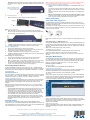
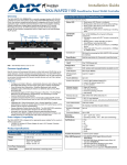
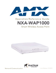
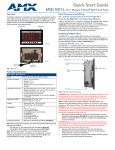
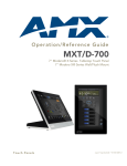
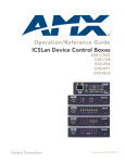
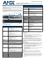
Installation Guide
NXA-ENET8-2POE Gigabit Ethernet Layer 2 PoE Switch
Overview
NXA-ENET8-2POE Hardware Specifications (Cont.)
The NXA-ENET8-2POE (FG2178-63) is a Gigabit Ethernet Layer 2 PoE switch with 8 10/
100/1000BASE-T ports, and 2 Small Form Factor Pluggable (SFP) transceiver slots, (see
Figure 1, Ports 9-10).
The NXA-ENET8-2POE also includes an SNMP-based management agent, which provides
in-band access for managing the switch.
The NXA-ENET8-2POE provides a broad range of powerful features for Layer 2 switching,
delivering reliability and consistent performance for your network traffic. They bring order to
poorly performing networks by segregating them into separate broadcast domains with IEEE
802.1Q compliant VLANs, and empower multimedia applications with multicast switching
and CoS services.
Power Requirements:
1000BASE-T/SFP Ports (9-10)
SPF Port Status LEDs (ports 9-10 Link/Activity/Speed)
PoE Status LEDs (ports 1 - 8)
Power Status LED
Power Consumption
• 75 Watts for PoE power (Max from AC inlet)
• 20 Watts for system power
Voltage:
• 100-240V
• 50-60Hz
• 1.5 A
Current:
• 1.5 A @ 110 VAC
• 0.75 A @ 220 VAC
Power Supply
• AC Power: 100 to 240 V, 50-60 Hz, 0.7A
• Power Supply: Internal, auto-ranging transformer:
100 to 240 VAC, 50 to 60 Hz
• Power Consumption: 100 Watts
• Maximum Current: 1.7A @ 100 VAC
10/100/1000 Mbps
RJ45 PoE Ports (1-8)
Physical
Reset Button
Diagnostics Status LED
Ethernet Port Status LEDs (ports 1-8)
(Link/Activity/Speed)
Grounding Point
Power Inlet
Size (W x D x H)
33 x 20.4 x 4.3 cm (12.99 x 8.03 x 1.69 in.)
Weight
2.2 kg (4.85 lbs)
Environmental
Temperature:
• Standard Operating: 0°C to 50°C (32°F to 122°F)
• Non-Operating (Storage): -40°C to 70°C (-40°F to 158°F)
Humidity
10% to 90% (non-condensing)
Compliances
•
•
•
•
•
•
W FCC Part 15 Class A
IC CISPR 22 Class A
CE EN 55022 Class A and EN 55024
LVD EN 60950-1
CB Scheme IEC 60950-1
CSA 22.2 NO 60950-1
Included Accessories
•
•
•
•
Four adhesive foot pads
Grounding screw
Two brackets and eight screws
Power Cord
FIG. 1 NXA-ENET8-2POE (front and rear panels)
Hardware Specifications
NXA-ENET8-2POE Hardware Specifications
Features
•
•
•
•
•
•
IGMP snooping v1/v2/v3
IPv6 support
802.1Q VLAN support
802.1X Port and MAC-based authentication
IEEE 802.1p CoS support
In-band Management: Web, or SNMP manager
•
•
•
•
•
•
•
Switching Capability: 20 Gbps (aggregate bandwidth)
Packet Buffer Size: 1 MB
Switching Database: 8K MAC Address Table
Flash: 8 MB
Forwarding Mode: Store-and-forward
Throughput: Wire speed
Flow Control: Full Duplex: IEEE 802.3x, Half Duplex: Back
pressure
Standards
•
•
•
•
•
•
IEEE 802.3-2005
Ethernet, Fast Ethernet, Gigabit Ethernet
Full-duplex flow control
Link Aggregation Control Protocol
IEEE802.3at Power-over-Ethernet
ISO/IEC 8802-3
Physical Ports:
• 8 10/100/1000BASE-T RJ-45 PoE ports
• 2 Gigabit Ethernet SFP slots (dual speed 100/1000BASE-X)
LEDs
• System: PWR, DIAG, PoE
• Port: Status (Link, Speed, Activity)
Performance
Network Interface
Ports 1-8:
RJ-45 connector, auto MDI/MDI-X:
• 10BASE-T: RJ-45 (100-ohm, UTP cable; Cat 3 or better)
• 100BASE-TX: RJ-45 (100-ohm, UTP cable; Cat 5 or better)
• 1000BASE-T: RJ-45 (100-ohm, UTP cable; Cat 5, 5e or better)
Maximum cable length - 100 m (328 ft)
Ports 9-10:
SFP transceiver slots:
100BASE-FX, 1000BASE-SX,1000BASE-LX, 1000BASE-LH,
1000BASE-T
The maximum length for fiber optic cable operating at Gigabit
speed will depend on the fiber type.
See the 1000 MBPS Gigabit Ethernet Collision Domain section in
the NXA-ENET8-2POE Operation/Reference Guide for details.
PoE (IEEE 802.3at Power over Ethernet)
Max output power:
Up to 30 W per port, within the total PoE power budget
Total PoE budget:
75 W
Voltage:
Maximum current: 1.7A
PoE Output Voltage:
48 V DC
Other AMX Equipment: • NXA-WAP1000 - 802.11a/b/g/n Wireless Access Point
(FG2255-51/53)
• NXA-WAPZD1100 - Wireless LAN ZoneDirector (FG2255-75,
FG2255-54K – 60K)
Installation
Selecting a Site
The site should:
• Be at the center of all the devices you want to link and near a power outlet.
• Be able to maintain its temperature within 0° to 50°C (32° to 122°F) and its humidity
within 10% to 90%, non-condensing
• Provide adequate space (approximately two inches) on all sides for proper air flow
• Be accessible for installing, cabling and maintaining the devices
• Allow the status LEDs to be clearly visible
Make sure twisted-pair cable is always routed away from power lines, fluorescent lighting
fixtures and other sources of electrical interference, such as radios and transmitters.
Make sure that the unit is connected to a separate grounded power outlet that provides 100
to 240 VAC, 50 to 60 Hz, is within 2 m (6.6 feet) of each device and is powered from an
independent circuit breaker. As with any equipment, using a filter or surge suppressor is
recommended.
Ethernet Cabling
To ensure proper operation when installing the NXA-ENET8-2POE into a network, make sure
that the current cables are suitable for 10BASE-T, 100BASE-TX, or 1000BASE-T operation.
Check the following criteria against the current installation of your network:
• Cable type: Un-shielded twisted pair (UTP) or shielded twisted pair (STP) cables with
RJ-45 connectors; Category 3 or better for 10BASE-T, Category 5 or better for
100BASE-TX, and Category 5, 5e, or 6 for 1000BASE-T.
• Protection from radio frequency interference emissions
• Electrical surge suppression
• Separation of electrical wires (switch related or other) and electromagnetic fields from
data based network wiring
• Safe connections with no damaged cables, connectors or shields
Mounting
The NXA-ENET8-2POE can be mounted in a standard 19-inch equipment rack or on a
desktop or shelf. Mounting instructions for each type of site follow (see reverse).
Rack Mounting
Before rack mounting the NXA-ENET8-2POE, pay particular attention to the following
factors:
• Temperature: Check that the rack environment temperature (within a rack assembly)
is within the specified operating temperature range (see the Specifications table).
• Mechanical Loading: Do not place any equipment on top of the rack-mounted unit.
• Circuit Overloading: Be sure that the supply circuit to the rack assembly is not overloaded.
•
Grounding: Rack-mounted equipment should be properly grounded. Particular attention should be given to supply connections other than direct connections to the mains
(FIG. 2).
Note: Do not plug a phone jack connector into an RJ-45 port. This will damage the switch.
Use only twisted-pair cables with RJ-45 connectors that conform to FCC standards.
Connecting to PCs, Servers, Hubs and Switches
1.
Attach an insulated grounding
wire with a metal screw, to the
marked Grounding Point
2.
Terminate the wire in an earthed grounding point
3.
FIG. 2 Grounding
1.
Attach the brackets to the device using the screws provided (FIG. 3):
Connect one end of a twisted-pair cable segment to the NXA-ENET8-2POE’s RJ-45
connector.
If the device is a network card and the switches are in the wiring closet, connect the
other end of the cable segment to a modular wall outlet that is connected to the wiring
closet.
Otherwise, connect the other end of the cable segment directly to an available port on
the switch.
Make sure each twisted pair cable does not exceed 100 meters (328 ft) in length.
As each connection is made, the Link LED (on the switch) corresponding to each port
will turn on (green or amber) to indicate that the connection is valid.
Cables and Pinouts
Twisted-Pair Cable Assignments
FIG. 3 Attaching the Brackets
2.
For 10/100BASE-TX connections, a twisted-pair cable must have two pairs of wires. For
1000BASE-T connections the twisted-pair cable must have four pairs of wires. Each wire pair
is identified by two different colors.
For example, one wire might be green and the other, green with white stripes. Also, an RJ-45
connector must be attached to both ends of the cable. FIG. 5 illustrates how the pins on the
RJ-45 connector are numbered.
Mount the device in the rack, using four rack-mounting screws (not provided).
Be sure to secure the lower rack-mounting screws first to prevent the brackets being
bent by the weight of the switch (FIG. 4):
FIG. 5 RJ-45 Connector
Note: Be sure to hold the connectors in the same orientation when attaching the wires to the
pins.
FIG. 4 Installing the NXA-ENET8-2POE in a Rack
3.
4.
If installing a single switch only, refer to the Connecting To a Power Source section.
If installing multiple switches, mount them in the rack, one below the other.
Desktop or Shelf Mounting
1.
2.
3.
4.
Attach the four adhesive feet to the bottom of the first switch.
Set the device on a flat surface near an AC power source, making sure there are at
least two inches of space on all sides for proper air flow.
If installing a single switch only, see Connecting To a Power Source below.
If installing multiple switches, attach four adhesive feet to each one. Place each device
squarely on top of the one below.
Connecting To a Power Source
1.
2.
3.
Insert the power cable plug directly into the AC Power Inlet on the rear panel.
Plug the other end of the cable into a grounded, 3-pin, AC power source.
Note: For international use, you may need to change the AC line cord. You must use a
line cord set that has been approved for the wall socket type in your country.
Check the front-panel LEDs as the device is powered on to be sure the Power LED is
on green. If not, check that the power cable is correctly plugged in.
Connecting Network Devices
The NXA-ENET8-2POE is designed to be connected to 10, 100, or 1000 Mbps network
cards in PCs and servers, as well as to other switches and hubs. It may also be connected to
remote devices using optional 1000BASE-SX, 1000BASELX, 1000BASE-LH, or 100BASEFX SFP transceivers.
Twisted-Pair Devices
Each device requires an un-shielded twisted-pair (UTP) cable with RJ-45 connectors at both
ends. Use Category 5, 5e, or 6 cable for 1000BASE-T connections, Category 5 or better for
100BASE-TX connections, and Category 3 or better for 10BASE-T connections.
Power-Over Ethernet Connections
The NXA-ENET8-2POE automatically detects a PoE-compliant device by its authenticated
PoE signature and senses its required load before turning on DC power to the port. This
detection mechanism prevents damage to other network equipment that is not PoE
compliant.
Note: PoE connections work with all existing Category 3, 4, 5, 5e, or 6 network cabling,
including patch cables and patch-panels, outlets, and other connecting hardware, without
requiring modification.
• The NXA-ENET8-2POE delivers power to a device using the wire pairs in UTP or STP
cable (RJ-45 pins 1, 2, 3, and 6). The switch can provide up to 34.2 W of power
continuously on each of the eight RJ-45 ports. If a device tries to draw more than
34.2 W from a port, an overload condition occurs and the port disables the power.
• The NXA-ENET8-2POE controls the power and data on a port independently. Power
can be requested from a device that already has a data link to the switch.
• Also, the NXA-ENET8-2POE can supply power to a device even if the port’s data
connection has been disabled. The power on a port is continuously monitored by the
NXA-ENET8-2POE and it will be turned off as soon as a device connection is
removed.
Cabling Guidelines
The RJ-45 ports on the NXA-ENET8-2POE supports automatic MDI/MDI-X pinout
configuration, so you can use standard straight-through twisted-pair cables to connect to any
other network device (PCs, servers, switches, routers, or hubs). See the NXA-ENET8-2POE
Operation/Reference Guide for further information on cabling.
Auto-Negotiation / MDI-X Support
Auto-negotiation MDI/MDIX means that every port on the switch will automatically detect the
Ethernet cable type being used (straight-through or crossover) and adjust to make a link over
that cable. The NXA-ENET8-2POE supports MDI-X on all ports. Therefore either cable type
can be used.
Note: Follow TIA-568B straight-through cabling standards.
10/100BASE-TX Pin Assignments
Use un-shielded twisted-pair (UTP) or shielded twisted-pair (STP) cable for RJ-45
connections: 100-ohm Category 3 or better cable for 10 Mbps connections.
Note: Be sure that the length of any twisted-pair connection does not exceed 100 meters
(328 feet).
Using the Web Console
The NXA-ENET8-2POE provides an embedded HTTP web agent. Using a web browser you
can configure the switch and view statistics to monitor network activity. The Web Console
can be accessed by any computer on the network using a standard web browser (Internet
Explorer 5.0, Netscape 6.2, Mozilla Firefox 2.0.0.0, or more recent versions).
Default Login Information
Default IP Address
The default IP Address for the NXA-ENET8-2POE is: 192.168.1.10.
Default User Name and Password
To access the Web Console interface you must first enter a user name and password. The
administrator has Read/Write access to all configuration parameters and statistics.
The default User Name and Password for the administrator is “admin.”
Home Page
When your web browser connects with the switch’s web agent, the home page is displayed
as shown below. The home page displays the Main Menu on the left side of the screen and
an image of the front panel on the right side. The Main Menu links are used to navigate to
other menus, and display configuration parameters and statistics.
FIG. 6 Web Console - Home Page
Refer to the NXA-ENET8-2POE Operation/Reference Guide for instructions on using the
Web Console to configure the switch. The Operation/Reference Guide also provides detailed
and instructions on using the Web Console to monitor the switch as well as perform
diagnostics and maintenance.
Additional Documentation
Refer to the NXA-ENET8-2POE Operation/Reference Guide for additional installation and
cabling details (including fiber optic cable), as well as detailed Compliance and Safety
information.
For full warranty information, refer to the AMX Instruction Manual(s) associated with your Product(s).
6/12
©2012 AMX. All rights reserved. AMX and the AMX logo are registered trademarks of AMX.
AMX reserves the right to alter specifications without notice at any time.
3000 RESEARCH DRIVE, RICHARDSON, TX 75082 • 800.222.0193 • fax 469.624.7153 • technical support 800.932.6993 • www.amx.com
93-2178-63
REV: A