1
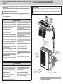
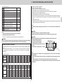
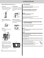
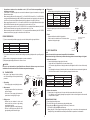
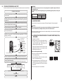
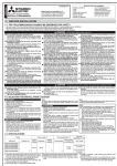
SPLIT-TYPE AIR CONDITIONER CONTENTS 1. THE FOLLOWING SHOULD ALWAYS BE OBSERVED FOR INSTALLATION MANUAL Model MXZ-3A54VA MXZ-4A71VA 2. INSTALLATION DIAGRAM & ACCESSORIES ..................................2 HFC 3. SELECTING THE INSTALLATION LOCATION .................................3 R410A 5. INDOOR/OUTDOOR UNITS CONNECTION FINISHING AND utilized Refer to the installation manual of each indoor unit for indoor unit installation. FOR INSTALLER SAFETY .............................................................................................2 4. OUTDOOR UNIT INSTALLATION .....................................................4 TEST RUN .........................................................................................5 IMPORTANT NOTES TO COMPLY WITH THE REQUIREMENTS OF AUSTRALIAN STANDARD AS 3000 S.A.A. WIRING RULES, THE ELECTRICAL WIRING REQUIRED BETWEEN THE INDOOR AND OUTDOOR UNITS MUST BE INSTALLED BY A LICENCED ELECTRICAL CONTRACTOR. 1. THE FOLLOWING SHOULD ALWAYS BE OBSERVED FOR SAFETY 2. INSTALLATION DIAGRAM & ACCESSORIES • Be sure to read “THE FOLLOWING SHOULD ALWAYS BE OBSERVED FOR SAFETY” before installing the air conditioner. • Be sure to observe the cautions specified here as they include important items related to safety. • The indications and meanings are as follows. Before installation This installation manual is only for the outdoor unit installation. In installing the indoor units, refer to the installation manual attached to each indoor unit. Any structural alternations necessary for the installation must comply with the local building code requirements. WARNING: Could lead to death, serious injury, etc. CAUTION: Could lead to serious injury in particular environments when operated incorrectly. • After reading this manual, be sure to keep it together with the OPERATING INSTRUCTIONS in a handy place on the customer’s site. WARNING Do not install the unit by yourself (customer). Incomplete installation could cause injury due to fire, electric shock, the unit falling or leakage of water. Consult the dealer from whom you purchased the unit or special installer. Install the unit securely in a place which can bear the weight of the unit. When installed in an insufficient strong place, the unit could fall causing injury. Use the specified wires to connect the indoor and outdoor units securely and attach the wires firmly to the terminal block connecting sections so the stress of the wires is not applied to the sections. Incomplete connecting and fixing could cause fire. Do not use intermediate connection of the power cord or the extension cord and do not connect many devices to one AC outlet. It could cause a fire or an electric shock due to defective contact, defective insulation, exceeding the permissible current, etc. Check that the refrigerant gas does not leak after installation has completed. If refrigerant gas leaks indoors, and comes into contact with the fire of a fan heater, space heater, stove, etc., harmful substances will be generated. Perform the installation securely referring to the installation manual. Incomplete installation could cause a personal injury due to fire, electric shock, the unit falling or leakage of water. Perform electrical work according to the installation manual and be sure to use an exclusive circuit. If the capacity of the power circuit is insufficient or there is insufficient electrical work, it could result in a fire or an electric shock. Attach the electrical cover to the indoor unit and the service panel to the outdoor unit securely. If the electrical cover in the indoor unit and/or the service panel in the outdoor unit are not attached securely, it could result in a fire or an electric shock due to dust water, etc. Be sure to use the part provided or specified parts for the installation work. The use of defective parts could cause an injury due to a fire, an electric shock, the unit falling, leakage of water, etc. Be sure to cut off the main power in case of setting up the indoor electronic control P.C. board or wiring works. It could cause an electric shock. The appliance shall be installed in accordance with national wiring regulations. When installing or relocating the unit, make sure that no substance other than the specified refrigerant (R410A) enters the refrigerant circuit. Any presence of foreign substance such as air can cause abnormal pressure rise or an explosion. D K H C I Open as a rule More than 500 mm if the front and both sides are open E J More than 100 mm More than 200 mm if there are obstacles to both sides More than 100 mm F CAUTION Perform earthing. Do not connect the earth wire to a gas pipe, water pipe, lightning rod or telephone earth wire. Defective earthing could cause an electric shock. Do not install the unit in a place where an inflammable gas leaks. If gas leaks and accumulates in the area surrounding the unit, it could cause an explosion. Fasten a flare nut with a torque wrench as specified in this manual. When fastened too tight, a flare nut may broken after a long period and cause a leakage of refrigerant. Install an earth leakage breaker depending on the installation place (Where it is humid). If an earth leakage breaker is not installed, it could cause an electric shock. Perform the drainage/piping work securely according to the installation manual. If there is a defect in the drainage/piping work, water could drop from the unit and household goods could be wet and damaged. Open as a rule More than 500 mm if the back, both sides and top are open 2 More than 350 mm Note: The dimensions given along the arrows above are required to guarantee the air conditioner’s performance. Install the unit in as wide a place as possible for later service or repairs. 3. SELECTING THE INSTALLATION LOCATION Parts to be locally procured D Wall hole cover 1 E Piping tape Extension drain hose (or soft vinyl chloride hose of 15 mm in internal dia. or hard vinyl chloride pipe VP16) Refrigeration oil 1 A B F G H I J K L • • • • • • • • Where it is not exposed to strong wind. Where airflow is good and dustless. Where it is not exposed to rain and direct sunshine. Where neighbours are not annoyed by operation sound or hot air. Where rigid wall or support is available to prevent the increase of operation sound or vibration. Where there is no risk of combustible gas leakage. When installing the unit at a high level, be sure to fix the unit legs. Where it is at least 3 m away from the antenna of TV set or radio. Operation of the air conditioner may interfere with radio or TV reception in areas where reception is weak. An amplifier may be required for the affected device. • Install the unit horizontally. • Please install it in an area not affected by snowfall or blowing snow. In areas with heavy snow, please install a canopy, a pedestal and/or some baffle boards. 1 1 1 1 Little amount Putty Pipe fixing band (The number depends on the pipe length.) 1 2 to 7 Fixing screw for I (The number depends on the pipe length.) Wall hole sleeve Soft vinyl chloride hose of 25 mm in internal dia. or hard vinyl chloride pipe VP25 Note: It is advisable to make a piping loop near outdoor unit so as to reduce vibration transmitted from there. 2 to 7 1 1 WARNING: Be sure to install the unit in a place that well sustains its weight. Installing in a place with less strength may result in a unit falling, causing a risk of injury. Note: • Do not use the drain socket and the drain cap in the cold region. Drain may freeze and it makes the fan stop. CAUTION: Avoid the following places for installation where air conditioner trouble is liable to occur. • Where flammable gas could leak. 166 500 • Where there is much machine oil. Air in • Salty places such as the seaside. • Where sulfide gas is generated such as a hot spring. • Where there is high-frequency or wireless 38 • The “Q’ty” for B to K in the above table is the quantity to be used per indoor unit. WARNING: Be sure to use specified accessories and supplied parts for installation work. If there is some deficiency in parts, it may cause a risk of fire, electric shock, injury by a unit fall or water leakage. 2 UNIT 3 UNIT 330 22 25 35 50 22+22 22+25 22+35 22+50 25+25 25+35 25+50 35+35 35+50 50+50 22+22+22 22+22+25 22+22+35 22+22+50 22+35+35 25+25+25 25+25+35 25+25+50 25+50 25+35+35 MXZ-4A71VA Combination 1 UNIT 2 UNIT 3 UNIT 4 UNIT 22 25 35 50 60 22+22 22+25 22+35 22+50 22+60 25+25 25+35 25+60 35+35 35+50 35+60 50+50 50+60 60+60 22+22+22 22+22+25 22+22+35 22+22+50 22+22+60 22+25+25 22+25+35 22+25+50 22+25+60 22+35+35 22+35+50 22+35+60 22+50+50 25+25+25 25+25+35 25+25+50 25+25+60 25+35+35 25+35+50 25+50+50 35+35+35 35+35+50 4-10 × 21 Oval holes (Unit: mm) Note: When operating the air conditioner in low outside temperature, be sure to follow the instructions described below. • Never install the outdoor unit in a place where its air inlet/outlet side may be exposed directly to wind. • To prevent exposure to wind, install the outdoor unit with its air inlet side facing the wall. • To prevent exposure to wind, it is recommended to install a baffle board on the air outlet side of the outdoor unit. MXZ-3A54VA Combination 1 UNIT 396 Air out 835 361 You should note that indoor unit that can be connected to this outdoor unit have the following constraints on them. • Indoor units with model numbers 22, 25, 35, 50 and 60 can be connected. Refer to the table below for possible indoor unit combinations. Four-room indoor unit combination is only available for MXZ-4A71VA. 31 Constraints On Indoor Unit Installation Air in C Power supply cord (4-core 2.5 mm2) Indoor/outdoor unit connecting wire (2-core 1.0 mm2/1.5 mm2) Extension pipe according to “Selecting pipe size” 22+22+22+22 22+22+22+25 22+22+22+35 22+22+22+50 22+22+25+25 22+22+25+35 22+22+25+50 22+22+35+35 22+25+25+25 22+25+25+35 22+25+25+50 22+25+35+35 25+25+25+25 25+25+25+35 25+25+25+50 3 4. OUTDOOR UNIT INSTALLATION 4-1 INSTALLING THE UNIT FREE SPACE REQUIRED AROUND OUTDOOR UNIT (Unit: mm) 1. Top side obstacles When there is an obstacle behind the rear side only, it does not matter if there is an obstacle over the top side as shown in the figure below. 100 or more • Be sure to fix the unit’s legs with bolts when installing it. • Be sure to install the unit firmly to ensure that it does not fall by an earthquake or a gust. • Refer to the figure in the right for concrete foundation. 2. Front (blowing) side open As long as space like the one shown in the figure can be maintained, it does not matter if there are obstacles in three directions (but top side is open). 4-2 MOUNTING ARRANGEMENT OF DRAIN SOCKET Please perform the drain piping work only when draining from one place. 200 or more 500 or more 100 or more 3. Obstacles on front (blowing side only) In this case, the rear, both sides and top should be open. CAUTION: Do not use drain socket and drain cap in the cold region. Drain may freeze and it makes the fan stop. 1 Please choose one hole to discharge drain and install the drain socket to the hole. 2 Please close the rest of the holes with the drain caps. 3 Please connect a vinyl hose of 25 mm in the inside diameter on the market with the drain socket and lead drain. 350 or more 4. Obstacles on front and rear side only The unit can be used by attaching an optional outdoor blowing guide (MAC-888SG) (but both sides and top are open). 500 or more 4-3 INDOOR/OUTDOOR WIRE CONNECTION AND OUTDOOR POWER SUPPLY CORD CONNECTION • Be sure to lead in the power supply cord A to the air conditioner in accordance with the specification table below and “Technical Standards for Electrical Installation”. • Be sure to use special circuits for room air conditioner. 100 or more 500 or more 5. Service space Keep the service space as shown in the figure below for maintenance. CAUTION: Attach an earth leakage breaker according to your installation location. If any breaker is not attached, it may cause a risk of electric shock. Blowing guide (MAC-888SG) Service space WARNING: Be sure to comply with “Technical Standards for Electrical Installation”, follow this manual and use special circuits for electrical work. If there is a lack of circuit capacity or some deficiency in installation, it may cause a risk of fire or electric shock. Overcurrent that might be produced may include DC substances. Be careful to choose the correct type of overcurrent protection switch. 100 or more 500 or more 100 or more 500 or more • • 350 or more When installing the unit in an area that is enclosed on four sides such as a verandah, be sure to leave more than 200 mm behind the unit as shown. When there is a lack of airflow or there is a possibility of becoming short cycle, install an outlet guide and make sure there is enough space behind the rear side of the air inlet. More than 200 mm More than 200 mm More than 200 mm Breaker capacity 230 V 25 A Connect to the supply terminals and leave a contact separation of at least 3 mm at each pole to disconnect the source power pole. (When the power switch is shut off, it must disconnect all poles.) • Peel off both ends of the cables as shown in the right. • Take care not to let the cables contact the pipes inside the unit. • Take enough care to connect the indoor/outdoor unit connecting wire correctly between the respective indoor units and the outdoor unit. • Make earth wire a little longer than the others (more than 35 mm). Window More than 100 mm Rated Voltage More than 350 mm Less than 1,200 mm of the front surface side Note: Make sure not to install several outdoor units sideways next to each other. 4 15 mm 35 mm 5. INDOOR/OUTDOOR UNITS CONNECTION FINISHING AND TEST RUN • 5-1 FLARED CONNECTIONS For the power supply cord and the indoor/outdoor unit connecting wires, be sure to use the ones in compliance with the standards. Be sure to push the core until it is hidden and pull each cable to make sure that it is not pulled up. Incomplete insertion may cause a risk of burning the terminal blocks. • Power supply cord Specification Cable 3-core 2.5 mm2, in conformity with Design 245 IEC 57. Indoor and Outdoor connecting wire Specification Cable 4-core 1.0/1.5 mm2, in conformity with Design 245 IEC 57. PIPE LENGTH AND HEIGHT DIFFERENCE Limits Pipe length per indoor unit Total pipe length for multi-system Height difference No. of bends per indoor unit Total No. of bends for multi-system This installation manual is only for the outdoor unit installation. In installing the indoor units, refer to the installation manual attached to each indoor unit. Indoor/outdoor unit connecting wire <OUTDOOR UNIT> Up to 40 m 1 2 3 4 UNIT UNIT POWER SUPPLY ~/N 230V 50Hz • Remove the service panel. Remove fixing screw of terminal cover. Connect the indoor/outdoor wire and power supply cable to the terminal block. Replace the terminal cover securely. D UNIT Indoor unit C UNIT Indoor unit B UNIT Indoor unit A UNIT Outdoor unit (MXZ-4A71VA) For pipe size, see the table below. The diameter of connection pipes differs according to the type and capacity of indoor units. Match the diameters of connection pipes for indoor and outdoor units according to the following table. Model name 22 25 35 Cable clamp Power supply cord A Route the indoor/outdoor connecting wire B and the power supply cord A along with the unit. } D unit 50 } C unit 60 } B unit } A unit WARNING: • Be sure to attach the service panel of the outdoor unit securely, otherwise it may result in a fire or an electric shock from dust or water. • Use the indoor/outdoor unit connecting wire that meets the Standards to connect the indoor and outdoor units and fix the wire to the terminal block securely so that no external force is conveyed to the connecting section of the terminal block. Incomplete connection or fixing of the wire could result in a fire. • Be sure to attach the terminal block cover on the both indoor and outdoor units. If the terminal block cover is incorrectly attached, it may cause a risk of fire or electric shock due to dust or water penetration. Indoor unit SELECTING PIPE SIZE Firmly tighten the indoor/outdoor unit connecting wire B and the power supply cord A. Be sure that the indoor/outdoor unit connecting wire B does not contact the stop valve. No additional charge is required. Additional charge is required. (Refer to the table below.) 20 g/m × (refrigerant piping length(m)-40) Exceeding 40 m Refrigerant to be added UNIT 4A71VA 25 m max. 60 m max. 10 m max. 25 max. 60 max. Refrigerant adjustment.......If pipe length exceeds 40 m, additional refrigerant (R410A) charge is required. (The outdoor unit is charged with refrigerant for total pipe length up to 40 m.) Pipe length UNIT 3A54VA 25 m max. 50 m max. 10 m max. 25 max. 50 max. Pipe size for indoor unit Allowable connection pipe size Liquid pipe ø6.35 mm ø6.35 mm Gas pipe ø9.52 mm ø9.52 mm Liquid pipe Gas pipe Liquid pipe Gas pipe ø6.35 mm ø12.7 mm ø6.35 mm ø15.88 mm ø6.35 mm ø12.7 mm ø6.35 mm ø15.88 mm MXZ-4A71VA A UNIT B UNIT C UNIT D UNIT Valve size for outdoor unit Liquid pipe ø6.35 mm Gas pipe ø12.7 mm Liquid pipe ø6.35 mm Gas pipe ø9.52 mm Liquid pipe ø6.35 mm Gas pipe ø9.52 mm Liquid pipe ø6.35 mm Gas pipe ø9.52 mm MXZ-3A54VA A UNIT B UNIT C UNIT 5 Valve size for outdoor unit Liquid pipe ø6.35 mm Gas pipe ø9.52 mm Liquid pipe ø6.35 mm Gas pipe ø9.52 mm Liquid pipe ø6.35 mm Gas pipe ø9.52 mm * • • • • • Connections at outdoor unit are described as unit A, B, C and D below corresponding to the indication on each valve. If the diameter of connection pipes does not match the diameter of pipe end connections, use optional different-diameter joints. When connecting the model 50 to either unit B, C or D for MXZ-4A71VA and A, B or C for MXZ-3A54VA, use optional different-diameter joints MAC-A454JP because the valve size of gas pipes for the outdoor unit is ø9.52 mm. (No need to use different-diameter joints if the diameter of the pipe is ø9.52 mm.) When connecting the model 22, 25, or 35 to unit A for MXZ-4A71VA, use optional different-diameter joints MAC-A455JP because the valve size of gas pipes for the outdoor unit is ø12.7 mm. When connecting the model 60 to unit A for MXZ-4A71VA, use optional different-diameter joints MACA456JP because the valve size of gas pipes for the outdoor unit is ø12.7 mm. When connecting the model 60 to either unit B, C or D, use optional different-diameter joints PAC-SG76RJ because the valve size of gas pipes for the outdoor unit is ø9.52 mm. 4. Flaring work • Perform flaring work using flaring tool as shown in the right. Outside diameter Flare tool for R410A clutch type ø6.35 mm ø9.52 mm ø12.7 mm ø15.88 mm 5. Check • Compare the flared work with the figure below. • If flare is noted to be defective, cut off the flared section and perform flaring work again. 1 If you use commercially available copper pipes, use the following table for pipe specifications. Outside diameter ø6.35 mm ø9.52 mm ø12.7 mm ø15.88 mm Wall thickness 0.8 mm 0.8 mm 1.0 mm 1.0 mm 5-3 PIPE CONNECTION FLARING WORK Good Copper 90° pipe No good Pipe diameter Tilted Uneven Burred ø6.35 mm ø9.52 mm ø12.7 mm ø15.88 mm 1. Pipe cutting • Cut the copper pipe correctly with pipe cutter. 2. Burrs removal • Completely remove all burrs from the cut cross section of the pipe. • Put the end of the copper pipe downward to prevent burrs from dropping in the pipe. 3. Putting nut on • Remove flare nuts attached to indoor and outdoor units, then put them on pipe having completed burr removal. (not possible to put them on after flaring work) • Flare nut for R410A pipe may differ from R22 pipe depending on the diameter of pipe. Burr Wing nut type A York Die Die Copper pipe Smooth all around Flare nut Copper pipe Inside is shining without any scratches Even length all around 1. Indoor unit connection • Connect both liquid pipe and gas pipe to indoor unit. - Apply a thin coat of refrigeration oil to the seat surface of pipe. - For connection, align the center of both pipe and union, then tighten the first 3 to 4 turns in flare nut by hand. - For tightening the union part of the indoor unit side, use the table below as a standard and tighten the flare nut with two wrenches. Excessive tightening damages the flared section. CAUTION: Be sure to use the insulation of specified thickness. Excessive thickness may cause incorrect installation of the indoor unit and lack of thickness may cause dew drippage. • Main cause of gas leakage is defect in flaring work. Perform flaring work correctly in the following procedure. Clutch type Note: Fasten a flare nut with a torque wrench as specified in the table below. When fastened too tight, a flare nut may be broken after a long period and cause a leakage of refrigerant. 2 For insulation material, use 8 mm-thick heat-insulating expended polyethylene with a specific gravity of 0.045. 3 Ensure that the 2 refrigerant pipes are insulated to prevent condensation. 4 Refrigerant pipe bending radius must be 100 mm or more. 5-2 A (mm) Conventional flare tool Clutch type Wing nut type 1.0 to 1.5 1.5 to 2.0 1.0 to 1.5 1.5 to 2.0 1.0 to 1.5 2.0 to 2.5 1.0 to 1.5 — Firmly hold copper pipe in a die in the dimension shown in the table above. PIPING PREPARATION Liquid pipe Gas pipe Gas pipe Gas pipe 0 to 0.5 0 to 0.5 0 to 0.5 0 to 0.5 Flaring tool Copper pipe Tightening torque N·m kgf·cm 13.7 to 17.7 140 to 180 34.3 to 41.2 350 to 420 49.0 to 56.4 500 to 575 73.5 to 78.4 750 to 800 2. Outdoor unit connection • Connect pipes to the pipe joint part of the stop valve in the same method as the indoor unit. - For tightening, use the same tightening torque applied for indoor unit and tighten the flare nut with torque wrench or spanner. Spare reamer Pipe cutter INSULATION AND TAPING 1 Cover piping joints with pipe cover. 2 For outdoor unit side, surely insulate every piping including valves. 3 Using piping tape E, apply taping starting from the entry of outdoor unit. • Fix the end of piping tape E with adhesive tape. • When piping has to be arranged through above ceiling, closet or area where the temperature and humidity are high, wind additional commercially sold insulation for prevention of condensation. Flare nut Copper pipe 6 5-4 PURGING PROCEDURES·LEAK TEST WARNING: When installing or moving the unit, do not mix anything other than specified refrigerant (R410A) into the refrigerating cycle. If air is mixed, it may cause the refrigerating cycle to get abnormally high temperature, causing a risk of burst. • Perform the manifold valve work securely according to the installation manual of the manifold valve. PURGING PROCEDURES Connect the refrigerant pipes (both liquid pipe and gas pipe) between the indoor and the outdoor unit. Cap for service port Cap for stop valve Remove the service port cap of the stop valve on the gas pipe side of the outdoor unit. (The stop valve will not work in it initial state fresh out of the factory [totally closed with cap on].) 5-5 EARTHING WORK Connect the gauge manifold valve and the vacuum pump to the service port of the stop valve on the gas pipe side of the outdoor unit. Put the earth circuit to the ground in accordance with “Technical Standards for Electrical Installation”. CAUTION: Do not connect the earth cable to any gas pipe, water pipe, lightning rod or telephone earth cable. If there is some deficiency in earthing work, it may cause a risk of electric shock. Run the vacuum pump. (Vacuumize for more than 15 minutes.) Check the vacuum with the gauge manifold valve, then close the gauge manifold valve and stop the vacuum pump. The product incorporates a frequency inverter and so requires earthing in order to observe electric charge and noise caused by static electricity. Leave it as is for one or two minutes. Make sure the pointer of the gauge manifold valve remains in the same position. Confirm that the pressure gauge shows –0.101 MPa [Gauge] (–760 mmHg). 5-6 LOCKING THE OPERATION MODE OF THE AIR CONDITIONER (COOL, DRY, HEAT) Compound pressure -0.101MPa (-760 mmHg) gauge (for R410A) Pressure gauge (for R410A) Gauge manifold valve (for R410A) Handle Handle High Low Charge hose (for R410A) Stop valve (gas side) Service port Charge hose (for R410A) • * Vacuum pump (or the vacuum pump with the function Adapter for preventing to prevent the back flow) the back flow Window Description of the function: With this function, you can lock the operation mode of the outdoor unit. Once the operation mode is locked to either COOL/DRY mode or HEAT mode, the air conditioner operates in that mode only. ON Initial setting is required to activate this function. Please explain about this function to your customers and ask them whether they want to use it. [How to lock the operation mode] 1 Be sure to turn off the main power for the air conditioner before making the setting. Remove the gauge manifold valve quickly from the service port of the stop valve. 2 Set the 2nd Dip Switch of SW1 on the outdoor controller board to ON to enable this function. After refrigerant pipes are connected and evacuated, fully open all stop valves on both sides of gas pipe and liquid pipe. Operating without fully opening lowers the performance and this causes trouble. Pipe length up to 40 m No gas charge is needed. Tightening torque N·m kgf·cm 13.7 to 17.7 140 to 180 19.6 to 29.4 200 to 300 3 To lock the operation mode in COOL/DRY mode, set the 1st Dip Switch of SW1 on the outdoor controller board to OFF. To lock the operation in HEAT mode, set the same switch to ON. Pipe length exceeding 40 m Charge the prescribed amount of gas. (refer to 5-1) 4 Turn on the main power for the air conditioner. Tighten the cap to the service port to obtain the initial status. Retighten the cap. Leak test 7 ON COOL/DRY ON HEAT 5-7 LOWERING THE OPERATING NOISE OF THE OUTDOOR UNIT • * Description of the function: With this function, you can lower the operation noise of the outdoor unit when the operation load is small, for example, during nighttime in COOL mode. However, please note that the cooling and heating capacity can also be lowered if this function is activated. CAUTION: When charging the refrigerant system with additional refrigerant, be sure to use liquid refrigerant. Adding gas refrigerant may change the composition of the refrigerant in the system and affect normal operation of the air conditioner. Also, charge the system slowly, otherwise the compressor will be locked. ON To maintain the high pressure of the gas cylinder, warm the gas cylinder with warm water (under 40°C) during cold season. But never use naked fire or steam. Union Initial setting is required to activate this function. Please explain about this function to your customers and ask them whether they want to use it. [How to lower the operating noise] 1 Be sure to turn off the main power for the air conditioner before making the setting. 2 Set the 3rd Dip Switch of SW1 on the outdoor controller board to ON to enable this function. Stop valve Liquid pipe ON Union Indoor unit Lower the operating noise D C B Outdoor unit A Union Stop valve with service port 3 Turn on the main power for the air conditioner. 5-8 CHECKING AFTER INSTALLATION After finishing the installation, check the following items again by marking . Have special circuits been provided? Is power supply voltage as specified? Has indoor/outdoor connecting wire been inserted into terminal block? Has indoor/outdoor connecting wire been secured firmly? Has intermediary connection between power cable and indoor/outdoor connecting wire been carried out? Is combination of connection pipes and indoor/outdoor connecting wire correct (Room A, Room B, Room C, Room D)? Is earth cable connection correct? Has leak test been carried out? Has air purge been carried out? Is stop valve fully open? Has drain discharge been checked? Is insulation over connection pipe joints correct? Is strength of installation location well enough? Have all of WARNING and CAUTION items in “1. THE FOLLOWING SHOULD ALWAYS BE OBSERVED FOR SAFETY” been checked? Refrigerant gas cylinder operating valve (for R410A) Union Gas pipe (MXZ-4A71VA) Gauge manifold valve (for R410A) Charge hose (for R410A) Refrigerant gas cylinder for R410A with siphon Refrigerant (liquid) Electronic scale for refrigerant charging 5-10 TEST RUN • Be sure to perform the test run for each unit. Make sure each indoor unit operates properly following the installation manual attached to the unit. • If you perform the test run for all indoor units at once, you cannot detect any erroneous connection, if any, of the refrigerant pipes and the indoor/outdoor unit connecting wires. About the restart protective mechanism Once the compressor stops, the restart preventive device operates so the compressor will not operate for 3 minutes to protect the air conditioner. 5-9 GAS CHARGE 5-11 EXPLANATION TO THE CUSTOMER Perform gas charge to unit. • • 1 Connect gas cylinder to the service port of stop valve. 2 Perform air purge of the pipe (or hose) coming from refrigerant gas cylinder. 3 Replenish specified amount of the refrigerant, while operating the air conditioner for cooling. Note: In case of adding refrigerant, comply with the quantity specified for the refrigerating cycle. Recommend the customer to read the OPERATING INSTRUCTIONS carefully. Using the OPERATING INSTRUCTIONS for each unit, explain the following to the customer, how to control temperature, how to remove the air filters, how to remove or put the remote controller in the remote controller holder, how to clean, precautions for operation, etc. If the customer (user) is absent, explain to the purchaser (owner, building’s controller, etc) about those points. 8 HEAD OFFICE: TOKYO BLDG., 2-7-3, MARUNOUCHI, CHIYODAKU, TOKYO 100-8310, JAPAN SG79Y630H01