1
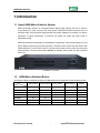
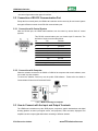
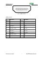
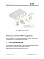
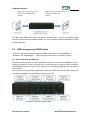
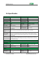
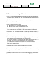
PTN Electronics
HDMI Matrix Switchers System
(Excluding MHD44)
User Manual
MHD Series --- HDMI Matrix Switcher
HDMI Matrix Switcher
Please read this manual carefully before using this product.
Notes:
This HDMI Matrix Switchers User Manual takes example of the Matrix model
MHD88.
This manual is only an instruction for operators, not for any maintenance usage.
The functions described in this version are updated till Aug 2011. Any changes of
functions and parameters since then will be informed separately. Please refer to
the dealers for the latest details.
This manual is copyright PTN Electronics Limited. All rights reserved. No part of
this publication may be copied or reproduced without the prior written consent of
PTN Electronics Limited.
All product function is valid till 2011-11-1
PTN Electronics Limited
ii
www.PTN-electronics.com
HDMI Matrix Switcher
! Safety Operation Guide
In order to guarantee the reliable operation of the equipments and safety of the staff,please
abide by the following proceeding in installation, using and maintenance:
⑴
The system must be earthed properly. Please do not use two blades plugs and ensure the alternating
power supply ranged from 100v to 240v and from 50Hz to 60Hz.
⑵
Do not put the switcher in a place of too hot or too cold.
⑶
As the power generating heat when running, the working environment should be maintained
fine ventilation, in case of damage caused by overheat.
⑷
Please cut off the general power switch in humid weather or left unused for long time.
⑸
Before following operation, ensure that the alternating current wire is pull out of the power
supply:
A. Take off or reship any components of the equipment.
B. Take off or rejoin any pin or other link of the equipment.
⑹
As to non-professional or without permission, please DO NOT try to open the casing of the
equipment, DO NOT repair it on your own, in case of accident or increasing the damage of the
equipment.
⑺
DO NOT splash any chemistry substance or liquid in the equipment or around.
PTN Electronics Limited
iii
www.PTN-electronics.com
HDMI Matrix Switcher
Contents
1. Introduction .........................................................................................................................1
1.1
About HDMI Matrix Switcher System ...................................................................................... 1
1.2
HDMI Matrix Switcher Models ................................................................................................. 1
2. MHD Packing of the Product ............................................................................................2
3. MHD Installation..................................................................................................................2
4. Front View and Rear View of the Product ......................................................................2
4.1
Front view of MHD88 ................................................................................................................ 2
4.2
Rear view of MHD88.................................................................................................................. 3
4.3
Front view of MHD1616 ............................................................................................................ 3
4.4
Rear view of MHD1616 .............................................................................................................. 3
5. External Connection ..........................................................................................................3
5.1
Introduction of the Input and Output Connectors.................................................................... 3
5.2
Connection of RS-232 Communication Port ............................................................................. 4
5.2.1
Connection with Control System .................................................................................................... 4
5.2.2
Connection with Computer ............................................................................................................. 4
5.3
How to Connect with the Input and Output Terminals ............................................................ 4
6. Operation of the EDID management ...............................................................................6
6.1
EDID automatically shake hand .............................................................................................. 6
6.2
EDID management of MHD matrix .......................................................................................... 7
7. Operation of the Control Panel ........................................................................................8
7.1 Front Panel Description .................................................................................................................. 8
7.2 Command Format of the Switching Operation .............................................................................. 9
7.3
Examples of Operation .............................................................................................................. 9
8. Usage of the Remote Controller ...................................................................................... 10
9. Communication Protocol and Command Codes ....................................................... 11
10.
Specification .................................................................................................................. 14
11.
Troubleshooting & Maintenance ................................................................................ 15
PTN Electronics Limited
iv
www.PTN-electronics.com
HDMI Matrix Switcher
1. Introduction
1.1 About HDMI Matrix Switcher System
MHD series Matrix switcher is a high-performance digital signal switcher that can be used for
cross switching of multi computer and audio signal. Independent HDMI component and I/O
terminals make each component signal transmit and switch separately; this design can reduce
attenuation of signal transmission to minimum and output the image and audio signal in
high-fidelity quality.
MHD series switcher mostly apply in broadcasting TV engineering, multi-media meeting room, big
screen display engineering, television education, command control center and other fields. With
RS232 interface, it can be worked with PC, remote control system and any other far-end control
system devices. The user manual takes MHD88 as example, other models can take reference
from it too.
1-1 MDH88 front view
1.2
HDMI Matrix Switcher Models
According to different situation and users, the HDMI series can be classified into the following models:
Specification
Video Inputs
Video Outputs
Audio Inputs
Audio Outputs
RS232
MHD88
8
8
x
x
√
MHD1616
16
16
x
x
√
MHD3232
32
32
x
x
√
MHD6464
64
64
x
x
√
Model
MHD9696
96
96
x
x
√
MHD128128
128
128
x
x
√
MHD144144
144
144
x
x
√
PTN Electronics Limited
1
www.PTN-electronics.com
HDMI Matrix Switcher
2. MHD Packing of the Product
HDMI Matrix Switcher
IR remote
RS-232 Communication Cord
Power Supply Cord
CD
User Manual and Quality Guarantee
3. MHD Installation
MHD matrix switchers adopt metal shell and can be stacked with other device. Moreover, they are
rack-mountable enclosure and can be installed in the standard 19 inches rack.
4. Front View and Rear View of the Product
4.1 Front view of MHD88
PTN Electronics Limited
2
www.PTN-electronics.com
HDMI Matrix Switcher
4.2 Rear view of MHD88
4.3 Front view of MHD1616
4.4 Rear view of MHD1616
5. External Connection
5.1 Introduction of the Input and Output Connectors
According to different type of matrix, computer signal I/O interface are made up of 4-channel
PTN Electronics Limited
3
www.PTN-electronics.com
HDMI Matrix Switcher
HDMI ports and DVI-D female ports respectively (digital audio included). Please refer to shell
silk-screen figure about other types of interface.
5.2 Connection of RS-232 Communication Port
Except the front control panel, the HDMI matrix switcher can be control by far-end control system
through the Ethernet control via the RS-232 communication port.
5.2.1 Connection with Control System
With the RS-232 port, the HDMI matrix switchers can be control by several kinds of control
systems.
This RS-232 communication port is a female 9-pin D connector. The
definition of its pins is as the table below.
No.
Pin
Function
1
N/u
Unused
2
Tx
Transmit
3
Rx
Receive
4
N/u
Unused
5
Gnd
Ground
6
N/u
Unused
7
N/u
Unused
8
N/u
Unused
9
N/u
Unused
F 5-1 9HDF
5.2.2 Connection with Computer
When the switcher connects to the COM1 or COM2 of the computer with control software, users
can control it by that computer.
To control the switcher, users may use the public COM software. Please refer the details in
Communication Protocol and Command Codes
F 5-2 MHD connecting to computer
5.3 How to Connect with the Input and Output Terminals
The HDMI matrix switchers may take DVD players, computers, graphic workstations and digital
showing platform as their input signal source, and projectors, video recorders, displayers and
amplifiers as their output signal destinations according to different situation.
PTN Electronics Limited
4
www.PTN-electronics.com
HDMI Matrix Switcher
F5—3 HDMI connector
HDMI pin function
Pin
Number
Signal Name
Pin
Number
Signal Name
1
TMDS Data 2+
20
SHELL
2
TMDS Data 2 Shield
19
Hot Plug Detect
3
TMDS Data 2-
18
+5V Power
4
TMDS Data 1+
17
Ground
5
TMDS Data 1 Shield
16
DDC Data
6
TMDS Data 1-
15
DDC Clock
7
TMDS Data 0+
14
No Connect
8
TMDS Data 0 Shield
13
CEC
9
TMDS Data 0-
12
TMDS Clock-
10
TMDS Clock+
11
TMDS Clock Shield
PTN Electronics Limited
5
www.PTN-electronics.com
HDMI Matrix Switcher
System Diagram:
F5-4 HDMI matrix system connection
6. Operation of the EDID management
MHD matrix switcher is built in the EDID management database. The EDID management can be
automatically shake hand, or manual exchanged, and factory restore.
6.1
EDID automatically shake hand
The MHD matrix switcher is built in the EDID data, which can communicate with the displayers and
video source automatically. When the displayers or video sources are connected to the MHD matrix
switcher, they will share the EDID/DDC information with the matrix switcher.
We take a MHD88 as example. The communication solution is like this:
PTN Electronics Limited
6
www.PTN-electronics.com
HDMI Matrix Switcher
The MHD EDID database includes most popular displaying data, but not all the displaying data
because of the capability and firmware limitation. So, we can manually refresh the EDID data to update
the EDID data base.
6.2
EDID management of MHD matrix
The RS232 commands for EDID management of MHD matrix models include: “EDIDMAuto.”
”EDIDMInit.” and ”EDIDM[X]B[Y].”, (Please notice the text-transform, and the dot in behind.)
6.2.1 Erase and Refresh the EDID data
The EDID refresh ports have the priority grade when the matrix is executing the EDIDMAuto function,
ranging from output 1 to output 8 in priority order. It means the output 1 is the most prior to exchange
the EDID data, and then the output 2 is the second prior to exchange the EDID data. And, the output 8
is the last prior.
When the user carries the EDID erase/refresh function, the MHD will detect the output priority and
exchange the EDID data with the available most prior output port.
Example of 8x8 matrix switcher priority.
PTN Electronics Limited
7
www.PTN-electronics.com
HDMI Matrix Switcher
6.2.2 Auto EDID management
The only way for auto EDID management is by sending RS232 commands “EDIDMAuto.”. When the
“EDIDMAuto.” is sent, the MHD matrix switcher will copy the EDID data from the most prior output port.
It means the MHD will erase the old EDID data, and fully copy the EDID data from the displayer which is
connected to the most prior output port. The feedback command is “EDIDMAuto”.
6.2.3 EDID restore to factory default
There are two ways to do restore EDID management: by RS232 command or by buttons.
EDID management by RS232 command
When we send the “EDIDMInit.” to the MHD matrix switcher, it will recover the factory default EDID data.
The feedback command is “EDIDMInit”.
EDID management by buttons
Press the button “INITIAL” on the front panel, the MHD matrix switcher will restore the EDID to factory
default.
6.2.4 Manually EDID switching
There are two ways to do manually EDID management: by RS232 command or by buttons.
EDID management by RS232 command
When we send the RS232 command “EDIDM[X]B[Y].”. The matrix will copy the EDID data of output[X]
to the input[Y]. The feedback command is “EDIDM: [X]To[Y]”.
EDID management by buttons
Press the button “EXTERNAL” then input button [X], and then press output button [Y]. The matrix will
copy the EDID data of the output[X] to the input[Y].
NOTICE: If the output[X] does not connect to an active display, the EDID management will take no
action.
6.3.5 RS232 feedback:
When a RS232 command is correctly sent, all the connected displayers will be blank for 2~3 seconds
and recover again. And, the MHD matrix switcher will send out the RS232 feedback command.
If all these symbols works, it means the action is taken.
7. Operation of the Control Panel
7.1 Front Panel Description
“AV”
AV synchronal button: To transfer video and audio signal synchronously by the switcher
Example: To transfer both the video and the audio signals from input channel No.3 to
output channel No.4.
Operation: Press buttons in this order “AV”,“3”,, “4””.
PTN Electronics Limited
8
www.PTN-electronics.com
HDMI Matrix Switcher
“INITIAL”
“EXTERNAL”
“1,2,3,4”
INITIAL button: To take the restore factory EDID management.
Operation: Press this button to recover the default factory EDID data.
EXTERNAL button: To take the manually EDID switching.
Example: To copy the EDID data of the display on output channel No.2 to the input
channel No.3.
Operation: Press buttons in this order: “EXTERNAL”, “2” in INPUT area, and then “3”
in OUTPUT area.
I/O Keypads: Keys to select I/O channels.
Example: To transfer input channel No.3 to output channel No.1
Operation: Press buttons in this order: “3” in INPUT area, “1” in OUTPUT area.
7.2 Command Format of the Switching Operation
With the front control panel, the switcher could be control directly and rapidly by pressing the buttons
under below format.
“Menu” +“Input Channel” +“Output Channel 1”
“Menu”: “AV”, “INITIAL”, “EXTERNAL”
“Input Channel”: Fill with the number of input channel to be controlled
“Output Channel”: Fill with the number of output channels to be controlled
7.3
Examples of Operation
Example 1:To transfer video and audio signals from input channel No.1 to output channel
No.3,4
AV
Video
Audio
1, Press the button for switching mode “AV” for the switching mode of video
and audio
1
2
2
2
3
3
3
4
4
4
2, Press the button for input channel number“1”
3,Press the button for the first output channel number “3”
”
4, Press the button for the second output channel number “4”
Then, switching OK !
PTN Electronics Limited
audio/video switching from “1” to “3” and “4”
9
www.PTN-electronics.com
HDMI Matrix Switcher
8. Usage of the Remote Controller
With the infrared remote controller, the matrix switcher could be control remotely. Because the function
buttons on the remote controller are the same with the ones on the front control panel, the remote
controller shares the same control operation and command format with the control panel.
The inputs
channels, from
0~9, and
plusing “10+”
for more
Menu, for
switching
source and
function
The outputs
channels, from
0~9, and
plusing “10+”
for more
PTN Electronics Limited
10
www.PTN-electronics.com
HDMI Matrix Switcher
9. Communication Protocol and Command
Codes
With this command system, the RS232 software is able to control and operate the MHD Matrix with
remotely.
Communication protocol:
Baud rate: 9600
Data bit: 8
Stop bit: 1
Parity bit: none
Command
Types
Command
Codes
Functions
System
Command
/*Type;
Inquire the models information.
/%Lock;
Lock the keyboard of the control panel on the Matrix.
/%Unlock;
Unlock the keyboard of the control panel on the Matrix.
/^Version;
Inquire the version of firmware
/:MessageOff;
Turn off the feedback command from the com port. It will only show
the “switcher OK”.
/:MessageOn;
Turn on the feedback command from the com port.
EDIDMAuto.
Refresh the EDID data with the most priority output port.
EDIDMInit.
Recover the factory default EDID data.
EDIDM[X]B[Y].
Manually EDID switching. Copy the EDID data of output[X] to the
input[Y].
Undo.
To cancel the previous operation.
Demo.
Switch to the “demo” mode, 1->1, 2->2, 3->3 … and so on.
Operation Command
(PTN2.0 Command System)
[x1]All.
Transfer signals from the input channel [x1] to all output channels
All#.
Transfer all input signals to the corresponding output channels
respectively.
All$.
Switch off all the output channels.
[x1]#.
Transfer signals from the input channel [x1] to the output channel
[x1].
[x1]$.
Switch off the output channel [x1].
[x1] V[x2].
Transfer the video signals from the input channel [x1] to the output
channel [x2].
[x1]
V[x2],[x3],[x4].
Transfer the video signals from the input channel [x1] to the output
channels [x2], [x3] and [x4].
[x1] A[x2].
Transfer the audio signals from the input channel [x1] to the output
channel [x2].
[x1]
A[x2],[x3],[x4].
Transfer the audio signals from the input channel [x1] to the output
channels [x2], [x3] and [x4].
[x1] B[x2].
Transfer both the video and the audio signals from the input channel
[x1] to the output channel [x2].
PTN Electronics Limited
11
www.PTN-electronics.com
HDMI Matrix Switcher
[x1]
B[x2],[x3],[x4].
Transfer both the video and the audio signals from the input channel
[x1] to the output channels [x2], [x3] and [x4].
[x1]P[g].
Transfer both the video and the audio signals from the input channel
[x1] to the output group [g].
[g]PP[x2],[x3],[x
4].
Together the output channels [x2], [x3] and [x4] to the output group
[g].
S[g].
Inquire the output channels of output group [g].
Status[x1].
Inquire the input channel to the output channel [x1].
Status.
Inquire the input channel to the output channels one by one.
Save[Y].
Save the present operation to the preset command [Y]. [Y] ranges
from 0 to 9.
Recall[Y].
Recall the preset command [Y].
Clear[Y].
Clear the preset command [Y].
Remarks: Dot is one part of the RS232 code!
Note:
1. [x1], [x2], [x3] and [x4] are the symbols of input or output channels ranged according to the
model of the matrix switcher. If the symbols exceed the effective range, it would be taken as a
wrong command.
2. In above commands, “[”and “]” are symbols for easy reading and do not need to be typed in
actual operation.
3. Please remember to end the commands with the ending symbols “.” and “;”.
Detail Examples:
1、 Transfer signals from an input channel to all output channels: [x1]All.
Example: To transfer signals from the input channel No.3 to all output channels. Run Command:
“3All.”
2、 Transfer all input signals to the corresponding output channels respectively: All#.
Example: If this command is carried out on an MVG1616-A matrix switcher, the status of it will be:
1->1, 2->2, 3->3, 4->4……16->16.
3、 Switch off all the output channels: All$.
Example: After running this command, there will be no signals on all the output channels.
4、 Check the version of the firmware: /^Version;
To check the version of the firmware.
5、 Switch off the detail feedback command from the COM port: /:MessageOff;
Switch off the detail feedback information from the COM port. But, it will leave the “switch OK” as
the feedback, when you switch the matrix.
6、 Switch on the detail feedback command from the COM port: /:MessageOn;
Switch on the detail feedback information from the COM port. it will show the detail switch
information when it switch. Example: when switch 1->2 for Audio, it will feedback “A0102”.
7、 Transfer signals from an input channel to the corresponding output channel: [x]#.
Example: To transfer signals from the input channel No.5 to the output channel No.5.
Command: “5#.”
PTN Electronics Limited
12
www.PTN-electronics.com
Run
HDMI Matrix Switcher
8、Switch off an output channel: [x]$.
Example: To switch off the output channel No.5.
Run Command: “5$.”
9、Switch both video and audio signals synchronously: [x1] B[x2].
Example: To transfer both the video and the audio signals from the input channel No.120 to the
output channel No.12,13,15. Run Command: “120B12,13,15.”
10、Transfer both the video and audio signals from input channel [x1] to output group [g]:
[x1]P[g].
Example: If together the output channel NO.1,3,5,7 to output group NO.2 by sent the command
“2PP1,3,5,7.”, then when send the command “1P2.”, the matrix will transfer both the video and
the audio signals from the input channel No.1 to output channel NO.1,3,5,7.
When you want to make a group [g], you should clear this group first. The command for clear
group is “[g]P0.”.
11、Inquire the input channel to the output channel [x]: Status[x].
Example: To inquire the input channel to the output channel No.23.
Run Command: “Status23.”
12、Inquire the input channel to the output channels one by one: Status.
Example: To inquire the input channel to the output channels one by one.
“Status.”
Run Command:
13、Save the present operation to the preset command [Y]: Save[Y].
Example: To save the present operation to the preset command No.7.
Run Command: “Save7.”
14、Recall the preset command [Y]: Recall[Y].
Example: To recall the preset command No.5. Run Command: “Recall5.”
15、Clear the preset command [Y]: Clear[Y].
Example: To clear the preset command No.5.
PTN Electronics Limited
13
Run Command: “Clear5.”
www.PTN-electronics.com
HDMI Matrix Switcher
10. Specification
Video Input
Video Output
Input
HDMI
Output
HDMI
Input Connector
HDMI 1.3
Output Connector
HDMI 1.3
Input Level
T.M.D.S. 2.9V/3.3V
Output Level
T.M.D.S. 2.9V/3.3V
Input Impedence
75Ω
Output Impedence
75Ω
Gain
0 dB
Bandwidth
340 MHz (10.2 Gbit/s)
Video Signal
HDMI (or DVI-D)
Video General
Resolution Range
Up to 1920 x 1200 or
1080P@60Hz
Maximum Pixel
165MHz
Clock
Switching Speed
2 – 5 seconds
Consumer
Electronics Control
Supports CEC wired infrared data pass-through using the HDMI 1.3 standard
(CEC)
Supports Extended Display Identification Data (EDID) and Display Data Channel (DDC) data
EDID and DDC
using DVI and HDMI standards, EDID and DDC signals are actively buffered. The built-in
Management
EDID/DDC database can analyze these two signals, mix them, and realize the handshake of
them internally.
Compliant with High-bandwidth Digital Content Protection (HDCP) using DVI and HDMI 1.3
HDCP Management
standards. The built-in HDCP management technology can analyze HDCP key, and realize
the handshake internally.
Audio General
Digital Audio
Supports HDMI audio transmitted through the RGB and Y, Cr, Cb lines, actively buffered
Control Parts
Serial Control Port
RS-232, 9-pin female D
connector
Pin Configurations
2 = TX, 3 = RX, 5 = GND
Front Panel Control
Buttons
IR Remote
Default IR remote
Options
TCP/IP control by PTNET(PTN's programmable interface)
General
Power Supply
100VAC ~ 240VAC, 50/60Hz
Power Consumption
25W
Temperature
-20 ~ +70℃
Humidity
10% ~ 90%
PTN Electronics Limited
14
www.PTN-electronics.com
HDMI Matrix Switcher
Case Dimension
W483 x H87 x D320mm
(2U high, full rack wide)
Product Weight
2.5Kg
11. Troubleshooting & Maintenance
1)
When the output image in the destination device connected to theHDMI Matrix (MHD) has ghost,
such as the projector output with ghost, please check the projector’s setting or try another high
quality connection cord.
2)
When there is a color losing or no video signal output,,Maybe the HDMI cables haven’t been
connected asHDMI criterion
3)
When the remote controller doesn’t works:
A. Maybe the battery is run out of, please change a new one.
B. Maybe the controller is broken, please ask the dealer to fix it.
4)
When user can not control the HDMI Matrix (MHD) by computer through its COM port, please
check the COM port number in the software and make sure the COM port is in good condition.
5)
If there is not “beep” sound when switching the I/O signal, please make sure the beeper is
switched-on. If so, the beeper inside the matrix may be broken. Please send it to the dealer for
fixing.
6)
When switching , the beeper beeps but without any output image:
A. Check with oscilloscope or multimeter if there is any signal at the input end. If there is no signal
input, it may be the input connection cord broken or the connectors loosen.
B. Check with oscilloscope or multimeter if there is any signal at the output end. If there is no
signal output, it may be the output connection cord broken or the connectors loosen.
C. Please make sure the destination device is exactly on the controlled output channel
D. If it is still the same after the above checking, it may be something wrong in the switcher.
Please send it to the dealer for fixing.
7)
If the output image is interfered, please make sure the system is earthed well.
8)
If the static becomes stronger when connecting the HDMI connectors, it may be due to the
incorrect earthling of the power supply, Please earth it again correctly, and otherwise it would bring
damage to the switcher or shorten its natural life.
9)
If the Matrix can not be controlled by the keys on the front panel, RS232 port or remote controller,
PTN Electronics Limited
15
www.PTN-electronics.com
HDMI Matrix Switcher
the host may has already been broken. Please send it to the dealer for fixing.
Remarks: For any more questions or problems, please try to get help from your local distributor, or
email PTN at [email protected].
PTN Electronics Limited
16
www.PTN-electronics.com