1
Troubleshooting
Drying Tumblers
50 Pound Capacity
75 Pound Capacity
Refer to Page 5 for Model Numbers
T012c
www.comlaundry.com
Part No. 70410501
September 2007
Table of
Contents
Section 1 – Safety Information ...............................................................3
Locating An Authorized Service Person ...............................................4
Section 2 – Introduction ..........................................................................5
Model Identification ..............................................................................5
Customer Service...................................................................................6
Serial Plate Location..............................................................................6
Safety Warnings and Decals..................................................................7
Safety Precautions for Servicing Tumblers ...........................................7
How A Tumbler Works .........................................................................8
Section 3 – Troubleshooting..................................................................10
1. Motor Does Not Start..................................................................11
2. Motor Overload Protector Cycles Repeatedly ............................13
3. Motor Runs But Cylinder Does Not Turn...................................14
4. Motor Does Not Stop ..................................................................15
5. Heating Element Does Not Heat Or Burner Does Not Ignite
– Gas and Electric Models ..........................................................16
6. Pilot Does Not Ignite – Standing Pilot Ignition Gas Models......18
7. Pilot Goes Out – Standing Pilot Ignition Gas Models ................19
8. Igniter Does Not Shut Off After Gas Ignition
– Automatic Pilot Ignition Gas Models ......................................20
9. Gas Supply Sufficient But Igniter Does Not Glow
– Glow-Bar Ignition Gas Models................................................21
10. Igniter Glows, Sensor Opens But No Ignition
– Johnson Controls System Gas Models.....................................22
11. Igniter Glows, Sensor Opens But No Ignition
– White Rodgers Glow-Bar Ignition Gas Models.......................23
12. Burner Ignites and Goes Out Repeatedly
– Glow-Bar Ignition Gas Models................................................24
13. Heating Element or Burner Shuts-Off Prematurely....................25
14. Heating Element or Burner Repeatedly Cycles Off On
High Limit Thermostat................................................................26
15. Heating Element or Burner Does Not Shut-Off..........................27
16. Clothes Do Not Dry ....................................................................28
17. Tumbler Overheating ..................................................................29
18. Burners Not Burning Properly – Gas Models.............................30
19. Loading Door Opens During Operation......................................31
20. Tumbler Runs But No Steam To Coils – Steam Models ............32
21. Water In Steam Line – Steam Models ........................................33
22. Troubleshooting Electronic Control Models...............................34
23. Tumbler Will Not Start, Time on Drying Timer,
Door Closed – Manual Timer Models ........................................36
24. Motor Runs, Time on Drying Timer But No Heat......................37
25. No Spark to Pilot Burner – Electronic Pilot Ignition Models .....39
26. Spark to Pilot Burner, No Pilot Flame
– Electronic Pilot Ignition Models ..............................................40
27. Spark To Pilot Burner, Pilot Lights, No Main Burner
– Electronic Pilot Ignition Models ..............................................41
© Copyright 2007, Alliance Laundry Systems LLC
All rights reserved. No part of the contents of this book may be reproduced or transmitted in any form or by any means without
the expressed written consent of the publisher.
70410501
© Copyright, Alliance Laundry Systems LLC – DO NOT COPY or TRANSMIT
1
28. Igniter Does Not Glow – Johnson Controls
Glow-Bar System........................................................................42
29. Igniter Glows Constantly – Johnson Controls and
White Rodgers Glow-Bar System...............................................43
30. Igniter Glows, Cycles Off But Burner Does Not Ignite
– Johnson Controls Glow-Bar System ........................................44
31. Igniter Does Not Glow – White Rodgers Glow-Bar System ......45
32. Igniter Glows, Cycles Off But Burner Does Not Ignite
– White Rodgers Glow-Bar System............................................46
33. Igniter Sparks, No Main Burner Ignition
– Instant Electronic Ignition........................................................47
34. CSH OM Models: No Heat With Cycle Selected,
Unit Running and Calling For Heat ............................................48
35. OM Models: No Start With Cycle Selected, Start Button
Pressed and Door Closed ............................................................50
36. OM Models: No Display After Selecting One Of The
ON/SELECT Keys......................................................................52
37. CE OM Models: No Heat With Cycle Selected, Unit
Running and Calling For Heat ....................................................53
38. CG OM Models: No Heat With Cycle Selected, Unit
Running and Calling For Heat ....................................................55
39. OM Models: No Fan Motor Rotation With Cycle Selected
and Start Pressed .........................................................................57
40. MM Models: Fan Motor Does Not Run With Door Closed,
Cycle Selected and Start Button Pressed ....................................58
41. MM Models: Cylinder Motor Does Not Run or Reverse With
Door Closed, Cycle Selected and Start Button Pressed In
Reversing Mode or Nonreversing Mode.....................................59
42. MM Models: No Heat With Cycle Selected, Unit Running
and Calling For Heat ...................................................................61
43. MM Models: No Heat With Cycle Selected, Unit Running
and Calling For Heat ...................................................................63
44. OM Reversing Models: No Cylinder Rotation or Reversing
Capabilities..................................................................................65
45. MM Models: No Display After Pressing the ON/SELECT
Keys ............................................................................................67
46. MM Models: Motor Does Not Run With Door Closed, Cycle
Selected and Start Button Pressed...............................................68
47. MM Models: Cylinder Motor Does Not Run or Reverse With
Door Closed, Cycle Selected and Start Button Pressed In
Reversing Mode or Nonreversing Mode.....................................69
48. MM Nonreversing Models: Motor Does Not Run With Door
Closed, Cycle Selected and Start Button Pressed .......................71
49. CD Models: No Start With Vend Satisfied and Start Button
Pushed .........................................................................................73
50. CD Models: No Heat With Vend Satisfied and Unit Running ...75
51. CD Models: No Heat With Vend Satisfied and Unit Running ...77
52. CD Models: No Start With Vend Satisfied and Start Button
Pushed .........................................................................................79
53. CD Models: No Start With Vend Satisfied and Start Button
Pushed .........................................................................................81
Section 4 – Adjustments ........................................................................82
54. Cylinder Clearance......................................................................82
2
© Copyright, Alliance Laundry Systems LLC – DO NOT COPY or TRANSMIT
70410501
Section 1
Safety Information
Throughout this manual and on machine decals, you
will find precautionary statements (“CAUTION”,
“WARNING”, and “DANGER”) followed by specific
instructions. These precautions are intended for the
personal safety of the operator, user, servicer, and those
maintaining the machine.
DANGER
DANGER indicates the presence of a
hazard that will cause severe personal
injury, death, or substantial property
damage if the danger is ignored.
WARNING
WARNING indicates the presence of a
hazard that can cause severe personal
injury, death, or substantial property
damage if the warning is ignored.
In the interest of safety, some general precautions
relating to the operation of this machine follow.
WARNING
• Failure to install, maintain and/or operate
this product according to the
manufacturer’s instructions may result in
conditions which can produce serious
injury, death and/or property damage.
• Do not repair or replace any part of the
product or attempt any servicing unless
specifically recommended or published in
this Service Manual and unless you
understand and have the skills to carry
out the servicing.
• Whenever ground wires are removed
during servicing, these ground wires
must be reconnected to ensure that the
product is properly grounded and to
reduce the risk of fire, electric shock,
serious injury or death.
W006R2
CAUTION
CAUTION indicates the presence of a
hazard that will or can cause minor
personal injury or property damage if the
caution is ignored.
Additional precautionary statements (“IMPORTANT”
and “NOTE”) are followed by specific instructions.
IMPORTANT: The word “IMPORTANT” is used
to inform the reader of specific procedures where
minor machine damage will occur if the procedure
is not followed.
NOTE: The word “NOTE” is used to communicate
installation, operation, maintenance or servicing
information that is important but not hazard
related.
70410501
© Copyright, Alliance Laundry Systems LLC – DO NOT COPY or TRANSMIT
3
Safety Information
IMPORTANT INFORMATION: During the
lifetime of a tumbler, it may require service. The
information contained in this manual was written
and is intended for use by qualified service
technicians who are familiar with the safety
procedures required in the repair of a tumbler, and
who are equipped with the proper tools and testing
equipment.
NOTE: The WARNING and IMPORTANT
instructions appearing in this manual are not meant
to cover all possible conditions and situations that
may occur. It must be understood that common
sense, caution and carefulness are factors which
CANNOT be built into this tumbler. These factors
MUST BE supplied by the person(s) installing,
maintaining or operating the tumbler.
Always contact your dealer, distributor, service agent
or the manufacturer on any problems or conditions you
do not understand.
WARNING
To reduce the risk of electric shock, fire,
explosion, serious injury or death:
• Disconnect electric power to the tumbler
before servicing.
• Never start the tumbler with any guards/
panels removed.
• Whenever ground wires are removed
during servicing, these ground wires
must be reconnected to ensure that the
tumbler is properly grounded.
W240
WARNING
Locating An Authorized Service
Person
Alliance Laundry Systems is not responsible for
personal injury or property damage resulting from
improper service. Review all service information
before beginning repairs.
Warranty service must be performed by an
authorized technician, using authorized factory
parts. If service is required after the warranty
expires, Alliance Laundry Systems also
recommends contacting an authorized technician
and using authorized factory parts.
Repairs that are made to your products by
unqualified persons can result in hazards
due to improper assembly or adjustments
subjecting you or the inexperienced person
making such repairs to the risk of serious
injury, electrical shock or death.
W007
CAUTION
If you or an unqualified person perform
service on your product, you must assume
the responsibility for any personal injury or
property damage which may result. The
manufacturer will not be responsible for
any injury or property damage arising from
improper service and/or service
procedures.
W008
4
© Copyright, Alliance Laundry Systems LLC – DO NOT COPY or TRANSMIT
70410501
Section 2
Introduction
Model Identification
Information in this manual is applicable to these models:
50
Pound
75
Pound
70410501
ATB50CG
DCB50CG
DCB50EG
DTB50CG
DTB50EG
JC50CG
JC50EG
JCB50CG
JCB50EG
JT37CG
JT37CGI
JT37EG
JT37EGI
JT50CG
JT50CGI
JT50EG
ATB75CG
DCB75CG
DCB75FG
DTB634
DTB75CG
DTB75EG
DTB75FG
JCB75CG
Gas
JT50EGI
JTB50CG
JTB50EG
SC50CG
SC50EG
SCB50CG
SCB50EG
ST37CG
ST37CGI
ST37EG
ST37EGI
ST50CGI
ST50EGI
STB50CG
STB50EG
TKD50CGMT
JT75CG
JT75EG
JTB75CG
JTB75EG
SCB75CG
ST75CG
STB634
STB75CG
STB75EG
Steam/Thermal Oil
ATB50CSH
JTB50CSH
DCB50CSH
JTB50CSL
DTB50CSH
SC50CSH
DTB50CSL
SCB50AT
JC50CSH
SCB50CSH
JCB50CSH
ST37CSH
JT37CSH
ST37CSL
JT37CSL
ST50CSH
JT50CSH
ST50CSL
JT50CSL
STB50CSH
STB50CSL
Electric
DCB50CE
DTB50CE
JC50CE
JCB50CE
JT37CE
JT50CE
JTB50CE
SC50CE
SCB50CE
ST37CE
ST50CE
STB50CE
TKD50CEMT
ATB75CSH
DCB75CSH
DCB75CSL
DTB75CSH
DTB75CSL
JCB75CSH
JCB75CSL
JT75CSH
JT75CSL
DCB75CE
DTB75CE
JCB75CE
JT75CE
JTB75CE
SCB75CE
ST75CE
STB75CE
JTB75CSH
JTB75CSL
SCB75CSH
SCB75CSL
ST75CSH
ST75CSL
STB75CSH
STB75CSL
© Copyright, Alliance Laundry Systems LLC – DO NOT COPY or TRANSMIT
5
Introduction
Customer Service
If literature or replacement parts are required, contact
the source from whom the machine was purchased or
contact Alliance Laundry Systems at (920) 748-3950
for the name and address of the nearest authorized
parts distributor.
For technical assistance, call (920) 748-3121.
Serial Plate Location
When calling or writing about your product, be sure to
mention model and serial numbers. Model and serial
numbers are located on serial plate(s) as shown.
T419IE3B
6
© Copyright, Alliance Laundry Systems LLC – DO NOT COPY or TRANSMIT
70410501
Introduction
Safety Warnings and Decals
SAFETY WARNINGS and decals have been provided
in key locations to remind you of important precautions
for the safe operation and maintenance of your tumbler.
Please take the time to review these warnings before
proceeding with service work.
All decals have been designed and applied to withstand
washing and cleaning. Decals should be checked
periodically to be sure they have not been damaged,
removed, or painted. Refer to Parts Manual for
ordering replacement decals.
Safety Precautions for Servicing Tumblers
• Disconnect electrical service.
• Shut off supply gas valve before servicing gas
components.
• Control panel and access panel MUST be
reinstalled after inspection or servicing of
tumbler is completed.
• Use a non-corrosive leak detection fluid to check
all pipe connections for gas leaks. DO NOT USE
AN OPEN FLAME TO CHECK FOR GAS
LEAKS!
• Chain/drive guard MUST be reinstalled after
inspection or servicing of tumbler is completed.
• Belt guard MUST be reinstalled after inspection
or servicing of tumbler is completed.
• Contactor box cover MUST be reinstalled after
inspection or servicing of electric and/or reversing
tumbler is completed.
• Loading door switch MUST be operational before
putting tumbler into service.
• Junction box cover MUST be reinstalled after
inspection or servicing of tumbler is completed.
70410501
© Copyright, Alliance Laundry Systems LLC – DO NOT COPY or TRANSMIT
7
Introduction
How A Tumbler Works
Fresh Air
Combustion Air
Mixed Air
Exhaust Air
T008CE1A
Standard Models
The tumbler uses heat, air and movement to dry
loads of laundry.
NOTE: In Energy Saver Models, some of the
exhaust air is recirculated. Refer to illustration on
next page.
When the motor is started, the exhaust fan pulls
fresh air in through the air intake and over the heat
source (burner flame for gas, heating element for
electric, and coil for steam).
The heated air moves into the cylinder, where it is
circulated through the laundry by the tumbling
action of the cylinder.
The air then passes through the lint filter, exhaust
fan, and is vented to the outdoors.
8
© Copyright, Alliance Laundry Systems LLC – DO NOT COPY or TRANSMIT
70410501
Introduction
Fresh Air
Combustion Air
Mixed Air
Recirculating Air
Exhaust Air
T007CE1A
Energy Saver Models
70410501
© Copyright, Alliance Laundry Systems LLC – DO NOT COPY or TRANSMIT
9
Section 3
Troubleshooting
WARNING
To reduce the risk of electric shock, fire, explosion, serious injury or death:
• Disconnect electric power to the tumbler before servicing.
• Close gas shut-off valve to gas tumbler before servicing.
• Close steam valve to steam tumbler before servicing.
• Never start the tumbler with any guards/panels removed.
• Whenever ground wires are removed during servicing, these ground wires must be
reconnected to ensure that the tumbler is properly grounded.
W002
IMPORTANT: Refer to wiring diagram for aid in
testing tumbler components.
10
© Copyright, Alliance Laundry Systems LLC – DO NOT COPY or TRANSMIT
70410501
Troubleshooting
1. Motor Does Not Start
Motor does
not start
Is the
electrical power
off or circuit breaker
fuse blown?
Is there
broken, loose, or
incorrect
wiring?
Yes
Check power
supply or replace
fuses.
Is the
loading door
not closed or switch
inoperative?
Yes
Close door or
test switch and
replace if
inoperative.
No
Is the
door switch
improperly
adjusted?
Yes
Refer to
Installation
Manual for
door switch
adjustment.
No
Is the start circuit
not complete?
Yes
Press
start switch
or test switch
and replace if
inoperative.
Is the motor
inoperative?
Yes
Have motor tested
and replace if
inoperative.
Yes
Check that proper
coins are inserted.
Yes
Turn knob
clockwise to its full
limit of travel.
No
Is
accumulator knob
improperly set
after coins were
inserted.
No
Is the
run switch
accumulator
inoperative?
Yes
Test run switch
and replace if
inoperative.
No
Is the
motor relay
inoperative?
No
Refer to wiring
diagram.
No
Are
improper
coins inserted in
accumulator?
No
Yes
Yes
Test relay and
replace if
inoperative.
No
continued on
next page
No
TMB2131S-a
70410501
© Copyright, Alliance Laundry Systems LLC – DO NOT COPY or TRANSMIT
11
Troubleshooting
1. Motor Does Not Start (continued)
Continued from
previous page
Are
trunnion bearings
binding?
Yes
Replace
trunnion
bearings.
Yes
Replace
bearings.
Yes
Turn drying timer
clockwise to
desired setting.
Yes
Test timer and
replace if
inoperative.
No
Are
idler bearings
binding?
No
Is timer
improperly
set?
No
Is timer
inoperative?
TMB2131S-b
12
© Copyright, Alliance Laundry Systems LLC – DO NOT COPY or TRANSMIT
70410501
Troubleshooting
2. Motor Overload Protector Cycles Repeatedly
Motor Overload
Protector
Cycles
Repeatedly
Yes
Is voltage
correct?
No
Is clothes
load too
large?
Yes
Refer to
Installation
Manual for
electrical
requirements.
Remove part of
load.
No
Is clothes
cylinder
binding?
Yes
Check cylinder
for binding.
No
Yes
Is wiring
adequate?
Check with
local power
company to
ensure that
wiring is
adequate.
No
Yes
Is make-up
air adequate?
Refer to
Installation
Manual for
make-up air
requirements.
No
Is there lint
buildup around
tumbler or poor
maintenance?
No
Clean lint
accumulation
on and around
the motors.
Yes
Is there
broken, loose
or incorrect
wiring?
Yes
Refer to wiring
diagram.
TMB1904S
70410501
© Copyright, Alliance Laundry Systems LLC – DO NOT COPY or TRANSMIT
13
Troubleshooting
3. Motor Runs But Cylinder Does Not Turn
Motor runs
but cylinder
does not turn
Is cylinder belt
broken or
loose?
Yes
Replace or
adjust cylinder
belt.
No
Is drive belt
broken or
loose?
Is sheave
loose?
Yes
Tighten
setscrews.
No
Replace or
adjust chain
or sprocket.
No
Yes
Replace or
adjust drive
belt.
Is
drive chain or
sprocket broken
or loose?
No
Is cylinder
binding?
Yes
Check cylinder
for binding.
Yes
Tighten drive
pulley bushing
screws.
No
Is motor drive
pulley loose?
No
TMB2132S
14
© Copyright, Alliance Laundry Systems LLC – DO NOT COPY or TRANSMIT
70410501
Troubleshooting
4. Motor Does Not Stop
Motor does
not stop
Is the door
switch not
working
properly?
Yes
Test switch and
replace if inoperative.
Refer to Installation
Manual for proper
switch adjustment.
No
Is wiring
incorrect?
Refer to wiring
diagram.
Yes
No
Is timer
or relay
inoperative?
Yes
Test timer
and relay
and replace
if inoperative.
No
Is
accumulator
inoperative?
Yes
Test
accumulator
and replace if
inoperative.
TMB2133S
70410501
© Copyright, Alliance Laundry Systems LLC – DO NOT COPY or TRANSMIT
15
Troubleshooting
5. Heating Element Does Not Heat Or Burner Does Not Ignite – Gas and
Electric Models
Heating element does
not heat or burner
does not ignite
Test switch and replace if
inoperative.
Is there
an improper or
inadequate exhaust
system?
Yes
Refer to
Installation
Manual for
exhaust system
requirements.
Are there
blown fuses or
Yes
tripped circuit breakers
in external electric
supply line?
Check exhaust outlet. If a
screen has been
improperly installed on
the outlet, it may be
clogged with lint or frozen
over in winter. NEVER
install a screen over the
exhaust outlet.
Check fuses or
circuit breaker.
Is airflow
switch out of
adjustment?
No
Yes
Set drying timer
or replace if
inoperative.
No
Is
thermostat
inoperative?
Yes
No
No
Is
drying timer
not selected or
inoperative?
Is the
airflow switch
inoperative?
Yes
Test thermostat
and replace if
inoperative.
Check back draft damper
for foreign objects, lint
accumulation or other
causes that may prevent
damper from opening.
Yes
Refer to Installation
Manual for airflow
switch adjustment.
No
Is the lint
door panel
not closed
properly?
Yes
Open lint door
panel, place lint
door and panel
back on tumbler
(ensuring a tight fit).
No
No
Is there
lint
buildup?
Yes
Clean lint compartment.
Check damper for lint
accumulation. Check
ductwork for lint buildup.
No
Is there
inadequate
ductwork and
make-up air?
Refer to Installation
Manual to ensure that
Yes
ductwork and make-up
air openings are sized
accurately.
Is
there broken,
loose or
incorrect
wiring?
Yes
No
Continued on
next page
TMB2134S-a
No
16
Refer to
wiring diagram.
© Copyright, Alliance Laundry Systems LLC – DO NOT COPY or TRANSMIT
70410501
Troubleshooting
5. Heating Element Does Not Heat Or Burner Does Not Ignite – Gas and
Electric Models (continued)
Continued from
previous page
Electric
Models: Are
heating elements
or contactors
inoperative?
No
Gas Models:
Is there an
insufficient gas
supply?
No
Gas Models:
Are the orifices
incorrect?
Gas Models:
Are gas valve coils
inoperative?
Yes
Open partially closed
gas shut-off valve or
correct low gas
pressure. Check
Yes manifold pressure and
adjust to pressure
specified on serial
plate. If pressure
cannot be obtained,
have your local gas
company check main
gas pressure.
Yes
No
Gas Models:
Is there an
inoperative
igniter?
Check heat
contactors and
elements.
Replace if
necessary.
Yes
Tumbler is equipped
for type of gas
specified on serial
plate. If orifices are
different from that
specified on serial
plate, obtain and
install correct orifices.
Test igniter
and replace if
inoperative.
Yes
Test coils and
replace if
necessary.
Yes
Test main coil
and replace if
inoperative.
No
Gas Models:
Is main coil
inoperative?
No
Gas Models:
Is redundant coil
inoperative?
Yes
Test redundant coil
and replace
complete gas valve
if inoperative.
No
Standing Pilot
Ignition Gas
Models: Is pilot
not lit?
Refer to Installation
Manual or
instruction
plate on
Yes
back of tumbler for
lighting and
shutting down
standing pilot.
No
Standing
Pilot Ignition Gas
Models: Is gas valve
reset assembly or
thermocouple
inoperative?
Yes
Check and
replace
thermocouple or
reset assembly
if necessary.
No
No
Gas Models:
Is the igniter control
inoperative?
Yes
Test igniter
control and
replace if
inoperative.
Glow Bar
Ignition Gas Models: Is
sensor inoperative?
Yes
TMB2134S-b
No
70410501
Test sensor
and replace if
inoperative.
© Copyright, Alliance Laundry Systems LLC – DO NOT COPY or TRANSMIT
17
Troubleshooting
6. Pilot Does Not Ignite – Standing Pilot Ignition Gas Models
Pilot does not
ignite - Standing Pilot
Ignition Gas Models
Is
gas shut-off
valve to
tumbler
closed?
Yes
Open valve.
Yes
No
Is pilot orifice
incorrect?
Yes
Replace
thermocouple.
Yes
Replace pilot
assembly.
No
No
Is air present
in gas line?
Is
thermocouple
inoperative?
Yes
Purge air from
gas line.
Is pilot
assembly
inoperative?
Tumbler is equipped
for type of gas
specified on serial
plate. If pilot orifice is
different from that
specified on serial
plate, obtain and
install correct orifice.
No
Is pilot gas
filter clogged?
Yes
Replace reset
assembly.
No
Is pilot
gas tube or
pilot orifice
clogged?
Yes
Clean or
replace tube
or orifice.
TMB2135S
No
18
© Copyright, Alliance Laundry Systems LLC – DO NOT COPY or TRANSMIT
70410501
Troubleshooting
7. Pilot Goes Out – Standing Pilot Ignition Gas Models
Pilot goes out Standing Pilot Ignition
Gas Models
Is exhaust
system
improper or
inadequate?
Yes
Refer to
Installation
Manual for
exhaust system
requirements.
No
Is lint screen
clogged?
Yes
No
Yes
Remove and
clean lint
screen.
No
Is burner
flame
Improperly
adjusted?
Is pilot orifice
incorrect?
Yes
Tumbler is
equipped for
type of gas
specified on
serial plate. If
pilot orifice is
different from
that specified
on serial plate,
obtain and
install correct
orifice.
Close air shutter
slightly - A harsh
roaring flame will
draw pilot flame out.
Is gas
valve reset
assembly or
thermocouple
inoperative?
Yes
Check and
replace reset
assembly or
thermocouple
if necessary.
No
Is there
carbon
accumulation
on heated end
of pilot
thermocouple?
Yes
Wipe carbon
off end of
thermocouple.
No
TMB2136S
70410501
© Copyright, Alliance Laundry Systems LLC – DO NOT COPY or TRANSMIT
19
Troubleshooting
8. Igniter Does Not Shut Off After Gas Ignition – Automatic Pilot Ignition
Gas Models
Igniter does not shut off
after gas ignition Automatic Pilot Ignition
Gas Models
Is tumbler
not properly
equipped for
type of gas
being used?
Yes
Tumbler is equipped
for type of gas
specified on serial
plate. If tumbler is
equipped for gas
different from that
specified on serial
plate, obtain the
necessary
components to
correct the problem.
Is igniter
control
inoperative?
Yes
Test igniter
control and
replace if
inoperative.
No
No
Is gas supply
insufficient?
Yes
Open partially closed
gas shut-off valve or
correct low gas
pressure.
Is wiring
incorrect?
No
Is burner
flame
improperly
adjusted?
Yes
Refer to Installation
Manual for
recommended
burner flame
adjustment.
Refer to wiring
Yes diagram located
on back of
tumbler or in
literature
packet.
No
Is pilot and
electrode
assembly
incorrectly
installed?
Yes
Check assembly
for correct
alignment.
No
TMB2137S
20
© Copyright, Alliance Laundry Systems LLC – DO NOT COPY or TRANSMIT
70410501
Troubleshooting
9. Gas Supply Sufficient But Igniter Does Not Glow – Glow-Bar Ignition Gas
Models
Gas supply sufficient but
igniter does not glow Glow-Bar Ignition Gas
Models
Has sensor
failed with
contacts open?
Yes
Replace sensor.
No
Is igniter
broken or
open?
Yes
Replace glow bar
igniter.
No
Is there
no circuit
for burner
operation?
Yes
Tumbler is not
calling for heat,
check the heat
circuit to the ignition
system.
TMB2138S
70410501
© Copyright, Alliance Laundry Systems LLC – DO NOT COPY or TRANSMIT
21
Troubleshooting
10. Igniter Glows, Sensor Opens But No Ignition – Johnson Controls System
Gas Models
NOTE: To check the primary and secondary valve coil and plunger operation, place fingers on top of coils,
cycle the machine and restart ignition circuit, you should feel the primary valve coil plunger open first,
followed by glow bar heat up, followed by the sensor opening, and the secondary valve coil plunger opening.
If plungers do not open, electrically check the coils. Check gas pressure to tumbler. Line pressure should be
7 ± 1/2 inches (Natural Gas) or 11 inches (L.P. Gas) water column pressure. Manifold pressure should be 3.5
inches (Natural Gas) or 11 inches (L.P. Gas) water column pressure.
Igniter glows, sensor
opens but no ignition Johnson Controls
System Gas Models
Is gas supply
insufficient?
Yes
Check gas supply
and pressure.
No
Is there gas
flow but no
ignition?
Yes
Remove igniter and bracket and bend
“L” shaped bracket (located on left
side of stove) up or down. Reinstall
igniter and bracket and check for
1/8 to 1/4 inch gap between bottom
of igniter and top of main burner.
No
Is there no
gas flow
through gas
valve?
Yes
Check primary valve coil and plunger.
Replace coil if inoperative, or check
for 120 Volts to control relay (PR1)
coil contacts (A) and 120 Volts to
control relay (PR1) contact number 7.
If no voltage, replace control relay
(PR1) or check secondary valve coil
and plunger operation. Replace coil
if inoperative.
TMB2139S
22
© Copyright, Alliance Laundry Systems LLC – DO NOT COPY or TRANSMIT
70410501
Troubleshooting
11. Igniter Glows, Sensor Opens But No Ignition – White Rodgers Glow-Bar
Ignition Gas Models
Igniter Glows, Sensor
Opens But No Ignition White Rodgers Glow-bar
Ignition Gas Models
Is gas supply
insufficient?
Yes
No
Is there gas
flow but no
ignition?
Is manual
shut-off valve
in full open
position?
Yes
Check
gas pressure.
No
Yes
No
Gap between igniter
and burner must be
1/8 to 1/4 inch.
• Check for 80 – 120 volts between red
and white wire on gas valve.
• If correct voltage is present and
redundant coil does not click open,
replace complete gas valve.
Is there no
gas flow
through gas
valve?
• If correct voltage is not present,
replace diode logic board.
Yes
• If correct voltage is present and
redundant coil clicks open, check for
40 – 60 volts across the purple wires
on the main coil after the igniter
cycles off.
• If voltage is present and main coil
does not stay open, replace main coil.
• If no voltage is present, replace
diode logic board.
TMB2140S
70410501
© Copyright, Alliance Laundry Systems LLC – DO NOT COPY or TRANSMIT
23
Troubleshooting
12. Burner Ignites and Goes Out Repeatedly – Glow-Bar Ignition Gas Models
Burner ignites and
goes out repeatedly
- Glow-Bar Ignition
Gas Models
Is there
insufficient
gas pressure?
Check gas supply
and pressure.
Yes
Low flame will
not maintain
sensor conductivity.
Yes
Refer to
Yes Installation Manual
for make-up air
requirements.
Check burner tubes
for build-up.
No
No
Is high limit
thermostat
inoperative?
Yes
No
Is
there inadequate
make-up air?
No
Are the
burner ports
plugged?
Does
tumbler have
improper
orifices?
Tumbler is
equipped for type
of gas specified on
serial plate. If
orifices are different
from that specified
on serial plate,
obtain and install
correct orifices.
Yes
Is
burner heat
not holding sensor
contacts open?
Yes
Replace sensor.
Refer to
Flowchart 14.
No
Is the
exhaust system
improper or
inadequate?
Yes
Refer to
Installation Manual
for exhaust system
equirements.
No
TMB2141S
24
© Copyright, Alliance Laundry Systems LLC – DO NOT COPY or TRANSMIT
70410501
Troubleshooting
13. Heating Element or Burner Shuts-Off Prematurely
Heating element or
burner shuts-off
prematurely
Is there
improper or
inadequate
exhaust and/or
make-up air?
Yes
Refer to
Installation
Manual
for exhaust and
make-up air
requirements.
Glow-Bar Ignition
Gas Models: Is sensor
contact closing?
Yes
Replace
sensor.
No
No
Gas Models: Is
there insufficient
gas supply?
Open partially
Yes closed gas shut-off
valve or correct low
pressure.
Is high limit
thermostat
cycling off?
Yes
Refer to
Flowchart 14.
No
No
Gas Models:
Is tumbler
not properly
equipped for type
of gas used?
No
Gas Models:
Is burner flame
improperly
adjusted?
Tumbler is
equipped
for type of gas
specified on serial
Yes
plate. If orifices are
different from that
specified on serial
plate, obtain and
install proper
orifices.
Yes
Is there
broken, loose
or incorrect
wiring?
Refer to
Yes wiring diagram
located inside
contactor box.
Refer to
Installation
Manual
for burner flame
adjustment.
No
TMB2142S
70410501
© Copyright, Alliance Laundry Systems LLC – DO NOT COPY or TRANSMIT
25
Troubleshooting
14. Heating Element or Burner Repeatedly Cycles Off On High Limit
Thermostat
Heating element or
burner repeatedly
cycles off on high
limit thermostat
Is external
exhaust system
longer than
recommended or is
there inadequate
make-up air?
Yes
Refer to
Installation
Manual for
exhaust and
make-up air
requirements.
Is high limit
thermostat
cycling at too
low a
temperature?
Yes
Replace
thermostat.
No
Is lint screen
clogged?
Remove screen
and clean. Lint
screen and
Yes
compartment
should be cleaned
after every eight
hour shift.
No
Is there lint
in tumbler
ducts?
Yes
No
Is lint door
panel not
closed
properly?
Yes
Remove lint door
panel, place lint
door panel back on
tumbler (ensuring a
tight fit).
Clean tumbler
ducts.
No
Is there lint
in external
exhaust
system?
Yes
Disassemble
exhaust
system and
clean.
No
26
TMB2143S
© Copyright, Alliance Laundry Systems LLC – DO NOT COPY or TRANSMIT
70410501
Troubleshooting
15. Heating Element or Burner Does Not Shut-Off
Heating element or
burner does not
shut off
Are there
impurities on
gas valve seat,
preventing valve
from closing?
Yes
Replace
gas valve.
No
Is wiring
correct?
Yes
Refer to wiring
diagram.
No
Is drying timer,
relay or contactor
inoperative?
Yes
Replace
timer, relay or
contactor.
TMB2144S
70410501
© Copyright, Alliance Laundry Systems LLC – DO NOT COPY or TRANSMIT
27
Troubleshooting
16. Clothes Do Not Dry
Clothes do not
dry
Does heat
source shut off
prematurely?
Is the
heat source
inoperative?
Yes
No
Yes
Remove excess
water.
Is
the voltage
incorrect?
Yes
Remove part
of load.
Yes
Set selector
for higher
setting.
Yes
Yes
Refer to Installation
Manual for electrical
requirements.
Yes
Refer to Installation
Manual for make-up
air requirements.
No
Is there
inadequate
make-up
air?
No
Is the
exhaust system
improper or
inadequate?
Is
the drying
timer
improperly
set?
No
No
Is
the clothes
load too
large?
Refer to
Flowchart 13.
Refer to
Flowchart 5.
No
Is there
too much water in
articles being
dried?
Yes
Refer to Installation
Manual for exhaust
system equirements.
No
TMB2145S
28
© Copyright, Alliance Laundry Systems LLC – DO NOT COPY or TRANSMIT
70410501
Troubleshooting
17. Tumbler Overheating
Tumbler
overheating
Gas Models:
Does tumbler
have incorrect main
burner orifices?
Yes
Obtain and install
correct orifices.
No
Gas Models:
Is gas pressure
too high or low?
Is the
exhaust system
restricted or
inadequate?
Yes
Remove obstruction
or lint build up from
exhaust ductwork.
Refer to Installation
Manual for exhaust
system
requirements.
No
Yes
Adjust gas pressure
as specified on
serial plate.
Is the
thermostat
inoperative?
Yes
Replace
thermostat.
No
Is the
make-up air
inadequate?
Yes
Refer to Installation
Manual for make-up
air requirements.
No
Is there
lint buildup?
Yes
Clean lint
compartment. Check
damper for lint
accumulation. Check
ductwork for lint
buildup.
No
TMB2146S
70410501
© Copyright, Alliance Laundry Systems LLC – DO NOT COPY or TRANSMIT
29
Troubleshooting
18. Burners Not Burning Properly – Gas Models
Burner not burning
properly
Are burner air
shutters incorrectly
adjusted?
Yes
Refer to
Installation
Manual for proper
flame adjustment.
Is
the airflow
switch not
functioning
properly?
Yes
Replace airflow
switch.
No
Is there lint/dirt
in burner tube?
Yes
Disassemble
burner and
blow out the dirt.
No
Is the gas
Yes
pressure too high
or low?
No
Does
the tumbler have
incorrect
orifices?
Yes
No
Is the
exhaust duct
restricted or
blocked?
Yes
Check serial
plate on back of
tumbler for
correct gas
pressure.
Tumbler is equipped
for the type of gas
specified on serial
plate. If orifices are
different from that
specified on serial
plate, obtain and
install correct
orifices.
Disassemble
and clean
exhaust system.
No
30
TMB2147S
© Copyright, Alliance Laundry Systems LLC – DO NOT COPY or TRANSMIT
70410501
Troubleshooting
19. Loading Door Opens During Operation
Loading Door
Opens During
Operation
Is tumbler
improperly
leveled?
Yes
Refer to Installation
Manual for leveling
leg adjustment.
Yes
Remove part of load
and restart tumbler.
No
Is clothes load
too large?
No
Is door strike
adjusted
incorrectly?
Yes
Refer to
Installation Manual
for strike
adjustment.
TMB2126S
70410501
© Copyright, Alliance Laundry Systems LLC – DO NOT COPY or TRANSMIT
31
Troubleshooting
20. Tumbler Runs But No Steam To Coils – Steam Models
Tumbler runs but no
steam to coils
- Steam Models
Are valves
closed?
Yes
Check all valves in
supply and return lines,
make sure they are
open.
No
Is steam trap
blocked?
Yes
Remove trap and
clean. Replace if
inoperative.
Yes
Check operation
of solenoid valve.
No
Is solenoid valve
inoperative?
No
Is check valve
incorrectly
installed?
Yes
Check for inlet and
outlet markings on
check valve and invert
if necessary.
No
Is strainer
clogged?
Yes
Remove strainer and
clean.
No
Is timer or
thermostat
inoperative?
Yes
Test timer or
thermostat. Replace if
inoperative.
TMB2148S
32
© Copyright, Alliance Laundry Systems LLC – DO NOT COPY or TRANSMIT
70410501
Troubleshooting
21. Water In Steam Line – Steam Models
Water in steam
line - Steam
Models
Is steam
piping
installed
incorrectly?
Yes
Refer to
Installation
Manual for
steam
requirements.
No
Is trap
functioning
improperly?
Yes
Check trap for size
and capacity. If trap is
dirty or sluggish clean
thoroughly or replace.
Check return line for
high back pressure.
TMB1887S
70410501
© Copyright, Alliance Laundry Systems LLC – DO NOT COPY or TRANSMIT
33
Troubleshooting
22. Troubleshooting Electronic Control Models
Troubleshooting
electronic control
models
Display
shows “PF”
(MM models) –
Has tumbler not
been run in last
six days?
Door open light
and display flash
with door closed –
Does door switch
need adjustment?
Yes
Power tumbler
for at least two
continuous days
to recharge
battery.
No
Display
shows “PF”
(MM models) –
Has a custom
cycle not been
programmed into
memory?
Enter a custom
cycle into
memory.
No
Display shows
“PF” (MM
models) – Is
battery
discharged?
If tumbler has
been
powered
Yes
for at least two
continuous days,
replace battery.
Adjust and test
door switch.
Yes
Replace
door switch.
No
Door open light
and display flash
with door closed –
Is door switch
faulty?
Yes
Yes
No
Door open light
and display flash
with door closed –
Is electrical
service connected
incorrectly?
No
Check service
connections to
terminal block in
junction box. For
120 or 240 volt
tumblers, neutral
wire must be
connected to
Yes
terminal marked
“NEUT”. On single
phase tumblers, hot
wire must be
connected to
terminal marked
“L1”. A ground wire
must be secured to
the ground screw
in the junction box.
No
Continued on
next page
TMB2149S-a
34
© Copyright, Alliance Laundry Systems LLC – DO NOT COPY or TRANSMIT
70410501
Troubleshooting
22. Troubleshooting Electronic Control Models (continued)
Continued from
previous page
Display shows
“SH” and signal
sounds – Is
temperature at
sensor over 191˚F
(88.3˚C)?
Allow tumbler to
cool and press
Yes
ON/SELECT
pad. If display
still shows “SH”,
replace sensor.
Display shows
“OP” and signal
sounds three
minutes after
tumbler is started
– Is temperature
sensor open?
Yes
Replace
temperature
sensor.
No
Display shows
“SH” and signal
sounds – Is
temperature
sensor shorted?
Yes
Replace
temperature
sensor.
No
Display shows
“OP” and signal
sounds three
minutes after
tumbler is started –
Is temperature at
sensor under 24˚F
(-4.4˚C)?
If the
temperature of
the tumbler is
Yes
above 24˚F
(-4.4˚C), replace
temperature
sensor.
No
TMB2149S-b
70410501
© Copyright, Alliance Laundry Systems LLC – DO NOT COPY or TRANSMIT
35
Troubleshooting
23. Tumbler Will Not Start, Time on Drying Timer, Door Closed – Manual
Timer Models
Tumbler will not start,
time on drying timer,
door closed – manual
timer models
Is
there line
voltage into
door
switch?
No
Check electrical
service to tumbler
(fuses/circuit
breaker).
Is there line
voltage on
terminal 1 of
control relay?
No
Replace
relay.
Yes
Adjust door
switch rod.
Yes
No
Is
there line
voltage out
of door
switch?
No
Has
switch rod
mechanically
actuated door
switch?
Yes
Yes
Replace door
switch.
Is
there line
voltage at
terminal 3 of
control relay?
No
Check for
broken wire or
poor connection
at harness plug.
Replace
timer.
Yes
No
Is
there line
voltage across
coil terminals
of control
relay?
No
Is
there line
voltage on
terminal B of
drying timer?
Is there line
voltage into
push-to-start
switch?
No
Yes
Press
push-to-start
switch. Is there
line voltage out
of push-to-start
switch?
No
Replace
push-to-start
switch.
Yes
Is there
line voltage
to motor?
No
Check for
broken wire or
poor connection
at harness plug.
Yes
Replace
motor.
TMB2150S
Yes
36
Check for
broken wire
from
control relay
terminal 1.
© Copyright, Alliance Laundry Systems LLC – DO NOT COPY or TRANSMIT
70410501
Troubleshooting
24. Motor Runs, Time on Drying Timer But No Heat
Motor runs, time on
drying timer but no
heat
Is there
power out of
main control
thermostat?
Is there a
broken or
loose wire at
harness plug?
Yes
No
Is there power
on red wire
from motor?
Yes
Replace main
control
thermostat.
Yes
Loose or broken
wire to main
control
thermostat.
No
Replace
motor.
Yes
Is there
power into
airflow
switch?
No
Is
there power
on terminal 6
of control
relay?
Repair
wire.
Check the
ignition circuit.
No
Is there
power into
main control
thermostat?
Yes
No
Check for loose
or broken wire
from motor.
Replace airflow
switch.
Yes
Yes
No
Replace
control relay.
Yes
Is
there power
on terminal 4
of control
relay?
Yes
Is
there power
across coil
terminals of
control relay?
Is there
power out
of airflow
switch?
No
Yes
Is airflow
switch
closed?
No
Adjust airflow
switch.
Continued on
next page
No
TMB2151S-a
70410501
© Copyright, Alliance Laundry Systems LLC – DO NOT COPY or TRANSMIT
37
Troubleshooting
24. Motor Runs, Time on Drying Timer But No Heat (continued)
Continued from
previous page
Is there
power into
cabinet high
limit
thermostat?
No
Check for
broken wire
from airflow
switch.
Yes
Is there
power out of
cabinet high
limit
thermostat?
No
Replace
thermostat.
Yes
Is there
power into
burner high
limit
thermostat?
No
Check for
broken wire from
cabinet high
limit.
Yes
Is
there power
out of burner
high limit
thermostat?
No
Replace burner
high limit
thermostat.
Yes
Check for loose or
burned connection
at harness plug.
38
© Copyright, Alliance Laundry Systems LLC – DO NOT COPY or TRANSMIT
TMB2151S-b
70410501
Troubleshooting
25. No Spark to Pilot Burner – Electronic Pilot Ignition Models
No spark to pilot burner
– Electronic Pilot
Ignition Models
Is ceramic
insulator securely
bonded to pilot
burner assembly
(cannot swivel)?
Is there
24 volts between
terminal 2 and
ground on
electronic
package?
No
No
Replace pilot
and electrode
assembly.
Check
tumbler heat
circuit.
Yes
Yes
Is high tension
cable securely
attached to
ignitor post?
No
Correct.
Yes
Is there
arcing to
left burner?
Is there a
7/64 inch gap
between
electrode and
left diverter of
pilot burner?
No
Replace pilot
and electrode
assembly.
Yes
Yes
Shift left burner
further to left.
Replace
electronic
package.
No
Are there cracks
in ceramic
insulator
encasing ignitor
probe?
Yes
Replace pilot
and electrode
assembly.
No
70410501
TMB2152S
© Copyright, Alliance Laundry Systems LLC – DO NOT COPY or TRANSMIT
39
Troubleshooting
26. Spark to Pilot Burner, No Pilot Flame – Electronic Pilot Ignition Models
Spark to pilot burner, no
pilot flame – Electronic
Pilot Ignition Models
Is there
24 volts between
terminal 1 and
ground on
electronic
package?
No
Replace
electronic
package.
Is pilot filter,
tube or orifice
obstructed?
Yes
Clear
obstruction.
Yes
No
Is there
gas present at
pilot burner
(disconnect white
wire from terminal
3 and light
manually)?
Refer to
Flowchart
25.
Yes
No
Remove black wire
from terminal 1.
Momentarily touch
to terminal 2; is
“click” heard?
No
Replace
right coil
(pilot
operator).
Yes
TMB2153S
40
© Copyright, Alliance Laundry Systems LLC – DO NOT COPY or TRANSMIT
70410501
Troubleshooting
27. Spark To Pilot Burner, Pilot Lights, No Main Burner – Electronic Pilot
Ignition Models
Spark to pilot burner, pilot
lights, no main burner –
Electronic Pilot Ignition Models
Is there a crack in
sensor ceramic
insulator?
Are there 24 volts
between terminal 3 and
ground on electronic
package?
Yes
No
Check gas
pressure.
Replace left
coil (main
operator).
Yes
Replace
sensor.
No
Is wire
between sensor and
terminal 4 of electronic
package connected
securely?
No
Correct.
Yes
Is sensor
securely seated in
pilot burner?
No
Correct.
Yes
Is pilot filter,
tube or orifice
obstructed?
Yes
Clear pilot
orifice or use
larger pilot
orifice.
TMB2154S
No
70410501
© Copyright, Alliance Laundry Systems LLC – DO NOT COPY or TRANSMIT
41
Troubleshooting
28. Igniter Does Not Glow – Johnson Controls Glow-Bar System
Igniter does not glow –
Johnson Controls
Glow-Bar System
Is 120 volts
present between
black wire and
ground on main
thermostat?
No
Check heat
circuit.
No
Replace
igniter.
No
Replace
sensor.
Yes
Is 120 volts
present between
red and white wires
of igniter bracket?
Yes
Is 120 volts
present between
each of the purple
wires of sensor and
ground?
TMB2155S
42
© Copyright, Alliance Laundry Systems LLC – DO NOT COPY or TRANSMIT
70410501
Troubleshooting
29. Igniter Glows Constantly – Johnson Controls and White Rodgers
Glow-Bar System
Igniter glows constantly –
Johnson Controls and
White Rodgers
Glow-Bar System
Replace
sensor.
TMB2156S
70410501
© Copyright, Alliance Laundry Systems LLC – DO NOT COPY or TRANSMIT
43
Troubleshooting
30. Igniter Glows, Cycles Off But Burner Does Not Ignite – Johnson Controls
Glow-Bar System
Igniter glows, cycles off
but burner does not ignite
– Johnson Controls
Glow-Bar System
Is 120 volts
present across the
two wires of the
primary coil?
No
Check for a broken
wire between the
terminal block and
primary coil.
Yes
Can you feel
or hear the
primary coil
open?
No
Replace
primary coil.
Yes
Is 120 volts
present across the
two wires to the
secondary coil?
Yes
Replace
secondary
coil.
No
Is 120 volts
present on terminals
A and 7 of ignition
relay?
No
Replace
relay.
Yes
Is gap between
igniter and burner
1/8 to 1/4 inch?
No
Adjust igniter gap
to 1/8 to 1/4 inch.
TMB2157S
44
© Copyright, Alliance Laundry Systems LLC – DO NOT COPY or TRANSMIT
70410501
Troubleshooting
31. Igniter Does Not Glow – White Rodgers Glow-Bar System
Igniter does not glow –
White Rodgers
Glow-Bar System
Is 80 - 120
volts present
between black wire
and ground on main
thermostat?
No
Check heat
circuit.
Yes
Replace
igniter.
No
Replace diode
logic board.
Yes
Is 80 - 120
volts present
between red and white
wires of igniter
bracket?
No
Is 80 - 120
volts present
between each of the
purple wires of
sensor and
ground?
TMB2158S
70410501
© Copyright, Alliance Laundry Systems LLC – DO NOT COPY or TRANSMIT
45
Troubleshooting
32. Igniter Glows, Cycles Off But Burner Does Not Ignite – White Rodgers
Glow-Bar System
Igniter glows, cycles off
but burner does not ignite
– White Rodgers
Glow-Bar System
Is 80 - 120 volts
present across the red
and white wires of the
redundant coil?
No
Replace diode
logic board.
Can you hear
the main coil
click open?
No
Replace
main coil.
No
Adjust igniter
gap to
1/8 to 1/4 inch.
Yes
Yes
Can you hear
the redundant coil
open?
No
Replace
complete gas
valve.
Is the gap between
igniter and burner
1/8 to 1/4 inch?
Yes
Is 40 - 60
volts present across
the purple wires to
the main coil?
No
Replace diode
logic board.
Yes
TMB2159S
46
© Copyright, Alliance Laundry Systems LLC – DO NOT COPY or TRANSMIT
70410501
Troubleshooting
33. Igniter Sparks, No Main Burner Ignition – Instant Electronic Ignition
Igniter sparks, no
main burner ignition –
Instant Electronic Ignition
Is igniter
sparking?
Is IEI control in
safety lockout reset
by opening and
closing door?
No
Yes
Open and
close door.
Yes
Replace high
voltage lead.
Yes
Re-gap or
replace igniter.
Yes
No
Is green wire
from IEI control
connected to
ground terminal?
No
Connect green
wire to ground
terminal.
Is resistance of
high voltage lead
greater than 25,0000
ohms or less than
5,000 ohms?
Yes
No
Is gas
shut-off valve
turned on?
No
Open gas
shut-off valve.
Is
igniter gap not
5/32 inch (.397 cm)
or is ceramic
cracked?
Yes
Is 120 volts
present on black
wire from IEI
control?
No
Replace IEI
control.
No
Replace IEI
control.
Yes
Check gas valve coils and
replace as required.
70410501
© Copyright, Alliance Laundry Systems LLC – DO NOT COPY or TRANSMIT
TMB2160S
47
Troubleshooting
34. CSH OM Models: No Heat With Cycle Selected, Unit Running and Calling
For Heat
120 Volt/60 Hertz/1 Phase and 208-240 Volt/60 Hertz/1 Phase Nonreversing
208-240 Volt/60 Hertz/3 Phase and 460-480 Volt/60 Hertz/3 Phase Reversing and Nonreversing
CSH OM Models:
No heat with cycle selected,
unit running and calling for heat
Is there
voltage
at H2-13?
Yes
Is there
voltage
at H2-6?
Yes
Correct wiring
between H2-6
and H2-13.
Replace
micro control.
Yes
Replace
motor.
Correct wiring to
motor switch.
3 Phase
Only: Is
there voltage
to the input of
the motor
switch?
1 Phase
Only: Is
there voltage
to terminal 3
of CR1?
No
Correct wiring between
motor relay and
micro control.
No
No
Replace
motor relay.
Yes
No
Check for proper thermistor
operation. Replace
micro control if necessary.
Correct wiring between
CR1 and motor relay.
Is there
voltage to the
output of the
motor relay?
Is there
voltage to the
input of the motor
relay?
Yes
No
No
No
Is there
voltage
at H2-5?
No
Yes
Is there
voltage to the
output of the
motor switch?
Yes
Yes
Yes
Is there
voltage
to terminal 5
of CR1?
Yes
No
Is there
voltage to
terminal 3 of
the motor?
No
Replace
motor.
Yes
Is there
voltage across
the coil
of CR1?
No
Does CR1
operate?
Yes
No
Replace
CR1.
Correct wiring
to CR1.
Continued on
next page
TMB2161S-a
48
© Copyright, Alliance Laundry Systems LLC – DO NOT COPY or TRANSMIT
70410501
Troubleshooting
34. CSH OM Models: No Heat With Cycle Selected, Unit Running and Calling
For Heat (continued)
120 Volt/60 Hertz/1 Phase and 208-240 Volt/60 Hertz/1 Phase Nonreversing
208-240 Volt/60 Hertz/3 Phase and 460-480 Volt/60 Hertz/3 Phase Reversing and Nonreversing
Continued from
previous page
Is there
voltage across
the steam
valve coil?
No
Correct wiring to
steam valve coil.
Yes
Unit operational. If
unit still doesn’t heat,
check steam supply.
TMB2161S-b
70410501
© Copyright, Alliance Laundry Systems LLC – DO NOT COPY or TRANSMIT
49
Troubleshooting
35. OM Models: No Start With Cycle Selected, Start Button Pressed and Door
Closed
120 Volt/60 Hertz/1 Phase CG & CSH Nonreversing; 208-240 Volt/60 Hertz/1 or 3 Phase CSH
Nonreversing; 208-240 Volt/60 Hertz/3 Phase CE Nonreversing; 460-480 Volt/60 Hertz/3 Phase
CG, CE and CSH Nonreversing
OM Models: No Start with
cycle selected, start button
pressed and door closed
Is there
voltage to the
primary of the
transformer?
No
Correct wiring to
transformer
primary. Check
fuses.
Is there
voltage to terminal
H2-8 on the micro
control?
No
Correct wiring
between micro
control and
door switch.
No
Replace
micro control.
Yes
Yes
Is there
24 VAC across
terminals 2 & 3 of
transformer
secondary?
No
Replace
transformer.
Is there
voltage at terminal
H2-7 on the micro
control?
Yes
Yes
Is there
voltage to the
COM terminal of the
door switch?
No
Correct wiring
between door
switch and
transformer.
Check fuses.
Is there voltage
across the coil of
motor relay?
No
Correct wiring
between motor
relay and
micro control.
Yes
Yes
Is there
voltage to the N.O.
terminal of the door
switch?
No
Check door switch
for proper
operation. Replace
if necessary.
Is there voltage
to the input of the
motor relay?
No
Correct wiring
between motor
relay and
supply voltage.
Yes
Continued on
next page
Yes
TMB2162S-a
50
© Copyright, Alliance Laundry Systems LLC – DO NOT COPY or TRANSMIT
70410501
Troubleshooting
35. OM Models: No Start With Cycle Selected, Start Button Pressed and Door
Closed (continued)
120 Volt/60 Hertz/1 Phase CG & CSH Nonreversing; 208-240 Volt/60 Hertz/1 or 3 Phase CSH
Nonreversing; 208-240 Volt/60 Hertz/3 Phase CE Nonreversing; 460-480 Volt/60 Hertz/3 Phase
CG, CE and CSH Nonreversing
Continued from
previous page
Is there
voltage to the
output of the
motor relay?
No
Replace
motor relay.
Yes
Is there
voltage across
terminals 1 and 4
of the motor for
single phase units
or L1, L2 and L3
of three phase
units?
No
Correct wiring
between motor
and motor relay.
Yes
Does the
motor operate?
No
Replace motor.
Yes
Unit
operational.
70410501
TMB2162S-b
© Copyright, Alliance Laundry Systems LLC – DO NOT COPY or TRANSMIT
51
Troubleshooting
36. OM Models: No Display After Selecting One Of The ON/SELECT Keys
120 Volt/60 Hertz/1 Phase CG and CSH Nonreversing; 208-240 Volt/60 Hertz/1 Phase CG and
CSH Nonreversing; 208-240 Volt/60 Hertz/3 Phase CG and CSH Reversing/Nonreversing; 208240 Volt/60 Hertz/3 Phase CE Reversing/Nonreversing; 460-480 Volt/60 Hertz/3 Phase CG, CE
and CSH Reversing/Nonreversing
OM Models: No display
after selecting one of the
ON/ SELECT keys
Is there voltage
aross the primary of
the transformer?
No
Correct wiring
between
transformer and
supply voltage.
Check fuses.
Yes
Is there voltage
to the opposite side
of the fuse on the
micro control?
No
Check fuse
making sure
it is not blown.
Replace if
necessary.
Yes
Replace
micro control.
Is there 24 VAC
across terminals 1 & 4
of transformers
secondary?
No
Replace
transformer.
Yes
Is there 24 VAC
across terminals H3-3
and H3-4 on the
micro control?
No
Correct wiring
between H3 and
transformer.
Check fuses.
Yes
Is there voltage
to the input of the
fuse on the micro
control?
No
Replace
micro
control.
TMB2163S
Yes
52
© Copyright, Alliance Laundry Systems LLC – DO NOT COPY or TRANSMIT
70410501
Troubleshooting
37. CE OM Models: No Heat With Cycle Selected, Unit Running and Calling
For Heat
208-240 Volt/60 Hertz/3 Phase and 460-480 Volt/60 Hertz/3 Phase Reversing and Nonreversing
CE OM Models: No heat
with cycle selected, unit
running and calling for heat
Is there
voltage
at H2-13?
No
Replace
micro control.
Is there
voltage to
terminal 13 of
the motor
relay?
No
Replace
motor relay.
Yes
Yes
Is there
voltage
at H2-6?
No
Correct wiring
between H2-6
and H2-13.
Is there
voltage to the
fan motor
switch?
No
Correct wiring
between
motor switch
and motor
relay.
Yes
Yes
Is there
voltage
at H2-5?
No
Check for proper
thermistor operation.
Replace micro if
necessary.
Is there
voltage at the
output of the
fan motor
switch?
No
Replace
fan motor.
Yes
Yes
Is there
voltage to
terminal 14 of
the motor
relay?
No
Correct wiring
between motor
relay and
micro.
Is there
voltage to the
input of the
cabinet limit?
Yes
No
Correct wiring
between
cabinet limit
and fan
motor.
Continued on
next page
Yes
TMB2164S-a
70410501
© Copyright, Alliance Laundry Systems LLC – DO NOT COPY or TRANSMIT
53
Troubleshooting
37. CE OM Models: No Heat With Cycle Selected, Unit Running and Calling
For Heat (continued)
208-240 Volt/60 Hertz/3 Phase and 460-480 Volt/60 Hertz/3 Phase Reversing and Nonreversing
Continued from
previous page
Is there
voltage to the
output of the
cabinet
limit?
Is there
voltage
to HC1?
No
Check for proper
airflow. Replace
cabinet limit.
Is there
voltage to the
COM terminal
of the airflow
switch?
No
Correct wiring
between airflow
switch and
cabinet limit.
Is there
voltage to the
N.O. terminal
of the airflow
switch?
No
Check for proper
airflow. Replace
airflow switch.
Is there
voltage to the
input of the
stove limit?
No
Correct wiring
between stove
limit and airflow
switch.
Yes
Is there
voltage to the
output of the
stove limit?
No
Check for proper
airflow. Replace
stove limit if
necessary.
Correct wiring
between HC1
and supply.
No
Replace
HC1.
No
Correct wiring
to the
elements.
Yes
Is there
voltage across the
elements?
Yes
No
Yes
Is there
voltage to terminals
L1, L2 and L3 of
HC1?
Yes
Correct
wiring
to HC1.
Yes
Is there
voltage to
terminals T1, T2
and T3 of
HC1?
Yes
No
Yes
Do the
elements produce
heat? NOTE: If
elements are glowing a
bright red/orange, there
is not enough
airflow.
Yes
Yes
No
Check for
opens or
shorts in the
elements.
Unit
operational.
TMB2164S-b
54
© Copyright, Alliance Laundry Systems LLC – DO NOT COPY or TRANSMIT
70410501
Troubleshooting
38. CG OM Models: No Heat With Cycle Selected, Unit Running and Calling
For Heat
120 Volt/60 Hertz/1 Phase and 208-240 Volt/60 Hertz/1 Phase Nonreversing
208-240 Volt/60 Hertz/3 Phase and 460-480 Volt/60 Hertz/3 Phase Reversing and Nonreversing
CG OM Models: No heat with
cycle selected, unit running and
calling for heat
Is there
voltage
at H2-13?
Is there
Yes voltage at H2-6
of the micro
control?
Correct wiring
between H2-5 and
H2-13 on the micro
control.
Yes
Replace
motor relay.
Replace
fan motor.
No
No
3 Phase
Models: Is
there voltage
to the input of
fan motor
switch?
1 Phase
Models: Is
there voltage
to terminal 3
of CR1?
No
Correct wiring
between motor relay
and micro.
Correct wiring to fan
motor switch.
No
Yes
No
Check for proper thermistor
operation. Replace micro
control if necessary.
Correct wiring between
CR1 and motor relay.
Is there
voltage to the
output of the
motor
relay?
Is there
voltage to input
of the motor
relay?
Yes
No
No
No
Replace
micro control.
Is there
voltage at H2-5
of the micro
control?
Yes
Is there
voltage out
from the
fan motor
switch?
Yes
Yes
Yes
Yes
Is there
voltage
to terminal 5
of CR1?
Yes
Is there
voltage to
terminal 3 of
the motor?
No
Replace
motor.
Yes
Is there
voltage across
the coil
of CR1?
No
Does CR1
operate
properly?
Yes
No
Replace
CR1.
Correct wiring between
CR1 and motor.
Continued on
next page
TMB2165S-a
70410501
© Copyright, Alliance Laundry Systems LLC – DO NOT COPY or TRANSMIT
55
Troubleshooting
38. CG OM Models: No Heat With Cycle Selected, Unit Running and Calling
For Heat (continued)
120 Volt/60 Hertz/1 Phase and 208-240 Volt/60 Hertz/1 Phase Nonreversing
208-240 Volt/60 Hertz/3 Phase and 460-480 Volt/60 Hertz/3 Phase Reversing and Nonreversing
Continued from
previous page
Is there
voltage to the
input of the
cabinet
limit?
Yes
No
Yes
Replace
ignition control.
56
Yes
Yes
Is there
voltage across
the gas
valve?
No
Correct wiring
to gas valve.
Is there
voltage to
terminal 2 of
the ignition
control?
Check for proper
operation and airflow.
Replace airflow
switch if necessary.
Does the
igniter
spark?
Yes
No
Check for proper
airflow. Replace
stove limit if
necessary.
Yes
No
Correct wiring
between ignition
control and
stove limit.
Yes
Yes
No
Correct wiring
between airflow
switch and cabinet
limit.
No
Correct wiring
between stove
limit and airflow
switch.
No
Is there
voltage to the
output of the
stove limit?
Is there
voltage to the
N.O. terminal
of the airflow
switch?
Yes
No
Replace
cabinet limit.
No
Is there
voltage at
terminal 1 of
the ignition
control?
Is there
voltage to
COM terminal
of the airflow
switch?
Yes
No
Correct wiring
between cabinet
limit and CR1.
Is there
voltage to the
input of the
stove limit?
Is there
voltage to the
output of the
cabinet
limit?
Is there
a flame?
Check for proper gap on
igniter and check for
proper resistance of
ignition cable. Replace
if necessary.
Yes
Unit
operational.
No
Check for gas flow and proper
gas pressure. Replace gas
valve or coils of gas valve.
© Copyright, Alliance Laundry Systems LLC – DO NOT COPY or TRANSMIT
TMB2165S-b
70410501
Troubleshooting
39. OM Models: No Fan Motor Rotation With Cycle Selected and Start
Pressed
208-240 Volt/60 Hertz/3 Phase and 480 Volt/60 Hertz/3 Phase CE Reversing Models; 208-240
Volt/60 Hertz/3 Phase and 460-480 Volt/60 Hertz/3 Phase CG Reversing and CSH Models
OM Models: No fan motor
rotation with cycle selected
and start pressed
Is there
voltage to H2-7 of
micro control?
Is there
voltage across the
primary of the
transformer?
No
Correct wiring to
transformer.
Check fuses.
Yes
Is there
24 VAC across
terminals 2 & 3 of
the transformer
secondary?
No
Replace
micro control.
No
Correct the wiring
to the
M contactor.
Yes
Is there
voltage across
the coil of the
M contactor?
Replace
transformer.
Yes
Yes
Is there
voltage to the
COM of the door
switch?
No
No
Correct wiring
to door switch.
Check fuse.
Is there
voltage to L1, L2
and L3 of the
M contactor?
No
Correct wiring
between M
contactor and
supply voltage.
Yes
Yes
Is there
voltage to the
N.O. terminal
of the door
switch?
Check door switch
and switch rod
No
for proper
operation. Replace
if necessary.
Is there
voltage toT1, T2
and T3 of the
M contactor?
No
Replace
M contactor.
No
Correct wiring
between motor
and M contactor.
Yes
Yes
Is there
voltage to H2-8
of micro
control?
No
Correct wiring
between micro
control and door
switch.
Is there
voltage across L1,
L2 and L3 of the
motor?
Yes
Yes
70410501
Unit
operational.
© Copyright, Alliance Laundry Systems LLC – DO NOT COPY or TRANSMIT
TMB2166S
57
Troubleshooting
40. MM Models: Fan Motor Does Not Run With Door Closed, Cycle Selected
and Start Button Pressed
208-240 Volt/60 Hertz/3 Phase Gas and Steam Reversing and Nonreversing; 480 Volt/60 Hertz/
3 Phase Gas Nonreversing; 480 Volt/60 Hertz/3 Phase Steam Reversing
MM Models: Fan motor
does not run with door
closed, cycle selected and
start button pressed
Correct wiring
between door
switch and L1
No supply for 208-240
Volt units. Check
between door
switch and X1 of
transformer for 480
Volt units.
Is there
voltage to the COM
of the door
switch?
Yes
Is there
120 VAC to the
N.O. terminal of the
door switch?
No
Check for proper
operation of
door switch arm
and/or replace
door switch.
Is there
120 VAC across
the coil of the motor
contactor?
No
Correct wiring to
the coil of motor
contactor.
Yes
Is there
voltage to terminals
L1, L2, and L3 of
motor contactor?
No
Correct wiring
between motor
contactor and
terminals L1, L2,
L3 and TB1.
Yes
Yes
Is there 120 VAC
to terminal P2 of the
micro control?
No
Correct wiring
between door
switch and
micro control.
Is there
voltage at
terminals T1, T2
and T3 of the M
contactor?
No
Replace motor
contactor.
Yes
Yes
Is there
120 VAC to
terminal P1 of the
micro control?
No
Replace
micro control.
Is there
voltage to L1,
L2 and L3 of
motor?
No
Correct wiring
between motor
and motor
contactor.
Yes
Yes
Replace
motor.
TMB2167S
NOTE: Make sure fuse on x1 of transformer is operational (240 Volt and 480 Volt/60 Hertz/3 Phase units).
58
© Copyright, Alliance Laundry Systems LLC – DO NOT COPY or TRANSMIT
70410501
Troubleshooting
41. MM Models: Cylinder Motor Does Not Run or Reverse With Door Closed,
Cycle Selected and Start Button Pressed In Reversing Mode or
Nonreversing Mode
480 Volt/60 Hertz/3 Phase Steam Reversing and 208-240 Volt/60 Hertz/3 Phase Gas and Steam
Reversing Models
MM Models: Cylinder
motor does not run or
reverse with door closed,
cycle selected and start
button pressed in
reversing mode or
nonreversing mode
Is there120 VAC
to the COM terminal
of the door switch?
Is there
120 VAC across the
coils of the motor
contactor?
Correct wiring
between door
switch
and L1
No
supply for 208-240
Volt units. Check
transformer on
480 volt.
No
Yes
Is there
voltage to terminals
L1, L2, and L3 of motor
contactor?
No
Yes
Is there 120 VAC
to the N.O. terminal of
the door switch?
Check for proper
No operation of door
switch arm and/or
replace door
switch.
Yes
Is there 120 VAC
to terminal P2 of the
micro control?
No
Correct wiring
between door
switch and micro
control.
Yes
Is there 120 VAC
to terminal P1 of the
micro control?
No
Replace
micro control.
Correct wiring to
the coil of motor
contactor.
Correct wiring
between motor
contactor terminals
and L1, L2, L3
of TB1.
Yes
Is there
voltage at terminals
T1, T2 and T3 of the
M contactor?
No
Replace motor
contactor.
Yes
Is there
voltage to terminals
T1, T2, T3 on the forward
contactor and voltage to
terminals U, V and W on
the reversing
contactor?
Correct wiring
between forward
contactor and
motor
contactor
No
and/or correct
wiring between
reverse contactor
and motor
contactor.
Yes
Yes
Continued on
next page
TMB2168S-a
NOTE: If the unit will not reverse when reversing is selected, check for proper operation and wiring of
reversing switch. Replace if necessary.
70410501
© Copyright, Alliance Laundry Systems LLC – DO NOT COPY or TRANSMIT
59
Troubleshooting
41. MM Models: Cylinder Motor Does Not Run or Reverse With Door Closed,
Cycle Selected and Start Button Pressed In Reversing Mode or
Nonreversing Mode (continued)
480 Volt/60 Hertz/3 Phase Steam Reversing and 208-240 Volt/60 Hertz/3 Phase Gas and Steam
Reversing Models
Continued from
previous page
Is there
voltage to L1, L2, L3 on
the forward contactor or
voltage to terminals X, Y
and Z on the reversing
contactor?
Is
there voltage
to L1, L2 and L3 at
the cylinder
motor?
Yes
Yes
Unit
operational.
No
Correct wiring between
cylinder motor and
forward or reversing
contactor.
No
Is there
voltage across the
coils of either the
forward or
reversing
contactor?
Yes
Replace either
the forward or
reversing
contactor.
No
Is there voltage
to the output of the
auxiliary contacts on the
motor contactor?
Correct wiring
Yes between motor
contactor and
solid state timer.
No
Is there voltage
at the CW or CCW
terminal on the solid
state timer?
Correct wiring
between the
Yes
solid state timer
and either the
forward or
reversing coil.
Is there voltage
to the input side of the
auxiliary contacts on the
motor contactor?
Yes Replace motor
contactor.
No
No
Is there voltage
at L1 of the solid
state timer?
Yes
Replace solid
state timer.
Correct wiring
between motor
contactor and
TB1-L1 supply.
TMB2168S-b
No
NOTE: If the unit will not reverse when reversing is selected, check for proper operation and wiring of
reversing switch. Replace if necessary.
60
© Copyright, Alliance Laundry Systems LLC – DO NOT COPY or TRANSMIT
70410501
Troubleshooting
42. MM Models: No Heat With Cycle Selected, Unit Running and Calling For
Heat
120 Volt/60 Hertz/1 Phase and 208-240 Volt/60 Hertz/1 Phase Gas and Steam Nonreversing
208-240 Volt/60 Hertz/3 Phase and 480 Volt/60 Hertz/3 Phase Steam Reversing and
Nonreversing
MM Models: No Heat with
cycle selected, unit running
and calling for heat
Is there
voltage to COM
terminal of the
micro control?
No
Correct wiring
between door
switch and
micro control.
Yes
Is there
voltage to the
N.O. terminal
of the micro
control?
Yes Steam
Models
No
Is there
voltage to the N.O.
terminal of the
airflow switch?
No
Correct wiring
between
airflow switch
and stove
high limit.
Yes
Is there
voltage at COM
of the airflow
switch?
No
Replace
micro control.
Check for
proper airflow
and function of
airflow
switch. Replac
e airflow switch
if necessary.
Yes
Yes - Gas Models
Is there
voltage to the
input of the stove
high limit?
No
Correct wiring
between stove
high limit and
micro control.
Is there
voltage to the
input of the cabinet
limit?
No
Correct wiring
to between
cabinet limit
and airflow
switch.
Yes
Yes
Is there
voltage to the output
of the stove
high limit?
No
Check for proper
airflow. If airflow is
good, replace stove
high limit.
Is there
voltage to the
output of the
cabinet
limit?
No
Replace
cabinet limit.
Yes
Yes
Continued on
next page
70410501
© Copyright, Alliance Laundry Systems LLC – DO NOT COPY or TRANSMIT
TMB2169S-a
61
Troubleshooting
42. MM Models: No Heat With Cycle Selected, Unit Running and Calling For
Heat (continued)
120 Volt/60 Hertz/1 Phase and 208-240 Volt/60 Hertz/1 Phase Gas and Steam Nonreversing
208-240 Volt/60 Hertz/3 Phase and 480 Volt/60 Hertz/3 Phase Steam Reversing and
Nonreversing
Continued from
previous page
Is there voltage
across the coil
of CR2?
Is there voltage
to terminal 3
of CR2?
No
Replace
CR2.
No
Yes
Yes
Is there voltage
to L1 of IEI
board?
No
Correct wiring
between IEI
board and CR2.
Replace
motor.
Yes
Correct wiring
between CR2
and motor.
Yes
Is there voltage
across gas
valve coils?
No
Check wiring.
Replace IEI
board if
necessary.
Is there voltage
across the coil of the
steam valve?
Yes
No
Is the igniter
sparking?
Check
resistance of
high voltage
lead (5k and
20k). Replace
if necessary.
Is there gas flow
through the valve?
No Check for proper
gas pressure.
Replace gas valve
if necessary.
No
Correct wiring
to steam
valve.
Yes
Does the
unit heat?
Yes
No
Check for proper
steam
supply. Replace
steam valve if
necessary.
Yes
Unit
operational.
TMB2169S-b
Yes
62
No
Is there 120 VAC
on terminal 3
of motor?
© Copyright, Alliance Laundry Systems LLC – DO NOT COPY or TRANSMIT
70410501
Troubleshooting
43. MM Models: No Heat With Cycle Selected, Unit Running and Calling
For Heat
208-240 Volt/60 Hertz/3 Phase Gas Reversing
MM Models: No Heat with
cycle selected, unit
running and calling
for heat
Is
there voltage
to the COM terminal
of the micro
control?
No
Correct wiring
between door
switch and micro
control.
Is there voltage
to the output of the
stove limit?
Check for proper
No airflow and flame
pattern. Replace
stove high limit if
necessary.
Yes
Yes
Is
there voltage
to the N.O. terminal
of the micro
control?
No
Replace the
micro control.
Yes
Is
there voltage
to the COM terminal
of the airflow
switch?
Is there voltage
to the input of the
cabinet high limit?
No
Correct wiring
between cabinet
high limit and stove
high limit.
Yes
No
Correct wiring
between airflow
switch and micro
control.
Is there
voltage to the output
side of the cabinet
high limit?
Check for proper
No airflow. Replace
cabinet limit if
necessary.
Yes
Yes
Is
there voltage
to the N.O. contact
of the airflow
switch?
Check for proper
No operation of airflow
switch and airflow.
Replace airflow
switch if necessary.
Is there
voltage to L1 of the
IEI board?
Correct wiring
No between IEI board
and cabinet high
limit.
Yes
Yes
Is
there voltage
to the input of the
stove limit?
No
Correct wiring
between stove limit
and airflow switch.
Continued on
next page
TMB2170S-a
Yes
70410501
© Copyright, Alliance Laundry Systems LLC – DO NOT COPY or TRANSMIT
63
Troubleshooting
43. MM Models: No Heat With Cycle Selected, Unit Running and Calling For
Heat (continued)
208-240 Volt/60 Hertz/3 Phase Gas Reversing
Continued from
previous page
Is
there voltage
across V1 and V2
of the IEI
board?
No
Make sure unit is
not in flame
lockout. Replace
IEI board
if necessary.
No
Yes
Yes
Is there
voltage across
the coils of the
gas valve?
Is there
a gas flow through
the valve?
Check to see if gas
line is on and that
the gas line was
bled of air. Also,
check for proper
gas pressure.
No
Correct wiring
between gas
valves and IEI
board.
Unit
operational.
Yes
Does the
unit ignite?
No
Continue to
next step.
Yes
Is there
a spark?
Check for proper
igniter
gap. Check
No
for proper
resistance of high
voltage lead, 5 k
to 25 k ohms.
TMB2170S-b
Yes
64
© Copyright, Alliance Laundry Systems LLC – DO NOT COPY or TRANSMIT
70410501
Troubleshooting
44. OM Reversing Models: No Cylinder Rotation or Reversing Capabilities
208-240 Volt/60 Hertz/3 Phase and 480 Volt/60 Hertz/3 Phase CE Models
208-240 Volt/60 Hertz/3 Phase and 460-480 Volt/60 Hertz/3 Phase CG and CSH Models
OM Reversing Models:
No cylinder rotation or
reversing capabilities
Is there
voltage to H2-8 terminal
of micro control?
Is there
voltage across the
primary of the
transformer?
No
Correct wiring
between
transformer and
supply voltage.
Check fuses.
Yes
Is there
voltage across
terminals 2 & 3 of the
transformer
secondary?
No
Correct wiring
between micro
control and door
switch.
Yes
Forward
Rotation: Is there
voltage to H2-3
of micro
control?
Make sure unit is
in the forward
No
portion of rotation.
Replace micro
control.
Yes
No
Replace
transformer.
Forward
Rotation: Is there
voltage across the
coil of the forward
relay?
No
Correct the
wiring to the
relay.
Yes
Yes
Is there
voltage to the
COM of the door
switch?
No
Correct wiring
to door switch.
Check fuses.
Forward
Rotation: Is there
voltage to terminals L1,
L2 and L3 of
the forward
relay?
No
Correct wiring
between relay
and supply
voltage.
Yes
Yes
Is there
voltage to the N.O.
terminal of the door
switch?
Yes
No
Correct wiring
and check
fuses.
Forward
Rotation: Is there
voltage to terminals T1,
T2 and T3 of the
forward relay?
Yes
No
Replace
forward relay.
Continued on
next page
TMB2171S-a
70410501
© Copyright, Alliance Laundry Systems LLC – DO NOT COPY or TRANSMIT
65
Troubleshooting
44. OM Reversing Models: No Cylinder Rotation or Reversing Capabilities
(continued)
208-240 Volt/60 Hertz/3 Phase and 480 Volt/60 Hertz/3 Phase CE Models
208-240 Volt/60 Hertz/3 Phase and 460-480 Volt/60 Hertz/3 Phase CG and CSH Models
Continued from
previous page
Forward
Rotation: Is there
voltage across L1,
L2 and L3 of
the motor?
Yes
Correct wiring
No between motor
and forward
relay.
No
Replace
reversing
relay.
Yes
Make sure unit
is in the reverse
No
portion of
rotation.
Replace micro
control.
Reverse
Rotation: Is
there voltage to
H2-4 of micro
control?
Reverse
Rotation: Is there
voltage to terminals U, V
and W of the reversing
relay?
Reverse
Rotation: Is there
voltage across L1, L2
and L3 of the
motor?
No
Correct wiring
between motor
and reversing
relay.
Yes
Yes
Reverse
Rotation: Is
there voltage across
the coil of the
reverse relay?
No
Correct the
wiring to the
relay.
Does the
motor turn?
No
Yes
Yes
Reverse
Rotation: Is there
voltage to terminals X, Y
and Z of the reversing
relay?
Yes
66
Replace
motor.
Does the
cylinder rotate?
No
Correct wiring
between relay
and supply
voltage.
No
Check drive
components
between motor
and cylinder.
Yes
Unit
operational.
© Copyright, Alliance Laundry Systems LLC – DO NOT COPY or TRANSMIT
TMB2171S-b
70410501
Troubleshooting
45. MM Models: No Display After Pressing the ON/SELECT Keys
120 Volt/60 Hertz/1 Phase and 208-240 Volt/60 Hertz/1 Phase Gas and Steam Nonreversing
208-240 Volt/60 Hertz/3 Phase and 480 Volt/60 Hertz/3 Phase Gas and Steam Reversing/
Nonreversing
MM Models: No display
after pressing the
ON/SELECT keys
Is there
120 VAC across
COM and Neutral
(P3) terminals on
PC board?
Correct wiring between TB1-L1
and COM on PC board or
No between TB1-N and P3 (Neutral)
on PC board for low voltage.
Correct wiring between COM on
PC board and X1 of transformer for
480 Volt/60 Hertz/3 Phase voltage.
Yes
Replace
PC board.
TMB2172S
NOTE: Make sure fuse on x1 line of transformer is operational. Used for 480 Volt/60 Hertz/3 Phase voltage.
NOTE: If unable to change settings, the keyboard has been manually locked out. To lock or unlock, press and
hold the START pad and press TIME.
70410501
© Copyright, Alliance Laundry Systems LLC – DO NOT COPY or TRANSMIT
67
Troubleshooting
46. MM Models: Motor Does Not Run With Door Closed, Cycle Selected and
Start Button Pressed
208-240 Volt/60 Hertz/3 Phase Gas and Steam Reversing and Nonreversing; 480 Volt/60 Hertz/
3 Phase Gas Nonreversing; 480 Volt/60 Hertz/3 Phase Steam Reversing
MM Models: Motor does
not run with door closed,
cycle selected and start
button pressed
Is there voltage
to the COM of the
door switch?
No
Correct wiring
between door
switch and L1
supply for 208240 Volt units.
Check between
door switch and
X1 of transformer
for 480 Volt/3
Phase units.
Yes
Is there 120 VAC
to the N.O. terminal of
the door switch?
No
Check for proper
operation of door
switch arm and/
or replace door
switch.
Yes
Is there 120 VAC
to terminal P2 of the
micro control?
No
Correct wiring
between door
switch and micro
control.
Yes
Is there 120 VAC
across the coil of
the motor
contactor?
No
Correct wiring
to the coil
of motor
contactor.
Yes
Is there voltage
to terminals L1, L2
and L3 of motor
contactor?
No
Correct wiring
between
motor
contactor and
terminals L1,
L2, L3 and
TB1.
Yes
Is there voltage
at terminals T1, T2
and T3 of the M
contactor?
No
Replace
motor
contactor.
Yes
Is there voltage
to L1, L2 and L3
at motor?
Is there 120 VAC
to terminal P1 of the
micro control?
No
No
Correct wiring
between
motor and
motor
contactor.
Replace
micro control.
Yes
Yes
Replace
motor.
TMB2173S
NOTE: Make sure fuse on x1 of transformer is operational (480 Volt/60 Hertz/3 Phase units).
68
© Copyright, Alliance Laundry Systems LLC – DO NOT COPY or TRANSMIT
70410501
Troubleshooting
47. MM Models: Cylinder Motor Does Not Run or Reverse With Door Closed,
Cycle Selected and Start Button Pressed In Reversing Mode or
Nonreversing Mode
208-240 Volt/60 Hertz/3 Phase Gas and Steam Reversing and 480 Volt/60 Hertz/3 Phase Steam
Reversing Models
MM Models: Cylinder motor
does not run or reverse with
door closed, cycle selected
and start button pressed in
reversing mode or
nonreversing mode
Is
there120 VAC
to the COM terminal
of the door
switch?
No
Yes
Is
there 120 VAC
to the N.O. terminal
of the door
switch?
Is
there 120 VAC
across the coils of
the motor
contactor?
Correct wiring
between door
switch and L1
supply for
208-240 units.
Check
transformer on
480 Volt
machines.
Check for proper
No operation of door
switch arm and/
or replace door
switch.
Yes
Is
there 120 VAC
to terminal P2 of
the micro
control?
Yes
Is
there voltage
to terminals L1, L2
and L3 of motor
contactor?
No
Correct wiring
between motor
contactor
terminals and L1,
L2, L3 of TB1.
Yes
Is
there voltage
at terminals T1, T2
and T3 of the M
contactor?
No
Replace motor
contactor.
Yes
No
Correct wiring
between door
switch and
micro control.
Yes
Is
there 120 VAC
to terminal P1 of
the micro
control?
Correct wiring
to the coil of
motor
contactor.
No
No
Replace
micro control.
Is
there voltage
to terminals T1,
T2, T3 on the forward
contactor and voltage
to terminals U, V and
W on the reversing
contactor?
Correct wiring
between forward
contactor and motor
No
contactor and/or
correct wiring
between reverse
contactor and motor
contactor.
Yes
Continued on
next page
TMB2174S-a
Yes
NOTE: If unit will not reverse when reversing is selected, check for proper operation and wiring of reversing
switch. Replace if necessary.
70410501
© Copyright, Alliance Laundry Systems LLC – DO NOT COPY or TRANSMIT
69
Troubleshooting
47. MM Models: Cylinder Motor Does Not Run or Reverse With Door Closed,
Cycle Selected and Start Button Pressed In Reversing Mode or
Nonreversing Mode (continued)
208-240 Volt/60 Hertz/3 Phase Gas and Steam Reversing and 480 Volt/60 Hertz/3 Phase Steam
Reversing Models
Continued from
previous page
No
Is
there voltage to
L1, L2, L3 on the forward
contactor or voltage to
terminals X, Y and Z on
the reversing
contactor?
Is there
voltage at L1 of the
solid state
timer?
Replace
solid state
timer.
Yes
No
Yes
Is there
voltage to L1, L2
and L3 at
motor?
No
Correct wiring
between
cylinder motor
and forward or
reversing
contactor.
Yes
Is there
voltage across the
coils of either the
forward or reversing
contactor?
Replace either
Yes the forward or
reversing
contactor.
Is there
voltage to the output
of the auxiliary contacts
on the motor
contactor?
Correct wiring
between
Yes
motor
contactor and
solid state
timer.
No
Is there
voltage to the input
side of the auxiliary
contacts on the motor
contactor?
Replace
motor
contactor.
Yes
No
Correct wiring
between motor
contactor and
TB1-L1 supply.
No
Is there
voltage at the CW or
CCW terminal on the
solid state
timer?
Correct wiring
between the
Yes solid state timer
and either the
forward or
reversing coil.
Unit
operational.
TMB2174S-b
No
NOTE: If unit will not reverse when reversing is selected, check for proper operation and wiring of reversing
switch. Replace if necessary.
70
© Copyright, Alliance Laundry Systems LLC – DO NOT COPY or TRANSMIT
70410501
Troubleshooting
48. MM Nonreversing Models: Motor Does Not Run With Door Closed, Cycle
Selected and Start Button Pressed
120 Volt/60 Hertz/1 Phase Gas and Steam; 208-240 Volt/60 Hertz/3 Phase Gas; 480 Volt/60
Hertz/3 Phase Steam
NOTE: Voltage checks referenced to are for neutral unless stated otherwise.
MM Nonreversing Models:
Motor does not run with
door closed, cycle selected
and start button pressed
Is there
120 VAC to the
COM of the door
switch?
Yes
Is there
120 VAC to the N.O.
terminal of the door
switch?
Correct wiring
between door
switch and L1
supply for low
No
voltage units.
Check between
door switch and x1
of transformer for
high voltage units.
Check for proper
No operation of door
switch arm and/
or replace door
switch.
Gas Models:
Is there 120 VAC
across the coils of
the CR1?
Correct wiring
to the coil of
CR1.
No
Yes
Gas Models:
Is there 120 VAC
to terminal 1
on CR1?
Correct wiring
between terminal
1 and door switch.
No
Yes
Gas Models:
Is there 120 VAC
to terminal 3
on CR1?
No
Replace
CR1.
Yes
Is there
120 VAC to
terminal P2 of the
micro control?
Yes
No
Correct wiring
between door
switch and
micro control.
Yes
Gas Models,
120 VAC units: Is there
120 VAC across the
terminals 1 and 4 of
the motor?
No
Replace
motor.
Yes
Is there
120 VAC to terminal
P1 of the micro
control?
No
Correct wiring
to motor.
Replace micro
control.
Steam Models:
Is there 120 VAC
across M coil?
Yes
No
Correct the
wiring to M coil.
Yes - Steam Models
Yes
70410501
Continued on
next page
© Copyright, Alliance Laundry Systems LLC – DO NOT COPY or TRANSMIT
TMB2175S-a
71
Troubleshooting
48. MM Nonreversing Models: Motor Does Not Run With Door Closed, Cycle
Selected and Start Button Pressed (continued)
120 Volt/60 Hertz/1 Phase Gas and Steam; 208-240 Volt/60 Hertz/3 Phase Gas; 480 Volt/60
Hertz/3 Phase Steam
NOTE: Voltage checks referenced to are for neutral unless stated otherwise.
Continued from
previous page
Is there
120 VAC on terminal
L1 of the motor relay for
single phase units, or across
L1, L2 and L3 for three
phase units?
Correct wiring
No between motor
and motor
relay and the
terminal block.
Is there
240 VAC across
terminals 1 and 4 of
the motor?
Yes
No
Yes
Is there
120 VAC to terminal 8
of CR1?
Is there
120 VAC on terminal
T1 of the motor relay for
single phase units, or across
T1, T2 and T3 for three
phase units?
No
Correct
wiring
between
CR1-8 and
L2.
No Replace motor
control relay.
Yes
Is there
120 VAC to terminal 7
of CR1?
Yes
Is there
120 VAC across the
terminals 1 and 4 of
the motor?
Replace
motor.
No
No
Replace
CR1.
Correct wiring
to motor.
Yes
Yes
240 VAC units:
Is there 120 VAC to
terminal 1 of the
motor?
Replace
motor.
No
Correct wiring
between motor
CR1.
Correct wiring
between
CR1-7 and
terminal 4 of
the motor.
Yes
72
TMB2175S-b
© Copyright, Alliance Laundry Systems LLC – DO NOT COPY or TRANSMIT
70410501
Troubleshooting
49. CD Models: No Start With Vend Satisfied and Start Button Pushed
208-240 Volt/60 Hertz/3 Phase Gas Nonreversing
NOTE: All voltage checks are referenced to neutral unless stated otherwise.
CD Models: No start with
vend satisfied and start
button pressed in
Is there
voltage to the COM
terminal of
switch A?
No
Correct wiring
between L1 and
switch A.
Is
there voltage
to the input side of
the auxiliary contacts
on the motor
contactor?
No
Correct wiring
between
motor
contactor and
door switch.
Yes
Yes
Is there
voltage to the NC
terminal of
switch A?
No
Check for proper
operation of
switch A. Replace
switch A if
necessary.
Is
there voltage
across the coil of
the motor control
contactor?
No
Correct wiring
between motor
contactor and
Push-To-Start
button.
Yes
Yes
Is there
voltage to the common
terminal of the
door switch?
No
Correct wiring
between door
switch and
switch A.
If
the start
button is released,
does the motor
contactor stay in
the made
position?
No
Check for
proper
operation of
motor
contactor,
replace if
necessary.
Yes
With
the door closed,
is there voltage to the
N.O. terminal of the
door switch?
Yes
No
Check door switch
for proper
operation, replace
if necessary.
Yes
Is
there voltage
to the input side of
the Push-To-Start
button?
No
Correct wiring
between start
switch and door
switch.
Is
there voltage
to L1, L2 and L3
of the motor
contactor?
Correct wiring
between motor
contactor and
L1, L2 and L3
supply.
Yes
Continued on
next page
Yes
70410501
No
TMB2176S-a
© Copyright, Alliance Laundry Systems LLC – DO NOT COPY or TRANSMIT
73
Troubleshooting
49. CD Models: No Start With Vend Satisfied and Start Button Pushed
(continued)
208-240 Volt/60 Hertz/3 Phase Gas Nonreversing
NOTE: All voltage checks are referenced to neutral unless stated otherwise.
Continued from
previous page
Is
there voltage
to T1, T2 and T3 of
the motor
contactor?
No
Check for
proper
operation.
Replace motor
contactor if
necessary.
Yes
No
Is there voltage
to L1, L2 and L3
of the motor?
Correct wiring
between motor
contactor and
motor.
Yes
Is
the internal wiring
of the motor correct
for the supply
voltage?
No
Change the
wiring
accordingly.
No
Replace
motor.
Yes
Has the thermal
overload cycled? Allow
motor to cool and
recheck.
Yes
Unit
operational.
74
TMB2176S-b
© Copyright, Alliance Laundry Systems LLC – DO NOT COPY or TRANSMIT
70410501
Troubleshooting
50. CD Models: No Heat With Vend Satisfied and Unit Running
208-240 Volt/60 Hertz/3 Phase Gas Nonreversing
NOTE: All voltage checks are referenced to neutral unless stated otherwise.
CD Models: No heat
with vend satisfied
and unit running
Is there
voltage to the
input of the motor
switch?
Is
there voltage
to the N.O. terminal
of the airflow
switch?
No
Correct wiring to
the input of motor
switch.
Is there
voltage to the
output of the motor
switch?
No
Yes
No
Correct wiring
between cabinet
limit and motor
switch.
No
Check for proper
operation, replace
if necessary.
Yes
70410501
No
Correct wiring
between airflow
switch and
cabinet limit.
No
Check for
blockage and
proper airflow.
Replace stove
limit if necessary.
Yes
No
Correct wiring
between switch B
and stove limit.
Yes
Is
there voltage
to the COM terminal
of switch B?
Yes
Is
there voltage
to the COM terminal
of the airflow
switch?
Is
there voltage
to the output of the
stove limit?
Is
there voltage
to the N.C. terminal
of switch B?
Yes
Is there voltage
to the output of the
cabinet limit?
Correct wiring
between
stove limit and
airflow switch.
No
Replace
motor.
Yes
Is there voltage
to the input of the
cabinet limit?
Yes
Is
there voltage
to the input of the
stove limit?
Yes
No
Check for proper
airflow and
function of the
airflow switch.
Replace airflow
switch if
necessary.
Check for proper
No operation, replace
switch B if
necessary.
Yes
Continued on
next page
TMB2177S-a
© Copyright, Alliance Laundry Systems LLC – DO NOT COPY or TRANSMIT
75
Troubleshooting
50. CD Models: No Heat With Vend Satisfied and Unit Running (continued)
208-240 Volt/60 Hertz/3 Phase Gas Nonreversing
NOTE: All voltage checks are referenced to neutral unless stated otherwise.
Continued from
previous page
Is
there voltage to
the input of the
adjustable bulb
thermostat?
No
Correct wiring
between
thermostat and
switch B.
Is there voltage
across V1 and V2 of
the IEI board?
No
Replace
IEI board.
Yes
Yes
Is
there voltage to
the output of the
adjustable bulb
thermostat?
No
Replace
adjustable bulb
thermostat.
Is there voltage
across the coils of the
gas valve?
No
Correct wiring
between gas
valve and IEI
board.
Yes
Yes
Is there voltage
to the ignition
control board?
Yes
Does the
igniter spark?
Yes
76
No Correct wiring
between IEI
board and
thermostat.
Check for proper igniter
gaps and resistance for
high voltage lead. (Proper
gaps for igniter are 5/16
No above burner and 5/32
between electrode and
grounding tab. The proper
resistance of the high
voltage lead is between
5,000 Ohms and 25,000
Ohms.)
Is there a
flame?
Yes
Unit is
operational.
No
Is
there gas pressure
on the output side
of the gas
valve?
No
Replace
gas valve.
Yes
Check for proper gas
pressure. 3.5 water
column inches for Natural
Gas, 10.5 water column
inches for L.P. Gas.
© Copyright, Alliance Laundry Systems LLC – DO NOT COPY or TRANSMIT
TMB2177S-b
70410501
Troubleshooting
51. CD Models: No Heat With Vend Satisfied and Unit Running
120 Volt/60 Hertz/1 Phase and 240 Volt/60 Hertz/1 Phase Gas Nonreversing Models
CD Models: No Heat
with vend satisfied
and unit running
Is there
voltage on red wire
of the motor?
Is
there voltage
to the input side of
the stove high limit
thermostat?
No
Replace
motor.
Yes
Yes
Is
there voltage
to the input of
the cabinet
high limit?
No
Correct wiring
between cabinet
high limit and
motor.
Yes
Is
there voltage
to the output of the
cabinet high
limit?
No
Check for proper
operation.
Replace if
necessary.
No
Correct wiring
between airflow
switch and cabinet
high limit.
Yes
Is
there voltage
to the N.O. terminal
of the airflow
switch?
Is
there voltage
to the output side of
the stove high limit
thermostat?
No
Check for proper
operation and
airflow. Replace
switch if
necessary.
No
Is
there voltage
to the N.C. terminal
of switch B on the
coin drop?
No
Correct wiring
between switch B
and stove high
limit.
Yes
No
Check for proper
operation of coin
drop. Replace
switch B if
necessary.
Yes
Is
there voltage
to the input side
of the adjustable
thermostat?
No
Correct wiring
between
switch B and
thermostat.
Yes
Continued on
next page
Yes
70410501
Check for proper
operation and
airflow. Replace
stove high limit if
necessary.
Yes
Is
there voltage
to the COM terminal
of switch B?
Yes
Is
there voltage
to the COM terminal
of the airflow
switch?
Correct wiring
between stove
limit and airflow
switch.
No
TMB2178S-a
© Copyright, Alliance Laundry Systems LLC – DO NOT COPY or TRANSMIT
77
Troubleshooting
51. CD Models: No Heat With Vend Satisfied and Unit Running (continued)
120 Volt/60 Hertz/1 Phase and 240 Volt/60 Hertz/1 Phase Gas Nonreversing Models
Continued from
previous page
Is there voltage
across the coils of
the gas valve?
Is
there voltage
to the output side
of the adjustable
thermostat?
No
No
Correct wiring
between gas
valve and IEI
board.
Replace
thermostat.
Yes
Yes
Is there
voltage to L1 of the
ignition control board
(IEI board)?
No
Correct wiring
between
ignition control
board and
thermostat.
Is there
a flame?
Yes
Unit is
operational.
No
Yes
Does the
igniter spark?
Yes
Check for proper gap on
igniter and check for proper
resistance of high voltage
lead. Replace lead if
necessary. (Proper gaps
No
for igniter are 5/16 above
burner and 5/32 between
electrode and grounding
tab. The proper resistance
of the high voltage lead
is between 5,000 Ohms
and 25,000 Ohms.)
Is there voltage
across V1 and V2
of the IEI board?
No
Replace
IEI board.
Is there
gas pressure on the
output side of the
gas valve?
Replace
gas valve.
Yes
Check for proper gas
pressure. 3.5 water
column inches for
Natural Gas, 10.5
water column inches
for L.P. Gas.
TMB2178S-b
Yes
78
No
© Copyright, Alliance Laundry Systems LLC – DO NOT COPY or TRANSMIT
70410501
Troubleshooting
52. CD Models: No Start With Vend Satisfied and Start Button Pushed
240 Volt/60 Hertz/1 Phase Gas Nonreversing
NOTE: All voltage checks are referenced to neutral unless stated otherwise.
CD Models: No start with
vend satisfied and start
button pushed
Is there
voltage to
the N.C. terminal
of switch A?
Is there
voltage across
the coil of the
control relay
(CR)?
No
Correct wiring
between L1
on TBI and
switch A.
No
Yes
Is there
voltage to terminal 5
of the motor?
Yes
Is there
voltage to
COM terminal of
switch A?
No
Check for proper
operation of
switch A. Replace
switch A if
necessary.
No
Is there
voltage to COM
terminal of the
door switch?
No
Correct wiring
between door
switch and switch
A of the rotary
coin drop.
No
With the door
closed, is there voltage
to the N.O. terminal
of the door
switch?
No
Check door
switch for
proper
operation,
replace if
necessary.
Correct wiring
between start
switch and
door switch.
Yes
With the
start button pressed in,
is there voltage to the
output side of the start
button?
Yes
Correct wiring
between
motor and
door switch.
Yes
Is there
voltage to the
input side of the
start switch?
Yes
Correct wiring
to the control
relay.
No Replace start
switch.
Yes
Continued on
next page
TMB2179S-a
Yes
NOTE: If motor only runs with start switch pressed in, that means centrifugal switch in motor is bad.
Replace motor.
70410501
© Copyright, Alliance Laundry Systems LLC – DO NOT COPY or TRANSMIT
79
Troubleshooting
52. CD Models: No Start With Vend Satisfied and Start Button Pushed
(continued)
240 Volt/60 Hertz/1 Phase Gas Nonreversing
NOTE: All voltage checks are referenced to neutral unless stated otherwise.
Continued from
previous page
Is there
voltage to terminal 1
of the control
relay?
No Correct wiring to
terminal 1 of the
control relay.
Yes
Is there voltage
to terminal 3 of
the control
relay?
No
Check for
proper
operation.
Replace
control relay if
necessary.
Yes
Is there
voltage to terminal 1
of the motor?
No
Correct wiring
between
motor and
start switch.
Yes
Does the
motor run?
No
Replace the
motor.
Yes
Unit
operational.
TMB2179S-b
NOTE: If motor only runs with start switch pressed in, that means centrifugal switch in motor is bad.
Replace motor.
80
© Copyright, Alliance Laundry Systems LLC – DO NOT COPY or TRANSMIT
70410501
Troubleshooting
53. CD Models: No Start With Vend Satisfied and Start Button Pushed
120 Volt/60 Hertz/1 Phase Gas Nonreversing
NOTE: All voltage checks are referenced to neutral unless stated otherwise.
CD Models: No start with
vend satisfied and start
button pushed
Is there
voltage to
the N.C. terminal
of switch A?
Is there
voltage to
terminal 5 of
the motor?
No
Correct wiring
between L1 on
TBI and
switch A.
No
Check for proper
operation of
switch A.
Replace switch A
if necessary.
Yes
Is
there voltage
to COM terminal
of the door
switch?
No
Correct wiring
between door
switch and switch
A of the rotary coin
drop.
Correct wiring
between
motor and
door switch.
Yes
Is there
voltage to the input
side of the start
switch?
Yes
Is there
voltage
to COM terminal
of switch A?
No
No
Correct wiring
between start
switch and
door switch.
Yes
With the
start button pressed
in, is there voltage to the
output side of the start
button?
No Replace start
switch.
Yes
Is there
voltage to
terminal 1 of
the motor?
No
Correct wiring
between
motor and
start switch.
Yes
Yes
With the
door closed, is
there voltage to the
N.O. terminal of the
door switch?
No
Check door
switch for
proper
operation,
replace if
necessary.
Does the
motor run?
Yes
Yes
No
Replace the
motor.
Unit
operational.
TMB2180S
NOTE: If motor only runs with start switch pressed in, that means centrifugal switch in motor is bad.
Replace motor.
70410501
© Copyright, Alliance Laundry Systems LLC – DO NOT COPY or TRANSMIT
81
Section 4
Adjustments
WARNING
To reduce the risk of electric shock, fire, explosion, serious injury or death:
• Disconnect electric power to the tumbler before servicing.
• Close gas shut-off valve to gas tumbler before servicing.
• Close steam valve to steam tumbler before servicing.
• Never start the tumbler with any guards/panels removed.
• Whenever ground wires are removed during servicing, these ground wires must be
reconnected to ensure that the tumbler is properly grounded.
W002
54. Cylinder Clearance
The clearance between the cylinder rim and front
panel must be adjusted so the cylinder is centered
within the front panel opening when the cylinder
is fully loaded and is turning. However, the
adjustment should be made when the cylinder is
empty.
NOTE: If the cylinder is not properly adjusted, the
cylinder rim will rub against the front panel.
a. Open loading door and check the gap between
the center of the front panel top flange and the
cylinder rim. Proper adjustment is when the
gap is 7/16 inch (11 mm). Refer to Figure 1.
b. Remove chain guard.
c. Loosen the four trunnion housing bolts. Refer
to Figure 2.
d. Loosen the locknuts on the trunnion housing
adjusting bolts. Refer to Figure 2.
e. Turn the adjusting bolts in or out as necessary
to obtain proper clearance between cylinder
rim and front panel.
NOTE: Turning the adjusting bolts clockwise will
raise the cylinder and turning them counterclockwise will lower the cylinder. Turn both bolts
evenly to adjust top and bottom clearance. Turn
one or the other adjusting bolt in or out to adjust
side clearance.
f. After the cylinder is properly adjusted, tighten
the adjusting bolt locknuts and the four
trunnion housing bolts.
g. Install the chain guard removed in step “b”.
NOTE: If adjusting the trunnion housing fails to
correct the clearance, the problem is probably due
to a worn trunnion shaft or defective bearings.
Cylinder
Rim
7/16 Inch
(11.113 mm)
Gap
Front Panel
Top Flange
Front
Panel
T057P
Figure 1
82
© Copyright, Alliance Laundry Systems LLC – DO NOT COPY or TRANSMIT
70410501
Adjustments
BELT/CHAIN
NONREVERSING
Locknuts
Trunnion Housing
Adjusting Bolts
Trunnion
Housing
Bolts
(2 per side)
TU202-PT
Figure 2
70410501
© Copyright, Alliance Laundry Systems LLC – DO NOT COPY or TRANSMIT
83


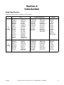
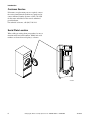

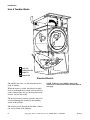
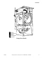

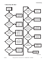
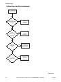
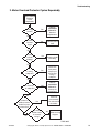

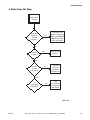
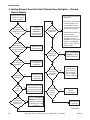

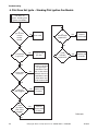
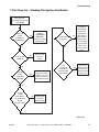
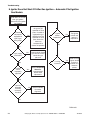
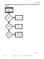
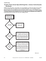
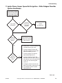
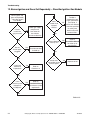
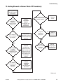

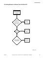
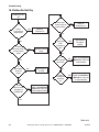


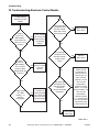
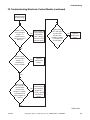
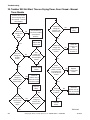
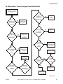

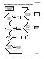
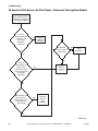

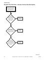
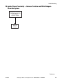
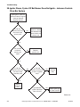

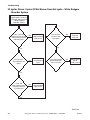
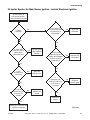
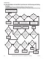
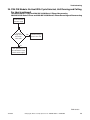

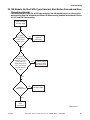
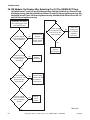


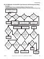
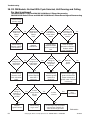

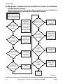
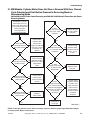


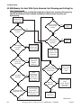


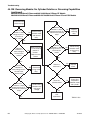
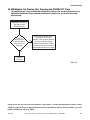


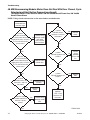
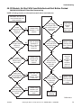


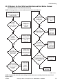


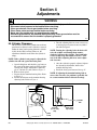
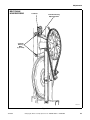


![注意!圧力鍋の蓋が飛んでやけど[PDF形式]](http://vs1.manualzilla.com/store/data/006573549_2-e5bd8bfc554b7c4e92aa9399e7d61a2d-150x150.png)