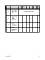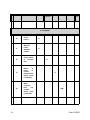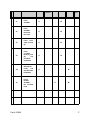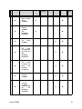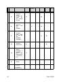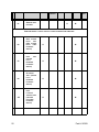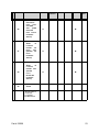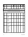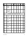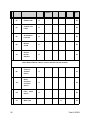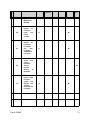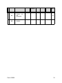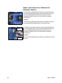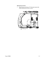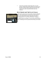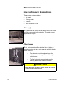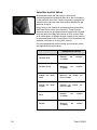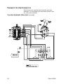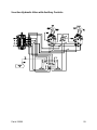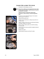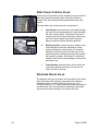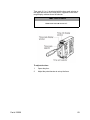
1
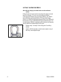
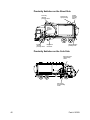
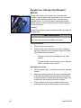
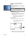
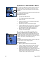
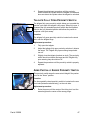
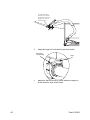
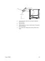
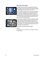
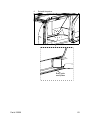
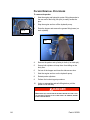
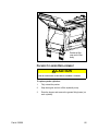
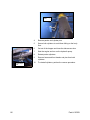
Maintenance Manual
S TAR L IGHT ™ & S UPER D UTY ™
M AINTENANCE M ANUAL
10/19/07
PART NUMBER: #90309
Table of Contents
Maintenance
Liability ..................................................................................................... 1
Warning .................................................................................................... 1
Lifting Components for Service ............................................................. 1
Lifting the Arms and Forks ........................................................ 2
Lifting the Front Body ................................................................ 2
Lifting the Entire Body ............................................................... 4
Prior to Hydraulic System Maintenance ................................................ 6
Hydraulic Settings and materials ........................................................... 7
System Settings: ....................................................................... 7
Welding Information ................................................................................ 7
Lubrication ............................................................................................... 8
Centralized Grease Block ......................................................... 9
Packer Rails Lubrication ......................................................... 10
Maintenance Checklist .......................................................................... 11
Electrical System ................................................................................... 34
Electrical Schematics .............................................................. 34
How the Electrical System Works ........................................... 34
Control Panel (located centrally in the cab) ................................ 34
Relay Box (located in the cab) .................................................... 35
Electronic Controller .................................................................... 35
Proximity Switches ...................................................................... 36
Harnesses ................................................................................... 36
Part #: 90309
iii
Adjusting and Repairing Electrical Components ............................... 36
Circuit Breakers and Fuses ..................................................... 37
Fuses .......................................................................................... 37
Manual Reset Circuit Breakers ................................................... 37
Adjusting the Proximity/Limit Switch Settings ......................... 39
Proximity Switches on the Street Side ........................................ 40
Proximity Switches on the Curb Side .......................................... 40
Lever Arm Limit Switches ....................................................... 41
Proximity Switch Gap Adjustment ........................................... 41
Packer Fully Retracted Proximity Switch ................................ 42
Packer Fully Extended Proximity Switch ................................. 43
Side Access Door Limit Switch ............................................... 45
Top Door Fully Open Proximity Switch ................................... 46
Tailgate Unlocked Proximity Switch ........................................ 46
Tailgate Fully Open Proximity Switch ..................................... 47
Arms Partially Raised Proximity Switch .................................. 47
Arms and Forks Fully Retracted Proximity Switch ................. 50
Body Raised Limit Switch (optional) ....................................... 53
Pneumatic System ................................................................................ 54
How the Pneumatic System Works ......................................... 54
Air supply .................................................................................... 54
Filter System ............................................................................... 54
In-Line Lubricator (optional) ........................................................ 55
Controls ....................................................................................... 55
Outside Controls ......................................................................... 55
iv
Part #: 90309
Valve Box and Air Valves ............................................................ 56
Air Actuators ............................................................................... 57
Central Air Drain Cocks (optional) .............................................. 57
Pneumatic System Schematics .............................................. 58
Hydraulic System .................................................................................. 60
Hydraulic Oil Tank ................................................................... 60
Return Line Filter .................................................................... 61
Return Line Filter element ....................................................... 61
Routine Maintenance .............................................................. 61
Element Replacement Procedure ........................................... 62
Hydraulic Oil ............................................................................ 63
Recommended Lubricant ............................................................ 63
Hydraulic Pump ....................................................................... 63
Directional Control Valve ........................................................ 64
Pressure Relief Valve ............................................................. 64
Work Circuits ........................................................................... 65
Arms Up Deceleration Valve ................................................... 65
Pack Circuit Dump Valve ........................................................ 67
Pressure Switch ...................................................................... 67
Pressure Switch Adjustment ....................................................... 67
Timer Adjustment ........................................................................ 68
Tailgate Lock Valve ................................................................. 70
Service Hoist (optional) ........................................................... 71
Arms Down Work Section ....................................................... 72
Part #: 90309
v
Arms Down Deceleration Valve (optional) .............................. 72
Main System Pressure Adjustment ......................................... 74
Commercial Front Loader ........................................................... 74
Hydraulic Hose ........................................................................ 75
Hydraulic System Schematics ................................................ 76
Packer Maintenance .............................................................................. 80
Packer Wear Plates Replacement .......................................... 80
Body Guide Wear Plates Replacement .................................. 82
Packer Removal Procedure .................................................... 84
Packer Cylinder Replacement ................................................ 85
vi
Part #: 90309
MAINTENANCE
LIABILITY
Labrie Environmental Group assumes no liability for any
incidental, consequential or other liability from the use of this
information. All risks and damages, incidental or otherwise,
arising from use or misuse of the information contained herein
are entirely the responsibility of the user. Although careful
precaution has been taken in the preparation of this material, we
assume no responsibility for errors or omissions.
WARNING
Prior to using your new STARLIGHT™ or SUPERDUTY™ Front
Loader, it MUST BE COMPLETELY LUBRICATED as shown on
the lube decal located near the rear of the body on the
passenger side. (Also see Lubrication section in the
Maintenance Checklist).
Initial lubrication carried out by Labrie Environmental Group is
sufficient for production and transport purposes ONLY!
With your safety in mind, we would like to remind you that ONLY
QUALIFIED PERSONNEL should service the hydraulic,
electrical, and pneumatic systems on your refuse vehicle. In
addition, these mechanics should be fully versed in the
operation of this unit. Please read the Operator Manual, prior to
attempting any maintenance of your Wittke Front Loader.
LIFTING COMPONENTS FOR SERVICE
Lifting components of the WITTKE requires special attention to
safety.
Before attempting these lifts:
Part #: 90309
•
Empty the body.
•
Chock both the front and rear wheels.
•
Stand clear of any cranes or similar lifting devices
when doing any lifts.
•
Do not stand or walk under a load that is suspended
unless there are additional safety blocking devices
in place.
1
While Labrie Environmental Group has included the
specifications of the lift equipment we use, these specifications
are intended as guides only. It is your responsability to ensure
your lift equipment meets all safety standards and that only
qualified personnel attempt these lifts.
LIFTING THE ARMS AND FORKS
You may need to lift the arms and forks manually. If you need to
do this, remember:
•
If the forks cylinders are removed or disconnected,
the forks can rotate freely – tie each fork to the arms
before lifting the arms and forks assembly.
•
Place a lift sling rated to 6400 lbs (2903 kgs) in the
middle of the fork pivot tube.
•
Complete job, reconnect.
•
Keep the sling in place while you repressurize the
system.
CAUTION
IF BOTH ARM CYLINDERS ARE REPLACED, MOVE THE JOYSTICK BACK
AND FORTH IN GRADUALLY INCREASING INCREMENTS. THIS WILL
DISTRIBUTE THE OIL EVENLY WITHIN THE CYLINDERS AND PREVENT
THE ARMS FROM FALLING.
LIFTING THE FRONT BODY
Lifting the front body may be required when you need to
complete repairs.
You will need:
•
A 18000-lb (8165 kgs) overhead crane
•
Two lift slings rated to 6000 lbs (2722 kgs)
•
A 12000-lb (5443 kgs) lift beam
To raise the front body:
1.
2
Raise the arms until they are resting on the rubber arm
stops on the sides of the body (stowed position) and
completely retract the forks against the arms.
Part #: 90309
Outer grease
fitting
2.
Remove the both outer grease fittings located on each
side of the arm pivot tube. That way, you won’t damage
the grease fittings or the lifting straps.
3.
Securely attach the slings to the lift beam, which was
previoulsy installed on the overhead crane.
4.
Wrap a lift sling around each end of the arm pivot tube.
5.
Unlatch the body latches (one on each side).
CAUTION
MAKE SURE THAT THERE IS ENOUGH CLEARANCE BEFORE LIFTING
Lift sling
THE BODY.
6.
Raise the front body. Do not raise the front body more
than 28 inches high.
7.
Install proper safety props before performing maintenance
under a lifted body.
DANGER
ALWAYS USE PROPER LIFTING DEVICES AND SAFETY PROPS BEFORE
PERFORMING ANY MAINTENANCE TASK UNDER A LIFTED BODY.
FAILURE TO DO SO MAY RESULT IN SEVERE INJURY OR EVEN DEATH.
Part #: 90309
3
LIFTING THE ENTIRE BODY
Note:All the ratings provided below are the minimum
values.
Lifting the WITTKE body requires securing both ends, front and
rear, to a lift beam. To do so, you will need two 3000-lb
(1361 kgs) rated slings (rear, see picture below), two 3000-lb
rated shackles (rear), two 6000-lb (2722 kgs) rated slings
(front), one 12000-lb (5443 kgs) lift beam (front), one 6000-lb lift
beam (rear) and one 18000-lb (8165 kgs) overhead crane. You
can also use a 12000-lb overhead crane at the front of the body
and one 6000-lb overhead crane at the rear.
Shackle
4
1.
Perform step 1 to step 5 of the Lifting the Front Body
section.
2.
Install a 3000-lb shackle on both holes located on top of
the body, near tailgate hinges.
Part #: 90309
Sling
Lift
beam
Install shackle here
Part #: 90309
3.
Fasten shackles securely on each 3000-lb lift sling.
4.
Securely attach the slings to the 6000-lb lift beam, which
was previoulsy installed on the overhead crane.
5.
Lift the body. Make sure to raise both ends of the body at
the same time.
5
PRIOR TO HYDRAULIC SYSTEM
MAINTENANCE
As with all hydraulic systems, it may be necessary to
periodically check and adjust the pressure relief settings. It may
be that a major hydraulic component has been changed, the
unit is not performing in terms of payload, or the unit has
recently been put into service and the system requires
adjustment following a run-in period.
CAUTION
FOLLOW A PROPER LOCKOUT/TAGOUT PROCEDURE PRIOR TO
SERVICING THE HYDRAULICS. DEATH OR SERIOUS INJURY CAN
RESULT. REFER TO THE OPERATOR MANUAL FOR MORE
INFORMATION ON SAFETY AND LOCKOUT/TAGOUT PROCEDURE.
Caution:
6
•
The mechanic must have previous hydraulic knowledge as
serious injury or death can result from following improper
procedures.
•
Human skin can be easily penetrated by high pressure oil
(2000 psi and above). Failure to take appropriate safety
precautions may result in serious injury or death.
•
Also, there are extreme overhead dangers if equipment is
not properly supported when servicing areas on the
hydraulic system.
Part #: 90309
HYDRAULIC SETTINGS AND MATERIALS
SYSTEM SETTINGS:
MAIN
RELIEF
PRESSURE
VALVE
DOWN
PRESSURE
1500 RPM
2750 PSI
AT
(SUPERDUTY™)
1500 RPM
(AT
1500 RPM)
ARMS
2500 PSI
AT
(STARLIGHT™)
PORT
1000 PSI
RELIEF
VALVE
PRESSURE SWITCH IN
PACK CIRCUIT
2350 PSI
AT
(STARLIGHT™)
1500 RPM
2600 PSI
AT
(SUPERDUTY™)
1500 RPM
1500 RPM
THROTTLE ADVANCE
WELDING INFORMATION
CAUTION
DISCONNECT ALL BATTERIES AND ELECTRONIC MODULES PRIOR TO
WELDING ON PACKER BODY.
CAUTION
REMOVE PAINT BEFORE WELDING OR HEATING. DO NOT WELD NEAR
LINES THAT ARE PRESSURIZED OR CONTAIN FLAMMABLE FLUID.
Part #: 90309
7
LUBRICATION
LUBRICATE, LUBRICATE, LUBRICATE! Insufficient lubrication
is a major cause of component failure. The Wittke front laoders,
like most equipment, have numerous points that require grease.
Refer to the lubrication chart located on the side of the truck for
a complete list of lube locations and the frequency they should
be greased.
# 120557
8
Part #: 90309
CENTRALIZED GREASE BLOCK
Pins at the packer end of the cylinders are remotely greased via
two grease fittings on the curb side front of the packer. Pins at
the front header end of the cylinders must be greased manually.
Packer
Grease fittings
Grease fittings
(view from inside
the hopper)
Part #: 90309
9
PACKER RAILS LUBRICATION
Lubricant
spray
It is very important to lubricate packer rails, mainly on the
packing stroke area, in order to ensure their good condition. A
lubricant spray is provided with the truck (at back of the packer)
to perform this task.
Spray all lubricant on
both rails (mainly on
the packing stroke
area)
Lubricant
spray
10
Part #: 90309
MAINTENANCE CHECKLIST
ITEM
DESCRIPTION
PRE-TRIP
AT
LANDFILL
DAILY
WEEKLY
MONTHLY
1000
HRS
1. LUBRICATION
PACKER
1
CYLINDER PINS
X
(4)
2
ARM CYLINDER
(2) AND
PIVOTS (2)
PINS
ARM
3
X
PIVOT
TUBE COLLARS
X
(8)
FORK
4
CYLINDER PINS
X
(4)
FORK
5
PIVOT
TUBE COLLARS
X
(2)
Part #: 90309
11
ITEM
6
DESCRIPTION
PRE-TRIP
TAILGATE
HINGE PINS
(2)
AT
LANDFILL
DAILY
WEEKLY
MONTHLY
1000
HRS
X
TAILGATE
7
CYLINDER PINS
(2)
AND
PIVOTS
X
(2)
TAILGATE
8
LATCH ROLLER
PINS
*9
*10
X
(2)
REAR
BODY
HINGE PINS
(2)
SIDE
ACCESS
DOOR
HINGES
X
X
(2)
CLEANOUT
*11
DOOR
HINGES
X
(2)
PUMP
**12
12
DRIVE-LINE
U-JOINTS AND
SLIP YOKE (3)
X
Part #: 90309
ITEM
DESCRIPTION
TAG
*13
PRE-TRIP
AT
LANDFILL
DAILY
WEEKLY
MONTHLY
1000
HRS
AND/OR
PUSHER
(QTY
AXLE
MAY
CONSULT MANUFACTURER
VARY)
INSPECT
LEAKS
*14
FOR
IN
X
PACKER
REMOTE
GREASE LINES
INSPECT
15
HYDRAULIC OIL
X
LEVEL IN TANK
*Denotes option or
not all units
**Unit may be fitted
with a driveline which
does not require
grease
Part #: 90309
13
ITEM
DESCRIPTION
PRE-TRIP
AT
LANDFILL
DAILY
WEEKLY
MONTHLY
1000
HRS
2. CLEANING
16
SAFETY
O
LABELS
MIRRORS,
17
LAMPS,
O
WINDOWS,
CAMERA
CLEAN DEBRIS
18
AT
TAILGATE
O
SEAL
19
DEBRIS
IN
FRONT
OF
PACKER,
INSIDE HOPPER
O
(MORE OFTEN
IF REQUIRED)
WASH
COMPLETE
20
BODY
AND
CHASSIS
O/M
(MORE OFTEN
IF REQUIRED)
14
Part #: 90309
ITEM
21
DESCRIPTION
PRE-TRIP
AT
LANDFILL
DAILY
WEEKLY
PRE-TRIP
AT
LANDFILL
DAILY
WEEKLY
MONTHLY
1000
HRS
OTHER:
*DENOTES OPTION OR
NOT ALL UNITS
O = OPERATOR
M = MAINTENANCE
ITEM
DESCRIPTION
MONTHLY
1000
HRS
3. MECHANICAL INSPECTION (TRUCK AT REST)
INSPECT FOR DISTORSION, CRACKS, AND/OR UNUSUAL WEAR. ENSURE MOUNTING AND PIN RETAINER
BOLTS ARE INTACT AND TIGHT.
BODY MOUNTS
(2)
AND
*22
RELATED
NUTS,
O
M
O
M
BOLTS
AND SPRINGS
*23
BODY
HINGE
EARS
(2), PIN
(1)
AND
RETAINING
HARDWARE
SERVICE HOIST
CYLINDER
*24
EARS
(4), PINS
(4),
AND
O
M
RETAINING
HARDWARE
Part #: 90309
15
ITEM
DESCRIPTION
PRE-TRIP
AT
LANDFILL
DAILY
WEEKLY
MONTHLY
1000
HRS
SERVICE HOIST
CYLINDER
*25
MOUNTING
ON
BOLTS
CHASSIS
O
M
O
M
(QTY.
VARIES)
SERVICE HOIST
*26
SAFETY
PROP
AND
PROP
SOCKETS
(INSPECT
PRIOR USING)
ARM
27
ASSEMBLIES
O
M
O
M
O
M
O
M
(2)
ARM
ASSEMBLY
28
MOUNTING
BOLTS,
LOCK
WASHERS AND
NUTS
29
(12)
ARM
PIVOT
TUBE
(1) AND
PIVOT
TUBE
COLLARS
(2)
ARM CYLINDER
(4), PINS
(4),
AND
EARS
30
RETAINING
HARDWARE
16
Part #: 90309
ITEM
31
DESCRIPTION
FORK
ASSEMBLY
PRE-TRIP
AT
LANDFILL
DAILY
WEEKLY
O
M
O
M
O
M
O
M
MONTHLY
1000
HRS
FORK
32
ASSEMBLY
MOUNTING
BOLTS
(4)
FORK
33
PIVOT
TUBE COLLARS
(2)
FORK
CYLINDER
34
EARS
(4), PINS
(4),
AND
RETAINING
HARDWARE
RESIDENTIAL
*35
CARRY
CAN
AND MOUNTING
O
M
HARDWARE
FRONT
HEADER
36
ASSEMBLY
O
M
INC. CYLINDER
EARS
Part #: 90309
17
ITEM
DESCRIPTION
PRE-TRIP
AT
LANDFILL
DAILY
WEEKLY
MONTHLY
1000
HRS
PACKER
37
ASSEMBLY
INC. CYLINDER
O
M
EARS
PACKER
CYLINDER PINS
38
(4),
AND
O
M
RETAINING
NUTS/BOLTS
PACKER
39
GUIDE,
RAILS
AND
WEAR
O
M
SHOES
INTERIOR
OF
AND
HOPPER
40
MAIN
BODY
O
M
O
M
WALLS, FLOOR
AND TOP DOOR
EXTERIOR
HOPPER
41
MAIN
OF
AND
BODY
WALLS, FLOOR
AND TOP DOOR
18
Part #: 90309
ITEM
DESCRIPTION
SIDE
42
PRE-TRIP
AT
LANDFILL
DAILY
WEEKLY
MONTHLY
1000
HRS
ACCESS
DOOR
O
M
O
M
ASSEMBLY
CANOPY
ASSEMBLY
43
AND
EXTENSION
HARDWARE
44
TOP
DOOR
ASSEMBLY
TOP
O
M
O
M
O
M
O
M
O
M
DOOR
CYLINDER PINS
45
(2), EARS (2),
AND
RETAINING
HARDWARE
TOP
DOOR
U
CYLINDER
46
BOLT
AND
RELATED
NUTS/BOLTS
47
TAILGATE
ASSEMBLY
TAILGATE
CYLINDER
48
EARS
(4), PINS
(4),
AND
RETAINING
HARDWARE
Part #: 90309
19
ITEM
DESCRIPTION
PRE-TRIP
AT
LANDFILL
DAILY
WEEKLY
MONTHLY
1000
HRS
TAILGATE
LATCH
49
(2),
(2),
ASSEMBLY
PIVOTS
AND
PINS
O
M
ROLLER
(2)
TAILGATE
50
SEAL
AND
O
SEAL
M
RETAINER
TAILGATE
HINGE
51
EARS
(2), PINS (2),
O
AND
M
RETAINING
HARDWARE
*52
TAILGATE
SAFETY PROP
O
M
SAFETY
EQUIPMENT
IS
PRESENT?
*53
(E.G.
FIRE
O
EXTENGUISHER
, FIRST AID KIT,
ETC.)
54
OTHER:
*Denotes option or
not all units
O = Operator
M = Maintenance
20
Part #: 90309
ITEM
DESCRIPTION
PRE-TRIP
AT
LANDFILL
DAILY
WEEKLY
MONTHLY
1000
HRS
4. OPERATION (MAIN CONTROLS)
OBSERVE TRAVEL IS SMOOTH AND EVEN, SPEED IS NORMAL, CONTROLS ARE RESPONSIVE.
55
56
UP/
FORKS
DOWN
UP/
ARMS
DOWN
O
M
O
M
O
M
O
M
O
M
O
M
PACKER PACK/
57
RETURN/
AUTOPACK/
AUTOSTOP
FOLLOWER
58
PACK/RETURN/
AUTOPACK/
AUTOSTOP
HOPPER
59
DOOR
TOP
OPEN/
CLOSE
60
Part #: 90309
TAILGATE
OPEN/CLOSE
21
ITEM
61
DESCRIPTION
PRE-TRIP
SERVICE HOIST
AT
LANDFILL
DAILY
WEEKLY
MONTHLY
O
UP/DOWN
1000
HRS
M
PERFORM SAFETY LOCKOUT TESTS TO CHECK PROXIMITY/LIMIT SWITCHES
SIDE
ACCESS
DOOR
62
TEST
(SIDE ACCESS
LIMIT/
DOOR
O
M
O
M
O
M
O
M
PROXIMITY
SWITCH)
PACK
TEST
(PACKER
63
FULLY
EXTENDED
PROXIMITY
SWITCH)
AUTOPACK
(PACKER
TEST
64
FULLY
EXTENDED
PROXIMITY
SWITCH)
PACK
LOCKOUT/
TAILGATE TEST
*65
(TAILGATE
UNLOCKED
PROXIMITY
SWITCH)
22
Part #: 90309
ITEM
DESCRIPTION
PRE-TRIP
AT
LANDFILL
DAILY
WEEKLY
MONTHLY
1000
HRS
PACK/AUTOLOCK-
PACK
OUT/ARMS
66
TEST
(ARMS
ELEVATED
O
M
O
M
O
M
PACK CUTOUT
PROXIMITY
SWITCH)
ARMS
UP
LOCKOUT/
HOPPER
67
DOOR
TOP
TEST
(HOPPER TOP
DOOR
PROXIMITY
SWITCH)
ARMS
UP
LOCKOUT/
PACKER
68
TEST
(PACKER
FULLY
RETRACTED
PROXIMITY
SWITCH)
69
OTHER
*Denotes option or
not all units
O = Operator
M = Maintenance
Part #: 90309
23
ITEM
DESCRIPTION
PRE-TRIP
AT
LANDFILL
DAILY
WEEKLY
MONTHLY
1000
HRS
5. OPERATION (MISC. CONTROLS AND FEATURES)
CHECK CONTROL CONSOLE WARNING DEVICES ARE FUNCTIONNING.
70
PUMP SWITCH
LAMP
O
M
O
M
O
M
O
M
O
M
PACKER
71
WARNING
LAMP
HOPPER
72
TOP
DOOR
WARNING
LAMP
ACCESS DOOR
73
WARNING
LAMP
TAILGATE
UNLOCKED
WARNING
LAMP/
74
EXTERNAL
ALARM
(TAILGATE
UNLOCKED
PROXIMITY
SWITCH)
24
Part #: 90309
ITEM
DESCRIPTION
PRE-TRIP
AT
LANDFILL
DAILY
WEEKLY
MONTHLY
1000
HRS
ARMS
75
ELEVATED
O
WARNING
O
M
LAMP
SERVICE HOIST
*76
BODY
RAISED
O
WARNING
M
LAMP/BUZZER
CHECK EXTERNAL LAMPS AND MISCELLANEOUS ARE FUNCTIONING
*77
AUXILIARY
CONTROLS
O
M
O
M
O
M
O
M
O
M
O
M
STOP, SIGNAL
78
AND
TAIL
LAMPS
79
80
81
82
Part #: 90309
MARKER
LAMPS
HOPPER LAMP
BACKUP
LAMPS
BACKUP
FLOOD LAMPS
25
ITEM
83
84
85
86
DESCRIPTION
STROBE LAMP
CAMERA DUAL
LAMPS
ALTERNATING
FLASHERS
BACKUP
ALARM
PRE-TRIP
AT
LANDFILL
DAILY
WEEKLY
MONTHLY
1000
HRS
O
M
O
M
O
M
O
M
O
M
GLOBAL
*87
MOTION
SENSORS
CHECK MISCELLANEOUS CONTROL CONSOLE DEVICES ARE FUNCTIONNING
THROTTLE
88
ADVANCE
O
M
O
M
O
M
SWITCH
ARMS
*89
ACTIVATED
AUTOPACK
SWITCH
*90
*91
26
FORK
WIDTH
SWITCH
WASH TANK
O
M
Part #: 90309
ITEM
92
DESCRIPTION
PRE-TRIP
AT
LANDFILL
DAILY
WEEKLY
MONTHLY
1000
HRS
PRE-TRIP
AT
LANDFILL
DAILY
WEEKLY
MONTHLY
1000
HRS
OTHER:
*Denotes option or
not all units
O = Operator
M = Maintenance
ITEM
DESCRIPTION
6. HYDRAULIC SYSTEM
HYDRAULIC
OIL TANK:
CHECK
93
FOR
LEAKS,
DAMAGE, ETC.
O
M
ON TANK
CHECK
IS
94
TANK
SECURELY
MOUNTED
O
TO
M
CHASSIS
FRAME
CHECK
OIL
LEVEL IN TANK
95
(ALL
O
M
CYLINDERS
RETRACTED)
Part #: 90309
27
ITEM
96
97
DESCRIPTION
CHECK
PRE-TRIP
OIL
CONDITION
O
AT
LANDFILL
DAILY
WEEKLY
MONTHLY
1000
HRS
M
REPLACE OIL
(MORE OFTEN
IF REQUIRED)
M
CHECK
98
SUCTION BALL
IS
VALVE
O
M
FULLY OPEN
CLEAN
THE
BREATHER
99
CAP
(REPLACE
M
IF NECESSARY)
(MORE OFTEN
IF REQUIRED)
CLEAN
SUCTION
STRAINER
WITH VARSOL/
100
M
COMPRESSED
AIR
IF
(REPLACE
DAMAGED)
(MORE OFTEN
IF REQUIRED)
TO PROTECT THE HYDRAULIC COMPONENTS OF YOUR NEW EQUIPMENT, THE RETURN LINE FILTER
MUST BE CHANGED AFTER THE 50 FIRST HOURS OF USE. THEREUPON, THE FILTER
SHOULD BE CHANGED ONCE EVERY 1000 HOURS OR FOLLOWING A MAJOR HYDRAULIC COMPONENT
FAILURE.
28
Part #: 90309
ITEM
DESCRIPTION
PRE-TRIP
AT
LANDFILL
DAILY
WEEKLY
MONTHLY
1000
HRS
CHANGE
HYDRAULIC
101
LINE
RETURN
M (NEW UNIT)
FILTER
OIL
M
(MORE OFTEN
IF REQUIRED)
CLEAN
MAGNETIC
102
PLUG
(MORE
M
IF
OFTEN
REQUIRED)
PUMP:
103
INSPECT PUMP
FOR LEAKS
O
M
ENSURE PUMP
104
IS
O
SECURELY
M
MOUNTED
ENSURE
105
DRIVELINE
IS
M
SECURELY
MOUNTED
HYDRAULIC
VALVE
BANK:
INSPECT
106
VALVE
BANK
O
M
FOR LEAKS
Part #: 90309
29
ITEM
DESCRIPTION
PRE-TRIP
AT
LANDFILL
DAILY
WEEKLY
MONTHLY
1000
HRS
ENSURE
107
VALVE BANK IS
SECURELY
O
M
MOUNTED
CHECK
SYSTEM
PRESSURE
RELIEF
VALVE(S)
108
SETTINGS.
ADJUST
IF
M
REQUIRED.
(USE
PRESSURE
GAUGE.
RECORD.)
CHECK
ARMS
DOWN
PRESSURE
RELIEF
VALVE
SETTINGS.
*109
ADJUST
IF
M
REQUIRED.
(USE
PRESSURE
GAUGE.
RECORD.)
30
Part #: 90309
ITEM
DESCRIPTION
PRE-TRIP
AT
LANDFILL
DAILY
WEEKLY
MONTHLY
1000
HRS
MISCELLANEOUS:
INSPECT
ALL
HYDRAULIC
110
FOR
LINES
O
M
O
M
LEAKS,
CHAFING
INSPECT
ALL
HYDRAULIC
CYLINDERS
111
AND
MISC.
HYDRAULIC
COMPONENTS
FOR LEAKS
CHECK
PACK
CIRCUIT
PRESSURE
112
M
SWITCH
SETTING.
ADJUST
IF
REQUIRED.
INSPECT ARMS
UP/DOWN
*113
CAM(S)
ARE
SECURE
AND
O
M
TRIPPING
DECELERATION
VALVES(S)
Part #: 90309
31
ITEM
114
DESCRIPTION
PRE-TRIP
AT
LANDFILL
DAILY
WEEKLY
MONTHLY
1000
HRS
PRE-TRIP
AT
LANDFILL
DAILY
WEEKLY
MONTHLY
1000
HRS
OTHER:
*Denotes option or
not all units
O = Operator
M = Maintenance
ITEM
DESCRIPTION
7. PNEUMATIC SYSTEM
DRAIN
115
AIR
TANKS (AT THE
END OF EACH
O
DAY)
INSPECT
116
LINES
AIR
FOR
O
M
LEAKS
REPLACE
117
AIR
FILTER
M
ELEMENT
REPLACE MIST
118
SEPARATOR
M
ELEMENT
32
Part #: 90309
ITEM
DESCRIPTION
LIGHTLY
119
AIR
PRE-TRIP
AT
LANDFILL
DAILY
WEEKLY
MONTHLY
1000
HRS
OIL
M
ACTUATORS
120
Part #: 90309
OTHERS:
33
ELECTRICAL SYSTEM
The electrical system is divided into two sections. The first
section describes how the electrical components work and the
second section describes how to adjust and repair the electrical
components.
Wittke offers two different electrical systems. One is controlled
by relay logic and the other one is controlled by an electronic
controller (optional). Both systems are equivalent. The only
difference between both of them is the control box located inside
the cab.
ELECTRICAL SCHEMATICS
Two types of schematics are provided with Wittke trucks. First,
there is the electrical schematic, which shows how components
are wired to each other. This schematic is useful to diagnose
electrical circuits.
The second one is the control schematic, which shows the truck
logic. This schematic is used to find which components are
involved in a specific circuit. If the truck is equipped with an
electronic controller, this schematic is replaced by a
configuration sheet, which is explained in details in the
Electronic Modules Troubleshooting Guide (part # 90330).
HOW THE ELECTRICAL SYSTEM WORKS
The electrical system includes:
•
Control panel
•
Relay box
•
Electronic controller (optional)
•
Valve box
•
Limit/proximity switches
•
Harnesses
Control Panel (located centrally in the cab)
The front loader’s push buttons, toggle switches and warning
lamps are located in a centrally mounted control panel in the
cab. Some units have auxiliary controls located on the curb or
street side of the truck.
34
Part #: 90309
Relay Box (located in the cab)
The relay logic consists of a control system made up with
traditional relays. To troubleshoot such a system, please refer to
the electrical schematic provided with the truck and use the
appropriate tools.
•
Main relay: A high current relay centralizes power
to the relay box in the cab.
•
Circuit breakers: Manual reset breakers protect
systems from excessive current.
•
Relays: A relay is a series of switches influenced by
a common coil but controlled from a remote location,
such as a proximity switch.
•
Diodes: Diodes ensure the current conducts in one
direction only.
•
Timer: The timer is a relay switch used to delay the
return of the packer once it has completed a pack
cycle. It is wired in the pack system and is set to
2 seconds. If the truck is equipped with an electronic
controller, it is not possible to adjust the delay, which
is also set, in this case, to 2 sec.
Electronic Controller
Some trucks are equipped with an electronic controller, making
the truck more reliable by reducing the number of wires and
components. Electrical maintenance is different from relay logic.
The use of an electronic controller enables LabriePlus to
perform remote troubleshooting, which facilitates the debugging
process. Labrie Environmental Group offers training on this
technology. To know more about electronic controllers and
training schedule, please call LabriePlus.
Part #: 90309
35
Proximity Switches
Body-mounted proximity switches control the packer operation
and provide the means for safety lockouts.
Harnesses
Harnesses connect all electrical components. They are generic
and may contain wires and plugs that are not used.
ADJUSTING AND REPAIRING ELECTRICAL
COMPONENTS
The required electrical system adjustments include:
36
•
Circuit Breakers and Fuses
•
Adjusting the Proximity Switch Settings
•
Packer Fully Retracted Proximity Switch
•
Packer Fully Extended Proximity Switch
•
Side Access Door Limit/Proximity Switch
•
Top Door Fully Open Proximity Switch
•
Tailgate Unlocked Proximity Switch
•
Tailgate Fully Open Proximity Switch
•
Arms Fully Retracted Proximity Switch
•
Arms Partially Raised Proximity Switch
•
Forks Fully Retracted Proximity Switch
•
Body Raised Limit Switch
Part #: 90309
CIRCUIT BREAKERS AND FUSES
Power for the Wittke front loaders’ electrical system is protected
by two 30 A fuses and up to five manual reset circuit breakers
(depending on the options).
Fuses
FUNCTION
AMPS
LOCATION
MAIN
BATTERY
POWER (2)
30
FITTED IN THE BATTERY BOX
AMPS
TO
EACH
POWER SUPPLY
PROTECT
RELAY
BOX
Manual Reset Circuit Breakers
Push the in-cab relay box’s circuit breaker button to reset these
circuits.
CAUTION
NEVER HOLD A CIRCUIT BREAKER BUTTON DOWN WHEN IT REFUSES
TO RESET. SEVERE ELECTRICAL DAMAGE MAY RESULT. REPORT
THIS TO YOUR SUPERVISOR AND MAINTENANCE DEPARTMENT.
?
Part #: 90309
Note:Consult the OEM manual for information on
equipment not manufactured by Labrie
Environmental Group.
37
FUNCTION
AMPS
LOCATION
MAIN
CONTROL
10
CIRCUIT
AMPS
IN-CAB RELAY BOX
(F2)
PROXIMITY/
LIMIT
SWITCH
SENSORS
10
AMPS
IN-CAB RELAY BOX
(F1)
HOPPER/
MIRROR
LAMP
SWITCHES
10
AMPS
IN-CAB RELAY BOX
(F3)
MONITOR
(F4)
STROBE
LAMP/
ALTERNATING
FLASH-
ING LIGHTS/
10
AMPS
IN-CAB RELAY BOX
15
AMPS
IN-CAB RELAY BOX
BACKUP
(F5)
LIGHTS
38
Part #: 90309
ADJUSTING THE PROXIMITY/LIMIT SWITCH
SETTINGS
Proximity/limit switches act as remote electrical on/off switches.
CAUTION
PROXIMITY/LIMIT SWITCHES MUST FUNCTION PROPERLY. SERIOUS
DAMAGE OR DEATH MAY RESULT IF YOU OPERATE THE FRONT
LAODER WITH IMPROPERLY ADJUSTED PROXIMITY SWITCHES.
Part #: 90309
39
Proximity Switches on the Street Side
Forks fully
retracted
proximity switch
Tailgate
fully open
proximity
switch
Top Door fully
open proximity
Packer
proximity
switches
(2)
Arm fully
retracted
proximity switch
Tailgate unlocked
proximity switch
Body raised
limit switch
Proximity Switches on the Curb Side
Side access door
limit/proximity
switch
Arm partially
raised proximity
switch
40
Part #: 90309
LEVER ARM LIMIT SWITCHES
General adjustment procedure:
1.
Loosen limit switch nut.
2.
Move lever arm to approximate position where limit switch
is to trip.
3.
Tighten nut.
4.
To fine tune limit switch, loosen nut slightly.
5.
With a flathead screwdriver, turn the adjusting screw
located at the center of the nut until a click is heard.
6.
Tighten the nut.
7.
Test operation; repeat steps 1 to 7 if necessary.
PROXIMITY SWITCH GAP ADJUSTMENT
Once the proximity switch is positioned correctly (see
procedures below), make sure that the gap between the target
and the proximity switch is sufficient.
General gap adjustment procedure:
Part #: 90309
1.
Loosen the proximity switch nuts.
2.
Adjust the proximity switch so there is a gap of 3/8 inch
(9.5 mm) between it and the target.
3.
Tighten the nuts.
4.
Test operation to make sure the proximity switch light
comes on when the target is detected and the proximity
switch itself works properly.
41
PACKER FULLY RETRACTED PROXIMITY
SWITCH
This proximity switch locks out the Arms up function and
activates a warning lamps when the packer is not in the “home”
position and also stops the packer when it reaches its fully
retracted position. It is very important to adjust this proximity
switch properly in order to avoid the packer hitting the hopper at
the end of its stroke.
Location:
This proximity switch is mounted on the front wall of the body, on
the street side.
IMPORTANT
THIS PROCEDURE MUST BE PERFORMED BY TWO PEOPLE.
Testing procedure:
1.
Empty all refuse from the body.
2.
Initiate a Pack cycle and observe the “home” position of
the packer when the cycles completes. Adjust the Packer
fully retracted proximity switch if:
•
The packer stops before reaching the fully “home”
position.
•
The pack cylinders remain pressured up or abruptly
bottom out at the “home” position.
Adjustment procedure:
42
1.
Move the packer about 1 inch back from the fully retracted
position.
2.
Adjust the proximity switch so it is active (the amber light
on the proximity switch should be ON) when the packer
reaches this position. Ideally, there should be a gap of 3/8
inch between the proximity switch and its target.
3.
Test the packer for a full cycle. Ensure that there is no
knocking noise at the end of the packer cylinder stroke.
Part #: 90309
PACKER FULLY EXTENDED PROXIMITY
SWITCH
This proximity switch stops the packer when it reaches its fully
extended position (pack cycle).
This proximity switch is mounted on the front wall of the body, on
the street side.
IMPORTANT
THIS PROCEDURE MUST BE PERFORMED BY TWO PEOPLE.
Testing procedure:
1.
Empty all refuse from the body.
2.
Initiate a pack cycle and observe the fully extended
position of the packer. Adjust the Packer fully extended
proximity switch if:
•
The packer stops before or after reaching the fully
extended position (see picture below).
Adjustment procedure:
1.
Move the packer so it is aligned with the breaker bar.
Packer must be aligned with the
breaker bar
2.
Part #: 90309
Adjust the proximity switch so it is active (the amber light
on the proximity switch should be ON) when the packer
43
reaches this position. Ideally, there should be a gap of 3/8
inch between the proximity switch and its target.
3.
44
Test the packer for a full cycle.
Part #: 90309
SIDE ACCESS DOOR LIMIT SWITCH
This limit switch cuts all hydraulic power when the side access
door is not closed.
Note:Some units can be equipped with a proximity switch.
Location:
The side access door limit switch is mounted on the side door
frame.
Testing procedure:
1.
Open the side access door approximately 2 inches (5 cm)
and attempt to operate any hydraulic function. All
hydraulic functions should be disabled.
DANGER
INJURY OR DEATH MAY OCCUR IF YOU ATTEMPT TO ENTER THE BODY
WHILE THE PACKER OR ARMS ARE WORKING.
2.
Target
Part #: 90309
If all hydraulic functions are not disabled, the limit switch is
faulty and must be replaced.
Adjustment procedure:
1.
Adjust limit switch height until the target enters the limit
switch when the side access door is closed.
2.
Perform the testing procedure mentioned above.
45
TOP DOOR FULLY OPEN PROXIMITY SWITCH
The Top door fully open proximity switch controls the cutout of
the arms up function if the top door is not fully open. It also
illuminates the Top door warning lamp on the control console.
Proximity
switch
Target
Towards cab
Location:
The Top door fully open proximity switch is located on the street
side, on rear part of the top door.
Adjustment procedure:
1.
Fully open the hopper top door.
2.
Turn off the hydraulic pump and the engine.
3.
Climb on the roof.
4.
Adjust the proximity switch so it detects the target when
the top door is fully open.
5.
Start the engine and turn on the hydraulic pump.
6.
Close the hopper top door on about an inch. The proximity
switch should not detect the target and the Hopper top
door warning lamp on the console should turn off.
7.
Make sure there is a gap of 3/8 inch between the
proximity switch and the target.
TAILGATE UNLOCKED PROXIMITY SWITCH
Cylinder
head edge
The tailgate unlocked proximity switch disables the pack cycle,
illuminates the Tailgate unlocked warning lamp in the cab and
sounds the backup alarm if the tailgate is not completely closed.
In addition, this proximity switch disables packing.
Location:
The Tailgate Unlocked Proximity Switch is located on the street
side of the tailgate, near the tailgate cylinder.
Adjustment procedure:
46
1.
Make sure that the tailgate is closed and locked.
2.
Place the Tailgate unlocked proximity switch so it faces
and detects tailgate cylinder head edge. The Tailgate
unlocked warning lamp on the console should be off.
3.
Slightly open the tailgate until it is unlocked. The proximity
switch should not detect the cylinder anymore. The
Tailgate unlocked warning lamp on the console should be
on and the backup alarm should be heard.
Part #: 90309
4.
Repeat the adjustment procedure until the proximity
switch detects the cylinder when the tailgate is locked and
does not detect the cylinder when the tailgate is unlocked.
TAILGATE FULLY OPEN PROXIMITY SWITCH
Proximity
switch
target
The tailgate fully open proximity switch allows you to enable the
ejection cycle when the tailgate is fully open. When fully open, it
bypasses the fully extended proximity switch that limits packer
travel to the fully extended position and allows the packer to
complete a full eject sweep.
Location:
The tailgate fully open proximity switch is located on the street
side, near the tailgate hinge
Adjustment procedure:
1.
Fully open the tailgate.
2.
Adjust the tailgate fully open proximity switch so it detects
the target. The Tailgate fully open warning lamp should
turn on.
3.
Slightly close the tailgate (to about an inch). The proximity
switch should not detect the target and the Tailgate fully
open warning lamp should turn off.
4.
Repeat the procedure until the proximity switch is properly
adjusted.
ARMS PARTIALLY RAISED PROXIMITY SWITCH
This proximity switch stops the arms at mid-height if the packer
is not in the “home” position.
Location:
The Arms partially raised proximity switch is located on the arm
pivot tube (between cab and body), on the curb side.
Adjustment procedure:
1.
Part #: 90309
Raise the arms until the center of the forks pivot is at the
same height as the center of the canopy hinge.
47
To perform the adjustment, the center of forks
pivot must be at the same
height as the center of
the canopy hinge
0
2.
Adjust the target so it activates the proximity switch.
Arm partially
raised proximity
3.
48
Target
Make sure that the proximity switch detects the target on
all the detection zone shown below.
Part #: 90309
DETECTION ZONE
Part #: 90309
4.
Once the proximity switch and the target are adjusted,
lower the arms.
5.
Start the packer.
6.
While the packer is in motion, raise the arms. They should
stop at mid-height.
7.
If it is not the case, readjust the proximity switch and its
target.
49
ARMS AND FORKS FULLY RETRACTED
PROXIMITY SWITCH
The Arms fully retracted proximity switch ensures that the Arm
not stowed warning lamp on the console illuminate if the arms
are not completely parked. Both arms and forks must be
completely parked in order to turn off the Arm not stowed
warning lamp.
Location:
The Arms fully retracted proximity switch is located on the arm
pivot tube (between cab and body), on the street side.
Adjustment
screws
The Forks fully retracted proximity switch ensures that the Arm
not stowed warning lamp on the console illuminate if the arms
are not completely parked. Both arms and forks must be
completely parked in order to turn off the Arm not stowed
warning lamp.
Location:
Proximity
switch
50
The Forks fully retracted proximity switch is located on the street
side fork.
Part #: 90309
Adjustment procedure:
1.
Part #: 90309
Raise the arms until there is 57 3/8 inches between both
cylinder attachments (center to center).
51
2.
Adjust the target so it activates the proximity switch.
(proximity switch light on).
Arms fully
retracted
proximity switch
Target
3.
Lower the arms.
4.
Retract the forks until there is a distance of 31 inches
between both fork cylinder attachments (center to center).
31”
52
5.
Adjust the target so it activates the proximity switch
(proximity switch light on).
6.
Perform tests to see if the Arm not stowed warning lamp
reacts properly when the forks or the arms are not fully
parked.
Part #: 90309
7.
If the Arm not stowed warning lamp does not “react”
properly, readjust the proximity switches and their targets.
The Arm not stowed warning lamp should turn off only
when the arms are fully raised and the forks fully
retracted.
BODY RAISED LIMIT SWITCH (OPTIONAL)
A limit switch located on the truck chassis activates the backup
alarm, and a warning buzzer sounds as soon as the body is
about one foot above the chassis. Adjust the limit switch
accordingly (refer to “Lever Arm Limit Switches” on page 41).
This safety feature is provided to to warn people around that the
truck in unloading and to tell operator that the body is still raised.
Limit switch
Part #: 90309
53
PNEUMATIC SYSTEM
HOW THE PNEUMATIC SYSTEM WORKS
The pneumatic system includes:
•
Air supply
•
Filtering system
•
Controls
•
Valve box and air valves
•
Air Actuators
Air supply
Air is drawn from the chassis air tank, passes through an air and
mist filter system and into the valve box. The system runs at
approximately 120 psi.
Filter System
The chassis air supply is filtered before it is used in the control
circuit. Two filters are fitted on the street side. Air supply is
passed through an air filter, a mist separator and then routed to
the air valve box.
•
Filter elements should be replaced as per the
maintenance schedule guidelines at the beginning
of this chapter.
•
The filter bowls and chassis air tanks must be
manually drained daily to remove moisture.
CAUTION
POORLY MAINTAINED PNEUMATIC CONTROL SYSTEMS ARE A MAJOR
CAUSE OF PACKER CONTROL FAILURE.
54
Part #: 90309
In-Line Lubricator (optional)
Recommended for use in cold and dry climates, the optional
lubricator is fitted in line after the mist separator. It is filled with
air tool oil which is bled into the system to ensure adequate
lubrication.
Controls
Standard arms/forks control is by mean of a dual handle
joystick, mounted next to the driver.
?
Note:The arms up and main joystick’s air lines are the only
lines with a cutout valve. This cutout valve cuts air to
the joystick and to the arm up function when the
packer is not in the “home” position or when the top
door is not fully open.
Outside Controls
Auxiliary controls can be installed outside the cab, either on the
curb or street side. The Auxiliary controls switch must be in the
On position in order for the outside controls to operate.
The throttle advance switch fitted to the outside control station
will advance the engine RPM to 1500 when activated. The
transmission must be in neutral, and the engine ECM
programmed to act on the input signal.
With the throttle advance switch in the “auto” position, the
system will advance to 1500 RPM when the Pack or Return
functions are activated.
Part #: 90309
55
Valve Box and Air Valves
Mounted behind the cab, the valve box houses the
solenoid-operated air valves that direct air to the air actuators
on the hydraulic valve bank. Power is required to energize the
solenoid so air can pass to the work section dedicated to that
particular air valve.
Supply air from the chassis air tank passes through the filters
then feeds the air valves in the valve box. These normally
closed air valves are grouped into banks capped with manifold
ends with ports for supply and exhaust air to be routed. When
an air valve opens, air passes through a single air line from the
air valve and leads to one of two ports on an air actuator on the
hydraulic valve bank or to the joystick (cutout).
On units equipped with the Auto-dump, the pneumatic valves
are replaced by electrical valves.
Valve Box Air Valves
TAILGATE OPEN
TAILGATE CLOSE
THE
RETRACTS
THE
TAILGATE
CYLINDERS
DOOR CYLINDER
HOPPER TOP DOOR
CLOSED
DOOR CYLINDER
RETURN
TAILGATE
CYLINDERS
HOPPER TOP DOOR
OPEN
PACK
56
EXTENDS
RETRACTS THE HOPPER TOP
EXTENDS
EXTENDS
THE
HOPPER
THE
TOP
PACKER
CYLINDERS
RETRACTS
THE
PACKER
CYLINDERS
Part #: 90309
Valve Box Air Valves
ARMS UP CUTOUT
TIPPER UP
ARM CYLINDERS
CYCLES TIPPER ACTUATOR UP
TIPPER DOWN
MAIN
CUTS AIR USED TO RETRACT THE
JOYSTICK
CUTOUT
CYCLES
TIPPER
ACTUATOR
DOWN
DISABLES JOYSTICK OPERATION
WITH THE HYDRAULIC PUMP OFF
Air Actuators
Air from the air valves and joystick is routed to the air actuators
mounted on the hydraulic valve sections. The air actuators are
dedicated to a particular hydraulic function and influence the
direction in which the valve spool is moved. Once the air supply
is removed from the actuator, the valve spool is centered by its
spring, and the actuator returns to the neutral poisition.
Central Air Drain Cocks (optional)
A series of air drain cocks are provided on a bracket at the
battery box.
?
Part #: 90309
Note:
•
All air tanks should be drained daily
•
Be sure to drain the wet tank first.
•
Poorly maintained pneumatic control systems are a major
cause of packer control failure.
•
Your air drain cocks may differ slightly from those shown at
left.
57
PNEUMATIC SYSTEM SCHEMATICS
Each WITTKE truck is provided with its specific pneumatic
schematic. For more details on the pneumatic system of your
unit, refer to this schematic.
5-section Hydraulic Valve (w/o Auto-dump)
58
Part #: 90309
5-section Hydraulic Valve with Auxiliary Controls
Part #: 90309
59
HYDRAULIC SYSTEM
HYDRAULIC OIL TANK
The hydraulic oil tank is 60 US gallon capacity reservoir
mounted to the chassis frame. It houses the reservoir return line
filter assembly, as well as a suction line strainer. Fitted to the
tank is a breather cap which allows the tank to breathe as oil is
drawn out of the tank. It is critical to inspect the breather cap for
cleanliness and serviceability on a regular basis. A ball valve is
provided in the suction line in order to isolate the tank during
maintenance.
CAUTION
THE BALL VALVE MUST BE OPEN WHILE YOU OPERATE THE
HYDRAULIC PUMP. SEVERE DAMAGE TO THE HYDRAULIC PUMP WILL
OCCUR IF IT IS RUN WITH THIS VALVE CLOSED.
Breather/
filter
Ball valve
60
Part #: 90309
RETURN LINE FILTER
Oil returning from the valve bank passes through a 7 micron
filter mounted in the tank. Refer to “Maintenance Checklist” for
more details on the replacement frequency.
RETURN LINE FILTER ELEMENT
While every effort is made at the Labrie Environmental Group
factory to ensure clean hydraulic systems, it should be noted
that most hydraulic system manufacturer’s recommend the filter
be replaced after a break-in period. Labrie Environmental
Group’s recommendation is to replace this filter element after a
break-in period of 50 hrs operational use.
ROUTINE MAINTENANCE
Routine element replacement will ensure that contaminants
trapped due to ingestion and component wear are removed
from the system by maintenance.
The replacement interval may be determined by operational
duty cycle, operating conditions and local maintenance
schedules.
Labrie Environmental Group recommends the filter element be
replaced twice a year (refer to “Maintenance Checklist” ).
The element must also be changed following a major hydraulic
component failure.
Part #: 90309
61
ELEMENT REPLACEMENT PROCEDURE
1.
?
Complete the lockout/tagout procedure.
Note: Keep tools, working area and equipment clean. A pan
will be required to collect a small amount of oil lost as
the element is removed.
The filter housing is fitted with a check valve,
therefore it is not necessary to drain the hydraulic
tank.
Oil tray
2.
Loosen the 4 cover plate bolts using a ½-inch wrench,
rotate through 45° and lift off.
3.
Use an oil tray to pick up oil.
4.
Carefully remove the element, rotating it as you do so to
release suction.
5.
Inspect O-rings (on filter and on cover plate) and housing
for damage. Replace as necessary.
6.
Moisten sealing surfaces (with oil) on the filter housing
and cover plate.
7.
Install element into housing, carefully locating the element
onto the spigot.
8.
Replace cover plate.
9.
Operate hydraulic system and check for leaks.
Seal on
cover plate
62
Part #: 90309
HYDRAULIC OIL
Factory filled oil is tested for cleanliness. Hydraulic oil is the
lifeblood of the system. Particles in the oil will devastate any
hydraulic system overtime, therefore regular oil changes will
most likely extend the life of components and equipment.
Oil should be replaced when it becomes oxidized, when it has a
significant change in color and/or becomes milky or cloudy.
Laboratory analysis is an effective method of obtaining accurate
information on the cleanliness of hydraulic oil.
The renewal interval of hydraulic oil may be determined by
operational duty cycle, operating conditions and local
maintenance schedule.
It is recommended to replace the hydraulic oil at least once a
year or when contaminated.
Recommended Lubricant
Minimum requirement for hydraulic oil:
Viscosity of 320cSt at 104 °F (40 °C) and 6.4cSt at 212 °F
(100 °C).
Must contain anti-wear and anti- foam additives, rust and
oxidation neutralizers and self-protecting agents.
Must meet MIL-H-5606 or SAE IOW “MS” standards. The
following oils may be used in the WITTKE:
Shell Tellus 32 or T-32
CAUTION
DO NOT MIX DIFFERENT BRAND OF OILS. IN DOUBT, DRAIN AND
REFILL WITH NEW OIL.
HYDRAULIC PUMP
Supply oil from the tank enters the hydraulic pump through the
suction line. Pressurized oil exits the hydraulic pump through
the pressure line directly to the directional control valves. A
return line exits the hydraulic pump and runs excess oil back to
the oil tank. Refer to the pump OEM for more information.
Part #: 90309
63
DIRECTIONAL CONTROL VALVE
Pressurized oil is directed from the hydraulic pump to a bank of
stack-type directional control valves mounted on the front
header of the WITTKE body. Rubber gaskets seal each valve
section.
The valve bank on a commercial unit is comprised of:
a
Inlet Section: the oil enters the valve bank through
the top of the inlet section where it is then directed to
the work sections below. The pressure test port is
located at the front of the inlet section. Remove the
cap on the quick coupler and install a pressure
gauge to read the system operating pressure.
b
Working sections: hopper top door, tailgate, arms,
forks and pack circuits are controlled by a work
section dedicated to each function. Air actuators
attached to the work section shift the spool in the
desired direction to allow pressurized oil to operate
the hydraulic cylinders. Returning oil is allowed to
escape to tank via the return passage, outlet section
and return lines.
c
Outlet Section: caps the bottom of the valve bank
to provide a path for returning oil to travel to the
return line filter in the tank.
Cap on quick
coupler
PRESSURE RELIEF VALVE
The pressure relief valve is fitted in the inlet section of the valve
bank and protects the hydraulic components from damage
caused by loads in excess of 2500 psi (STARLIGHT™) or
2750 psi (SUPERDUTY™). When pressure exceeds the setting of
the relief valve, the oil overcomes the adjustment spring and
opens the relief valve allowing oil to return to the tank.
64
Part #: 90309
WORK CIRCUITS
The circuits have been listed from top to bottom as they appear
in the valve bank assembly.
?
Note: The following list is for the commercial front loader
only. See following section for residential
configuration.
1.
Hopper Top Door Circuit: The hopper top door circuit
includes one double-acting hydraulic cylinder and two flow
restrictors.
2.
Tailgate Circuit: The tailgate circuit consists of two
double-acting hydraulic cylinders, one lock valve and two
flow restrictors.
3.
Arms Circuit: The arms circuit consists of two
double-acting cylinders and a deceleration valve.
4.
Forks Circuit: The forks circuit consist of two
double-acting cylinders.
5.
Pack/Return Circuit: The pack circuit consists of two
double-acting, 3-stage cylinders, a pilot operated check
valve and a pressure switch.
ARMS UP DECELERATION VALVE
The arms up deceleration valve automatically decelerate the
arms as they are raised to the dump position. A cam bolted to
the arm pivot tube rotates as the arms are raised and gradually
depresses the valve spool, reducing the flow of oil exiting the
tube end of the arm cylinders.
Note:The deceleration valve greatly reduces impact on the
arm assembly, body structure, and hydraulic
components.
Location:
Fitted to the underside of the body, behind the arm pivot tube on
the curbside.
Adjustment procedure:
3/16”
Part #: 90309
1.
Raise the arms up until they rest on the arms stops.
2.
Position the cam so it depresses the spool of the
deceleration valve until there is approximately 3/16 inch
(4.75 mm) of the spool still exposed.
3.
Tighten the retaining bolts of the cam.
65
4.
?
Note:The arms should slow when they are at approximately
18 inches (45.72 cm) away from the arm stops and
gently come to rest against the arm stops.
5.
66
Lower and raise the arms while running the engine at idle
speed and again while running the engine at 1500 rpm.
If the arms reach the stops with jarring impact or the arms
stop before reaching the arm stops:
a
Loosen one retaining bolt and tap the cam in the
required direction.
b
Tighten the retaining bolt of the cam and repeat step
4.
6.
Attach a container to the forks and repeat step 4 and step
5.
7.
Remove the container from the forks and repeat step 5
and step 6 until the arms decelerate with and without a
container on the forks.
8.
Tighten the locking setscrew.
Part #: 90309
PACK CIRCUIT DUMP VALVE
The pilot operated check valve (dump valve) is fitted into the
pack hydraulic circuit for the purpose of speeding up the return
stroke of the packer.
Pressure in the pilot line during the return stroke opens the
dump valve and allows approximately 50 percent of the oil
exiting the cylinders to go directly to the hydraulic tank. The
dump valve is non-adjustable.
?
Note: Symptoms of pack circuit dump valve failure include
poor payloads; slow cycle times; low pressure
readings during the pack cycle.
Location:
The pack circuit dump valve is fitted on to the front header
behind the driver side of the cab, on the street side of the
hydraulic valve.
PRESSURE SWITCH
The pressure switch ensures the packer returns to the “home”
position during a pack cycle, when the body is nearing capacity
and the is therefore unable to complete a full sweep.
Note:Symptoms of pressure switch failure include poor
payloads; premature return of packer during pack
cycle; failure of to return during pack cycle.
Location: The pressure switch is fitted on the pack circuit
dump valve.
Pressure Switch Adjustment
Both commercial and residential front loaders are equipped with
a pressure switch set to 2350 psi (STARLIGHT™) or 2600 psi
(SUPERDUTY™).
?
Note: This procedure must be carried out when the body is
full and the packer fully extended proximity switch is
inoperable due to insufficient packer travel.
To adjust the pressure switch:
1.
Part #: 90309
Check the main pressure and verify that it is correctly set
to 2500 psi.
67
?
?
Note:Leave the pressure gauge in place.
2.
Locate the pressure switch and remove the cap screw
plug.
3.
Insert the allen wrench into the adjustment screw.
4.
With the engine running and the pump switch on, raise the
engine rpm to 1500 and initiate a pack cycle and watch
the pressure gauge. Note when the packer begins the
return cycle.
Note:If the setting is incorrect, the packer will either return
early (before the system pressure reaches 2350 psi),
or it will continue packing the load after system
pressure has passed 2350 psi.
5.
If the system does not “react” properly, lower the main
pressure to 2350 psi.
6.
Adjust the pressure switch by screwing or unscrewing
¼ turn at a time. The valve should be pressurized
momentarily. If the pressure stays when you turn the
screw in ¼ turn, that means the switch pressure is the
same as the relief valve, for instance, 2350 psi.
7.
Readjust the main relief to 2500 psi.
8.
Repeat step 4 and recheck the pressure reading.
9.
When you are satisfied the pressure setting is correct
(150 psi below main system pressure or 2350 psi),
remove the allen key and replace the cap screw plug.
10.
Remove the pressure gauge.
Timer Adjustment
The timer is a relay switch used to delay the return of the packer
once it has completed a pack cycle. It is wired in the pack
system and is set to 2 seconds. If the truck is equipped with an
electronic controller, it is not possible to adjust the delay, which
is also set, in this case, to 2 sec.
The desired time unit is displayed in the time unit display
window above the time setting dial.
IMPORTANT
ALWAYS SET TIME UNIT TO SECONDS.
68
Part #: 90309
Time scale (0.1 or 1) is selected with the time scale selector at
the upper left corner of the front panel, it appears in the scale
range display window above the selector.
IMPORTANT
ALWAYS SET THE TIME SCALE TO 1.
To adjust the timer:
Part #: 90309
1.
Open relay box.
2.
Adjust the potentiometer to set up the timer.
69
TAILGATE LOCK VALVE
U2
U1
D2
D1
Velocity
fuse
Main relief
The tailgate locking mechanism is equipped with hydraulic
safety systems that prevent accidental unlocking of the tailgate
during operation. One of the systems is the velocity fuse with
the “power bleed” and the other is the lock valve.
The spool inside the tailgate section of the valve is designed in
such a way that it will allow pressure to pass through it each
time the pressure is building up in the hydraulic system (i.e.:
when the packer is working). The pressure “burst” goes to the
holding valve into port “D1” and then out to the cylinder by port
“U1”. This will keep the tailgate cylinders pressurized and the
tailgate closed when packing material.
The velocity fuse, located on the valve, will make sure to drain
any slow moving oil coming from the piston side of the tailgate
cylinders. Since the rod side is being pressurized with the
“Power bleed” system, the other side has to drain to avoid any
pressure build-up. The velocity fuse makes the piston side open
to tank when the oil is moving under 3 gallons per minute and
will shut when a flow signal is sent.
Note:Refer to the main hydraulic schematic.
Location:
The tailgate lock valve is located on the underside of the body,
near the tailgate.
70
Part #: 90309
SERVICE HOIST (OPTIONAL)
The service hoist circuit is independant of the main work circuits
and is operated by an electric hydraulic pump with adjoining oil
tank. Two small bore cylinders allow the body to be raised for
maintenance purposes.
CAUTION
THE SERVICE HOIST IS NOT INTENDED TO LIFT A LOADED BODY.
Adjustment procedure:
?
Quick
coupler
Adjustment
screw
Part #: 90309
Note:Should adjustment be required, an adjustement screw
is located on the side of the pump body, under the
protective cover.
1.
Remove the protective cover.
2.
Install a 3000-psi gauge on the quick coupler of the pump.
3.
By using the pump lever, raise the body until the cylinders
reach the end of their stroke.
4.
Check pressure while the body is held fully raised.
5.
The pressure reading shall be at 2000 psi. Adjust the
relief if necessary.
6.
Turn the adjustment screw clockwise to increase the
pressure and counterclockwise to decrease it.
71
ARMS DOWN WORK SECTION
Designed to protect the arm hydraulic circuits, the arms down
work section is equipped with a work port relief valve in the arms
down outlet port only and is preset to 1000 psi.
CAUTION
TAMPERING WITH THE WORK PORT RELIEF VALVE MAY CAUSE
SERIOUS DAMAGE TO THE ARMS CIRCUIT AND VOID WARRANTY.
Location:
Main hydraulic valve bank, on the front header of the body.
ARMS DOWN DECELERATION VALVE
(OPTIONAL)
The arms down deceleration valve automatically decelerates
the arms as they are lowered. A cam bolted to the arm pivot
tube rotates as the arms are lowered and gradually depresses
the valve spool, reducing the flow of oil exiting the shaft end of
the arm cylinders.
?
Note:The deceleration valve greatly reduces impact on the
arm assembly, body structure, and hydraulic
components.
Location:
Fitted to the underside of the body, behind the arm pivot tube on
the street side.
Adjustment procedure:
3/16”
?
1.
Lower the arms down as far as possible.
2.
Position the cam so it depresses the spool of the
dceleration valve until there is approximately 3/16 inch
94.75 cm) of the spool still exposed.
3.
Tighten the retaining bolts of the cam.
4.
Raise and lower the arms while running the engine at idle
speed and again while running the engine at 1500 RPM.
Note:The arms should slow when they are approximately
18 inches (45.72 cm) away from being lowered and
gently come to rest at the bottom of their travel.
5.
72
If the arms reach the bottom of their travel with jarring
impact or the arms stop before being fully lowered:
Part #: 90309
Part #: 90309
a
Loosen the retaining bolt.
b
tap the cam in the required direction.
c
Tighten the retaining bolt of the cam and repeat step
4.
6.
Attach a container or carry can to the forks and repeat
step 4 and step 5.
7.
Remove the container from the forks and repeat step 5
and step 6 until the arms decelerate with and without a
container on the forks.
8.
Tighten the locking setscrew.
73
MAIN SYSTEM PRESSURE ADJUSTMENT
As with all hydraulic systems, it may be necessary to
periodically check and adjust pressure relief settings.
Commercial Front Loader
?
Note: The system pressure should be at 2500 psi
(STARLIGHT™) or 2750 psi (SUPERDUTY™).
Adjustment procedure:
1.
Remove the cap on the quick coupler located at the top of
the main valve bank. Insert a 0-3000 psi pressure gauge.
2.
With the engine running and the pump switch on, raise the
engine RPM to 1500 and return all hydraulics to their
“home” position (packer at the front of the body, arms
down, forks down, top door open, tailgate closed). Note
the reading on the gauge.
3.
If adjustment is required (system pressure is higher or
lower than 2500/2750 psi, depending on truck model),
switch off the pump and locate the pressure relief valve
screwed into the inlet section of the main valve bank.
4.
Loosen the locknut and turn the screw clockwise to
increase system pressure, counterclockwise to decrease.
5.
Repeat step 2.
6.
When the hydraulic pressure is set to 2500/2750 psi
(depending on truck model), tighten the locknut and
recheck.
7.
Remove the gauge.
Quick
coupler
Main relief
74
Part #: 90309
HYDRAULIC HOSE
Labrie Environmental Group uses premium quality hydraulic
hose designed specifically for use in our hydraulic systems. All
pressure hoses have a maximum working pressure of at least
3000 psi, with a x4 burst pressure rating. The hydraulic hose
type is identified on the hose covers, in the “lay line”. When
replacing any hydraulic hose, it is extremely important that the
replacement hose carries the same SAE rating as the original
hose.
Hose types are listed by a designation or number set by a
regulatory authority such as ISO and the SAE (Society of
Automotive Engineers). These regulatory bodies set standards
in the hydraulic hose industry.
CAUTION
INSPECT ALL HYDRAULIC HOSES AND TUBING DAILY FOR ABRASION,
CUTS, CRACKS AND DAMAGE.
REPLACE ANY HYDRAULIC HOSE WHICH SHOWS SIGNS OF DAMAGE.
Part #: 90309
75
HYDRAULIC SYSTEM SCHEMATICS
Each WITTKE truck is provided with its specific hydraulic
schematic. For more details on the hydraulic system of your
unit, refer to this schematic.
Valve with Pneumatic Control (standard)
76
Part #: 90309
Valve with Pneumatic Control – 2 Deceleration Valves on Forks
Part #: 90309
77
Hydraulic Diagram Auto-dump with One Deceleration Valve
78
Part #: 90309
Hydraulic Diagram Auto-dump with Two Deceleration Valves
Part #: 90309
79
PACKER MAINTENANCE
The WITTKE packing system has a heavy duty guiding system
using special hardened steel wear plates. Because of the
frequent use of the packer, we recommend to perform daily
inspections (operator) and weekly inspections (maintenance
personnel)
Greasing all moving parts on a daily basis is very important. The
proper adjustment of the proximity switches is also very
important (refer to “Packer Fully Retracted Proximity Switch” on
page 42 and to “Packer Fully Extended Proximity Switch” on
page 43).
PACKER WEAR PLATES REPLACEMENT
If the packer has a vertical movement greater than 3/16 inch or
a side movement greater than 1/8 inch, verify wear plates and
body guides.
Different types of steel are used:
•
Hardox 500 (bottom of the body)
•
Hardox 450 (packer)
•
Chromium overlay wear strips (on packer shoes and
channels) – Optional
•
3/8” Chromium overlay wear strips on hopper bottom rails,
3/8” Hardox 500 on hopper side rails and 3/8” Hardox 450
on packer sides – Optional package
DANGER
APPLY THE LOCKOUT/TAGOUT PROCEDURE AT ALL TIMES. FAILURE
TO DO SO MAY RESULT IN SEVERE INJURY OR DEATH.
80
Part #: 90309
To replace packer wear plates:
1.
Remove the packer (refer to “Packer Removal Procedure”
on page 84).
2.
Remove the wear plates from the packer by cutting the
welds.
3.
Verify corresponding wear plates under guiding tracks.
4.
Install new wear plates on packer.
5.
Reinstall packer in the unit.
Packer wear
plates
Part #: 90309
81
BODY GUIDE WEAR PLATES REPLACEMENT
DANGER
APPLY THE LOCKOUT/TAGOUT PROCEDURE AT ALL TIMES. FAILURE
TO DO SO MAY RESULT IN SEVERE INJURY OR DEATH.
To replace body guide wear plates:
82
1.
Remove the packer (refer to “Packer Removal Procedure”
on page 84).
2.
Retract the packer cylinders and move them out of the
way.
3.
Remove body wear plates by grinding or cutting the stitch
welds attaching plates to guide.
4.
Clean surfaces and install new plates by tacking them in
place.
5.
Once in proper position, stitch weld plates in place.
Part #: 90309
6.
Reinstall the packer.
Body guide
wear plates
Part #: 90309
83
PACKER REMOVAL PROCEDURE
To remove the packer:
Cylinder pin
bolts (4)
1.
Start the engine and hydraulic system. Bring the packer to
the rear end of the body (full eject) to easily access the
pins..
2.
Stop the engine and turn off the hydraulic pump.
3.
Enter the hopper and remove the grease fitting hoses (on
each cylinder).
Grease fitting
hoses
4.
Remove the packer end cylinder pin bolts (4 on each pin).
5.
Secure both cylinders to keep them from falling on the
body floor.
6.
Get out of the hopper and close the side access door.
7.
Start the engine and turn on the hydraulic pump.
8.
Retract packer cylinders.
9.
Perform the lockout tagout procedure.
10.
Using an appropriate and safe lifting device, pull the
packer out of the body.
DANGER
MAKE SURE THAT THE PACKER IS SECURED BEFORE PULLING IT OUT
FAILURE TO DO SO MAY RESULT IN DAMAGE, SEVERE
INJURY OR EVEN DEATH.
OF THE BODY.
84
Part #: 90309
Packer at the
rear end of the
body
PACKER CYLINDER REPLACEMENT
CAUTION
USE AN APPROPRIATE LIFTING DEVICE TO REMOVE CYLINDERS.
To replace packer cylinders:
Part #: 90309
1.
Fully extend the packer.
2.
Stop the engine and turn off the hydraulic pump.
3.
Enter the hopper and remove the grease fitting hoses (on
each cylinder).
85
Grease fitting
hoses
Front header
end cylinder pin
bolts
86
4.
Remove packer end cylinder pins.
5.
Secure both cylinders to avoid them falling on the body
floor.
6.
Get out of the hopper and close the side access door.
7.
Start the engine and turn on the hydraulic pump.
8.
Retract packer cylinders.
9.
Remove hoses and front header end pins from both
cylinders.
10.
To reinstall cylinders, perform the reverse procedure.
Part #: 90309
3630 Stearns Drive,
Oshkosh, WI 54904
Toll free: 1-800-231-2771
Telephone: 1-920-233-2770
General Fax: 1-920-232-2496
Sales Fax: 1-920-232-2498
Mailing Address:
P.O. Box 2785
Oshkosh, WI 54903-2785
Parts, Service and Warranty
(during business hours
7:00 AM to 7:00 PM Central Standard Time)
Technical Support Service
(24 hours)
Part # 90309