1
*
~
Jf
Jf
~
ic
SINCE 19'l1
*
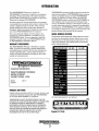
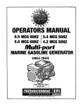
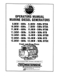
OPERATORS MANUAL
B.OKW ·60Hz SBEG /6.4KW • 50 Hz SBEG
1O.OKW • 60Hz SBEG I B.OKW • 50 Hz SBEG
12.5KW • 60Hz SBEG /1 O.OKW • 50 Hz SBEG
14.0KW • 60Hz SBEG /11.6KW • 50 Hz SBEG
MARINE G
E GENERATORS
OCTOBER 2012
CALIFORNIA PROPOSITION 65
WARNING
Exhaust gas from diesel and
gasoline engines (and some of
its constituents) are known to
the State of California to cause
cancer, birth defects, and other
reproductive harm.
A WARNING:
Exhaust gasses contain Carbon Monoxide, an odorless and
colorless gas. Carbon Monoxide is poisonous and can cause
unconsciousness and death. Symptoms of Carbon Monoxide
exposure can include:
•Dizziness
• Throbbing in Temples
•Nausea.
• Muscular Twitching
•Headache
• Vomiting
• Weakness and Sleepiness •Inability to Think Coherently
IF YOU OR ANYONE ELSE EXPERIENCE ANY OF THESE SYMPTOMS,
GET OUT INTO THE FRESH AIR IMMEDIATELY. If symptoms persist,
seek medical attention. Shut down the unit and do not restart
until it has been inspected and repaired.
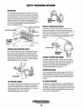
A WARNING DECAL is provided by WESTERBEKE and
should be fixed to a bulkhead near your engine or
generator.
WESTERBEKE also recommends installing CARBON
MONOXIDE DETECTORS in the living/sleeping quarters
of your vessel. They are inexpensive and easily
obtainable at your local marine store.
WARNING
G-=-~~
~
/-.y/WESTERBEKE
)GENERATORS
SAFE
co
I lAIII
WESTERBEKE CORPORA T/ON • MYLES STANDISH INDUSTRIAL PARK
!50 JOHN HANCOCK ROAD, TAUNTON, MA 02780-7319 U.S.A.
TEL: (508) 823-7677 • FAX: (508) 884-9688· • Website: www. westerbeke.com
Gasoline with an ETHANOL content
higher than 10% (E10) is not allowed
and may void warranty.
Engines & Generators
SAFETY INSTRUCTIONS
INTRODUCTION
PREVENT BURNS - FIRE
Read this safety manual carefuUy. Most accidents are
caused by failure to foUow fundamental rules and
precautions. Know when dangerous conditions exist and
take the necessary precautions to protect yourself, your
personne~ and your machinery.
The foUowing safety instructions are in compliance with
the American Boat and Yacht Council (ABYC) standards.
•
PREVENT ELECTRIC SHOCK
•
A WARNING: Oo not touch AC electrical connections
while engine is running, or when connected to shore
power. Lethal voltage is present at these connections!
•
•
•
•
•
•
•
Do not operate this machinery without electrical
enclosures and covers in place.
Shut off electrical power before accessing electrical
equipment.
Use insulated mats whenever working on electrical
equipment.
Make sure your clothing and skin are dry, not damp
(particularly shoes) when handling electrical equipment.
Remove wristwatch and all jewelry when working on
electrical equipment.
Do not connect utility shore power to vessels AC
circuits, except through a ship-to-shore double throw
transfer switch. Damage to vessels AC generator may
result if this procedure is not followed.
Electrical shock results from handling a charged capacitor. Discharge capacitor by shorting terminals together.
A WARNING: Fire can cause injury or death!
•
•
•
PREVENT BURNS - EXPLOSION
A WARNING: Explosions from fuel vapors can cause
injury or death!
•
•
PREVENT BURNS - HOT ENGINE
A WARNING: Oo not touch hot engine parts or
•
•
exhaust system components. A running engine gets
very hot!
•
Always check the engine coolant level at the coolant
recovery tank.
A WARNING: Steam can cause injury or death!
•
In case of an engine overheat, allow the engine to cool
before touching the engine or checking the coolant.
Prevent flash fires. Do not smoke or permit flames or
sparks to occur near the carburetor, fuel line, filter, fuel
pump, or other potential sources of spilled fuel or fuel
vapors. Use a suitable container to catch all fuel when
removing the fuel line, carburetor, or fuel filters.
Do not operate with a Coast Guard Approved flame
arrester removed. Backfire can cause severe injury or
death.
Do not operate with the air cleaner/silencer removed.
Backfire can cause severe injury or death.
Do not smoke or permit flames or sparks to occur near
the fuel system. Keep the compartment and the
engine/generator clean and free of debris to minimize the
chances of fire. Wipe up all spilled fuel and engine oil.
Be aware - diesel fuel will burn.
•
•
•
•
Follow re-fueling safety instructions. Keep the vessels
hatches closed when fueling. Open and ventilate cabin
after fueling. Check below for fumes/vapor before
running the blower. Run the blower for four minutes
before starting your engine.
All fuel vapors are highly explosive. Use extreme care
when handling and storing fuels. Store fuel in a wellventilated area away from spark-producing equipment
and out of the reach of children.
Do not fill the fuel tank(s) while the engine is running.
Shut off the fuel service valve at the engine when servicing
the fuel system. Take care in catching any fuel that might
spill. DO NOT allow any smoking, open flames, or other
sources of fire near the fuel system or engine when servicing. Ensure proper ventilation exists when servicing the
fuel system.
Do not alter or modify the fuel system.
Be sure all fuel supplies have a positive shutoff valve.
Be certain fuel line fittings are adequately tightened and
free of leaks.
Make sure a fire extinguisher is installed nearby and is
properly maintained. Be familiar with its proper use.
Extinguishers rated ABC by the NFPA are appropriate
for all applications encountered in this environment.
SAFETY INSTRUCTIONS
ACCIDENTAL STARTING
TOXIC EXHAUST GASES
A WARNING: Accidental starting can cause injury
A WARNING: Carbon monoxide (CO) is a deadly gas!
or death!
•
•
Disconnect the battery cables before servicing the engine/
generator. Remove the negative lead first and reconnect
it last.
• Make certain all personnel are clear of the engine before
starting.
• Make certain all covers, guards, and hatches are
re-installed before starting the engine.
•
•
BAnERY EXPLOSION
A WARNING: Battery explosion can cause injury
•
or death!
•
Do not smoke or allow an open flame near the battery
being serviced. Lead acid batteries emit hydrogen, a
highly explosive gas, which can be ignited by electrical
arcing or by lit tobacco products. Shut off all electrical
equipment in the vicinity to prevent electrical arcing
during servicing.
• Never connect the negative(-) battery cable to the
positive (+) connection terminal of the starter solenoid.
Do not test the battery condition by shorting the terminals
together. Sparks could ignite battery gases or fuel vapors.
Ventilate any compartment containing batteries to prevent
accumulation of explosive gases. To avoid sparks, do not
disturb the battery charger connections while the battery
is being charged.
• Avoid contacting the terminals with tools, etc., to prevent
burns or sparks that could cause an explosion. Remove
wristwatch, rings, and any other jewelry before handling
the battery.
• Always turn the battery charger off before disconnecting
the battery connections. Remove the negative lead first
and reconnect it last when disconnecting the battery.
A WARNING: Carbon monoxide (CO) is an invisible
odorless gas. Inhalation produces flu-like symptoms,
nausea or death!
•
Do not use copper tubing in diesel exhaust systems. Diesel
fumes can rapidly destroy copper tubing in exhaust
systems. Exhaust sulfur causes rapid deterioration of
copper tubing resulting in exhaust/water leakage.
• Do not install exhaust outlet where exhaust can be drawn
through portholes, vents, or air conditioners. If the engine
exhaust discharge outlet is near the waterline, water could
enter the exhaust discharge outlet and close or restrict the
flow of exhaust. Avoid overloading the craft.
• Although diesel engine exhaust gases are not as toxic as
exhaust fumes from gasoline engines, carbon monoxide
gas is present in diesel exhaust fumes. Some of the
symptoms or signs of carbon monoxide inhalation or
poisoning are:
Vomiting
Inability to think coherently
Dizziness
Throbbing in temples
Muscular twitching
Headache
Weakness and sleepiness
Nausea
BATTERY ACID
A WARNING: Sulfuric acid in batteries can cause
AVOID MOVING PARTS
severe injury or death!
•
Ensure that the exhaust system is adequate to expel gases
discharged from the engine. Check the exhaust system
regularly for leaks and make sure the exhaust
manifolds/water-injected elbow is securely attached.
Be sure the unit and its surroundings are well ventilated.
Run blowers when running the generator set or engine.
Do not run the generator set or engine unless the boat is
equipped with a functioning marine carbon monoxide
detector that complies with ABYCA-24. Consult your
boat builder or dealer for installation of approved
detectors.
For additional information refer to ABYC T-22
(educational information on Carbon Monoxide).
A WARNING: Rotating parts can cause injury
When servicing the battery or checking the electrolyte
level, wear rubber gloves, a rubber apron, and eye
protection. Batteries contain sulfuric acid which is
destructive. If it comes in contact with your skin, wash it
off at once with water. Acid may splash on the skin or
into the eyes inadvertently when removing electrolyte
caps.
or death!
•
Do not service the engine while it is running. If a
situation arises in which it is absolutely necessary to
make operating adjustments, use extreme care to avoid
touching moving paits and hot exhaust system
components.
Engines & Generators
ii
SAFETY INSTRUCTIONS
ABYC, NFPA AND USCG PUBLICATIONS FOR
INSTALLING DIESEL ENGINES
•
Do not wear loose clothing or jewelry when servicing
equipment; tie back long hair and avoid wearing loose
jackets, shirts, sleeves, rings, necklaces or bracelets that
could be caught in moving parts.
• Make sure all attaching hardware is properly tightened.
Keep protective shields and guards in their respective
places at all times.
• Do not check fluid levels or the drive belts tension while
the engine is operating.
• Stay clear of the drive shaft and the transmission coupling
when the engine is running; hair and clothing can easily
be caught in these rotating parts.
Read the following ABYC, NFPA and USCG publications
for safety codes and standards. Follow their
recommendations when installing your engine.
ABYC (American Boat and Yacht Council)
"Safety Standards for Small Craft"
Order from:
ABYC
3069 Solomon's Island Rd.
Edgewater, MD 21037
NFPA (National Fire Protection Association)
"Fire Protection Standard for Motor Craft"
Order from:
NFPA
11 Tracy Drive
Avon Industrial Park
Avon, MA 02322
USCG (United States Coast Guard)
"USCG 33CFR183"
Order from:
U.S. Government Printing Office
Washington, D.C. 20404
HAZARDOUS NOISE
A WARNING: High noise levels can cause hearing
loss!
•
•
•
Never operate an engine without its muffler installed.
Do not run an engine with the air intake (silencer)
removed.
Do not run engines for long periods with their enclosures
open.
A WARNING: Do not work on machinery when you are
mentally or physically incapacitated by fatigue!
OPERATORS MANUAL
Many of the preceding safety tips and warnings are repeated
in your Operators Manual along with other cautions and
notes to highlight critical information. Read your manual
carefully, maintain your equipment, and follow all safety
procedures.
GASOLINE ENGINE AND GENERATOR INSTALLATIONS
Preparations to install an engine should begin with a
thorough examination of the American Boat and Yacht
Council's (ABYC) standards. These standards are a
combination of sources including the USCG and the NFPA.
Sections of the ABYC standards of particular interest are:
H-2 Ventilation
P-1 Exhaust Systems
P-4 Inboard Engines
E-9 DC Electrical Systems
All installations must comply with the Federal Code of
Regulations (FCR).
Engines & Generators
iii
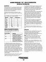
INSTALLATION
When installing WESTERBEKE engines and generators it is important that strict
attention be paid to the following information:
CODES AND REGULATIONS
Strict federal regulations, ABYC guidelines, and safety codes must be complied with
when installing engines and generators in a marine environment.
SIPHON-BREAK
For installations where the exhaust manifold/water injected.eXhaust elbow is close to
or will be below the vessel's waterline, provisions mu~t be made to install a siphonbreak in the raw water supply hose to the exhaust elbow. This hose must be looped a
minimum of 20" above the vessel's waterline. Failure to use a siphon-break when
the exhaust manifold/water injected exhaust elbow is near or below the loaded
water line of the vessel will result in raw water damage to the engine and possible
flooding of the vessel.
If you have any doubt about the position of the water-injected exhaust elbow relative
to the vessel's waterline under the vessel's various operating conditions, install a
siphon-break.
NOTE: A siphon-break requires periodic inspection and cleaning to ensure proper
operation. Failure to properly maintain a siphon-break can result in catastrophic
engine damage. Consult the siphon-break manufacturer for proper maintenance.
EXHAUST SYSTEM
The exhaust system's hose MUST be certified for marine use. Conugated Mmine
Exhaust Hose is recommended. The use of this type of hose allows for extreme bends
and turns without the need of additiinal fitting and clamps to accomplish these bends
and turns .In this regard, a single length of conugated exhaust hose can be used. The
system MUST be designed to prevent the entry of water into the exhaust system
under any sea conditions and at any angle of vessels heal.
A detailed Marine Installation Manual covering gasoline and diesel
engines and generators is supplied with every unit sold. This manual
.is also available in pdf format on our website to download
Website: www.westerbeke.com
Engines & Generators
iv
AVAILABLE FROM
YOUR WESTERBEKE
DEALER
SIPHON-BREAK WITH STAINLESS
LOOP FOR 1" HOSE
PART NO. 044010
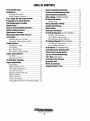
TABLE OF CONTENTS
Parts Identification .............................................2
Introduction .........................................................3
Engine Troubleshooting Guide .......................... 27
Electrical Troubleshooting Guide ..................... 29
System Monitoring Software ............................. 30
Data Logging (Troubleshooting) ........................ 31
DC Electrical System ........................................ .35
Warranty Procedure ...................................... .3
Serial Number Location ............................... .4
Fuel, Engine Oil and Engine Coolant .................. 5
Preparations for Initial Start-Up ......................... 6
Starting/Stopping Procedure ...............................7
Remote Panel ......................................................8
Break-In Procedure/Daily Operation ................... 8
Safety Shutdown Sensors ....................................9
Maintenance Schedule ..................................... 10
Measuring Exhaust Back Pressure .................... 11
Fuel System ....................................................... 12
Battery Care ................................................. 36
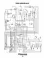
Wiring Schematic #49167 ................................ .37
Remote Panel Wiring ........................................ .38
Starter Motor .....................................................39
Generator Information ...................................... .41
AC Voltage Regulator (Current Models) ........... .42
Exciting the Generator ................................ .42
AC Voltage Connections ............................ .43
BE Generators/Early Models ....................... 44
AC Voltage Regulator (Early Models) ............... .46
AC Voltage Connections ............................ .47
Exciting the Generator ................................ .47
BE Generator (Troubleshooting) ....................... .48
Engine/Generator Specifications ..................... .49
Bleeding the Fuel System ............................ 13
Electronic Fuel Injection (EFI) ................... 14
Cooling System .................................................. l5
Changing Coolant ........................................ l5
Thermostat ................................................... 16
Raw Water Pump ......................................... 17
Raw Water Intake Strainer........................... 17
Engine Lubrication Oil.. ..................................... 18
Oil Filter ...................................................... 18
Remote Oil Filter. ........................................ 19
Shore Power Transfer Switch ............................50
Lay-Up and Recommissioning ...........................51
"CO" Data (Important) ......................................53
Installing a New Catalyst.. ................................54
Emissions Data .....................................:............ 55
Metric Conversions ...........................................56
Suggested Spare Parts ......................................57
Throttle Body Assembly ....................................20
Engine Adjustments ...........................................21
Spark Plugs .................................................. 21
High Tension Cords .................................... .21
Drive Belt Adjustment.. .............................. .21
Fuel Pressure Test.. ...................................... 21
Engine Compression Test ............................ 22
Ignition timing ............................................ .22
Valve Clearance .......................................... .23
Testing the Igniter. ...................................... .23
Timing Belt Inspection and Replacement ... 24
Engines & Generators
1
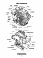
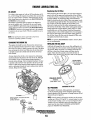
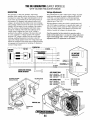
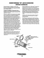
PARTS IDENTIFICATION .
CIRCUIT
BREAKER
SENSOR 1
FRONT
HEAT EXCHANGER.
SPIN-ON OIL FILTER
RIGHT SIDE
DC
20A CIRCUIT BREAKER RESET
MOUNT
LEFT SIDE
Engines & Generators
2
INTRODUCTION
This WESTERBEKE Generator is a product of
WESTERBEKE'S long years of experience and advanced
technology. We take great pride in the superior durability
and dependable performance of our engines and generators.
Thank you for selecting WESTERBEKE.
WESTERBEKE customers should also keep in mind the time
span between printings of WESTERBEKE product software
and the unavoidable existence of earlier WESTERBEKE
manuals. In summation, product software provided with
WESTERBEKE products, whether from WESTERBEKE or
other suppliers, must not and cannot be relied upon exclusively as the definitive authority on the respective product. It
not only makes good sense but is imperative that appropriate
representatives of WESTERBEKE or the supplier in question
be consulted to detennine the accuracy and currentness of the
product software being consulted by the customer.
In order to get the full use and benefit from your generator,
it is important that you operate and maintain it correctly. This
manual is designed to help you do this. Please read this
manual carefully and observe all the safety precautions
throughout. Should your generator require servicing, contact
your nearest WESTERBEKE dealer for assistance.
This is your Operators Manual. A Parts Catalog is also
provided and a Technical Manual is available from your
WESTERBEKE dealer. If you are planning to install this
equipment yourself, contact your WESTERBEKE dealer
for WESTERBEKE' S Installation Manual.
SERIAL NUMBER LOCATION
WARRANTY PROCEDURES
an~.or•o•r•d•en···ng. re•p•ru•.r•p•ar•ts
.
..........~. . . .~. . .~
.
The generator serial number and model number are located
on a decal on the generator housing. Take the time to enter
the information on the blank decal provided. This will provide a quick reference when seeking technical infonnation
Your WESTERBEKE Warranty is included in a separate
folder. If you have not received a customer identification
card registering your warranty 60 days after submitting the
warranty registration form, , please contatt the factory in
writing with model infom1ation, including the unit's serial
number and commission date
SPECIFICATI N
MODEL _______ _
••
••
RPM.·---------
KW -----------KVA -----------
1-.v-IWESTERBEKE
I Engines & Generators
VOLTS--------AMPS --------ENG. HP ------ENG. SER. NO.
Customer Identification
WESTERBEKE OWNER
MAIN STREET
HOMETOWN, USA
Model
GEN. SEA. NO.
PF/PHASE ---WIRES ________ _
Ser. #
RATING _______ _
Expires
INSUL CLASS __
TEMP. RISE ---BATIERY -----C.I.D. ----------
PRODUCT SOFTWARE
Product software (tech data, parts lists, manuals, brochures and
catalogs) provided from sources other than WESTERBEKE
are not within WESTERBEKE' S CONTROL.
Fill in the infomwtion for your reference.
~~~~~~~~~
WESTERBEKE CANNOT BE RESPONSIBLE FOR THE
CONTENT OF SUCH SOFTWARE, MAKES NO WARRANTIES
OR REPRESENTATIONS WITH RESPECT THERETO,
INCLUDING ACCURACY, TIMELINESS OR COMPLETENESS THEREOF AND WILL IN NO EVENT BE LIABLE
FOR ANY TYPE OF DAMAGE OR INJURY INCURRED IN
CONNECTION WITH OR ARISING OUT OF THE
FURNISHING OR USE OF SUCH SOFTWARE.
E~f!i=t:t =i=t~l
Engine I.D. Plate
Engines & Generators
3
INTRODUCTION
ORDERING PARTS
PROTECTING YOUR INVESTMENT
Whenever replacement parts are needed, always provide the
generator and engine model and serial numbers. In addition,
include a complete pmt description and part number for each
part needed (see the separately furnished Parts Catalog). Also
insist upon WESTERBEKE packaged parts because will fit
or generic parts are frequently not made to the same specifications as original equipment.
Care at the factory during assembly and thorough testing
have resulted in a WESTERBEKE generator capable of
many thousm1ds of hours of dependable service. However tl1e
manufacturer cannot control how or where the generator is
installed in the vessel or the manner in which the unit is
operated and serviced in tl1e field. This is up to the
buyer/owner-operator.
NOTE: Six important steps to ensure long generator life:
NOTES, CAUTIONS AND WARNINGS
• Proper engine and generator installation and alignment.
As this manual takes you through the operating procedures,
maintenance schedules, and troubleshooting of your generator, critical information will be highlighted by NOTES,
CAUTIONS, and WARNINGS. An explanation follows:
• An effiCient well-designed exhaust system that includes
an anti-siphon break to prevent water from entering the
engine.
NOTE: An operating procedure essential to note.
A
• Changing the engine oil and oil filters every I 00 operating hours.
• Proper maintenance of all engine and generator components according to the maintenance schedule in this
manual.
CAUTION: Procedures, which if not strictly
observed, can result in the damage or destruction of
the engine or generator.
• Use clean,ftltered unleaded fuel.
• Winterize your engine according to the "Lay-up and
Recommissioning" section in this manual.
A
WARNING: Procedures, which if not properly
followed, can result in personal injury or loss of life.
UNDERSTANDING THE GASOLINE GENERATOR
The gasoline engine driving an AC generator is in many
ways similar to a gasoline automobile engine. The cylinders
are verticle in-line, and the engine's cylinder head has an
overhead caiTishaft which is chain-driven. The engine utilizes
a solid-state distributor which is horizontally mounted and
caiTishaft-driven. The engine incorporates a pressure type
lubrication system, and a fresh water-cooled engine block
which is thermostatically-controlled. To a large degree, the
generator's engine requires the Saine preventive maintenance
that is required of a gasoline automobile engine. The most
important factors to the generator's longevity are proper
ventilation, maintenance of the fuel system, ignition system,
cooling system and the generator backend.
NOTE: A carbon monoxide warning decal has been provided
by WESTERBEKE. Affix this decal in a visable location in
the engine room.
SPARES AND ACCESSORIES
Certain spm·e parts will be needed to support and maintain
your WESTERBEKE generator or engine when cruising (see
SUGGESTED SPARE PARTS). Often even simple items such
as proper fuel and oil filter can be difficult to obtain along
the way. WESTERBEKE will provide you with a suggested
spares and accessories brochure to assist you in preparing an
on-board inventory of the proper WESTERBEKE pmts.
4
FUEL, ENGINE OIL AND ENGINE COOLANT
ENGINE COOLANT
GASOLINE
WESTERBEKE recommends a mixture of 50% antifreeze and
50% distilled water. Distilled water is free from the chemicals
that can corrode internal engine surfaces.
A CAUTION: Use unleaded 89 Octane gasoline or
higher. Ethanol gasoline must not exceed must not
exceed E10 (100/o). Gasoline with higher percentages of
Ethanol are not acceptable for use in these models and
can void the warranty.
The antifreeze performs double duty. It allows the engine
to run at proper temperatures by transferring heat away from
the engine to the coolant. It also lubricates and protects the
cooling circuit from rust and corrosion. Use a good quality
antifreeze that contains supplemental cooling additives (SCAs)
that keep the antifreeze chemically balanced, crucial to long
term protection.
The water and antifreeze should be premixed before being
poured into the cooling circuit.
When fueling, follow U.S. Coast Guard procedures, closing
hatches and companionways to prevent fumes from entering
the boat and cabins. Be sure to ventilate after fueling.
Care Of The Fuel Supply
NOTE: Use the new environmentally-friendly, long lasting,
antifreeze that is now available.
Use only clean fuel! The clearance of the components in
your fuel injection pump is very critical; invisible dirt
particles which might pass through the filter can damage
these finely finished parts. It is important to buy clean fuel,
and keep it clean. The best fuel can be rendered
unsatisfactory by careless handling or improper storage
facilities. To assure that the fuel going into the tank for your
engine's daily use is clean and pure, the following practice is
advisable:
Purchase a well-known brand of fuel.
A proper 50/50 mixture as recommended will protect the
engine coolant to temperatures of -400F
COOLANT RECOVERY TANK
A coolant recovery tank kit is supplied with each generator.
The purpose of this recovery tank is to allow for engine
coolant expansion and contraction during engine operation,
without the loss of coolant and without introducing air into
the cooling system.
Install and regularly service a good, Coast Guard approved
metal bowl type filter/water separator between the fuel tank
and the engine.
NOTE: It is recommended that the fuel system be bled during
each oil and filter change interval to ensure no air has
accumulated in the fuel system.
ENGINE OIL
Use a heavy duty engine oil with an API classification of SJ,
SL, or SM. Change the engine oil and filter after an initial 50
hours of engine break-in operation. Then follow the oil and
filter change intervals as specified in the MAINTENANCE
SCHEDULE in this manual.
Westerbeke Corporation does not approve or disapprove
the use of synthetic oils. If synthetic oils are used, engine
break-in MUST be performed using conventional oil. Oil
change intervals must be as listed in the MAINTENANCE
SCHEDULE section in this manual and not to be extended
if synthetic oils are used.
NOTE: The information above supersedes all previous
statements regarding synthetic oil usage.
Engines & Generators
5
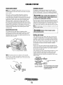
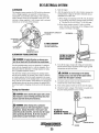
PREPARATIONS FOR INITIAL START-UP
PRESTART INSPECTION
• Visually examine the unit. Look for loose or missing
parts, disconnected wires, unattached hoses, and check
threaded connections. Search for any gasoline leaks.
Before starting your generator for the first time or after a prolonged layoff, check the following items:
a
Check load leads for con·ect connections as specified in
the wiring diagrams.
a
Check the engine oil level: add oil to maintain the level at
the full mark on the dipstick.
a
Check the fuel supply and examine the fuel filter/separator
bowls for contaminants.
a
Check the DC electrical system. Inspect wire connections
and battery cable connections.
Be sure no other generator or utility power is connected to
the load lines.
a
Be sure that in power systems with a neutral line that the
neutral is properly grounded (or ungrounded) as the system
requires, and that generator neutral is properly connected
to the load neutral. In single phase systems an incomplete
or open neutral can supply the wrong line-to-neutral
voltage on unbalanced loads.
a
Make certain the raw water thru-hull is open.
a
a
• Examine the air inlet and outlet for air flow obstructions.
Check the coolant level in both the plastic recovery tank
and at the manifold.
NOTE: After the initial rwming of the generator, the air in
tho! engine's cooling system will be purged to the coolant
recovery tank. Open the air bleed petcock to ensure that
the cooling system is purged of air. After shutdown and
after the engine has cooled, the coolant from the recovery
tank will be drawn into the engine's cooling system to
replace the purged air.
A
CAUTION: Wheil starting the generator, it is
recommended that all AC loads, especially large
motors, be switched OFF until the engine has come
up to speed and, in cold climates, starts to warm up.
This precaution will prevent damage caused by
unanticipated operation of the AC machinery and will
prevent a cold engine from stalling.
Before subsequent operation of the generatm; the engine's
manifold should be topped off, and the coolant recovery
tank may need to be filled to the MAX level.
OIL FILL
AIR BLEED
PETCOCK
6
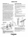
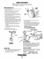
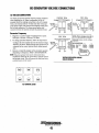
STARTING/STOPPING PROCED
GENERATOR CONTROL PANEL
AC CIRCUIT
BREAKER ---~1
CONNECTIONS
FIREBOY, CO DETECTOR
AND/OR AUXILIARY STOP
CONNECTION
Starting
REMOTE START/STOP PANEL
Simply press the START switch and the generator will start.
.A green light will glow indicating the generator is running.
The components on the panel are:
1. A three position start/stop rocker switch.
2. A green LED run indicator light on the rocker switch.
3. A four position LED fault shut down display board.
The start/stop rocker switch functions the same as the
start/stop rocker switch on the generator's control panel as
previously explained.
The start/stop rocker switch indicator light on the. rocker
switch will illuminate when the start circuit is energized. It
will go dim as the engine cranks and will brighten as the
engine starts to indicate the generator is running.
The LED fault shut down display board has four separate LED
lights to display to the operator the cause of the generators
automatic shut down. The four LED displays are: low oil
pressure, high engine operating temperature, high exhaust
temperature and engine over-speed/under-speed (flashes).
Should the generator shut down from one of these faults, the
fault LED will remain illuminated. To reset the LED, the stop
switch must be momentarily depressed.
This remote panel is a plug-in accessory and is available with a
15' to 100' wiring harness.
Stopping
To stop-depress the STOP side of the start switch, the green
light will go out and the generator is stopped.
Failure to Start
The start cycle will automatically terminate if the unit fails to
start after 12-14 seconds of cranking. Wait 20 seconds, then
repeat the start.
If the unit again fails to start, investigate the cause.
Sometimes after servicing the fuel system or changing the
fuel filter, air can accumulate in the fuel line or the throttle
body and prevent starting.
The Schrader valves on the throttle body and the fuel cell are
used to remove trapped air. This air is mixed with fuel and
under high pressure. Follow the BLEEDING THE FUEL
SYSTEM instructions in this manual. ·
O
rw=jWESTERBEKE
lou~
1
START
I
j
EJ\IGINE TEMP
•
O
CAUTION: Repeated crank cycles without a start can result
in the engine's exhaust system filling with raw water. This
raw water can enter the engine's cylinders by way of the
exhaust manifold once the system fills. If after three crank
cycles the unit does not start. Drain the system's muffler
and investigate and correct the cause of no start. Engine
damage the result of raw water entry is not a warrantable
issue. The operator should keep this in mind.
1o~~~
£XH TEMP
STOP
D
0
REMOTE CONTROL PANEL
7
STARTING/STOPPING PROC
GENERATOR CONTROL PANEL
AC CIRCUIT
BREAKER - - - + J i .
FIREBOY, CO DETECTOR
AND/OR AUXILIARY STOP
CONNECTION
Starting
REMOTE START/STOP PANEL
Simply press the START switch and the generator will start.
A green light will glow indicating the generator is running.
The components on the panel are:
1. A three position start/stop rocker switch.
2. A green LED run indicator light on the rocker switch.
3. A four position LED fault shut down display board.
The start/stop rocker switch functions the same as the
start/stop rocker switch on the generator's control panel as
previously explained.
The start/stop rocker switch indicator light on the. rocker
switch will illuminate when the start circuit is energized. It
will go dim as the engine cranks and will brighten as the
engine starts to indicate the generator is running.
The LED fault shut down display board has four separate LED
lights to display to the operator the cause of the generators
automatic shut down. The four LED displays are: low oil
pressure, high engine operating temperature, high exhaust
temperature and engine over-speed/under-speed (flashes).
Should the generator shut down from one of these faults, the
fault LED will remain illuminated. To reset the LED, the stop
switch must be momentarily depressed.
This remote panel is a plug-in accessory and is available with a
15' to 100' wiring harness.
Stopping
To stop-depress the STOP side of the start switch, the green
light will go out and the generator is stopped.
Failure to Start
The start cycle will automatically terminate if the unit fails to
start after 12-14 seconds of cranking. Wait 20 seconds, then
repeat the start.
If the unit again fails to start, investigate the cause.
Sometimes after servicing the fuel system or changing the
fuel filter, air can accumulate in the fuel line or the throttle
body and prevent starting.
The Schrader valves on the throttle body and the fuel cell are
used to remove trapped air. This air is mixed with fuel and
under high pressure. Follow the BLEEDING THE FUEL
SYSTEM instructions in this manual.
fW{WESTERBEKE
0
.l~cP~J
1
I I
ENGII\E TEMP
•
START
OT
CAUTION: Repeated crank cycles without a start can result
in the engine's exhaust system filling with raw water. This
raw water can enter the engine's cylinders by way of the
exhaust manifold once the system fills. If after three crank
cycles the unit does not start. Drain the system's muffler
and investigate and correct the cause of no start. Engine
damage the result of raw water entry is not a warrantable
issue. The operator should keep this in mind.
1o~~l
EXH TEMP
3.94
STOP
D
0
REMOTE CONlROL PANEL
7
BREAK-IN PROCEDURE/THE DAILY OPERATION
BREAK-IN PROCEDURE
NOTE: Some unstable running may occur in a cold engine.
This condition should lessen as normal operating temperature
is reached and loads are applied.
After the generator has been started, check for proper
operation and then encourage a fast warm-up. Run the
generator between 20% and 60% of full-load for the first
10 hours.
A CAUTION: Do not operate the generator for long
periods of time without a load being placed on the
generator.
A CAUTION: Do not attempt to break-in your
generator by running without a load.
STOPPING THE GENERATOR
After the first 10 hours of the generators operation, the load
can be increased to the full-load rated output, then
periodically vary the load.
Avoid overload at all times. An overload is signaled by
smoky exhaust with reduced output voltage and frequency.
Monitor the current being drawn from the generator and keep
it within the generators rating. Since the generator operates at
1800 rpm to produce 60 hertz, control of the generator's
engine break-in is governed by the current drawn from the
generator.
To protect against unintentional overloading of the generator,
the generator's output leads should be routed through a
circuit breaker that is rated at the rated output of the
generator.
Remove the major AC liads from the generator one at a time.
Allow the generator to run for a few minutes to stabilize the
operating temperature and press the STOP switch down.
(See CONTROL PANELS).
NOTE: After the first 50 hours of generator operation, check
the maintenance schedule for the 50 hour service check.
GENERATOR ADJUSTMENTS
Once the generator has been placed in operation and ad
break-in is/has taken place, a no-load voltage adjustment
maybe needed along with a GAIN adjustment. See VOLTAGE
ADJUSTMENT and ECU ADJUSTMENTS in this manual.
NOTE: Be aware of motor starting loads and the high current
drawn required for starting motors. The starting amperage
drawn can be 3 to 5 times normal running amperage. See
GENERATOR INFORMATION in this manual.
A CAUTION: VENTILATION
Gasoline vapors can explode. Before starting the engine,
operate the blower for at least four minutes and check both
the engine compartment and bilge for gasoline vapors.
Run the blower below cruising speed.
CHECK LIST
Follow this check list each day before starting your generator.
• Record the hourmeter reading in your log (engine hours
relate to the maintenance schedule).
• Visually inspect the generator for fuel, oil, or water leaks.
• Check the oil level (dipstick).
• Check the coolant level in the coolant recovery tank.
• Check your fuel supply.
• Check the starting batteries (weekly).
• Check drive belts for wear and proper tension (weekly).
• Check for abnormal noise such as knocking, vibration and
blow-back sounds.
• Check drive belts for wear and proper tension (weekly).
• Confirm exhaust smoke:
When the engine is cold- white smoke.
When the engine is warm - almost smokeless.
When the engine is overloaded - some black smoke.
8
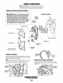
SAFETY SHUTDOWN SWITCHES
DESCRIPTION
The engine/generator is protected by switches and sensors
that send signals to the ECU that it interprets as a fault and
automatically shuts down the generator drive engine. When
an automatic shutdown occurs, one of the control panel fault
LED lights will illuminate indicating what fault caused the
engine to shutdown. This LED will stay illuminated. To
correct the fault, refer to ENGINE TROUBLESHOOTING in
this manual. Do not attempt to restart the generator
before correcting the fault.
~EXHAUST TEMPERATURE
·
~~
ENGINE
~ TEMPERATURE
~)
1
I
OIL PRESSURE
EXHAUST TEMPERATURE SWITCH
A temperature switch is mounted on the exhaust elbow to
monitor the temperature of the exhaust coolant and gasses.
Should the switch sense an excessive exhaust temperature, the
ECU will shut the generator down and the exhaust
temperature LED will illuminate on the control panel. Should
this occur, refer to ENGINE TROUBLESHOOTING in this
manual.
TO FUSE
CONTROL PANEL INDICATOR LIGHTS
Four LED fault lights are located on the generator control
panel and the remote start/stop panels. Should a problem
occur during generator operation the individual light will
indicate where the problem is and at the same time shut the
generator down. The light will continue to glow after the
generator shuts down. Should this occur, refer to f;NGINE
TROUBLESHOOTING in this manual.
THERMOSTAT
ASSEMBLY
COOLANT TEMPERATURE SENSOR
Acoolant temperature sensor is located on the thermostat
housing to monitor the engines fresh water coolant. Should
the coolant temperature reach 210°F, the ECU will shut the
generator down and the engine temperature LED will
illuminate. Should this occur, refer to ENGINE
TROUBLESHOOTING in this manual.
OVERSPEED SWITCH
An overspeed high RPM shutdown sensor in the ECU will
shut the engine down if the engine RPM''S exceed the set
limit and the LED will remain lit. If an underspeed problem
occurs, the engine will shutdown and the LED will remain
flashing.
OIL PRESSURE SENSOR
DC CIRCUIT BREAKER
An oil pressure sensor (located just below the oil filter) sends
a DC voltage to the ECU that it interprets as oil pressure.
Should this voltage fall below a certain level, the ECU will
shut the generator down and illuminate the low oil pressure
LED. Should this occur, refer to ENGINE
TROUBLESHOOTING in this manual.
The generators engine is protected by a panel mounted manual reset circuit breaker (20 amp). An electrical overload in
the engine's wiring harness or the instrument panel will trip
this breaker and shutdown the engine/generator. If this should
occur, inspect and repair the problem. then reset the breaker
and sestart the engine/generator.
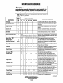
MAINTENANCE SCHEDULE
A WARNING: Never attempt to perform any service while the engine is
running. Wear the proper safety equipment such as goggles and gloves, and
use the correct tools for each job. Disconnect the battery terminals when
servicing any of the engine's DC electrical equipment.
ISAEElMaintenance items that are very important to the proper operation of
"Safe CO" generators.
~
SCHEDULED
MAINTENANCE
CHECK
EACH
DAY
HOURS OF OPERATION
50
100
250
500
MAINTENANCE DESCRIPTION
750 1000 1250
Unleaded gasoline with octane rating of 89 of higher
Fuel/Water Separator
D
D
Engine Oil Level
D
Oil level should indicate between MAX. and LOW on
dipstick.
Coolant Level
D
Check at recovery tank; if empty, check at manifold.
Add coolant if needed.
D
Inspect for proper tension (3/8" to 1/2' deflection)
and adjust if needed. Check belt edges for wear.
Fuel Supply
Drive Belts
Check for water and dirt in fuel (drain/replace filter if
necessary).
weekly
Visual Inspection of Engine
Sparks Plugs
D
·ISN>EI
Starting Batteries
(and House Batteries)
will inhibit the engine's ability to remain cool.
Check for fuel, oil and water leaks. Inspect wiring and
electrical connections. Keep bolts & nuts tight. Check
for loose belt tension.
D
Check gap, inspect for burning and corrosion.
NOTE: Keep engine surface clean. Dirt and oil
D
D
D
D
D
D
Every 50 operating hours check electrolyte levels
and make sure connections are very tight. Clean off
excessive corrosion.
weekly
Engine Oil
D
D
D
D
D
D
D
Initial engine oil and filter change at 50 hours, then
change both every 100 hours.
Generator
D
D
D
D
D
D
D
Check that AC connections are clean and secure with
no chafing-see GENERATOR INFORMATION.
Fuel Lift Pump
D
Periodically inspect for leaks, electrical connections
are clean and tight.
Air Screen I5N>EI
Exhaust System
D
D
Clean at 50 hrs., then every 100 hours.
Engine Hoses
D
D
D
D
D
D
D
D
D
D
D
D
D
D
D
D
Coolant System
Fuel Filter
Inlet Fuel Filter
D
D
Raw Water Pump
Heat Exchanger
D
D
D
D
D
Initial check at 50 hours, then every 250 hours.
Inspect for leaks. Check anti-siphon valve operation.
Check the exhaust elbow for carbon and/or corrosion
buildup on inside passages; clean and replace as
necessary. Check that all connections are tight.
D
Hose should be hard & tight. Replace if hoses
become spongy. Check and tighten all hose clamps.
Remove the pump cover and inspect for wear.
Inspect impeller, cam and wear plate. Replace gasket.
Lubricate impeller when reassembling.
D
D
D
Clean or replace anode. Open heat exchanger end
cap and clean out debris. Remove every 1000 hours
for professional cleaning and pressure testing.
Drain, flush, arid refill cooling system with
appropriate antifreeze mix.
D
D
Change every 250 operating hours.
Change every 250 operating hours.
D
D
D
D
D
(continued)
Engines & Generators
10
MAINTENANCE SCHEDULE
NOTE: Use the engine hourmeter gauge to log your engine hours or record your
engine hours by running time.
SCHEDULED
MAINTENANCE
CHECK
EACH
DAY
HOURS OF OPERATION
50
250
500
MAINTENANCE DESCRIPTION
750 1000 1250
D
*Starter Motor
Distributor
100
1m]
D
D
D
Check solenoid and motor for corrosion. Remove
and lubricate. Clean and lubricate the starter motor
pinion drive.
Check ignition timing. Check condition of distributor
cap and rotor.
*Engine Cylinder
Compression and
Valve Clearances
D
D
*Engine Timing Belt
D
Remove and replace every 1000 hours.
NOTE: Failure to replace the timing belt at the
recommended interval could result in timing chain
failure resulting in major damage to the engine.
*Exhaust Elbow
D
Test exhaust elbow for casting integrity. Replace if
casting is corroded or deteriorated.
NOTE: A defective exhaust elbow can cause
carbon monoxide leakage!
I
Catalytic Converter
@.]
*Exhaust System Back
Pressure
Catalyst
D
D
Incorrect valve clearance will result in poor engine
performance, check compression pressure and
timing and adjust valve clearances.
Remove water injected exhaust elbow and visually
inspect. Replace every 2000 hours.
Perform back pressure test to ensure system is not
developing restrictions that will increase pressure
above 1.5 PSI or 41 inches of water column at full
operating amperage load. Correct as needed.
.lmJ
Oxygen Sensor l5~~J
CO in Exhaust
D
Remove water injected exhaust elbow and visually
inspect every 2000 hours. Replace as needed.
D
D
Inspect every 1000 hours. Replace every 2000 hours.
Sample with CO analyzer.
*WESTERBEKE recommends this service be performed by an authorized mechanic.
MEASURING EXHAUST BACK PRESSURE
PSI
GAUGE
Exhaust systems normally produce resistance to the flow of
exhaust gases, causing back-pressure. Back-pressure must be
kept within a certain limit. Check the back-pressure before
the generator is put back into service.
To test exhaust pressure, connect either a water colunm or
PSI tube to the test part on the exhaust elbow as shown.
Check the exhaust back-pressure before the generator is put
into service. Measure the back-pressure after the engine has
reached its normal operating temperature, and at the point
where it is about to reach its rated load at either 1500 rpm
(for 50Hz applications) or 1800 rpm (for 60Hz applications).
Back-pressure should not exceed 1.5 psi (0.11 kg/em\
A water colunm can be made by taping one end of a clear
plastic tube along a yardstick and fitting the other end of the
tube with a 1/4" NPT pipe fitting.
Back-pressure should not exceed 27in (69cm) of water in the·
water colunm.
MEASURING EXHAUST BACK
PRESSURE
Engines & Generators
11
FUEL SYSTEM
GASOLINE·
ENGINE FUEL FILTER
Use unleaded 89 Octane gasoline or higher. Ethanol gasoline
must not exceed ElO (10%). Gasoline with higher percentages of Ethanol are not acceptable for use in these models
and can void ;the warrenty.
When fueling, follow US. Coast Guard procedures, closing
hatches and companionways to prevent fumes from entering
the boat and cabins. Be sure to ventilate after fueling.
Periodically check the fuel connections and the bowl for
leakage. Replace the filter element after the first 50 hours
then follow the MAINTENANCE SCHEDULE.
Changing Filter Element
1. Shut the fuel supply to the generator off.
2. Ensure there is no pressure in the fuel system by bleeding
off any existing pressure using a Schrader valve on the
throttle body and fuel cell. Use a pressure testing kit as
shown on the next page.
3. Unscrew the fuel bowl from the housing and allow the
bowl to come away from the housing.
4. Remove and replace the filter element and clean the
bowl.
5. Inspect both "0" rings. Replace if necessary.
6. Press on a new filter and replace the filter bowl.
7. Open the fuel supply. Inspect for leaks.
NOTE: The generator compartment should have a gasoline
fume detector/alarm properly installed and working.
GASOLINE/WATER SEPARATOR AND
A primary fuel filter of the water separating ~---·-,
type must be installed between the fuel
and the engine to remove water and other
contaminant's from the fuel before they can
be carried to the fuel system on the engine.
Most installers include a type of filter/water
separator with the installation package as
they are aware of the problems that
contaminant's in the fuel can cause.
These gasoline filters must have metal bowls
(not "see-through") to meet U.S. Coats Guard
requirements. The metal bowls bave drain
valves to use when checking for water and
impurities.
WESTERBEKE oAr:J•T.-.::=r
INLET FUEL FILTER
1. Shut off the fuel supply to the generator. Disconnect the
fuel supply line to the inlet filter and unscrew the filter
from the pump inlet. Take care to catch any fuel that may
be present.
2. Thread on the replacement inlet filter and connect the
fuel supply line. Use care when connecting and
tightening the fuel supply line so as not to distort the
inlet filter.
3. Tum on the fuel supply to the generator and start the
generator. Ensure that there are no leaks.
. NUMBER (49602)
I
I
I
f'FROMFUEL
j COOLER
FUEL PUMP
I
Periodically check the fuel connections to and out of the pump
and make sure that no leakage is present and that the fittings
are tight and secure. The engine mounted fuel pump is
maintenance free.
FUEL CELL
ENGINE FUEL FILTER
·..v- WESTERBEKE
NOTE: It is recommended that the fuel system be bled during
each oil and filter change interval to ensure no air has
accumulated in the fuel system.
Engines & Generators
12
FUEL SYSTEM
BLEEDING THE FUEL SYSTEM
1. Insure that the fuel cell is not connected to the wiring
harness, and that the lift pump is connected.
2. Attach Snap On MT337B, OTC 7211 or equivalent fuel
pressure gauge set to the Schrader valve on fuel cell.
A CAUTION: Follow manufacturer's instructions for
"SNAP-ON-TOOL" PROVIDES AN
EXCELLENT PRESSURE GAUGE KIT
FOR PRESSURE TESTING AND
BLEEDING SCHRADER TEST PORTS
safe use of the gauge sets to purge a high-pressure fuel
system.
3.
While holding the stop switch in the (prime) depressed
position, purge the air from the fuel cell. The fuel cell is
purged when no air bubbles are visible escaping from the
drain line attached to the Schrader valve. Pressure should
typically be 3-4 psi.
4. Remove the pressure gauge set from the fuel cell and
connect it to the Schrader valve on the throttle body.
8. Remove the pressure gauge set, and cap all Schrader
valves.
9. Insure that all wire connections are secure and that there
are no leaks in the fuel system.
A WARNING: Take care to catch any
fuel that may be spilled and properly
dispose of the fuel rags.
5. Connect the fuel cell to the wiring harness.
6. Open the valve on the fuel pressure gauge purge line. Do
not prime the system without the fuel gauge purge valve
open or air can be forced back into the fuel cell. If this
happens, repeat steps 1, 2, and 3 to remove the trapped
air from the fuel cell.
7. Repeat step 3, this time purging the air completely from
the throttle body. The pressure should be 40 psi in the
throttle body after purging the system.
FUEL COOLER
#052004
'NOTE: The system can develop 40 psi without being fully
p~~ged.. The system i~ fully purged when no bubbles are
vzszble m the purge lme.
TO THROTTLE 800
J
\
I
i
I
I
FUEL FILTER
1 --~
FUEL PUMP
#053339
\\l'..---1----t~..----
INLET FUEL FILTER
#048076
ELECTRONIC FUEL INJECTION
NOTE: When changing the generator frequency, tum OFF
the DC 20 amp breaker before moving the dipswich.
The vacant program connector is used by the factory to input
the operating program into the ECU. This connector can be
used with software to monitor the operation of the Safe CO
system. Contact your MD to obtain free software.
TO
The electrical connections from the engine electrical harness
are made to the ECU through two plug connections, one 23
pin and one 35 pin and may therefore vary in number
·according to the generator model. For further details, consult
the engine circuit wiring diagram in this manual.
The ECU is normally set for operation at 60Hz unless
specified otherwise, and is internally configured for a 4 pole
generator. If it is necessary to replace the ECU, make sure it
is configured by label for the generator in use.
ECU ADJUSTMENTS
Stability Trim (Gain)
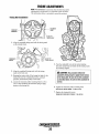
The above illustration shows the throttle body assembly that
attaches to the intake manifold.
An electronic control unit (ECU) controls the fuel injector
and the stepper motor.
The ECU is supplied with engine operating conditions from
sensors that monitor intake air temperature, engine coolant
temperature, map sensor (intake manifold absolute pressure),
engine rpm and battery voltage.
When changing engine speed, or if no engine hunting
condition should occur, the gain pot may require adjustment.
There is no specific set point for this adjustment and it is
normally set to the middle of its range or to a point in its
range which obtains optimal engine speed response without
any tendency of hunting.
Setting Engine Speed
The engine speed can be set for operation at either 50 or 60
Hz. Corresponding engine speeds for a 4 pole generator are
1500 rpm or 1800 rpm.
1. Set up whatever equipment is to be used to measure
engine speed or generator output frequency.
The ECU interprets this information to determine the
appropriate injector pulse rate and throttle opening position.
2. Start up and run the generator at the cmTent operating
A high pressure fuel pump supplies fuel to the area around
the injector and the regulator maintains the fuel pressure in
that area at 35 - 40 PSI maximum.
3. Adjust the GAIN setting between 40 - 60 for best system
reaction to AC amperage load changes.
The injector is a solenoid operated pintle valve that meters
fuel into the intake manifold depending on engine operating
conditions and generator amperage load determined by the
ECU.
Air flow into the intake manifold is controlled by the ECU
operation of the throttle plate via the stepper motor.. Throttle
plate positioning for proper air flow into the engine is
accomplished through the ECU interpretation of engine
operating conditions. The Schrader valve is used to'
monitor/check fuel pressure around the fuel injector.
·speed and frequency.
·
NOTE: A higher GAIN adjustment can induce unstable engine
operation. In such cases, lessen the GAIN adjustment.
Replacing the ECU
Remove the control box cover. Before attempting to remove
the ECU, tum OFF the 20 amp DC control panel breaker.
Unplug the two engine harness connections. Then unscrew
the four side screws securing the ECU and remove it from
it's holder. To install a new ECU, reverse the procedure.
ECU
ELECTRONIC CONTROL UNIT (ECU)
The ECU (Electronic Control Unit) is factory programmed
and requires no adjustments by the generator operator. It PROGRAM
controls all starting, operating and safety shutdown feattrres CO
on the engine. The Gain Pot is set at #50 midpoint for
optimum system resp<mse.
Dipswitch #1 is used to charge the generators frequency.
ON is for 50 hertz and OFF is for 60 hertz operation. The
remaining switches #2, 3#. and #4 service no functions.
ADJUSTMENT POT
14
COOLING SYSTEM
FRESH WATER CIRCUIT
CHANGING COOLANT
NOTE: Refer to ENGINE COOLANT section for the recommended antifreeze and water mixture to be used as the fresh
water coolant.
The engine's coolant must be changed according to the
MAINTENANCE SCHEDULE. If the coolant is allowed to
become contaminated, it can lead to overheating problems.
Fresh water coolant is pumped through the engine by a
circulating pump, absorbing heat from the engine. The
coolant then passes through the thermostat into the manifold,
to the heat exchanger where it is cooled and returned to the
engine block via the suction side of the circulating pump.
When the engine is started cold, external coolant flow is
prevented by the closed thermostat (although some coolant
flow is bypassed around the thermostat to prevent the exhaust
manifold from overheating). As the engine warms up, the
thermostat gradually opens, allowing full flow of the engine's
coolant to flow unrestricted to the external portion of the
cooling system.
A CAUTION: Proper cooling system maintenance is
critical; a substantial number of engine failures can be
traced back to cooling system corrosion.
Drain the engine coolant by removing the block drain plug
(right side of the block just above the oil pressure sensor) and
opening the manifold pressure cap. Flush the system with
fresh water, then reinstall the drain plug and refill the system.
NOTE: The drain plug on the heat exchanger can also be used
to drain engine coolant.
Coolant Recovery Tank
A WARNING: Beware of the hot engine coolant.
The coolant recovery tank allows for engine coolant
expansion and contraction during engine operation, without
the introduction of air into the cooling system. This tank
should be located at or above the engine manifold level and
should be easily accessible.
Wear protective gloves.
Refilling the Coolant
After replacing the engine block drain plug, close the heat
exchanger's coolant petcock. Slowly pour clean, premixed
antufreeze coolant into the water jacketed exhaust manifold
filler neck opening. Fill the system full, then start the engine.
Monitor the coolant in the manifold and add as needed. Fill
the manifold to the filler neck and install the manifold
pressure cap.
Remove the cap on the coolant recovery tank and fill with
coolant mix to halfway between LOW and MAX and replace
the cap. Run the engine and observe the coolant expansion
flow into the recovery tank.
After checking for leaks, stop the engine and allow it to cool.
Coolant should draw back into the cooling system as the
engine cools down. Add coolant to the recovery tank if
needed and check the coolant in the manifold. Clean up any
spilled coolant.
NOTE: Periodically check the condition of the manifold
pressure cap, its rubber seals and the vacuum return valve.
Ensure the passage from the filler neck to the recovery tank
connection is kept clear.
COOLANT EXPANSION
MANIFOLD
PRESSURE
CAP
15
KEEP THESE PASSAGES CLEAR TO ENSURE
A FULL FLOW OF COOLANT TO AND FROM
THE COOLANT RECOVERY TANK (A PIPE
CLEANER WORKS WELL)
COOLING SYSTEM
If the zinc anodes need replacement, hold the hex boss
into which the zinc anode is threaded with a wrench while
loosening the anode with another wrench. This prevents the
hex boss from possibly tearing off the exchanger shell. If the
zinc is in poor condition, there are probably a lot of zinc
flakes within the exchanger. Remove the end of the heat
exchanger and clean the inside of all zinc debris. Always
have a spare heat exchanger end gasket in case the present
one becomes damaged when removing the end cover.
Replace the gasket (refer to your engine model's heat
exchanger end gasket part number), 0-ring and cover, and
install a new zinc anode.
HEAT EXCHANGER
Cool raw water flows through the inner tubes of the heat
exchanger. As the engine coolant passes around these tubes
the heat of the internal engine is conducted to the raw water
which is then pumped into the exhaust system and discharged.
The engine coolant (now cooled) flows back through the engine
and the circuit repeats itsel£
The engine coolant and raw water are independent of each other,
this keeps the engine's water passages clean from the han11ful
deposits found in raw water.
Heat Exchanger Service
NOTE: The threads of the zinc anodes are pipe threads and
do not require sealant. Sealant should not be used as it
may insulate the zinc from the metal of the heat exchanger
housing preventing electrolysis action on the zinc.
After approximately 1000 hours of operation, remove, clean
and pressure test the engine's heat exchanger. (A local automotive radiator shop should be able to clean and test the heat
exchanger.)
NOTE: Operating in silty and/or tropical waters 111£lY require
that a heat exchanger cleaning be peifonned more often than
every 1000 hours.
·
THERMOSTAT
A thermostat, located near the manifold at the front of the
engine, controls the coolant temperature as the coolant
continuously flows through the closed cooling circuit. When
the engine is first started, the closed thermostat prevents
coolant from flowing (some coolant is by-passed through a
hole in the thermostat to prevent the exhaust manifold from
overheating). As the engine warms up, the thermostat
gradually opens. The thermostat is accessible and can be
checked, cleaned, or replaced easily. Carry a spar·e thennostat
and gasket.
Replacing the Thermostat
To avoid spilling coolant, drain the coolant down below the
manifold level (REFER TO CHANGING COOLANT).
Remove the cap screws and disassemble the the1mostat
housing as shown. When installing the new thermostat and
RAW WATER
gasket, apply a thin coat of sealant on both sides of the
CLEAR OUT
DRAIN
gasket before pressing it into place. Do not over-tighten the
ZINC DEBRIS
cap screws. Replace the coolant in the manifold. Run the
ZINC ANODE
engine and check for normal temperatures and that there are
A zinc anode, or pencil, is located in the raw water cooling ~ leaks at the thermostat housing.
circuit within the heat exchanger. The purpose of having
zinc anodes is to sacrifice them to electrolysis action taking
place in the raw water cooling circuit, thereby reducing the
effects of electrolysis on other components of the system.
The condition of the zinc anode should be checked monthly
and the anode cleaned or replaced as required. Spare anodes
should be canied on board.
NOTE: Electrolysis action is the result of each pm1icular
installation and vessel location; not that of the engine.
GASKET
APPLY SEALANT
AT ASSEMBLY
CLEAN & REUSE
THERMOSTAT
ASSEMBLY
NEW
ZINC ANODES
16
COOLING SYSTEM
RAW WATER PUMP(#42026)
RAW WATER INTAKE STRAINER
The raw water pump is a self-priming, rotary pump with a
non-ferrous housing and a neoprene impeller. The impeller has
flexible blades which wipe against a curved cam plate within
the impeller housing, producing the pumping action. On no
account should this pump be run dry as water acts as a
lubricant for the impeller. There should always be a spare
impeller and impeller cover gasket (an impeller kit) aboard.
Raw water pump impeller failures occur when lubricant (raw
water) is not present during engine operation. Such failures
are not warrantable, and operators are cautioned to make sure
raw water flow is present at start-up. The neoprene impeller
has a limited lifetime and must be inspected regularly.
NOTE: Always install the strainer at or below the waterline so
NOTE: Should a failure occur with the pump~ internal parts
(seals and bearings), it may be more cost effective to purchase
a new pump and rebuild the original pump as a spare.
the strainer will always be self-priming.
A clean raw water intake strainer is a vital component of the
engine's cooling system. Include a visual inspection of this
strainer when making your periodic engine check. The water
in the glass should be clear.
Perform the following maintenance after every 100 hours of
operation:
1. Close the raw water seacock.
2. Remove and clean the strainer filter.
3. Clean the glass.
4. Replace the sealing washer if necessary.
5. Reassemble and install the strainer.
6. Open the seacock.
Inspecting/Changing the Raw Water Pump Impeller
Close the raw water intake valve. Remove the pump cover
and, with the proper size impeller tool, carefully pry the
impeller out of the pump (the impeller can be pried out using
a pair of screwdrivers if an impeller puller is unavailable. Take
care not to tear the impeller). Install the new impeller and
0-ring. Move the blades to conform to the curved cam plate
and push the impeller into the pumps housing. When
assembling, apply a thin coating of lubricant to the impeller
and gasket. Open the raw water intake valve.
Run the engine and check for leaks around the pump. Also
check for water discharge at the stem tube. Absence of water
flow indicates the pump has not primed itself properly.
7. Run the engine and check for leaks.
NOTE: Also follow the above procedure after having run hard
aground.
If the engine temperature gauge ever shows a higher than
normal reading, the cause may be that silt, leaves or grass
may have been caught up in the strainer, slowing the flow of
raw water through the cooling system.
NOTE: Never allow the pump to run dry. Even a short period
of dry running may destroy the impeller.
INSPECT THE 0-RING
AND IMPELLER. REPLACE
IF THEY SHOW SIGNS
OF WEAR.
THE PIN FITS INTO THE-----IMPELLER
SLOT IN THE SHAFT.
~ ·
TYPICAL RAW WATER INTAKE STRAINER
(Owner Installed)
DRAINING THE RAW WATER COOLING SYSTEM
LIGHTLY GREASE THE
PUMP CHAMBER, 0-RING,
AND IMPELLER WITH
GLYCERIN.
When freezing temperatures are expected, the cooling system
can be drained by loosening the raw water pump's cover
plate screws. This should allow the water to drain out of the
pump and also drain back to the strainer.
A CAUTION: If any of the blades have broken off the
Open the raw water petcock/plug on the heat exchanger to
allow the raw water to drain.
impeller, they must be located to prevent blockage in
the cooling circuit. They often can be found in the heat
exchanger
Engines & Generators
17
ENGINE LUBRICATING OIL
Replacing the Oil Filter
OIL GRADE
Use a heavy duty engine oil with an API classification of SJ,
SL, or SM. Change the engine oil and filter after an initial 50
hours of engine break-in operation. Then follow the oil and
filter change intervals as specified in the MAINTENANCE
SCHEDULE in this manual.
Westerbeke Corporation does not approve or disapprove
the use of synthetic oils. If synthetic oils are used, engine
break-in MUST be performed using conventional oil. Oil
change intervals must be as listed in the MAINTENANCE
SCHEDULE section in this manual and not to be extended
if synthetic oils are used. SAE 15W-40 is suitable for use in
all seasons.
NOTE: The information above supersedes all previous
statements regarding synthetic oil usage.
CHANGING THE ENGINE OIL
The engine oil should be warm. Remove the oil drain hose
from its attachment bracket and lower it into a container and
allow the oil to drain, or attach a pump to the end of the drain
hose and pump the old oil out. Make sure the oil drain hose
is properly secured in its holder after all of the old oil has
been drained.
Always observe the old oil as it is removed. A yellow/gray
emulsion indicates the presence of water in the oil. Although
this condition is rare, it does require prompt attention to
prevent serious damage. Call a competent mechanic if water
is present in the oil. Raw water present in the oil can be the
result of a fault in the exhaust system attached to the engine
and/or a siphoning through the water cooling circuit into the
exhaust, filling into the engine.
When removing the used oil filter, you may find it helpful to
punch a hole in the upper and lower portion of the old filter
to drain the oil into a container before removing it. This helps
to lessen spillage. An automotive filter wrench should be
helpful in removing the old oil filter. Place some paper towels
and a plastic bag around the filter when unscrewing it to catch
any oil that's in the filter. Inspect the old oil filter as it is
removed to make sure that the rubber sealing gasket comes
off with the old oil filter. If this rubber sealing gasket remains
sealed against the oil filter adapter, gently remove it. When
installing the new oil filter element, wipe the filter gasket's
se~ling surface on the oil filter adapter free of oil and apply a
thm coat of clean engine oil to the rubber sealing gasket on
the oil filter. Screw the filter onto the threaded oil filter stub
and tighten the filter firmly by hand.
'
NOTE: Use genuine WESTERBEKE oil filters. Generic filters
are not recommended.
REFILLING THE OIL SUMP
Add fresh oil through the valve cover. After refilling the oil,
run the engine for a few moments while checking the engine's
oil pressure. Make sure there is no leakage around the new
oil filter or from the oil drain system, and then stop the
engine. Then check the quantity of oil with the lube oil
dipstick.
FillLto~,
\\not\~n FULL mark on the dipstick.
~ \'·">;/~
~ ""~
.:~...---
\~·</ ·;v
lfri!i(IU/";~~/~
SEALING
GASKET
.APPLY
CLEAN
OIL
WHEN ASSEMBLING
NEW FILTER
SPIN·ON OIL FILTER
#036918
TURN HAND TIGHT
OIL PRESSURE
CHANGING OIL FILTER
The engine's oil pressure, during operation, is indicated
by the oil pressure gauge on the instrument panel. During
normal operation, the oi:l pressure will range between 40 and
60 psi (2.8 and 4.2 kg/cm2).
NOTE: A newly started, cold engine can have an oil pressure
WARM THE ENGINE, SHUTDOWN AND DRAIN
THE OIL INTO A
SUITAl3LE CONTAINER
reading up to 60 psi (4.2 kg/cm2). A warmed engine can have
an oil pressure reading as low as 35 psi (2.5 kg/cm2). These
readings will vary depending upon the temperature of the
engine and the rpms. Refer to ENGINE ADJUSTMENT
pages for TESTING OIL PRESSURE.
1/4" NPT
FOR ADDING
AN EXTENSION
18
REMOTE OIL FILTER {OPTIONAL)
INSTALLATION
This popular accessory is used to relocate the engine's oil
filter from the engine to a more convenient location such as
an engine room bulkhead.
To install, simply remove the engine oil filter and thread on
WESTERBEKE's remote oil filter kit as shown. Always
install this kit with the oil filter facing down as illustrated.
Contact your WESTERBEKE dealer for more infonnation
NOTE: Refer to ENGINE OIL CHANGE in this manual for
instructions on removing the oil filta
NOTE: Westerbeke is not responsible for engine failure due to
incorrect installation of the Remote Oil Filta
A CAUTION: It is vital to install the oil lines cor·
rectly. If the oil flows in the reverse direction, the by·
pass valve in the filter assembly will prevent the oil
from reaching the engine causing an internal engine
failure. If there is no oil pressure reading, shutdown
immediately and check the hose connections.
APPLY A THIN COAT OF CLEAN OIL TO THE 0-RING WHEN
INSTALLING THIS KIT. THREAD THE KIT ON, THEN HAND
TIGHTEN AN ADDITIONAL 3/4 TURN AFTER THE 0-RING
CONTACTS THE BASE.
/
THE IN CONNECTION HOSE
MUST ATTACH TO THE OUT
CONNECTION AT THE
REMOTE OIL FILTER.
NOTE THE "IN" AND "OUT" MARKINGS
ON THE ADAPTER WHEN THE HOSES ARE
REMOVED FOR INSTALLATION SO THEY
WILL BE RECONNECTED CORRECTLY
THE OUT CONNECTION HOSE
MUST ATTACH TO THE IN
CONNECTION ATTHE
REMOTE OIL FILTER.
19
APPLY A THIN COAT OF CLEAN OIL TO THE FILTER
GASKET WHEN INSTALLING. AFTER THE FILTER
CONTAC1S THE BASE, TIGHTEN IT AN ADDITIONAL
3/4 TURN.
THROTTLE BODY ASSEMBLY
FUEL INJECTOR
SCHRADER
VALVE
FUEL
PRESSURE
REGULATOR
TO
PVC VALVE
STEPPER MOTOR
MAP SENSOR
FROM THE THERMOSTAT ASSEMBLY
c:-i"
DESCRIPTION
The above illustration shows the throttle body assembly
attached to the intake manifold.
An electronic control unit (ECU) controls the fuel injector
and the throttle actuator.
The ECU is supplied with engine operating conditions from
sensors that monitor intake air temperature, engine coolant
temperature, map sensor (intake manifold absolute pressure),
engine rpm and battery voltage.
The ECU interprets this information to determine the
appropriate injector pulse rate and throttle opening position.
A high pressure fuel pump supplies fuel to the area around
the injector and the regulator maintains the fuel pressure in
that area at 35 - 40 PSI.
The injector is a solenoid operated pintle valve that meters
fuel into the intake manifold depending on engine operating
conditions and generator amperage load as determined by the
ECU.
Air flow into the intake manifold is through the flame
arrester/air filter and is controlled by the ECU operation of
the throttle plate via the actuator. Throttle plate positioning
for proper air flow into the engine is accomplished through
· the ECU interpretation of engine operating conditions. The
Schrader valve is used to monitor/check fuel pressure around
the fuel injector and to bleed air from that area after fuel
system servicing.
An air intake heater is positioned in the intake to heat the
incoming air during a cold start.
20
ENGINE ADJUSTMENTS
SPARK PLUGS
DRIVE BELT ADJUSTMENT
The spark plugs should be cleaned and regapped after the
first 50 hour break-in period, then inspected every 250 hours
thereafter and replaced as needed.
The drive belts must be properly tensioned. Excessive drive
belt tension can cause rapid wear of the belts and reduce the
service life of the fresh water pump's bearing A slack belt or
the presence of oil on the belt can cause belt slipping,
resulting in high operating temperatures.
This generator has two drive belts, one drives the governor
and alternator and the other drives the raw water pump. The
tension adjustment procedure for both belts is as follows:
1. Remove the belt guard.
2. To adjust the governor/alternator drive, loosen the two
governor mounting bolts.
To adjust the raw water pump/fresh water pump drive
belt, loosen the two raw water pump mounting bolts.
3. With the belt(s) loose, inspect for wear, cracks and frayed
edges and replace if necessary.
4. To loosen or tighten the alternator drive belt, slide the
alternator in or out as required, then retighten its mounting
bolts.
To loosen or tighten the raw water pump/fresh water
pump drive belt, slide the raw water pump in or out as
required, then retighten its mounting bolts.
5. The drive belts are properly adjusted if it can be deflected
no less than 3/8 inch (lOmm) and no more than 1/2 inch
(12mm) as the belt is depressed with the thumb at the
midpoint between the two pulleys on the longest span of
the belt.
A WARNING: Do not remove the spark plugs while
the engine is hot. Allow the engine to cool before
removing them.
SPARK PLUG GAP: 0.031 ± 0.002 in. (0.8- 0.05 mm).
SPARK PLUG TORQUE: 25 Nm. (18.45 fl-lb)
NOT.E: Loctite Anti-Seize applied to the threaded portion of
the spark plugs will retard corrosion, making future removal
ofthe spark plugs easier.
INSPECTING
THE SPARK
PLUGS
CHECK FOR CARBON
/BUILD UP AND BURNING
. :_
t
A WARNING: Never attempt to check or adjust a
GAP
f
drive belt's tension while the engine is in operation.
HIGH TENSION CORDS (IGNITION WIRES)
6.. Operate the engine for about 5 minutes, then shut down
the engine and recheck the belts tension.
7. Replace the belt guard.
Check the ignition wires every 500 operating hours as engine
compartment heat can deteriorate the wires.
Check the resistance of each wire. Do not pull on the wire
because the wire connection inside the cap may become
separated or the insulator may be damaged. When removing
the wires from the spark plugs, grasp and twist the molded
cap, then pull the cap off the spark plug.
The resistance value is 410 ohm per inch of wire.
CHECKING
RESISTANCE
NOTE: Properly functioning spark plugs and high tension Zeds
play a very important part in th'e proper functioning of
the LOW CO system. Service these componenets regularly.
21
ENGINE ADJUSTMENTS
NOTE: WESTERBEKE recommends that the following engine adjustments be performed by a competent engine mechanic. The information
below is provided to assist the mechanic.
ENGINE COMPRESSION TEST
IGNITION
TIMING
1. To check the engine's compression pressure, warm up the
engine then shut it down.
2. Remove the spark plugs and install a compression
adapter (screws into a plug hole) with a gauge.
3. Close off the raw water intake seacock. ·
4. Crank the engine with the start motor and unplug the
ignition coil and allow the compression gauge to reach a
maximum reading and record.
5. Measure the compression pressure for all the cylinders.
Ensure that compression pressure differential for each
cylinder is within the specified limit.
CRANKSHAFT
PULLEY
Compression pressure should not differ by more than 14 psi (100Kpa).
6. If a cylinder's compression or pressure differential is
below the limit, add a small amount of engine oil through
the spark plug hole and repeat steps 3 and 4.
a) If addition of oil causes an increase of pressure, the
piston ring and/or cylinder wall may be worn or
damaged.
b) If additional oil does not increase compression
pressure, suspect poor valve contact, valve seizure,
or valve wear.
7. Re-install plugs and ignition wires.
2. Start the engine and warm the engine to its normal
operating temperature.
3. Using the timing light, align the timing groove in the
front crankshaft pulley with the proper timing mark on
the ignition timing scale embossed on the engine's front
cover. Do this by loosening and slowly rotating the
distributor body. refer to the timing specification:
IGNITION TIMING AT 1800 RPM:
15° BTOC ± 1o STATIC (NO VACUUM ADVANCE)
l3W • 35o AT NO-LOAD WITH VACUUM ADVANCE)
8. Open the raw water seacock (thru-hull).
TESTING OIL PRESSURE
OIL PRESSURE GAUGE
(((
)
J)
~ OIL GALLERY
DIAL GAUGE
MEASURING
COMPRESSION
The specified safe minimum oil pressure is 4.3 - 1.4 psi(0.3 0.1 kg/cm2>. An oil pressure of 5 PSI will shut the engine
down. A gradual loss of oil pressure usually indicates worn
bearings. For additional information on low oil pressure readings, see the ENGINE TROUBLESHOOTING chart.
IGNITION TIMING
TESTING OIL PRESSURE
1. Attach a timing light to the # 1 spark plug and mark the
To test oil pressure, remove the oil gallery "T" and install a
mechanical oil pressure gauge in its place. After warming up
the engine, read the oil pressure gauge.
front crankshaft timing groove and the timing mark on
the scale embossed on the engine's front cover.
Each timing mark represents 5°.
OIL PRESSURE
35.0 lb/in'(3.8 kg/em') or more at 1800 rpm
(depending on temperature and load)
SENDOR AND SWITCH TORQUE
9-13 ft·lb (1.2 ·1.8 m-kg)
22
ENGINE ADJUSTMENTS
NOTE: WESTERBEKE recommends that the following engine
adjustments be peiformed by a competent engine mechanic.
The information below is provided to assist the mechanic.
VALVE CLEARANCE AND ADJUSTMENT
1. Start the engine and allow it to warm up until the engine
coolant reaches operating temperature.
2. Remove all the spark plugs to allow ease in rotating the
engine crankshaft and to allow viewing of the piston
movement.
CRANKSHAFT
PULLEY
3. Rotate the engine crankshaft to position No.I piston at
TDC of its compression stroke. Observe intake and
exhaust valve movement to indicate compression stroke.
Align the timing mark on the crankshaft pulley with the T
mark on the gear case timing indicator. This places. No.1
piston at TDC of its compression stroke. Observe the
piston through the spark plug opening.
VALVE CLEARANCE (ENGINE HOn
INTAKE 0.20 MM (0.0079 IN)
EXHAUST 0.25 MM (0.0098 IN)
FIRING ORDER 1-3-4-2
3. Start the engine and allow it to warm up until the engine
coolant reaches operating temperature.
4. Note: When measuring the valve clearance, if the valve
clearance is not as specified, looen the rocker arm lock nut
and adjust the clearance using a feeler gauge by turning
the adjusting screw. Whilte holding the adjusting screw
with a screwdriver to prevent it from turning, tighten the
lock nut to the specified tirque of 15 Nm.
5. Adjust the intake and exhaust valves for Cylinder No. 1.
6. Rotate the crankshaft 90 degrees and adjust the valves for
Cylinder No.3. Rotate the crankshaft another 90 degrees
and adjust the valves for Cylinder No.4. Rotate the
crankshaft another 90 degrees and adjust the valves for
Cylinder No.2.
7. Install the rocker cover.
8. Install the spark plugs, placing a small amount of
Anti-Seize on the thread of the plug. Tighten to 25 Nm.
TESTING THE IGNITER
Reference the illustration below. Using AWG#l6 wire, connect the igniter through a 12 VDC battery as shown. Momentarily
place the tip of a metal screw driver near the middle of the pick-up of the igniter. Each time this is done, a spark should jump
the gap. This will indicate a serviceable igniter.
IGNITER
Ground the metal
back side of the igniter.
Do not mix up the wire connections to terminals B and
C as that would damage the igniter.
If the distributor is operated with t11e external resister
left shorted, the igniter and col/will overheat.
23
ENGINE ADJUSTMENTS
NOTE: WESTERBEKE recommends that the following engine
adjustments be peJformed by a competent engine mechanic.
The information below is provided to assist the mechanic.
TIMING BELT INSPECTION AND REPLACEMENT
A
CAUTION: Water or oil on the timing belt severly
reduces the service life of the belt. Keep the timing
belt sprocket and tensioner free of oil and greese.
These parts should never be cleaned. Replace if seri·
ously contaminated with dirt or oil. If oil is evident on
these parts, check the front case, oil pump oil seals,
and crankshaft oil seals for a possible leak.
TIMING BELT ASSEMBLY
9 ENGINE
SUPPORT
BRACKET
8
CAMSHAFT
SPROCKET
1
7 SPROCKET BOLT
5 BELT TENSIONER
1 UPPER COVER
\J
10 BELT REAR COVER
3 TIMING BELT
2 LOWER COVER--~
4 TENSIONER
NUMBERS INDICATE THE
ORDER OF DISASSEMBLY
SPRING
REMOVING. !
THE TIMING •·
BELT
TIMING BELT REMOVAL
Using pliers, grip the tensioner spring projection and remove
it from the oil pump case stopper. Then, remove the tensioner
spring and the timing belt tensioner.
NOTE: If the timing belt is to be reused, chalk an arrow on the
belt to indicate the direction of rotation before removing it.
This will ensure the timing belt is fitted correctly when
reused.
V J
SPROCKET BOLT REMOVAL (CAMSHAFT)
Using the special tools shown in the illustration, lock the
camshaft sprocket in position and then loosen the camshaft
sprocket bolt.
CAMSHAFT
SPROCKET
24
ENGINE ADJUSTMENTS
NOTE: WESTERBEKE recommends that the following engine
adjustments be peiformed by a competent engine mechanic.
The infonnation below is provided to assist the mechanic.
Timing Belt Inspection
Belt Tensioner Inspection
Replace the belt if any of the following conditions exist:
Replace the belt tensioner if it binds, rattles, or is noisy when
turned.
1. Hardening of back rubber-back side is glossy, without
resilience, and leaves no indent when pressed with
fingernail.
Tensioner Spring Installation
2. Cracks on rubber back.
1. Lock the timing belt tensioner in the illustrated position.
3. Cracks or peeling of canvas.
4. Cracks on tooth bottom.
TIMING BELT
TENSIONER
5. Cracks on belt.
6. Abnormal wear of belt sides. The sides are normal if
they are sharp as if cut by a knife.
7: Abnormal wear on teeth.
8. Tooth missing and canvas fiber exposed.
~:
2. Fit one of the tensioner spring projections over the hooked
portion of the belt tensioner and fit the tensioner onto the
oil pump case.
ENS lONER
SPRING
ABNORMAL WEAR
(FLUFFY STRANO)
5.
6.
RUBBER
EXPOSED-~~:'«
7.
3. Grip the other tensioner spring projection and fit it onto
the oil pump case lug as shown in the illustration. Move
the timing belt tensioner in the direction shown and .
temporarily tighten the bolt.
8.
Sprocket Bolt Installation (Camshaft)
Using the special tools shown in the illustration, lock the
camshaft sprocket in position and tighten the camshaft
sprocket bolt to the specified torque.
·TIMING BELT
TENSIONER
I
OIL PUMP CASE
LOCKING THE CAMSHAFT SPROCKET
I..,.,IWESTERBEKE
l Engines & Genei'IJtors
25
TENSIONER
SPRING
ENGINE ADJUSTMENTS
NOTE: WESTERBEKE recommends that the following engine
adjustments be peiformed by a competent engine mechanic.
The infonnation below is provided to assist the mechanic.
Timing Belt Installation
CAMSHAFT ----1--l:l,...._~
SPROCKET
ALIGN THE
TIMING MARK
1. Align the camshaft timing mark with the timing mark
on the cylinder head.
5. Tum the crankshaft twice in the normal rotating
direction (clockwise) and check that the timing marks
are con·ectly aligned.
2. Align the crankshaft timing mark with the timing
mark on the front case.
A CAUTION: This procedure utilizes the
3. Keeping the tension side of the timing belt tight, fit the
timing belt onto the crankshaft sprocket, camshaft
sprocket, and tensioner pulley in that order.
camshaft's driving torque to apply tension evenly
to the timing belt. Be sure to turn the crankshaft
as described above. Do not turn the crankshaft in
reverse.
4. Loosen the tensioner pulley mounting bolts by 1/4 to
112 of a turn and allow the tensioner spring to apply
tension to the timing belt.
6. Tighten the tensioner pulley mounting bolts.
IDLER PULLEY BOLTS TORQUE 23 Nm (17 ft-lb)
7. Replace the timing belt covers.
TIMING BELT COVER BOLTS TORQUE 11 Nm (8 ft-lb)
Engines & Generators
26
ENGINE TROUBLESHOOTING
The following troubleshooting tables are based upon certain
engine problem indicators and the most likely causes of the
problems.
NOTE: The engines control system (electrical system) is
protected by a 8 Ampere manual fuse located on the control
panel. The generator has an AC circuit breaker at the control
panel which should be in the off position when performing
troubleshooting.
When troubleshooting indicates an electrical problem, see the
ELECTRICAL SYSTEM WIRING DIAGRAM as these may
reveal other possible causes of the problem which are not
listed below.
PROBLEM
Engine does not
crank.
PROBABLE CAUSE
1.
2.
*3.
*4.
*5.
6.
7.
Engine cranks but
fails to start.
1.
2.
3.
4.
5.
6.
7.
*8.
9.
Battery is low or dead.
Loose battery connections.
Faulty wire connections.
Faulty start switch.
Faulty starter solenoid.
Raw water filled cylinders.
Filters are clogged by contaminated
fuel.
Out of fuel.
Engine is flooded.
Fuel pump inoperative.
Worn or faulty spark plugs.
High tension wires grounding
(wet system).
Faulty ignition coil.
Faulty distributor.
Faulty wire connections.
Low engine compression.
PROBLEM
PROBABLE CAUSE
Engine starts, runs
and then shuts down
8. Fuel line restriction.
9. Mechanical check valve at the fuel
Engine hunts.
Engine misfires.
10. Air in the fuel system.
See BLEEDING THE FUEL SYSTEM
Engine starts, runs
but then shuts
down.
*1. Faulty shutdown switch.
2.
*3.
4.
5.
6.
7.
(oil pressure, coolant or exhaust
temperature).
High engine water or exhaust
temperature.
Dirty fuel/water separator filter.
Low oil level in sump.
Faulty fuel pump
Faulty engine temperature sensor.
Air in the fuel system.
See BLEEDING THE FUEL SYSTEM
10.
11.
*12.
13.
1.
2.
3.
4.
5.
6.
7.
8.
1.
2.
3.
4.
5.
6.
7.
8.
supply is faulty
Throttle plate binding.
Faulty wire connection.
AC generator overload.
High exhaust pressure.
Low battery voltage.
Generator is overloaded.
Cracked distributor cap.
Faulty high tension wires.
Faulty fuel pump.
High exhaust back-pressure.
Valves are out of adjustment.
Dirty fuel filters.
Poor quality fuel.
Incorrect timing.
Dirty flame arrester.
Cracked distributor cap.
Faulty ignition wires.
Spark plugs are worn.
High exhaust back-pressure.
Valve clearances are incorrect.
* Refer to the ELECTRICAL TROUBLESHOOTING guide in this manual for detailed testing of these electrical connections.
Engines & Generators
27
ENGINE TROUBLESHOOTING
PROBLEM
Engine backfires.
PROBABLE CAUSE
1. Spark plug wires are connected
2.
3.
4.
5.
6.
Engine overheats.
No DC charge to the
starting battery.
wrong.
Incorrect timing.
Engine is flooded.
Dirty flame arrester.
Cracked distributor cap.
High exhaust back-pressure.
Blue exhaust smoke
discharged from the
engine.
1. Coolant loss. Pressure test
cooling system.
battery charging control.
1. Lube oil is diluted.
2. High lube oil level.
3. Crankcase breather hose is clogged.
4. Valves are worn or adjusted
5.
4. Raw water pump worn.
5. Faulty thermostat.
Black exhaust smoke
discharged frorn the
engine.
1. Low oil level.
2. Wrong SAE type oil in the engine.
3. Faulty or wrong type oil filter.
1.
2.
incorrectly.
Piston rings are worn
or unseated.
Dirty flame arrester.
Valves are worn or incorrectly
adjusted.
Lube oil is diluted.
Piston rings are worn or unseated.
3.
4.
5. Crankcase breather hose is clogged.
4. Relief valve is stuck.
5. Faulty oil pump.
6. Faulty engine bearings.
7. Faulty oil filter.
High oil pressure.
1. Faulty connections to
2. Faulty battery charging control.
3. Faulty bridge rectifier.
4. Faulty generator charger windings.
2. Faulty raw water pump impeller.
3. Belts are loose or broken.
Low oil pressure.
PROBABLE CAUSE
PROBLEM
Poor performance
at generator speed
1. Main jet clogged. Remove and clean.
2. Fuel pump clogged. Remove and
replace.
1. Dirty oil or wrong SAE type oil in the
3. Throttle body filter screen dirty.
engine.
2. Relief valve is stuck.
Remove and clean.
l...,..,.lWESTERBEKE
l Engines & Generators
28
ELECTRICAL TROUBLESHOOTING GUIDE
The following test procedures will require the use of a multimeter and the
engine's wiring diagram (in this manual). Also refer to the relay testing
page. WESTERBEKE recommends that these tests be performed by a
qualified technician.
PROBLEM
Engine does not crank .......
TESTING
(12 VDC is battery+ voltage measured to ground)
Test for B+ (12v) at the circuit breaker to the PC
board terminal T4.
If OK.
INSPECTION/SOLUTION
Check for bad connections at the engine harness
connector P1, the red wire, or at the battery + on
the starter. Check the connections at the PC board
terminal 4 and at the circuit breaker.
Test for B+ (12v) at the circuit breaker to the panel Look for a bad connection from the circuit breaker
fuse end and to the PC board terminal T2.
to the fuse or at the PC board terminal T2.
If OK •
Replace the circuit breaker.
Test for B+(12v) from the fuse end to the PC board
terminal T1.
If OK.
Test for B+(12v) at the relay K1 terminal 30.
If OK.
Inspect the connections at the fuse or PC board
terminal T1. Replace the fuse.
Test for B+ (12v) at the starVstop switch terminals
2 and 10.
If OK.
Look for bad connections at the panel connector
S2, pin 1, white/black/red wire to the terminal
PC board or at the starVstop switch terminals 2
and 10.
Replace the start switch.
Test for B+ (12v) at the start switch terminal1
when the switch is activated.
If OK.
Test for B+ (12v) at relay K1, terminal 86.
If OK.
Check for a bad connection at the engine harness
connector P1, pin 3. The red/white wire or at K1,
K2, terminal 30.
Check for bad connections at the panel connector
S2, pin 3, green wire to the PC board. Then check
the engine harness connection at the connector
P1, pin 7-grey wire.
Inspect connections on jumpers on the terminal
strip TS1 or between any external contacts
connected to TS1. Replace the PC board.
If OK.
Inspect for a bad connection at relay K1 terminal 8
Test for B+(12v) at relay K1 terminal 85. Activate
the start switch and after a few seconds the voltage orange wire or at ECU connector P2, pin2.
Replace the ECU
should drop below .5 volts.
If OK.
Activate the start switch, after 4-5 seconds B+(12v) Look for a bad connection at relay K1.
should be present at terminal 87 on relay K1.
If OK.
Activate the start switch, after 4-5 seconds check for Look for a bad connection at relay K1, terminal 85
B+(12v) at the start solenoid.
orange wire or at the ECU connector P2 pin.
If OK •
Replace the ECU.
Inspect the starter.
Check the connections at relay K1 terminal 87.
yellow/red wire or at the start solenoid.
Replace the starter.
29
ELECTRICAL TROUBLESHOOTING CHART
The following test procedures will require the use of a multimeter and the
engine's wiring diagram (in this manual). Also refer to the relay testing
page. WESTERBEKE recommends that these tests be perfonned by a
qualified technician.
PROBLEM
Engine cranks but fails to start...
TESTING
(12 VDC is battery+ voltage measured to ground)
INSPECTION/SOLUTION
Test for B+ (12v) at terminals 30 and 86
on the K2 run relay
If OK ..,a..
Check for bad connections at both terminals.
Replace the K2 relay.
Test for B+ (12v) at run relay K2, terminal 85 and
activate the start switch. Voltage should be less
than 5 volts.
If OK ..,a..
Inspect the connections at relay K2, terminal 85,
or at the ECU connector J2, pin 19.
Activate the start switch, test for B+(12v) at
relay K2 run relay, terminal 87.
Replace the K2 relay.
NOTE: For ot~er possible causes (failure to start) such as fuel pump, speed sensor (MPU),
ignition, etc, refer to the these sections in this manual.
Engine starts, runs but shuts down ..... Test for voltage across the oil pressure sensor
terminals, with the engine running voltage should
be less than 1.0 volts.
If OK ..,a..
Test for voltage across the exhaust temperature
switch, when the engine shuts down, it should
read zero (0) volts.
If OK ..,a..
The engine temperature sensor maybe faulty.
If OK ..,a..
Fireboy suppression circuit maybe faulty.
Faulty oil pressure sensor. Replace sensor/switch.
Faulty exhaust temperature switch. Replace switch.
Loss of coolant thru exhaust elbow.
High exhaust temperature.
Test sensor, refer to component testing in this
manual.
By-pass Fireboy connection at terminal block.
Install a jumper between #4 and #3.
IMPORTANT
SYSTEM MONITORING SOFTWARE AND DATA LOGGING
Software, at no charge. is available through your area Master Distributor. The Master Distributor for your area can be
located on the Westerbeke website at www.westerbeke.com.
An interconnect cable will need to be purchased (pn# 049998) to connect between the ECU (Electronic Control Unit)
in the generator's control box and your laptop to be able to use this software.
The software will be a very important tool for monitoring system operation to ensure the system is operating at its
optimum. Also for locating any operating issue and for the very important task of Data Logging used to help determine
a cause for engine/system malfunction. For the models listed in this manual, the engine MUST be running for the
software to communicate with the system ECU. When troubleshooting an engine/system malfunction, start data
Logging as soon as the engine is started and running. Then view the data being displayed in the various boxes on the
PC Interface.
The Data file can be opened in most speadsheet forms such as Microsoft Excel.
30
DATA LOGGING (TROUBLESHOOTING AID)
Test procedures for Data Logging with Gasoline Diagnostic Software-PC Interface
DESCRIPTION
The Diagnostic software is a valuable tool in diagnosing engine problems. It should not replace
basic trouble shooting techniques or common sense. Some of our products such as the 5.0 and
6.5 SBCG, and 8.0 through 14.0 SBEG, along with non-OBD 20.0 and 22.5 SBEG do not have
and idle mode. That means 'that the engine must be running before the PC Interface can begin
communicating. Models such as the OBD versions like the 20.0 and 22.5 SBEGA do have an
idle mode and PC interface can begin communications before the engine is actually running.
Once you have determined which type you have the following procedures will help gather
valuable information.
Start off by collecting data from the time that the engine is started. If you have a genset that has
the idle mode, start the PC interface communicating and data logging before you start the ~ngine.
If you have an engine that does not have and idle mode, start the PC Interface as soon as possible
after the engine is running. Let the engine warm up for about 10 to 15 minutes before trying to
apply an AC load. Monitor and record AC volts and amps if possible.
After the engine is warmed up, start applying an AC load by turning on various devices. Let the
unit run ateach load change for a couple of minutes so that the unit is stable. Monitor and record
AC volts and amps if possible at each load site. Continue to add AC load until the unit is at or
near full power rating. Power is determined by multiplying the AC voltage times the AC
amperage. This will determine if the unit is overloaded or not.
After loading up the genset, begin to reduce the AC load. Let the unit run at each load site for a
couple of minutes to stabilize. Continue to reduce the AC load and monitor voltage and
amperage until there is no AC load on the genset. This will give a technician a baselin&ofwhat
is going on when the engine is running under a controlled load condition.
Finally, after running the controlled baseline test, this might sound strange, but sometimes the
customer might know a particular scenario that will cause a problem for the unit. Sometimes we
hear customers say that the unit runs fine for awhile and when my air conditioner shuts off
something happens. Try repeating the scenario that the customer mentions. Always start by
recordi!1g data from the start up for at least a couple of minutes with no load on the generator to
.get a starting point. Then continue to record data until the problem shows up.
·If you have a unit with no idle mode, and the unit shut down under some kind of fault, the data
log will automatically stop and save the file. If you a have unit with an idle mode, and the unit
was to shut down under some kind of fault, you will have to manually stop the data log to save it.
Or in the case of shutting of the DC circuit breaker, this will also cause the data log to stop anq
save itself.
USING THE DATA
All of the data that is being recorded is also being displayed on the PC Interface in the various
boxes. The following information applies whether you are looking at the data file after it has
been recorded or watching it live in the PC Interface. The data file can be opened in most
spreadsheet software such as Microsoft Excel.
Some of the data that is being collected is pretty much self explanatory and simple to follow. For
example, I think that engine temp, air temp, oil pressure, and battery volts would be easy to
figure out. Some of the other items may be less familiar.
Speed
Simple enough, this is the speed that the engine is running. If the genset is set up to operate at 60
Hz, then the engine needs to run at 1800 rpm (belt driven units may be different). If the unitis
. setup for 50 Hz operation than the engine sp~ed will be 1500 rpm.
~
WESTERBEKE
Engines & Generators
31
DATA LOGGING (TROUBLESHOOTING AID)
When a genset is governing properly you should see reading slightly above and below the
desired speed. Even a well tuned engine will vary a little~ The point is you should see readings
above and below the desired speed. If you see speed readings remain more than 20 rpm above or
below the desired speed for a prolonged period of time, there could be a problem, especially if
this is noticed with no AC load applied..
If the speed is too high with no AC load applied check the data box labeled Stepper Pos. (steps).
The throttle is controlled by a stepper motor. Usually the step count for engine running with no
AC load is typically in the 20 -30 steps range. A couple of steps above or below this range does
not indicate a problem. However, if the step count is in the single digit numbers or even showing
a zero, the problem maybe that the throttle body assembly may be out of calibration on not
functioning properly. The stepper motor can only go to a position that it thinks is zero. If the
calibration is off, the stepper cannot move the throttle closed enough to slow the engine down.
An engine that has this problem will run at the proper speed once some AC load is added.
However, when that load is dropped, the speed will be too high, and in some cases may cause the
engine to over-speed and shut down.
If the engine speed is too low with no AC load applied, there is probably a totally different
problem. Again, look at the Stepper Position. Is the speed low but steps are high? This would
mean that the throttle is being opened to compensate for loss of speed but the speed is not
coming up. Check to make sure that the fuel level is full in the fuel system and that tlie fuel is
good and the filters are clear. Check to make sure that the air intake scrc;:ens. are clean. Check to
make sure that the spark plugs are not fouled out (bleed the fuel system looking for air).
If the engine speed is okay when running With no AC load, but once underway with some AC
load being applied the speed drops and stays below the desired speed, first check the AC power
by multiplying the total AC amperage times the AC volts to get the kilowatts. If this number is
higher than what the unit is rated for, then it is overloaded. Shut off some of the devices until the
speed returns to normal and check the power again. If there is only a small AC load applied and
the speed cannot maintain, follow the same suggestions from the previous paragraph.
Pressure (kPa)
This is the pressure that exists in the intake manifold. At no load the kPa will be lower than at
full load. The wider the throttle plate is opened the closer it gets to atmosphere which is about
100 kPa. Typically a genset running at no load will see a kPa value around 30, while at full load
it would be around 90 kPa. If the kPa is stuck at 70 and never moves than there is a problem with
either the MAP sensor or the wiring to the MAP sensor, as 70 is a default value that is in the
code.
,
WB Heater Set-point
This is the set-point in millivolts of the heater temperature in the Wideband 02 Sensor.
Currently in all the units that do not have an idle mode, the set-point is 893. In other units the setpoint will vary, but will be displayed in this box.
WB Current Temp
'Tins is the actual value in millivolts of the heater temperature in the Wideband 02 Sensor. If the
heater is working properly, you will typically see values stay within 20 millivolts of the set-·
point. The higher the number is, the colder the heater is. Typically a reading in the 4000 area
means that the heater is not working at all. If the value is swinging dramatically above and below
the set-point the sensor is probably failing. The sensor should be replaced.
32
DATA LOGGING (TROUBLESHOOTING AID)
Lambda
Lambda represents the ratio of the amount of oxygen actually present in a combustion chamber
compared to the amount that should have been present in order to obtain "perfect~' combustion.
Thus, when a mixture contains exactly the amount of oxygen required to burn the amount of fuel
present, the ratio will be one to one and lambda will equall.OOO. If the mixture contains too
much oxygen for the amount of fuel (a lean mixture), lambda will be greater than 1.000. If a
mixture contains too little oxygen for the amount of fuel (a rich mixture), lambda will be less
than 1.000.
We all know that perfect combustion requires an air/fuel ratio of approximately 14.7:1 (by
weight) under normal conditions. Thus a lean air/fuel ratio of, say, 16: 1 would translate to a
lambda value of 1.088. (To calculate, divide 16 by 14.7.) A lambda of .97 would indicate an
air/fuel ratio of 14.259:1 (derived by multiplying .97 by 14.7).
In our applications we want to see a lambda reading around 1.000. Because of the combustion
involved this number will constantly be changing, ideally you should see the value for lambda
fluctuating slightly above and below the 1.000 target.
Immediately after a startup it is typical to see rich readings for lambda. This is part of the startup
process and usually takes a couple of minutes for sensors to warm up and take control of the air
fuel mixture.
If you see a problem in this area first check the Wideband heater values to make sure that the
heater is working. Remember that it takes about three minutes after starting an engine for it to be
totally in control. Physically remove the sensor and checl_< it for corrosion or build up of deposits
from the Water being injected through the exhaust. Salt water deposited on the sensor will be
very ,damaging. If there is any evidence of build up, replace the sensor.
After checking the sensor and the genset is running too rich, check the air intake screens and
spark plugs to make sure they are Clean and functioning properly. If the genset is running too
lean, check the fuel levels and the quality of the fuel. Water in the gas is no good and will cause
the genset to run lean.
lp Current
This is the electrical value equivalent of the Lambda reading. There is not much to learn from
this number.
,
Lambda PW Trim
This is the fueling trim percentage that the wideband oxygen sensor is contributing. In most
cases 15% is the maximum.
Wideband P, I & D Term
These values are the Wideband Sensor Heater temperature control terms. These values will be
constantly changing. It is more important to look at the WB Current Temp value.
Lambda P & I Term
These values are the lambda value controlling terms. Their job is to keep the lambda reading at
1.000 by enriching or enleaning the fueling.
NBSTT
(Narrowband Short Term Trim) If your genset is equipped with a narrowband oxygen sensor,
this will be the value of its contribution. Max contribution is 1%.
Engines & Generators
33
DATA LOGGING (TROUBLESHOOTING AID)
Stepper Pos (steps)
The throttle shaft is controlled by a stepper motor. The value displayed is in steps. Zero steps
being the closed position. Most units will run at no load in the 20 to 30 steps rllnge. These values
will vary from engine to engine.
PulseWi.dth
This is the fueling duration in milliseconds (ms). The value will be lower at no load than at full
load.
Main Fuel Comp (%)
This is the fueling compensation that is derived from a value in the fuel table, which is based on
the engine rpm and the MAP pressure.
Air Temp and Engine Temp Comp (%)
This is the fueling compensation based on the air temperature and engine temperature. This value
can be both positive and negative. This value is added or subtracted from the Main Fuel
Compensation value.
Speed P, I & D Terms
These values reflect the engine speed governing process. These values are constantly changing
and it is very hard to get any information from them. The only thing I can say on the subject is
that you should see these values constantly changing. If for some reason there are all zeroes in
these columns than the engines is probably not running.
Da-rated P Term
The code provides for the P (Proportional) Term, in the Speed PID control, to be de-rated right
after start-up for a short period of time. This allows the engine to warm up with out having an
aggressive P value which could cause "hunting" or instability when the engine is cold. On some
older units there is also a trim pot on the top on the ECU that can manually de-rate the P value.
This will be reflected in this box.
Frequency Option
This is the value of the speed selector on the ECU, whether it is 50 or 60Hz. Some interfaces
may not show this column but will display the Frequency Option in the Title area at the top on
the data log.
Gen. Frequency
The Generator Frequency is a function of engine speed. For most applications, 50 Hz operation
is with an engine speed of 1500 tpm, while 60Hz operation is with an.engine speed of 1800 tpm.
Note: Belt driv~ applications will be different, check your owner's manual for engine speed.
Engines & Generators
34
DC ELECTRICAL SYSTEM
ALTERNATOR
1. Start the engine.
2. After the engine has run for a few minutes, measure the
starting battery voltage at the battety terminals using a
multimeter set on DC volts.
a. If the voltage is increasing toward 14 volts, the alternator is working; omit Steps 3 through 8 and go directly
to "Checking the Service Battery" on the next page.
b. If the voltage remains around 12 volts, a problem
exists with eitl1er the alternator or the charging circuit;
continue with Steps 3 through 8.
#10 RED BATTERY CONNECTOR
~AT STARTER
miD
_,.....0
MULTIMETER _
COM
51 AMP ALTERNATOR
SEE WIRING DIAGRAM
; FOR WIRE CONNECTIONS.
#12BLACKTO
GROUND AT STARTER
ALTERNATOR TROUBLESHOOTING
TESTING THE STARTING
BATTERY/ALTERNATOR
(ENGINE RUNNING)
A WARNING: A failed alternator can become very
hot. Do 11ot touch until the alternator has cooled down.
Use this troubleshooting section to determine if a problem
exists with the charging circuit or with the alternator. If it is
determined that the alternator or voltage regulator is faulty,
have a qualified technician check it.
The alternator charging circuit charges the starting battery
and the service battery. An isolator with a diode, a solenoid
or a battery selector switch is usually mounted in the circuit
to isolate the batteries so the starting battery is not discharged
along with the service battery. If the alternator is charging the
starting battery but not the service battery, the problem is in
the service battery's charging circuit and not with the altemator.
Testing the Alternator
3. Tum off tl1e engine. Inspect all wiring_ and connections.
Ensure that the battery tenninals and the engine ground
connections are tight and clean.
A CAUTION: To avoid damage to the battery
charging circuit, never shut off the engine battery
switch when the engine is running!
4. If a battery selector switch is in the charging circuit,
ensure that it is on the correct setting.
5. Turn on the ignition switch, but do not start ilie engine.
6. Check the battety voltage. If tl1e battery is in good condition, the reading should be 12 to 13 volts.
@.ID
A CAUTION: Before starting the engine make certain
0_,____.
that everyone is clear of moving parts! Keep away from
sheaves and belts during test procedures.
MULTIMETER
COM+
A WARNING: When testing with a multimeter:
DC and AC circuits are often mixed together in marine
applications. Always disconnect a shore power cord,
isolate DC and AC converters, and shut down the engine
before performing DC testing. No AC tests should be
made without a proper knowledge of AC circuits.
TESTING THE
ALTERNATOR VOLTAGE
(IGNITION ON • ENGINE OFF)
-
35
GROUND
DC ELECTRICAL SYSTEM
7. Now check the voltage between the alternator ou1put terminal (B+) and ground. If the circuit is good, the voltage at
the alternator will be the same as the battery, or if an isolator is in the circuit the alternator voltage will be zero. If
neither of the above is true, a problem exists in the circuit
between the alternator and the battery. Check all the
connections -look for an opening in the charging circuit.
Checking the Service Battery
Check the voltage of the service battery. This battery should
have a voltage between 13 and 14 volts when the engine is
running. If not, there is a problem in the service battery
charging circuit. Troubleshoot the service battery charging
circuit by checking the wiring and connections, the solenoid,
isolator, battery switch, and the battery itself.
STARTING BATTERY
MULTIMETER
00J
0
COM
TESTING THE STARTING
BATTERY/ALTERNATOR
(ENGINE RUNNING) ·
8. Start the engine again. Check the voltage between the
alternator 0111put and ground.
The voltage reading for a properly operating alternator
should be between 13.5 and 14.5 volts. If your alternator
is over- or under-charging, have it repaired at a reliable
service facility.
. SERVICE BATTERY
GROUND
NOTE: Before removing the alternator for repair; use a
voltmeter to ensure that 12 volts DC excitation is present
at the EXC tenninal if the previous test showed only battery voltage at the B output terminal.
A CAUTION: To avoid damaging the alternator
diodes, do not use a high voltage tester (i.e. a megger)
when pertonning tests on the alternator charging circuit.
If 12 volts is not present at the EXC tenninal, trace the
wiring and look for breaks and poor connections.
TESTING THE SERVICE
BATTERY (ENGINE RUNNING)
'
12 VOLT DC CONTROL CIRCUIT
Battery Care
The engine has a 12 volt DC elect:J.ical control circuit that is
shown on the wiring diagrams that follow. Refer to these
diagrams when troubleshooting or when servicing the DC
elect:J.·ical system.
Review the manufacturer's recommendations and then
establish a systematic maintenance schedule for your engine's
starting batteries and house batteries.
D Monitor your voltmeter for proper charging during engine
operation.
D Check the elect:J.·olyte level and specific gravity with a
hydrometer.
D Use only distilled water to bring elect:J.·olytes to a proper
level.
D Make certain that battery cable connections are clean and
tight to the battery posts (and to your engine).
A
CAUTION: To avoid damage to the battery charging
circuit, never shut off the engine battery switch while
the engine is running. Shut off the engine battery switch,
however, to avoid electrical shorts when working on the
engine's electrical circuit. ·
-· BATTERY
D Keep your batteries clean and free of corrosion.
The recommended "dedicated" battery used for the engine's
starting 12 volt DC control circuit should be 800-1000 Cold
Cranking Amps (CCA) rated.
A WARNING: Sulfuric acid in lead batteries can
cause severe burns on skin and damage clothing. Wear
protective gear.
36
WIRING SCHEMATC #49167
!
ill
-:r
-C.
~
-=--
~
~
~~
L-
!
;
r--
e
~
~
L
• :
;
'
lllt!l/lllii1111M·D
l}lfll111/111•·tl
n10/1111/114M·Dl
lfllll/11111/liiii•Ol
0111•11
O!A·tl
oooon111t:
00
oooooou
00000
..
'
•
00 0 0 00. ]']
0
0 0'
37
~~
•
~
~
e~
1ln'
REMOTE STOP/START PANEL WIRING DIAGRAM
DISPLAY BOARD SCHEMATIC
#18 ORG
#18 GRN
#18 WHT/BLK/BLU
#20 WHT/BLK/BRN
3
?
6
(})
~4-~~~~~~--~----------K{D
8
Li-----J
VIEWED FROM WIRE SIDE
#18 WHT/BLK/RED
lo.S.
E.T. W.T.,O.P.,
#20 WHT/BLK/GRY
#20 WHT/BLK/GRN
D.P.
W.T.
E.T.
O.S.
10
3 POSITION
STOP
START/STOP sw.
CENTER OFF
2
9
1r
>
N
RUN
INDICATOR
START
2
3
0..
I-
4
t
5
6
7
8
9
a
a::
V)
0..
0..
I-
<(
(/)
V)
I-
w
w
w
0..
0::
I-
I-
(/)
<.:>
z
w
:r
·a::
w
0
V)
"--'
-
0
38
:::;:
:::;:
X
w
w
w
>
0
Ci)+-4l-+--f___J
0
STARTER MOTOR
DESCRIPTION
No-Load Test
The starter can be roughly divided into the following sections:
1. Connect the ammeter, voltmeter, and battery to the starter
as illustrated.
• A motor section which generates a drive power.
• An overrunning clutch section which transmits an armature torque, preventing motor overrun after starting.
2. When the switch is closed, the pinion must protrude and
the starter must run smoothly (at 3000 rpm or more), If
the current or starter speed is out of specification, disassemble the starter and repair it.
• A switch section (solenoid) which is operated when actuating the overrunning clutch through a lever and which
supplies load current to the motor.
The starter is a new type, small, light-weight and is called a
high-speed internal-reduction starter. The pinion shaft is separate from the motor shaft; the pinion slides only on the pinion shaft. A reduction gear is installed between the motor
shaft and a pinion shaft. The pinion sliding part is not
exposed outside the starter so that the pinion may slide
smoothly without becoming fouled with dust and grease. The
motor shaft is supported at both ends on ball bearings. The
lever mechanism, switch and overrunning clutch inner circuit
are identical to conventional ones.
e
. - - - - - - - - - - - - 1 BATTERY
A CAUTION: Use thick wires as much as possible and
ADJUSTMENT AND REPAIR
tighten every terminal securely. This Is a solenoid shifttype starter which makes a rotating sound louder than
that of a direct-drive type starter. When detecting
starter rotation at the pinion tip, be careful not to come
in contact with the pinion gear when it protrudes.
If any abnormality is found by the following tests, the starter
should be disassembled and repaired.
Pinion Gap Inspection
1. Connect a battery (12V) between the starter terminalS
and the starter body, and the pinion drive should rotate out
and stop.
SOLENOID
Perform the following tests. If any test result is not
satisfactory, replace the solenoid assembly.
A CAUTION: Never apply battery voltage for over 10
1. Inspect the solenoid for continuity between terminals
seconds continuously.
(+) and (-) and between terminals S and the body and
M and the body. There should be no continuity found
between terminals S and M. Continuity will be found
between terminals S and the body and terminal M and
the body.
2. Lightly push the pinion back and measure the return
stroke {called pinion gap).
3. If the pinion gap is not within the standard range, (0.5 to
2.0 mm), adjust it by increasing or decreasing the number
of shims on the solenoid. The gap is decreased as the
number of shims increases.
GENTLY PUSH
BACK
..._,,....---,
MULTIMETER
NOTE: Disconnect the wire from terminal M.
2. Connect a battery to the solenojd's terminalS for(+)
and M for (-). Have a switch in the + lead and close it.
The pinion drive should extend fully out.
0.5-2.0 mm
A CAUTION: Do not apply battery current for more
than 10 seconds when testing the solenoid.
PINION GAP
39
STARTER MOTOR
4. Return test:. With a battery connected to the solenoid ter-
minal M (-)and to the starter body, manually pull out the
pinion fully. The pinion must return to its original position
when released from holding by hand.
ATTRACTION TEST
3. Holding test. With a battery connected to the solenoid terminal S (+) and to the starter body, manually pull out the
pinion fully. The pinion must remain at that position even
when released from holding with your hand.
RETURN TEST
HOLDING TEST
STARTER DISASSEMBLY
7. Pull out the reduction gear lever and lever spring from the
front bracket.
1. Disconnect the wire from the solenoid terminal M (-).
8. On the pinion side, pry the snap ring out, and pull out the
2. Loosen the two screws fastening the solenoid. Remove
pinion and pinion shaft.
the solenoid assembly.
9. At each end of the armature, remove the ball bearing with
3. Remove the two long through bolts and two screws
fastening the brush holder. Remove the rear bracket.
a bearing puller. It is impossible to replace the ball bearing
press-fitted in the front bracket. If that bearing has worn
off, replace the front bracket assembly.
4. With the brushes pulled away from the armature,
remove the yoke and brush holder assembly. Then pull
the armature out.
5. Remove the cover, pry the snap ring out, and remove the
washer.
6. Unscrew the bolts and remove the center bracket. At the
same time, the washers for the pinion shaft end play
adjustment will come off.
INSPECT FOR
WEAR & CHIPPING
BRUSH HOLDER
STARTER
MOTOR
,·;%~g. '. ~ £._ , .
'@~
.
PINION SHAFT
40
\~
_..
____ _
•
' -.........
NOTE: Inspect, clean and replace
if necessary brush, commuter,
solenoid, annature, etc. See the
following pages.
GENERATOR INFORMATION
USE OF ELECTRIC MOTORS
Generator Frequency Adjustment
The power required to start an electric motor is considerably
more than is required to keep it running after it is started.
Some motors require much more current to start them than
others. Split-phase (AC) motors require more current to start,
under similar circumstances, than other types. They are commonly used on easy-starting loads, such as washing
machines, or where loads are applied after the motor is
started, such as small power tools. Because they require 5 to
7 times as much current to start as to run, their use should be
avoided, whenever possible, if the electric motor is to be driven by a small generator. Capacitor and repulsion-induction
motors require from 2 to 4 times as much current to start as
to run. The current required to start any motor varies with the
load connected to it. An electric motor connected to an air
compressor, for example, will require more current than a
motor to which no load is connected.
Frequency is a direct result of engine/generator speed, as indicated by the following:
In general, the current required to start 115-Volt motors connected
to medium starting loads will be approximately as follows:
MOTOR SIZE
(HP)
1/6
1/4
1/3
1/2
3/4
1
AMPS FOR
RUNNING
(AMPERES)
3.2
4.6
5.2
7.2
10.2
13
AMPS FOR
STARTING
(AMPERES)
6.4 to 22.4*
9.2 to 32.2*
10.4 to 72.8*
14.4 to 29.2*
20.4 to 40.8*
26 to 52
*NOTE: In the above table the maximum Amps for Starting is
more for some small motors than for larger ones. The reason
for this is that the hardest starting types (split-phase) are not
made in larger sizes.
Because. the heavy surge of current needed for starting
motors is required for only an instant, the generator will not
be damaged if it can bring the motor up to speed in a few
seconds. If difficulty is experienced in starting motors, tum
off all other electrical loads and, if possible, reduce the load
on the electric motor.
D When the generator is run at 1800 RPM, the AC voltage
output frequency is 60 Hertz.
Therefore, to change the generator's frequency, the generator's
drive engine's speed must be changed .along with a reconfiguring of the AC output connections at the generator.
Generator Maintenance
D Maintaining reasonable cleanliness is important.
Connections of terminal boards and rectifiers may become
corroded, and insulation surfaces may start conducting if
salts, dust, engine exhaust, carbon, etc. are allowed to
build up. Clogged ventilation openings may cause excessive heating and reduced life of windings.
D For unusually severe conditions, thin rust-inhibiting
petroleum-base coatings, should be sprayed or brushed
over all surfaces to reduce rusting and corrosion.
D In addition to periodic cleaning, the generator should be
inspected for tightness of all connections, evidence of
overheated terminals and loose or damaged wires.
D The drive discs on single bearing generators should be
checked periodically if possible for tightness of screws and
for any evidence of incipient cracking failure. Discs should
not be allowed to become rusty because rust may
accelerate cracking. The bolts which fasten the drive disc
to the generator shaft must be hardened steel SAE grade 8,
identified by 6 radial marks, one at each of the 6 comers of
the head.
D The rear armature bearing is lubricated and sealed; no
D
Required Operating Speed
maintenance is required. However, if the bearing becomes
noisy or rough-sounding, have it replaced.
Examine bearing at periodic intervals. No side movement
of shaft should be detected when force is applied. If side
motion is detectable, inspect the bearing and shaft for
wear. Repair must be made quickly or major components
will rub and ~ause n:ajor damage to generator.
CIRCUIT BREAKER
Run the generator first with no load applied, then at half the
generator's capacity, and finally loaded to its full capacity as
indicted on the generator's data plate. The output voltage
should be checked periodically to ensure proper operation of
the generating plant and the appliances it supplies. If an AC
voltmeter or ampmeter is not installed to monitor voltage and
load, check it with a portable meter and amp probe.
A circuit breaker is installed on all WESTERBEKE
generators. This circuit breaker will automatically disconnect
generator power in case cif an electrical overload. The circuit
breaker can be manually shut off when servicing the
generator to ensure. that no power is corning into the boat.
Carbon Monoxide Detector
NOTE: When the vessel in which the generator is installed
WESTERBEKE recommends mounting a carbon
monoxide detector in the vesssel's living quarters. Carbon
contains AC equipment of 120 volts only, it is recommended
that the generator's AC terminal block be configured to provide one 120 volt AC hot leg for the vessel's distribution
panel. This will ensure good motor starting response from the
generator.
Monoxide, even in small amounts, is deadly.
The presence of carbon monoxide indicates an exhaust leak
from the engine or generator or from the exhaust elbow/
exhaust hose, or that fumes from a nearby vessel are
entering your boat.
41
AC VOLTAGE REGULATOR (CURRENT MODELS)
#054596
VOLTAGE POTENTIOMETER
The output voltage of the generator can be adjusted using the
potentiometer with the generator running at its selected speed
(frequency) by turning the adjustment until the desired
voltage is obtained. NOTE: If the voltage is set higher than
selected rated voltage, the generator may be damaged.
FREQUENCY
Ajumper on the regulator is connected to two of' the three
pins for either 60 hertz or 50 hertz operation. NOTE: This
does not automatically change the engine speed. Engine
speed change is performed using the adjustment on the belt
driven mechanical governor.
'f]T.:f·{·::·;··
:··.,.. ·50Hz
A~l~
.-JU$.:,;::-:;;~:i:;::/;
-
.,
AC VOLTAGE
REGULATOR
#054596
FUSE 3.15A
... -
STABILITY
VOLTAGE SENSING
If at no-load or while under load with steady engine speed,
AC output voltage fluctuation is experienced. Adjust the
stability potentiometer. This modulates the reaction time of
the regulator to external inputs, thereby eliminating any
instability in the AC generator load system.
The voltage sensing connections are 0 and 115 when selected
output voltage is between 1OOV and 140V. Connect between
0 and 230 when selected output voltage is between 200V
and280V.
EXCITER WINDING
UNDER FREQUENCY
Proper polarity in this circuit must be maintained. Black to
- Ex and red to+ Ex. Failure to do so may damage the
regulator.
The UNDER FREQUENCY potentiometer on the regulator
can not be adjusted in the field. The control ECU is
monitoring engine speed and will react to stop the unit
should engine speed fall below a preset level.
The UNDER FREQUENCY circuit in the regulator can be
a cause of voltage/light flicker in a new regulator. If this
occurs, tum the potentiometer counter clockwise 5-6 turns
to arrest this.
AUXILIARY WINDING
Connect the correct color wires to the terminals. Green or
gray to Aux L and blue and brown to Aux N.
Exciting the generator using an external DC source can be performed
when troubleshooting a generator/AC voltage output issue.
The following procedure should be followed:
1. The generator should not be operating. Remove the- Ex and + Ex.
electrical connections off the regulator.
2. Maintaining polarity. Connect the + (plus) from a 9 volt dry cell
battery to the +.Ex (red I electrical lead coming from the generator
and the- (negative) to the- Ex (Black electrical lead coming
from the generator.
3. Start the generator and observe the reaction and voltage output
froin the generator and react accordingly.
The trouble.shooting booklet for the BE style generator will help you
determine the cause of a generator AC voltage output issue by the
AC voltage f?und bein? p:oduced by the generator and the reaction
of the generatiOn to excrtatwn.
~
~
~~""~ · .
WESTERBEKE
~
Engines & Generators
1
g VOLT
i
,/
1
42
~
',
I
1
DRY CELL
AC VOLTAGE REGULATOR (CURRENT MODELS)
#054596
~ ~ ·o -~ -~ ~ ~
w ... t:'-
DD
.
~
+
1
U
>
~
ORANGE
z
Cl
:i3:?
· 0
CD
BLACK
RED
z 0
w w
~
(!)
::J
ill
120/240V 60Hz
AC
TERMINAL
BLOCK
GREEN OR GRAY
ORANGE
BLACK
RED
~ ~
0
z
WHEN WIRING 120V/60HZ,
A JUMPER IS REQUIRED .
BETVVEEN LOAD CONNECTIONS
!II
0
w ::J
w
w
a:
t!J
120V 60Hz
...J
!II
230V 50Hz
Engines & Generators
43
THE BE GENERATOR (EARLY MODELS)
WITH VOLTAGE REGULATOR #046446
DESCRIPTION
Voltage Adjustments
This generator is a four-pole, brushless, self-excited
generator which requires only the driving force of the engine
to produce AC output. The copper and laminated iron in the
exciter stator are responsible for the self-exciting feature of
this generator. The magnetic field produced causes an AC
voltage to be induced into the related excitor rotor windings
during rotation. Diodes located in the exciter rotor rectify this
voltage to D<; and supply it to the windings of the rotating
field. This creates an electromagnetic field which rotates .
through the windings of the main stator, inducing an AC
voltage which is supplied to a load. An AC voltage is
produced in the auxiliary windings of the main stator and
is, in tum, supplied to a voltage regulator. The regulator
produces a DC voltage to further excite the exciter stator
windings, enabling the generator to produce a rated AC
output. The voltage regulator senses AC voltage output and
adjusts DC excitation to the exciter stator winding according
to amperage load the generator is furnishing. To maintain a
constant voltage output.
This potentiometer is used to adjust output voltage. At proper
engine operating speed the output voltage should be held at
± 2% from a no-load condition to a full rated generator
output and from power factot LO with engine drive speed
variations up to .5Hz (1%).
With the alternator mnning at no-load, at normal speed, and
with VOLT adjust at minimum, it is possible that output voltage will oscillate. Slowly rotate the VOLT adjustment clockw~se. The voltage output of the alternator will increase and
stabilize. Increase the voltage to the desired value.
•
Once the generator has been placed into operation and as
break-in is/has taken place. A no-load AC voltage adjustment
maybe needed along with a "GAIN" adjustment. See voltage
adjustment and ECU adjustments in this manual
----------GENERATOR --- -- - · - --- ---.
!EXCITERr---- --'-ROTOR--~ r- --'----STATOR-~-,
1
I : AC OUTPUT WINDINGS 2
ISTATOR 1
I
r---- - - - -
i
+
l
l,f
I_ _..,
_
1
~
!II
.il
I
AC OUTPUT WINDINGS 1
1 1
I
I
L - - - : - - - - - __ J
I
I_
\122
V21
(#046446)
1
--+-V12
_ ________ .__
I
_______ _;_ ________ J
F1 (REO)
~
VOLTAGE
UUSTMENT
D
1-----+U1
~--~U2
AVR CONNECTIONS
60HZ -120 VOLTS
U1; V11
60HZ -120/240 VOLTS U.1; V11
50HZ- 230 VOLTS
U~ ; V12
AUTOMATIC VOLTAGE
REGULATOR (AVR)
D
V11
_.J
F2 (WHITE)
GENERATOR INTERNAL
WIRING DIAGRAM
AC VOLTAGE
REGULATOR
ISOLATOR POSTS
AVR CONNECTIONS
7
60HZ -120 VOLTS
T3; T5
60HZ -120/240 VOLTS T2; T4
50HZ- 230 VOLTS
T2; T4
CONTROL BOX
CONNECTION
BAR
Engines & Generators
44
WIRE COLOR CODE
T2- YELLOW
T3- ORANGE
T4 -LIGHT GREEN
T5 - LIGHT RED
BE GENERATOR VOLTAGE CONNECTIONS
AC VOLTAGE CONNECTIONS
120V 60Hz
The frame ground wire (green) must be properly positioned
when changing the AC output configuration of the AC
terminal block. For making connections- to the AC terminal
block, use terminal ends for 1/4 inch studs that will accept
multi strand copper wire sized for, the amperage rating from
the hot lead connection. The frame ground green wire
connects between the neutral stud and the generator frame.
L1
Generator Frequency
1. Frequency is a direct result of engine/generator speed:
1800 rpm= 60 hertz; 1500 rmp =50 hertz.
2. To change generator frequency, follow the steps below:
Configure the AC terminal b1ock for the desired voltage G~~ WJ~
frequency as shown. Ensure that the case ground wire is ~
connected to the correct terminal block neutral ground
f::J~<fJ
stud.
·
. ~f:::JJ
3. Remove or install the jumper on the automatic regulator ~
(depending on frequency). Refer to BE GENERATOR.
NOTE: Th£ green ground wire may be removed in those
installations where the AC circuit has a separate neutral
and ground circuit. This will prevent the unit from being
a ground.source in the vessel.
~J-~Jls,
eu·@ lf8'
AC TERMINAL BLOCK
NOTE: When changln~ from 60Hz
to 50 Hz see operalor s manual.
230V 50Hz
WHTN1
1-"::;.._1--"=-t
~·
Q~
~Cl..
'IS
1-=,..-t--=--t
Check Hz.)umper on ,AC vonage
regulator.
AVR CONNECTIONS
®::S
60Hz· 120 /240V
t;;;;; 60Hz· 120V
50Hz· 230V
~
VOLTAGE REGULATOR #046446
EARLIER MODELS
T2(YEL)
T3(0RG)
T2(YEL)
T4(GRN)
T5(RED)
T4(GRN)
AC VOLTAGE CONNECTIONS
BE GENERATORS EARLY MODELS
A wARNING:
,.....,....
--
C\1
::::>; ~
'iii
E 'iii
E
..!!!
..2.
~ z
RED (small)
·C:
(.!)
BLACK (small)
;:
~
0
...J
...J
w
c:
w
w:
::::>
ui
...,.
$: ui :i.
0 ::::> u
c:
w . (.!) J:
>- c: $:
0
c:
c: 1:0
0
zw· c:
0
(.!)
;d'~
;;;
C\1
z
a:
ID
~
...J
ID
~
:5ID
0
~
c:
w
::::>
...J
1:0
GENERATOR
VOLTAGE REGULATOR
#046446
wb ub vU.
uP [-;:-' w?.
AC TERMINAL BLOCK
GREEN OR GRAY. -W2
YELLOW .. u1
. . . . . . .-iJ
. ~H,.!!L].~AV!!.,
L1
BLACK..... V2
.12
1--=--J...-=.-1 :
GREEN OR GRAY, .W2
~--~-----~\
120/240V 60Hz
I
I
__]
L1
120V 60Hz
BLACK ..... V2.
BLUE .......W1
N
L1
230V 50Hz
46
AC VOLTAGE REGULATOR
#046446
VOLTAGE POTENTIOMETER
UNDER FREQUENCY
The output voltage of the generator can be adjusted using the
potentiometer with the generator running at its selected speed
(frequency) by turning the adjustment until the desired
voltage is obtained. NOTE: If the voltage is set higher than
With the generator running at rated speed and producing
desired voltage, reduce the engine speed using the
mechanical governor by 4 hertz. Adjust the under frequency
potentiometer until the AC output voltage of the generator
starts to drop. Then restore the engine speed to the original
rated speed.
selected rated voltage, the generator may be damaged.\
FREQUENCY
VOLTAGE SENSING
A jumper on the regulator is connected to two of the three
pins for either 60 hertz or 50 hertz operation. NOTE: This
The voltage sensing connections are 0 and 115 when selected
output voltage is between 1OOV and 140V. Connect between
0 and 230 when selected output voltage is between 200V
does not automatically change the engine speed. Engine
speed change is peiformed using the adjustment on the belt
driven mechanical governor.
and280V.
STABILITY
EXCITER WINDING
If at no-load or while under load with steady engine speed,
AC output voltage fluctuation is experienced. Adjust the
stability potentiometer. This modulates the reaction time of
the regulator to external inputs, thereby eliminating any
instability in the AC generator load system.
Proper polarity in
circuit must be maintained. White to
F- and red to F+. Failure to do so may damage the regulator.
this
AUXILIARY WINDING
Connect the correct color wires to the terminals. Green or
gray to Aux Land blue and brown to Aux N.
EXCITING THE GENERATOR
Exciting the geuerator using an external DC source can ,be performed
when troubleshooting a generator/AC.voltage output issue.
The following procedure should be followed:
1. The generator shouW not be operating. Remove the F- and F +
electrical connections ~ff the regulator.
2. Maintainmg polarity. Connect th~ +{plus) from a 9 volt dry cell
battery to the red electrical lead coming from the generator and
the- (negative) to the F- white electrical lead coming from the
generator.
3. Start the generator and observe the reaction and voltage output
from the generator and react accordingly.
The. troubleshooting booklet for the BE style generator will help you
determine the cause of a generator AC voltage output issue by the
AC voltage found being produced by the generator and the reaction
of the generation to excitation.
, f.2 (WHITE) 'F1 (RED)
WHITE/RED
LEADS FROM
GENERATOR
9 VOLT DRY CELL
I''WI¥'/WESI"ERBEKE
l Engines & Generators
47
IT
BE TROUBLESHOOTING
NOTE: AC GENERATOR TROUBLESHOOTING MUST
BE PERFORMED WITH ENGINE OPERATING AT 60 HERTZ
PROBLEM
No AC voltage output at no load.
PROBABLE CAUSE
1. Short or open in the
main stator winding.
4. Open in exciter
stator winding.
2. Shorted pozi-resistor
on exciter rotor.
5. Open in rotating
freld winding.
3. Four or more shorted or
open diodes on exciter rotor.
Residual volta~e produced at no load
15- 20 volts A .
1. Faulty voltage regulator.
3. Shorted or open main
stator auxiliary winding.
2. Short or open to wiring
to voltage regulator.
Low AC voltage output at no load
60-100 VAC.
1. Reset voltage potentiometer.
4. Faulty voltage regulator.
2. Open or shorted diodes in
exciter rotor 1 to 3 diodes.
5. Short in exciter stator winding.
3. Open or shorted exciter
rotor winding.
High AC output voltage
150 VAC or higher.
. 6. Short In rotating field winding.
1. Reset voltage potentiometer.
2. Faulty voltage regulator.
Unstable voltage output. Engine Speed Steady
1. Adjust voltage regulator.
AC voltage drop under load
60 - 100 volts AC.
1. Diode(s) on exciter rotor.
breaking down when load is
applied (inductive) 1-3 diodes.
Engines & Generators
48
· 2. Faulty voltage regulator.
WESTERBEKE 8.0/6.4KW TO 14/11.6KW SBEG ENGINE SPECIFICATIONS
· .
ENGINE SPECIFICATIONS •. ·
r
.,
.
.
.
IGNITION SYSTEM
.·
Engine Type
Gasoline, four-cycle, four-cylinder,
fresh water-cooled, Vertical, in-line
overhead mechanism
General
Battery ignition 12V negative ground.
Distributor with ignition module and igniter.
Ignition coil and spark plug.
Governor
Electromagnetic
Distributor
Combustion Chamber
Semi-spherical type
Equipped with auto timing controller, ignition
coil built-in breakerless type
Bore &Stroke
2.97 x 3.23 inches (75.5 x 82.0 mm).
Spark Plug Thread Size
14mm X 1.25 pitch
Piston Displacement
89.6 cubic inches (1468 cubic centimeters)
Throttle Body
Electronic fuel injection with Electronic
Governor
Spark Plug Gap
.030 inches (0.8 mm)
Rring Order
1-3-4-2
Direction of Rotation
Clockwise, when viewed from the front
Compression Ratio
9.0:1
Inclination
FUEL SYSTEM
Continuous 20"
temporary 30" (not to exceed 15 minutes)
Fuel Consumption
(at full amperage load
approximate gph (lph)
B.OKw 1.0 gph
10.0Kw 1.1 gph
12.5Kw 1.3 gph
14.0Kw 1.4 gph
Weight
8.0J6.4Kw
8.0/10.0Kw
10.0/12.5Kw
11.6/14.0Kw
6.4Kw (3.0 lph)
8.0Kw (3.5 lph)
10Kw (4.0 lph)
11.6Kw (4.51ph)
4381bs (199 kgs)
4631bs (21 okgs)
4951bs (225 kgs)
5221bs (237 kgs)
TUNE-UP SPECIFICATIONS Compression Pressure
(Limit of difference
between cylinders)
165 psi at 300 rpm
Valve Seat Angle
Intake 45"
Exhaust 45"
Valve Clearance
(engine hot)
Intake 0.08 inches (0.20 mm)
Exhaust 0.09 inches (0.25 mm)
Engine Timing
(1800 rpm)
Horsepower Output
All models 60Hz (50Hz)
General
Throttle body fuel injection
Fuel
Unleaded gasoline with an octane rating of 89
or higher.
Fuel Filter
(on engine)
Replaceable cartridge-screw on
Air Cleaner
(flame arrester)
Metal screen type - cleanable
AirFlow
(engine combustion(
1800 rpm 47 cfm (1.3 cmm)
1500 rpm 39 cfm (1.1 cmm)
Fuel Hose Size
1/4" I.D. minimum- 3/8" I. D. maximum
.
COOLING SYSTEM
General
Fresh water-cooled block, thermostaticallycontrolled with heat exchanger.
Operating Temperature
110 -190• F (77- 88" C)
Fresh Water Pump
Centrifugal type, metal impeller, belt-driven
Raw Water Pump
Positive displacement, rubber impeller,
belt driven
15 BTDC (no vacuum advance connected.
(33 - 35 with vacuum advance connected)
Raw Water Flow,
at 1800 rpm
5.5 gpm (5.2 lpm) approx.
24 hp f19 ho)
System Capacity
(coolant)
6.0 qts (5.71iters)
14 psi
';'J'mftm~~m'l~
General
Forced lubrication by geared pump
Oil Filter
Full flow, spin-on replaceable type
Sump Capacity
(not including filter)
3.5 U.S. qts ( 3i3 liters)
plus filter/cool~r assembly
Operating Oil Pr~ssure
(engine hot)
20-60 psi
Oil Grade
API Specification of SJ.class
AC GENERATOR (SINGLE PHASE)
12-Volt, reduction gear/solenoid
Battery Capacity
800-1000 amps
Starter
12-Volt,(-) negative ground
DC Charging
12-VDC belt driven alternator
DC Cold Cranking Amps
150-175 (cold engine)
Brushless six pole, revolving field.
Sealed lubricated single bearing design.
Reconnectable single phase transformer
with solid state voltage regulator
Voltage - Single Phase
120 or 120/240 volts - 60 hertz
230 volts - 50 hertz
Voltage Regulation
±2% no load to full load.
Frequency Regulation
± .5% no load to full load.
Rating (Volts AC)
8.0 16.4 Kw
1201240 volts - 66/33
230 volts - 27amps
10.0/8.0 Kw
120/240 volts- 83/41
230 volts- 34 amps
12.5/10.0 Kw
120/240 volts -104/52 230 volts- 43 amps
14.0/11.6 Kw
120/240 volts -116/58 230 volts- 50 amps
NOTE: Forced ventilation MUST be provided to maintain generator
compartment temperatures below 122"F (50"C)
ELECTRICAL SYSTEM ,., . :".-. .
Starter Battery
General-Single Phase
Generator Cooling
200- 300 cfm (5.6 - 8.4 cmm)
Air Requirements
(60 Hertz at 1800 RPM)
NOTE: Increase air supply 15% for 50 hertz operation (1500 rpm)
Engine Compartment
Cooling Requirements
49
100-200 cfm (2.83- 5.66 cmm)
SHORE POWER TRANSFER SWITCH CONNECTIONS
120 VOLT/60HZ THREE WIRE CONFIGURATION
SHORE POWER CONNECTIONS (60 HERTZ)
Generator
~
Notice the repositioning of the white wire ground load on the
terminal block to the generator case.
NOTE: Diagram shows connections '!''a twowire.120·Voltsystem. Forathree-wue system
~ t'----u-se dotted lines ror
the other hot
leg.
Generator
I
I
,...... - -...,
L-----!-G)
~~
1 N
G1~
NOTE: Diagram shows connections for a twowire,110·Volt system from the generator.
with three-wlre,120-Volt boat system.
'
+-r-----\<3>
, __ .., /
I
I
I
I
Ship-to- Shore Switch (3 Pole)
PN 32008
(40Amps/Pole)
PN 32009
(80Amps/ Pole)
PN 32010
(125 Amps/ Pole)
PN32133
(200.Ampa/Pole)
If the installer connects shore power to the vessel's AC circuit, this must be done by means of the Shore Power Transfer
Switch. Set the transfer switch shown in the diagrams to the
OFF position. This switch prevents simultaneous connection
of shore power to generator output.
Switching Shore Power to Generator Power
.A CAUTION: Damage to the generator can result if
A
CAUTION: Heavy motor leads should be shut off
before switching shore power to generator power or
vice-versa because voltage surges induced by switching
with heavy AC loads on the vessel being operated may
cause damage to the exciter circuit components in the
generator.
utility shore power and generator output are conne.cted
.at the same time. This type of generator damage is not
covered under the warranty; it is the installer's responsibility to make sure all AC connections are co"ect.
N
G
L1
_.N32009
PN32010
PN32'133
zIll
)10
u
c
Ill
"'
.J
GENERATOR/SHORE
SWITCH
ID
"
/
... - ... '
'---'-ill•
I
r;-u
_
I
.....----7----..-,003
.... ...2J
/
--
L---~005
(NEUTRAL)! 7
SHIP'S
LOAD
.....
'
@)
~N
' .... _. /
lL1
.
N)
SHORE
GROUND
- SHIP'S
-GROUND
SHORE POWER
230V 50HZ
50
LAY-UP & RECOMMISSIONING
GENERAL
Fuel System [Gasoline]
Many owners rely on their boatyards to prepare their craft,
including engines and generators, for lay-up during the
off-season or for long periods of inactivity. Others prefer
to accomplish lay-up preparation themselves.
Top off your fuel tanks with unleaded gasoline of 89 octane
or higher. A fuel conditioner such as Marine Sta-Bil gasoline
stabilizer should be added. Change the element in your
gasoline/water separator and clean the metal bowl. Re-install
and make certain there are no leaks. Clean up any spilled
fuel.
The procedures which follow will allow you to perform your
own lay-up and recommissioning, or you may use them as a
check list if others do the procedures.
Fuel System [Diesel]
These procedures should afford your engine protection
during a lay-up and also help familiarize you with the
maintenance needs of your engine.
Top off your fuel tanks with No. 20 diesel fuel. Fuel
additives such as Bio-bor and Diesel Kleen + Cetane Boost
should be added at this time to control algea and condition
the fuel. Care should be taken that the additives used are
compatible with the primary fuel filter/water separator used
in the system. Change the element in your primary fuel filter/water separator clean the separator sediment bowl.
If you have any questions regarding lay-up procedures, call
your local servicing dealer; he will be more than willing to
provide assistance.
Propeller Shaft Coupling [Propulsion Engine]
Change the fuel filter elements on the engine and bleed the
fuel system, as needed. Start the engine and allow it to run
for 5- 10 minutes to make sure no air is left in the fuel
system. Check for any leaks that may have been created in
the fuel system during this servicing, correcting them as
needed. Operating the engine for 5 - 10 minutes will help
allow movement of the treated fuel through the injection
equipment on the engine.
The transmission and propeller half couplings should always
be opened up and the bolts removed when the boat is hauled
out of the water or moved from land to water, and during
storage in the cradle. The flexibility of the boat often puts a
severe strain on the propeller shaft or coupling or both, while
the boat is taken out or put in the water. In some cases, the
shaft has actually been bent by these strains. This does not
apply to small boats that are hauled out of the water when
not in use, unless they have been dry for a considerable
period of time.
Raw Water Cooling Circuit
Close the through-hull seacock. Remove the raw water intake
hose from the seacock. Place the end of this hose into a five
gallon bucket of clean fresh water. Before starting the engine,
check the zinc anode found in the primary heat exchanger on
the engine and clean or replace it as required, and also clean
any zinc debris from inside the heat exchanger where the
zinc anode is located. Clean the raw water strainer.
Fresh Water Cooling Circuit [Propulsion Engine]
A 50-50 solution of antifreeze and distilled water is
recommended for use in the coolant system at all times.
This solution may require a higher concentration of
antifreeze, depending on the area's winter climate. Check the
solution to make sure the antifreeze protection is adequate.
Should more antifreeze be needed, drain an appropriate
amount from the engine block and add a more concentrated
mixture. Operate the engine to ensure a complete circulation
and mixture of the antifreeze concentration throughout the
cooling system. Now recheck the antifreeze solution's strength.
Start the engine and allow the raw water pump to draw the
fresh water through the system. When the bucket is empty,
stop the engine and refill the bucket with an antifreeze
solution slightly stronger than needed for winter freeze
protection in your area.
Start the engine and allow all of this mixture to be drawn
through the raw water system. Once the bucket is empty, stop
the engine. This antifreeze mixture should protect the raw
water circuit from freezing during the winter lay-up, as well
as providing corrosion protection.
Lubrication System
With the engine warm, drain all the engine oil from the oil
sump. Remove and replace the oil filter and fill the sump
with new oil. Use the correct grade of oil. Refer to the
ENGINE LUBRICATING OIL pages in this manual for the
oil changing procedure. Run the engine and check for proper
oil pressure and make sure there are no leaks.
Remove the impeller from your raw water pump (some
antifreeze mixture will accompany it, so catch it in a bucket).
Examine the impeller. Acquire a replacement, if needed, and
a cover gasket. Do not replace the impeller (into the pump)
until recommissioning, but replace the cover and gasket.
A CAUTION: Do not leave the engine's old engine oil
in the sump over the lay-up period. Lubricating oil and
combustion deposits combine to produce harmful
chemicals which can reduce the life of your engine's
internal parts.
51
LAY-UP & RECOMMISSIONING
Starter Motor
Spare Parts
Lubrication and cleaning of the starter drive pinion is advisable,
if access to the starter permits its easy removal. Make sure the
battery connections are shut off before attempting to remove
the starter. Take care in properly replacing any electrical
connections removed from the starter.
Lay-up time provides a good opportunity to inspect your
Westerbeke engine to see if external items such as drive belts
or coolant hoses need replacement. Check your basic spares
kit and order items not on hand, or replace those items used
during the lay-up, such as filters and zinc anodes. Refer to the
SPARE PARTS section of this manual.
Cylinder Lubrication [Diesel]
Recommissioning
If you anticipate a long lay-up period (12 months or more)
WESTERBEKE recommends removal of the glow plugs for
access to the cylinders. Squirt some Marvel Mystery Oill into
the cylinder walls. Rotate the engine crankshaft by hand two
revolutions and re-install the glow plugs.
If your engine does not have glow plugs, the injectors will have
to be removed. Be sure to have replacement sealing washers for
the injectors and return fuel line as needed.
The recommissioning of your Westerbeke engine after a
seasonal lay-up generally follows the same procedures as
those described in the PREPARATIONS FOR STARTING
section regarding preparation for starting and normal starts.
However, some of the lay-up procedures will need to be
counteracted before starting the engine.
1. Remove the oil-soaked cloths from the intake manifold.
2. Remove the raw water pump cover and gasket and
discard the old gasket. Install the raw water pump impeller
removed during lay-up (or a replacement, if required).
Install the raw water pump cover with a new cover gasket.
Intake Manifold [Gasoline]
Clean the filter screen in the flame arrester, and place a clean
cloth lightly soaked in lube oil around the flame arrester to
block any opening. Also place an oil-soaked cloth in the
through-hull exhaust port, Make a note to remove cloths prior
to start-up!
3. Reinstall the batteries that were removed during the
lay-up, and reconnect the battery cables, making sure the
terminals are clean and that the connections are tight.
Check to make sure that the batteries are fully charged.
Cylinder Lubrication [Gasoline]
Remove the flame arrester screen and with the engine
operating, spray fogging oil into the intale opening stalling the
engine. Replace the intake screen.
NOTE: At Spring commissioning, remove and clean and gap the
spark plugs. Rotate the engine two complete revolutions.
Re-install the spark plugs, tighten properly and connect the
high tension leads fully onto each spark plug.
Batteries
If batteries are to be left on board during the lay-up period,
make sure that they are fully charged, and will remain that way,
to prevent them from freezing. If there is any doubt that the
batteries will not remain fully charged, or that they will be
subjected to severe environmental conditions, remove the
batteries and store them in a warmer, more compatible
environment.
A WARNING: Lead acid batteries emit hydrogen, a
highly-explosive gas, which can be ignited by electrical
arcing or a lighted cigarette, cigar, or pipe. Do not
smoke or allow an open flame near the battery being
serviced. Shut off all electrical equipment in the vicinity
to prevent electrical arcing during servicing.
Transmission [Propulsion Engine]
Check or change the fluid in the transmission as required Wipe
off grime and grease and touch up any unpainted areas. Protect
the coupling and the output flange with an anti-corrosion
coating. Check that the transmission vent is open. For
additional information, refer to the TRANSMISSION SECTION.
52
A CAUTION: Wear rubber gloves, a rubber aprop,
and eye protection when servicing batteries. Lead acid
batteries emit hydrogen, a highly explosive gas, which
can be ignited by electrical arcing or a lighted
cigarette, cigar, or pipe. Do not smoke or allow an open
flame near the battery being serviced. Shut off all
electrical equipment in the vicinity to prevent electrical
arcing during servicing.
4. Remove the spark plugs, wipe clean, re-gap, and install to
proper tightness [gasoline].
5. Check the condition of the zinc anode in the raw water
circuit and clean or replace the anode as needed. Note
that it is not necessary to flush the antifreeze/fresh water
solution from the raw water coolant system. When the
engine is put into operation, the system will self-flush in a
short period of time with no adverse affects. It is
advisable, as either an end of season or recommissioning
service, to inspect the area where the zinc is located in the
heat exchanger and clear any and all zinc debris from that
area.
6. Start the engine in accordance with procedures described
in the PREPARATIONS FOR STARTING section of this
manual.
CARBON MONOXIDE "CO"I LOW-CO GENERATORS
IMPORTANT INFORMATION
DESCRIPTION
In a closed space, such as the engine compartment, the boat,
or underneath a stern swim platform, concentrations will
potentially rise to the undiluted level emanating from the
exhaust system due to a lack of fresh air to dilute the exhaust
gas. Therefore, one should never rely on dilution of the
exhaust to provide a margin of safety.
Carbon monoxide "CO" is a component of engine exhaust. It
is a colorless, tasteless, odorless, lighter than air poisonous
gas that can kill you without any warning. CO poisoning is
one of the major safety risks associated with boating. It is a
threat that must not be underestimated.
Wester~eke
Westerbeke 'low Co, generators achieve an approximate 99%
reduction of typical CO by precise control control of the
engine's air/fuel ration coupled with after treatment in a
special catalyst. CO emissions are not the same for every
model because each engine is different. Also, certain fuel
system components are commonized across several engine
models being adequate for some and extra-adequate for
others, thus producing different CO levels for different
models.
Low Co generators are designed to reduce
normal levels of CO in the engine exhaust by approximately
99%.
Several standards for CO have been published, expressed in
parts per million "ppm" and hours of exposure:
Regulator
EPA
ACGffi
EPA
NIOSH
OSHA
ACGffi
NIOSH
NIOSH
(IDLH)
CO ppm
Exposure Hours
9
25
35
35
50
125
200
1200
8
8
The fuel system which accomplishes the required precise
air/fuel ratio control is comprised of many different
components: purchased sub-assemblies, machined castings,
sensors, electronics and others. Because of the extreme level
of CO reduction, any variability in the functioning of any
these components can and will cause variability of the CO
output.
1
8
8
0.5
0.0
0.0
CO concentration also varies with load. Usually, but not
always, the worst case CO concentration occurs at maximum
load.
1200 ppm is the so-called IDLH concentration •
IMMEDIATELY DANGEROUS TO LIFE AND HEALTH.
INSPECTION
The catalyst is critical to optimizing CO levels. Any water
intrusion into the exhaust system will likely quickly
compromise the proper operation of the catalyst.
Westerbeke's exhaust system installation instructions dated
on or after February 2004 must be adhered to.
A city in California characterizes the effect of CO
concentration this way:
Parts per Million
Responses
25
Permissible exposure level, no
apparent toxic symptoms.
100
No poisoning for long period.
Allowable for several hours.
Should not be exposed above
this level for any period of
time. A possible mild frontal
headache in two to three hours.
200
NOTE: Water intrusion is not a product defect and is not
covered under warranty, neither Westerbeke snonnal
product warranty nor the emissions specific warranty
mandated by various regulating authorities such as EPA
andCARB.
Even though the generator normally produces very low
levelsWesterbeke Low Co generators are designed to reduce
normal levels of CO in the engine exhaust by approximately
99%., an exhaust leak of untreated exhaust would be
extremely dangerous. For this reason it is extremely
important to install a CO detector near the generator and to
be sure it is always turned on and functioning properly. If this
detector sounds, do not turn it off, assuming it is a false signal. You can not taste, smell, or otherwise detect CO. Leave
the detector on, turn off all engines and generators, evacuate
the boat leaving ports and hatches open, and seek
professional help.
Maintenance of any components affecting the flow of air or
the flow of fuel to the engine is critically important, such as
fuel filters and air filters (if any).
Inspection of the catalyst at the prescribed intervals is
critically important. The exhaust elbow is removed by
loosening the metal clamp to provide a view of the output
surface of the catalyst. Any visual irregularity of the normal
flush, honeycomb appearance is most likely a result of water
intrusion. The cause of the irregularity must be identified and
addressed. If there is irregularity, the catalyst and gasket must
be replaced. Upon careful reassembly of the catalyst, exhaust
elbow gasket, and exhaust elbow, check for the presence of
CO while the engine is running. This must be performed with
aOOan~~
·
As soon as CO leaves the exhaust outlet, the level is subject
to dilution in the open air. The closer a person is to the
exhaust outlet, th!! higher the concentration of CO.
IW"IWESI'ERBEKE
) Engines ~ Generators
. 53
CARBON MONOXIDE "CO"/.LOW·CO GENERATORS
IMPORTANT INFORMATION
Catalyst performance will degrade over time. As the
generator accumulates operating hours, CO concentrations
will increase. The catalyst must be replaced every 2,000
hours of engine operation.
Verification of satisfactory CO levels must be done
seasonally or each 1,000 hours (which ever occurs first).
Verification involves actual sampling of exhaust gas with an
appropriate CO analyzer.
There are two locations where exhaust gas can be sampled.
Dry, but hot, exhaust can be sampled at the plugged tapped
hole in the exhaust elbow intended for back pressure
meaSurements. Measurements at this location may not be
practical in all instances due to the high exhaust temperature,
temperatUre limits of the analyzer, safety concerns over
temperatures involved or the possibility of high levels of CO.
The other location is the boat's exhaust outlet, which
·contains entrained cooling water (except dry stack exhaust
systems). Only analyzers with probes should be used at this
location and it is critical that the probe not ingest water.
Probe-type analyzers have an air pump drawing a gas sample
through the probe. As a result, they tend to ingest water when
it is present. Be sure to aim the probe downwards with the
opening pointed in the direction of the water flow and just
out of the flow. Position the analyzer as high as possible with
the tubing leading to the probe running continuously downhill. Observe the usually translucent tubing between the
probe and the analyzer and be sure no,water isbeing
ingested. If any water is ingested into the analyzer, it must be
repaired or replaced and recalibrated.
Whenever taking the time to verify proper CO concentration
from the exhaust with a CO analyzer, always take the
opportunity to use the analyzer to "sniff' around the engine
looking for CO from exhaust leaks. Pay close attention to the
connection of the cylinder head to the exhaust manifold, the
exhaust manifold to.the water injected exhaust elbow, and all
subsequent downstream exhaust components and hoses.
· Remember, exhaust gas that has not yet passed through the
catalyst is raw, untreated exhaust and is very high in CO
content.
Analyzers usually require periodic calibration. Follow the
instructions that come with the analyzer very carefully
regarding calibration.
The following are manufacturers that offer CO analyzers:
Extech, TIF, Testo, 'rSI, Bacharach, Fluke, Monoxor, Pyrite,
Zellwgwer Analytics, Industrial Scientific Corp, GFG, TPI,
Teledyne and others. Westerbeke recommends analyzers with .
a probe connected to the analyzer by a length of transparent
tubing. They are slightly more expensive than those with the
sensor built into one end of the analyzer, but they allow you
to sample the exhaust coming out of the boat's exhaust outlet.
When measuring CO at the exhaust outlet be aware of the
ambient CO level by also measuring CO away from and
upwind of the exhaust outlet, especially in marinas. the CO
level at the exhaust will be influenced upwards by the
ambient level.
ADJUSTABLE
CLAMP
54
EMISSIONS
This genset meets the requirements of California's Exhaust
Emissions Standards as stated on the nameplate.
California users of this genset should be aware that
unauthorized modifications or replacement of fuel, exhaust,
air intake, or speed control system components that affect
engine emissions are prohibited. Unauthorized modification,
removal or replacement of the engine label is prohibited.
Federal Emissions Compliance Period: The Federal
Emissions Compliance Period referred to on the nameplate
indicates the number of operating hours for which the engine
has been shown to meet Federal Emissions requirements.
Catagory C= 250 hrs, B=500 hrs,m A =lOOO.hrs.
You should carefully review operator (Owner) Installation
and other manuals and information you receive with your
genset. If you are unsure that the installation, use, .
maintenance or service of your genset is authorized, you
should seek assistance from an approved WES1ERBEKE
dealer.
California genset users may use the table below as an aid in
locating information related to the California Air Resources
Board requirements for emissions control.
EMISSIONS CONTROL INFORMATION TABLE
Emissions Warranty Information
The California emissions control wartanty statement is located in the same
packet, if information as this manual when the genset is shipped from the
factory.
Engine Fuel Requirements
The engine is certified to operate on unleaded gasoline. See FUEL
RECOMMENDATIONS.
Engine Valve Adjustment
See MAINTENANCE SCHEDULE.
Engine Ignition Timing
See MAINTENANCE SCHEDULE.
Eligine Lubricating Oil Requirements
See ENGINE OIL RECOMMENDATIONS.
Engine Adjustments
Engine Emission Contol System
ECU.
The engine emission control system consists of engine design and precision
manufacture.
Catalyst
See MAINTENANCE SCHEDULE.
Oxygt:n Sensor
See MAINTENANCE SCHEDULE.
Back Pressure
See MAINTENANCE SCHEDULE.
55
ENGLISH TO METRIC CONVERSION CHART
Multiply Temperature
By
To qet equivalent number of:
Dearee Fahrenheit (°F)
("F-32) +I .8
Dearee Celsius oc)
Multiply Acceleration
By
To qet equivalent number of:
FooVsecond2(ft/sec2)
0.3048
Meter/second 2(m/s2 )
lnch/second 2{in./sec 2).
0.0254
Meter/second2 (m/s 2 )
Multiply Toraue
By
To get equivalent number of:
Pound-inch (lb·in.)
0. I 1298
Newton-meters (N·m)
Pound-foot (lb.ft)
1.3558
Newton-meters (N·ml
Multiply Power
By
To aet equivalent number of:
Horsepower (hp)
0.746
Kilowatts {kW)
Multiply Pressure or Stress
B_y
To get equivalent number of:
0)
0.2491
Kilopascals (kPa)
Pounds/square in. (lb/in. 2 }
6.895
Kilopascals (kPa)
Multiolv Enerqy or Work
By
To aet equivalent number of:
British Thermal Unit (Btu)
1055
Joules (J)
Foot-pound (ft.Jb)
1.3558
Joules (J\
kilowatt-hour (kW·hr)
3,600,000. or
3.6 X 10⁶
Multiply Light
By
To get equivalent number of:
Foot candle (fc)
1.0764
Lumens/meter2(1m/m 2)
Multiply Fuel Performance
By
To aet equivalent number of:
Miles/qal (mile/qal)
0.4251
Kilometers/liter (km/L)
Gallons/mile (qal/mile)
2.3527
Liter/kilometer (Ukm)
Multiolv Velocity
By
To get equivalent number of:
Miles/hour (mile/hr)
1.6093
Kilometers/hour (km/hr\
Multiply Lenath
Bv
To qet equivalent number of:
Inch (in.)
25.4
Millimeters (mm)
Foot (ft)
0.3048
Meters (m)
Yard (yd)
0.9144
Meters (ml
Mile (mile)
1.609
Kilometers (km)
Multiply Area
Bv
To qet equivalent number of:·
lnch 2(in. 2l
6452
Millimeters 2(mm 2)
lnch 2 (in. 2)
6.45
Centimeters 2(cm 2)
Foot2(ft2.)
0.0929
Meters2 {m2\
Yard 2(yd 2)
0.8361
Meters 2(m 2)
Multiply Volume
By
To_g_et ~uivalent number of:
lnch 3 (in. 3\
16387
Millimeters 3(mm 3\
lnch 3(in. 3)
16.387
Centimeters3( cm3)
lnch 31in.3 \
0.0164
Liters Ill
Quart (qt)
0.9464
Inches of water (in. H
Joules (J
=one W/s)
Liters (L)
-
Gallon ?aaJ)
3.785
Yard 3(yd 3)
0.7646
Meters3(m 3)
Liters (L)
Multiply Mass
By
To get equivalent number of:
Pound (lb)
0.4536
Kiloarams (ka\
Kiloarams (ka)
Ton (ton)
907.18
Ton (ton)
0.907
Tonne (t)
Multiply Force
By
To get equivalent number of:
Kilogram (kal
9.807
Newtons (N\
Ounce (oz)
0.2780
Newtons (N)
Pound (lb)
4.448
Newtons IN\
56
SUGGESTED SPARE PARTS
WESTERBEKE MARINE GASOLINE GENERATORS
CONTACT YOUR WESTERBEKE DEALER FOR SUGGESTIONS AND ADDITIONAL INFORMATION
RAW WATER
IMPEUERJGASKET
FUEL FILTERS
DISTRIBUTER CAP
AND WIRES
MOLDED.
HOSE KIT
INA CANVAS·
CARRYING~~~
WESTERBEKE RECOMMENDS CARRYING ENOUGH SPARE
ENGINE OIL (YOUR BRAND) FOR AN OIL CHANGE (5 QTS.)
AND A GALLON OF PREMIXED COOLANT.
WESTERBEKE also offers two Spare Parts Kits,
each packaged in a mgged, mst free toolbox.
KIT A includes the basic spares.
KIT B is for more extensive off-shore cmising.
KIT B
Impeller Kit
Water Pump Repair Kit
KIT A
Thetmostat Kit
Impeller Kit
Heat Exchanger Gasket
Zinc Anodes
Complete Gasket Kit
Oil Filter
Drive Belt
Zinc Anodes
Heat Exchanger Gasket
Spark Plugs
Spark Plugs
Oil Filter
Drive Belt
57
l~ rWESTERBEKE
~
J
1175-10 2012
WESTERBEKE CORPORATION • 150 JOHN HANCOCK ROAD
MYLES STANDISH INDUSTRIAL PARK • TAUNTON MA 02780
WEBSITE: WWW.WESTERBEKE.COM