1
IMPORTANT MANUAL
DO NOT THROWAWAY
MODEL NO.536°884670
Caution:
Read and Follow
All Safety Rules
and instructions
Before Operating
This Equipment
5 HORSEPOWER
21" SINGLE STAGE
AUGER PROPELLED
120V ELECTRIC START
SNOW THROWER
Assembly
o Operation
• Customer Responsibilities
Service and Adjustments
o Repair Parts
SEARS, ROEBUCK
AND CO., Hoffman
Estates,
nL 60179 UoS=Ao
i
Hill
:
SAFETY
RULES
CAUTION:
ALWAYS
DISCONNECT
SPARK
PLUG
WIRE
AND
PLACE
WIRE
WHERE
IT CANNOT
CONTACT
SPARK
PLUG
TO PREVENT
ACCIDENTAL
STARTING
WHEN
SETTING-UP,
TRANSPORTING,
ADJUSTING
OR MAKING
REPAIRS.
A
IMPORTANT
SAFETY
STANDARDS
REQUIRE
OPERATOR
PRESENCE
CONTROLS
TO MINIMIZE
THE
RISK OF INJURY= YOUR SNOW THROWER
IS EQUIPPED
WITH SUCH CONTROLS.
DO NOT
ATTEMPT
TO DEFEAT
THE FUNCTION
OF THE OPERATOR
PRESENCE
CONTROL
UNDER
ANY CIRCUMSTANCES.
BEFORE USE
e
Read the
FUEL SAFETY
Owner's
Manual
carefully°
Be
thoroughly
familiar with the controls and the
proper use of the snow thrower_ Know how to
®
stop the snow thrower and disengage
the
controls quickly.
Do not operate
the snow thrower without
wearing
adequate
winter
outer garments.
Wear footwear
that will
slippery surfaces.
improve
footing
on
®
®
Handle fuel with care; it is highly
Use an approved fuel container.
e
Check fuel supply before each use, allowing
space for expansion as the heat of the engine
and/or sun can cause fuel to expand°
®
Fill fuel tank outdoors
fill fuel tank indoors.
®
Replace fuel tank cap securely
spilled fuel.
•
Never remove fuel tank cap or add fuel to a
running engine or hot engine°
Never store fuel or snow thrower with fuel in the
®
Keep the area of operation clear of alt persons,
particularly small children, and pets.
¢
Thoroughly
inspect the area where the snow
thrower is to be used and remove all doormats,
sleds, boards, wires, and other foreign objects.
®
Use extension
cords and receptacles
as
specified
by the manufacturer
for all snow
throwers
with electric drive motors or with
OPERATING
e
factory4nsta!led
or optional
starting
®
motors_
Use only attachments
and accessories
approved by the manufacturer of the sn owthrower
(such as electric starter kits, etc.).
®
e
Never operate the snow thrower without good
visibility or light. Always be sure of your footing,
and keep a firm hold on the handles. Walk;
never run.
This snow thrower
is for use on sidewalks,
®
driveways,
and other ground level surfaces,
CAUTION should be exercised while using on
steep sloping surfaces. DO NOT USE SNOW
THROWER
ON
SURFACES
ABOVE
GROUND LEVEL such as roofs of residences,
garages, porches or other such structures or
®
buildings°
Check all bolts at frequent intervals for proper
tightness to be sure the snow thrower is in safe
working condition.
e
Disengage
clutch before
starting
®
Let engine and snow thrower
temperatures
before starting
care° Never
and wipe
up
may
SAFETY
Never allow children or young teenagers
to
operate the snow thrower and keep them away
while it is operating.
Never allow adults to
operate the snow thrower without proper
struction. Do not carry passengers.
in-
Always wear safety glasses or eye shields
during
operation
or while performing
an
adjustment or repair to protect eyes from foreign
objects that may be thrown from the snow
thrower.
Exercise extreme caution when operating on or
crossing gravel drives, walks, or roads° Stay
alert for hidden hazards or traffic.
®
Do not put hands or feet near or under rotating
parts_ Keep clear of the discharge
opening at
all times.
e
Exercise
caution
especially
ing up.
®
the engine.
adjust to outdoor
to clear snow.
with extreme
tank inside a building where fumes
reach an open flame or spark.
®
e
flammable
e
to avoid
when operating
slipping
in reverse
or falling,
or back-
Do not clear snow across the face of slopes.
Exercise caution when changing direction on
slopes.
Do not attempt
Never
proper
operate
guards,
protective
to clear steep slopes.
the snow thrower
plates
or other
devices
in place.
without
safety
SAFETY
•
Never operate the snow thrower near glass
enclosures,
automobiles, window wells, drop-
RULES
REPAIR/ADJUSTMENTS
e
offs, and the like without proper adjustment of
the snow discharge
angle. Keep children and
pets away°
®
Never
operate
the snow thrower
at high
transport speeds on slippery surfaces.
Look
behind and use care when backing.
®
Never direct discharge at bystanders
anyone in front of the snow thrower.
Do not run the engine
e
indoors,
when
starting the engine and for transporting
the
snow thrower in or out of the building. Open
the outside doors; exhaust fumes are dangerous (containing
CARBON
MONOXIDE,
an
ODORLESS
and DEADLY GAS),.
Take all possible precautions when leaving the
snow thrower unattended° Disengage the auger/
impeller, stop engine, and remove key.
e
Do
not
overload
the
machine
capacity
e
Q
stored for an extended period.
Disengage
power to the auger!impeller
when
snow thrower is transported
or not in use.
Never store the snow thrower
e
®
are present
such as hot water and space
heaters, clothes dryers, and the likeo A!low the
engine to cool before storing in any enclosure.r
_DISCHARGE
When cleaning, repairing,
certain the auger/impeller
have stopped. Disconnect
e
Never attempt to make any adjustments while
the engine is running (except when specifically
recommended
in this manual).
e
Maintain
or replace
labels, as necessary.
e
Run the snow
thrower
throwing
snow
auger/impeller.
to prevent
CHUTE!
LOOK FOR THIS SYMBOL TO POINT OUT
_
or inspecting, make
and all moving parts
the spark plug wire
and keep the wire away from the plug to prevent
accidental starting.
with fuel in the
fuel tank inside a building where ignition sources
abnormally, stop the engine (or electric motor)
and check immediately for the cause_ Vibration
is generally a warning of trouble.
Stop the engine (or electric motor) whenever
you leave the operating position, before unclogging the auger/impeller
housing or discharge guide, and when making any repairs,
adjustments, or inspections. Remove wire from
spark plug or disconnect
cord from electric
motor.
by
attempting to clear snow at too fast a rate..
SAFE STORAGE
e
Always refer to Owner's Manual instructions for
important details if the snow thrower is to be
After striking a foreign object, stop the engine
and remove the wire from the spark plug, or
disconnect
the cord from the electric motor.
Thoroughly
inspect the snow thrower for any
damage,
and repair
the damage
before
restarting and operating the snow thrower.
if the snow thrower should start to vibrate
or allow
except
SAFETY
IMPORTANT SAFETY PRECAUTIONS.
MEANS--ATTENTION!!!
BECOME ALERT.qIT
YOUR SAFETY IS INVOLVED,
safety
and
instruction
a few minutes
freeze-up
after
of the
CONGRATULATIONS
on your purchaseof a Sears
Craftsman
SnowThrowerIt hasbeendesigned,engineeredandmanufactured
togiveyouthebest possible
dependability
andperformance
Shouldyouexperienceanyproblemyoucannoteasily
remedy,pleasecontactyournearestSearsServiceCentedDepartmentSearshascompetent,
well-trained
techniciansandthepropertoolstoserviceor repairthisunit
Pleasereadandretainthismanual,Theinstructions
wilt
enableyoutoassemble
andmaintainyoursnowthrower
properly,Alwaysobservethe"SAFETYRULES"
PRODUCT
HORSE
SPECIFICATIONS
POWER:
5 hp
DISPLACEMENT:
8.46
cu. in.
GASOLINE
CAPACITY:
1.62 quarts
Unleaded
FUEL/OIL
MIX RATIO:
40:1
(3.2 oz of air-
MODEL
NUMBER536_884670
SERIAL
NUMBER
DATEOF
PURCHASE
THEMODELANDSERIALNUMBERSWILLBE
FOUNDONA DECALATTACHED
TOTHEREAFi
OFTHESNOWTHROWERHOUSING
YOUSHOULD
RECORDBOTHSERIALNUMBER
ANDDATEOFPURCHASE
ANDKEEPINASAFE
PLACEFORFUTUREREFERENCE
MAINTENANCE
cooled
cycle
engine
2-
oil specified
for 40:1 ratio
per
1 gal of gas)
ill
SPARK
PLUG
(GAP .030 in.)
:
i
Champion
RCJ8Y
AGREEMENT
A Sears Maintenance Agreement is available on this
product, Contact your nearest Sears Store for details
CUSTOMER
RESPONSiBiLiTiES
o Read and observe the safety rules
e Follow a regular schedule in maintaining, caring lor and using your snow thrower
® Follow the instructions under "Customer Responsibilities" and "Storage" sections of this Owner's Manual
TWO YEAR LIMITED WARRANTY ON CRAFTSMAN
SNOW THROWER
For two years from the date ol purchase, when this Craftsman Snow Thrower is maintained, lubricated
and tuned-up according to the instructions in the owner's manual, Sears will repair, free of charge, any
defect in material and workmanship
If this Craftsman Snow Thrower is used for commercial or rentat purposes, this warranty applies for only
90 days from the date of purchase
This warranty does not cover:
e
Expendable
pins
items which become worn during normal use, such as spark piugs, drive belts and shear
e
Repairs necessary because of operator abuse or negligence, including bent crankshafts and the failure
to maintain the equipment according to the instructions contained in the owner's manual
WARRANTY SERVICE IS AVAILABLE BY RETURNING THE CRAFTSMAN SNOW THROWER TO
THE NEAREST SEARS SERVICE CENTER/DEPARTMENT
IN THE UNITED STATES THIS
WARRANTY APPLIES ONLY WHILE THIS PRODUCT IS IN USE IN THE UNITED STATES
This warranty gives you specific legal rights, and you may also have other rights which may vary from
slate to slale
SEARS, ROEBUCK AND CO, D/817WA, HOFFMAN
ESTATES, IL 60179
TABLE OF CONTENTS
SERVICE AND ADJUSTMENTS
.........t4q7
STORAGE ............................................................ 18
TROUBLE SHOOTING .......................................19
REPAIR PARTS (SNOW THROWER)._20-27
REPAIR PARTS (ENGINE) ...................
28-31
PARTS ORDERINGISERVlCE
...........
32
SAFETY RULES ...................................................
2-3
PRODUCT SPECIFICATIONS
...........................4
CUSTOMER
RESPONSIBILITIES
........... 4,13
WARRANTY .......................................................... 4
TABLE OF CONTENTS
.........................................5
INDEX ........................................................................5
ASSEMBLY ......................................................... 6-7
OPERATION
..........................................................
8-12
iNDEX
A
...................................
Adjustment:
Aug er Cent tel Cable ....................14,15
Auger ..............................................................
17
Belt Guides ................................................
16
Drive Belt ..............................................15
Carburetor ......................................... 14
Spark Plug ...........................................
13, 17
Assembly:
Chute Control Rod ........................... 7
Handle Assembly
7
Unpacking ............................................. 7
B
Belt:
Adjust Belt ..............................................
t5
Belt Maintenance .................................
15
Replace Belt .........................................
15
Belt Guides, Adjustment ........................
16
C
Carburetor, Adjustment ..........................
14
Choke Control .................................
8, 11, 12
Primer Button ........................... 8, 11, 12
Controls:
Auger ...................................... 8, 11, 12
Snow Thrower .........................
8-9, 11, 12
Customer Responsibilities ............ 4,13
Agreement ..................................................
4
Engine ...................................................
13
Spark Plug ..................................................
13
General Recommendations
.......... ! 3
D
Drive, Auger ..........................................
14, 15
Deflector, Snow Chute ............ 8, 9, 12
E
Engine:
Controls .........................................
8, t 1, 12
Fuel Mix Ratio .......................................
4, 10
Oil Type ............................................4, 10
Starting, Electric ..........................
11
Starting, Recoil ......................10, 11,12
Storage ............................................ 18
Electric Start ...........................
8, t 1
F
Fuel Mix Ratio ............................... 4, 10
Fuel, Type ................................
4, 10
Fuel, Storage ...................................1O, 18
H
Handle, Upper and Lower
............ 7, 8
I
Ignition, Key .........................
8, 11
lndex .............................................
5
L
Levers:
Choke Control .................
8, 11, 12
Chute Control .......................... 7-9, 12
Lubrication:
Chute Control Rod ...............................
13
Chute Flange ...............................
13
O
Oil:
Engine ............................................
tO
Storage .....................................
18
Type ......................................... 4, 10
Operation:
Carburetor .............................................11
Engine and Auger Controls, 8, 11, 12
Operating Snow Thrower ..........
8_9, 12
Operating Tips .............................
12
Starting the Engine, Electric ......... 11
Starting the Engine, Recoil ....... 11,12
Snow Thrower Controls ............8-9, 12
P
Parts .....................
2o-31
Primer Button ...........................
8, 11
Product Specifications
.................
4
R
Repair/Replacement
Parts
.... 20-31
Recoil Starter ..................
8, 11, 12
Replacement, Belts ...............
15
Replacement, Scraper Bar
16
S
Safety Rules .......................
2-3
Service and Adjustments:
Auger .............................
17
Auger Control Cable
........
14,15
Belt Guides ......................
16
Drive Belt ............
15
Belt Replacement
..........
15
Carburetor ...............................
14
Scraper Bar Replacement .........
16
Spark Plug .....................
13, 17
Specifications ....................
4
Starting the Engine, Electric
11
Starting the Engine, Recoil ......
12
Stopping the Snow Thrower .......
9
Shipping Carton ..............
6
Storage ........................
18
T
Table of Contents ........................
5
Trouble Shooting Chart ..........
19
Tools Required for Assembly .......... 6
W
Warranty .............
4
CO TENTS OF
i
ii
CONTENTS
i
OF PARTS
ii
ill
BAG
lll,lllll,
ll,
,
,ill,
ARDWARE
i
,,m,u,,i,
(not shown
,IL
i
L
PACK
i
full size)
"
t
1 _ 3 2 ounce containr
1 - Elecllie
Parts packed
Starter
Cord
separately
10 FI
Crattsman
in carton
2_cycte
(not shown
1 - Owner's
oil
manual
full size)
J
I
I
I
I
I
Parts Bag
1 -
Chute
Control
ASSE
TOOLS
REQUIRED
Rod
2 -Keys & Ring Assembly
(Atlached
to engine in plastic
bag)
LY
FOR ASSEMBLY
1 - 3/8" Wrench {or adjustable wrench)
1 - Regular screwdriver
1 - Knife (to cut carlon)
_
eye shields
while assembling
snow
CAUTION:
Always wear safety glasses or
thrower,
CABLE
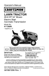
Figure 1 shows the snow [hrower completely assembled
TEE KNOB
CHUTE
CONTROL ROD
Reference to lhe dght and left hand side el the snow
thrower is from the operator position at the handle
FIG,, 1
LY
ASSE
L,L
'
TO REMOVE SNOW THROWER
TEE KNOB
FROM CARTON
UPPER HANDLE
@
Remove atlpacking
material
@
Remove a]l inserts located in the carton
DEFLECTOR
CHUTE
@ Locate and remove container ol Craftsman 2-cycle
oil
@ Remove chute control rod from insert and set aside
O
Cut down all four corners of carlon and lay panels fiat
TEE KNOB
@ Pull the snow thrower out of the carton
TO ASSEMBLE
@
THE HANDLE
Remove the wrap from the upper handle
@ Loosen the tee knob on the chute deflector (Fig 1)
@ Raise chute deflector to top position (Fig 2A) and
tighten tee knob
@ Loosen the tee knob on each side of the upper handle
(Fig 2)
¢
AUG
CONTROL
BAR
UPPER HANDLE
Pull the chute deflector to one side (Fig 2B) to clear
the upper handle and raise the upper handle to the
operating position as shown in Fig 1 (NOTE: Hold the
upper handle apart to prevent scratching the lower
handle)
¢_ Check to be sure the clutch cable is not caught in the
handle Tighten the tee knobs on the upper handle
FIG,, 2
CHUTE
DEFLECTOR
CHUTE
DEFLECTOR
UPPER
HANDLE
@ Loosen tee knob on the chute deflector and move it to
snow throwing position (Fig 1)
@ Tighten tee knob on the chute deflector
TO ASSEMBLE
TROL ROD
THE CHUTE CON-
@ Remove the screw and nut from the end of the chute
control rod and lay aside
@
Push the end of the chute control rod tllrough the hole
in chute control rod bracket on the lower handle (See
FIG. 2A
FIGo 2B
Fig 3)
@ Align the hole in the chute contro! rod wiltl tt_e hole in
the Iowerchute control rod (See Fig 31 Secure wilh
the screw and nut
O
Rotate the chute control rod tully clockwise and counlerclockwise The discharge chute should rolate freely
FIG. 3
OPERATIO
,i
,111
i
............................................................
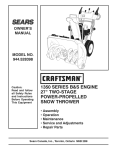
KNOW YOUR SNOW THROWER
READ THIS OWNER'S
MANUAL
AND SAFETY
RULES
BEFORE
THROWER.
Compare the illustrations with your snow thrower to familiarize
controls and adjustments, Save this manual for future reference,
OPERATING
YOUR
SNOW
yourself with the location of various
AUGER
CONTROL
BAR
UPPER
LOWER
HANDLE
CHUTECONTROLROD
RECOIL
CHUTE
DEFLECTOR
HANDLE
DISCHARGI
PRIMER
BUTTON
\\
STARTER
AUGE_
CONTROL
RECOIL
STARTER
_1
IGNITION
SWITCH
KEY
ASSEMBLY
AUGER
SCRAPER
HOUSING
BAR
FIG. 4
SEARS SNOW THROWERS conformto the safety standards of the American National Standards lnstitute,,B71.3-t984
,11,1
i,
ii
AUGER CONTROL BAR - Starts and stops the auger
which propels the snow thrower°
CHUTE CONTROL ROD. Changes the direction of snow
discharge.
CHUTE DEFLECTOR - Changes the distance the snow
is thrown
DISCHARGE CHUTE - Changes the direction the snow
is thrown
IGNITION SWITCH KEY - Must be inserted and turned to
the ON position to start the engine,
CHOKE CONTROL - Used to start a cold engine.
PRIMER BUTTON - Injects fuel directly into the carburetor manifold for fast starts in cold weather,,
RECOIL STARTER
HANDLE - Starts the engine
manually,
ELECTRIC STARTER BUTTON - Used to start the
engine using the 120 V electric starter
•OPERATION
The operalion of any snow lhrower can resufl in foreign objects being thrown into the
eyes, which can result in severe eye damage Always wear safety glasses or eye
shields while operating the snow thrower
We recommend standard safety glasses, available at SEARS Retail or SEARS
Service Center. or a wide vision safety mask for over your glasses
HOW TO USE YOUR
SNOW THROWER
TO STOP YOUR
O
TEE KNOB
SNOW THROWER
To stop the auger, release the auger control bar
NOTE: If the auger continues to creep, refer to the To
Adjust Auger Control Cable paragraph on page 14 and
15
•
To stop the engine, turn key to the OFF position
@ Turn the crank assembly to set the direction
snow throwing
TO CONTROL
@
SNOW
of the
DISCHARGE
Loosen the tee knob on the chute deflector and
move the deflector to set the distance
Move the
deflector UP !or more distance, DOWN for less
distance. Then tighten the tee knob (See Fig 5)
TO USE
AUGER
FIG, 5
PROPEL
AUGER
PROPELLE£
POSITION
_o_1_7
_'+
':\\;
ACTION
@ Squeeze the auger control bar down against the
upper handle to allow the auger to turn
@ To propel forward, raise the handle to allow the
rubber auger btades to contact the ground (See Fig
6)
/7' '
NORMAL
OPERATING
POSITION
AUGER BLADES
FIG,, 6
CAUTION:
READ
OWNER'S
MANUAL
BEFORE
OPERATING
MACHINE
NEVER
DIRECT
BYSTANDERS,
DISCHARGE
TOWARD
RELEASE
THE AUGER
CONTROL
BAR
AND STOP THE ENGINE
BEFORE
UNCLOGGING
DISCHARGE
CHUTE OR AUGER HOUSING
AND BEFORE
LEAVING
THE MACHINE
i,,,,, ,,i
ml,
i m
BEFORE
OP RATIO
!
STARTING
ENGINE
IMPORTANT:
WARNING: Experience indicates that alcohol blended
fuels (called gasohol or those using ethanol or methanol)
can attract moisture which leads to separation and formation of acids during storage. Acidic gas can damage
the fuel system of an engine while in storage. To avoid
engine problems, the fuel system should be emptied
before storage for30 days or longer. Start the engine and
let it run until the fuel lines and carburetor are empty, Use
the carburetor' bowl drain to empty residual gasoline from
the float chamber (See Fig_ 19)_ Use fresh fuel next
season. (See Storage Instructions on page 18 for additional information°)
The two cycle engine used on this snow thrower requires
a mixture of gasoline and oil for lubrication of the bearings
and other moving parts. The correct fuel mixture ratio is
40:1 (3.2 oz,. oil per gallon of gas - see Fuel Mixture
Chart), Gasoline and oil must be premixed in a clean
gasoline container, Always use fresh, clean, unleaded
gasoline._
U.S.
""'J
(Mixture
S.L(METRIC}
GAs O,LI GAS"
I OIL
[1 Gal.
_12 OZ.
GASOLIINE
40:1)
IMPERU_L'
jili'GaL
I 3.7
oz.,,
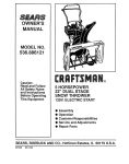
Reinstall the cap on the gasoline container and
shake container vigorously so the oil mixes with the
gasoline ,.
O
Add an additional 3 U_S quads of gasoline to the
gallon container and shake the container again
AND
CAUTION
MUST BE
USED WHEN
CAUTION:
GASOLINE
IS FLAMMABLE
HANDLING OR STORING IT. DO NOT
FILL FUEL TANK WHILE SNOW THROWER IS
RUNNING, HOT, OR WHEN SNOW THROWER IS
IN AN ENCLOSED .AREA. KEEP AWAY FROM
OPEN FLAME OR ELECTRICAL SPARK, AND DO
NOT SMOKE WHILE iVIIXING FUEL OR FILLING
FUEL TANK. NEVER FILL FUEL TANK COMPLETELY, BUT FILL THE TANKTO WITHIN 1/4- 1/
2 INCH FROM TOP TO PROVIDE SPACE FOR
EXPANSION OF FUEL. ALWAYS FILL FUEL TANK
OUTDOORS AND USE A FUNNEL OR SPOUT TO
PREVENT SPILLING. MAKE SURE TO WIPE UP
ANY SPILLED FUEL BEFORE STARTING ENGINE.
RLL GAS
MIX CHART
O
....._
Never' use engine or carburetor cleaner products in the
fuel tank or permanent damage may occur°
FUEL
DO NOT USE OUTBOARD MOTOR
OILOR AUTOMOBILE OILS, SUCH AS
SAE 30 OIL, OR MULTI-VISCOSITY
OILS, SUCH AS 10W-30 OR t0W-40
i
GAS"'IO,L
i
14L,!,ters
l OO.ML
I
AND OIL MIXTURE
Mix gasoline and oil (See Fig 7) as follows:
@ Pour I UoS quart of fresh, clean, unleaded
automotive gasoline into a gallon gasoline container
@ Add (3,2 oz) of clean, high quality, Craftsman twocycle oil to the gasoline container
STORE GASOLINE IN A CLEAN, APPROVED CONTAINER, AND KEEP CAP IN PLACE ON CONTAINER. KEEP GASOLINE IN A COOL, WELL
VENTILATED PLACE, NEVER IN THE HOUSE.
NEVER BUY MORE THAN A 30 DAY SUPPLY OF
GASOLINE TO ASSURE VOLATILITY. GASOLINE
IS INTENDED TO BE USED AS A FUEL FOR
INTERNAL COMBUSTION
ENGINES; THEREFORE, DO NOT USE GASOLINE FOR ANY OTHER
PURPOSE. SINCE MANY CHILDREN LIKE THE
SMELL OF GASOLINE, KEEP IT OUT OF THEIR
REACH
BECAUSE
THE
FUMES
ARE
DANGEROUS TO INHALE, AS WELL AS BEING
EXPLOSIVE.
DO NOT FILL THE FUEL TANK WITH GASOLINE THAT DOES NOT HAVE OIL MIXED IN IT. SHAKE THE
GASOLINE CONTAINER BEFORE EACH FILLING OF THE FUEL TANK
OIL
(112 CUP OR 32
'
! U,S GALLON
OZ )
SHAKE
CAN
+ I(L S-/ +
CONTAINER
FIG= 7
10
= ,@,
,
,
i
TO STOP ENGINE
OPEF ATJON
i
(Fig. 8)
PRIMER
i
RECOIL HANDLE
ELECTRIC
STARTER
BUTTON
@ To stopthe engine, turn the key to OFF and remove
key. Keep key in a safe place The engine will not
start without the key_
TO START ENGBNE
(Electric Starter) Fig. 8
The snow thrower engine is equipped with a 120 volt
A.Co electric starter and recoil starter Before starting the
engine, be certain that you have read the following
information:
COLD START
Q
i .....
Insert the key and turn ON
@ Move the choke control to FULL position
,
O
Connect the power cord to the switch box on the
snow thrower,
O
Plug the other end of the power
t20 volt A Co household receptacle,,
cord
into a
is 50 ° F to 15° F.
Four times if temperature
is below 15 ° F.
time, This electric starter is thermally protected_ If
overheated it will stop automatically and can be
restarted only when it has cooled to a safe
temperature (a wait of about 5 to 10 minutes is
required).
= = ,
, i=, ill
,H,,=rll,l=,r.n-i
NEVER RUN ENGINE
IN-
VENTILATED
ENGINE
EXDOORS OR IN AREAS.
ENCLOSED,
POORLY
HAUST CONTAINS CARBON MONOXIDE, AN ODORLESS AND DEADLY GAS.
As engine warms up and begins to operate evenly,
move choke lever slowly to OFF position if the
engine falters, return to 1/2 choke until it runs smoothly,
then move to OFF position.
ALWAYS
STAND
(OPERATOR'S
GINE.
BEHIND
SNOW
POSITION)WHEN
THROWER
STARTING EN-
DO NOT PUT HANDS, FEET, HAIR OR LOOSE
CLOTHING IN OR NEAR THE DISCHARGE CHUTE
DEFLECTOR OR AUGER HOUSING WHILE THE
ENGINE IS RUNNING° THE TEMPERATURE OF
THE MUFFLER AND NEARBY AREAS MAY EXCEED 150 ° F.; AVOID THESE AREAS.
NOTE: Allow engine to warm up for a few minutes before
using the snowthrower, as the engine wi!l not develop full
power until it reaches operating temperature
START
Move the choke to the OFF position and pull the
starter handle until the engine starts,
O
i,l=
CAUTION:
@ Disconnect the power cord from the receptacle first
and then from the switch box on the snow thrower.
WARM
, =
WHEN DISCONNECTING
THE 120 VOLT AC
POWER CORD, ALWAYS UNPLUG FROM THE
HOUSEHOLD RECEPTACLE FIRST.
@ Push down on the starter button until the engine
starts, Do not crank for more than 10 seconds at a
O
,
WHEN CONNECTING
120 VOLT AC POWER
CORD, ALWAYS CONNECT THE CORD TO THE
SWITCH BOX ON THE ENGINE FIRST, THEN
PLUG THE OTHER END INTO THE HOUSEHOLD
RECEPTACLE.
is above 50 ° Fo
Two times if temperature
i= ,H ,l= , =l=
......................
EQUIPPED
OPERATE
ON 120 VOLT
CAUTION: TO THIS
STARTER
IS
A
C
HOUSEHOLD
CURRENT.
FOLLOW
ALLINSTRUCTIONSCAREFULLYAS
SETFORTH
IN THE "TO START ENGINE" SECTION.
@ Push the primer button while covering the vent hole
as follows:(Remove finger from primer button between primes),
Do not prime if temperature
=
FIG° 8
Do not prime a warm engine If the engine fails to
start, follow the Cold Start instruclions above
11
,
ii
ii iiill,,,,i
TION
O
TO STOP ENGnNE (Fig. 8)
SNOW THROWING
TO stop the engine, turn the key to OFF and remove keyr
Keep key in a safe place° The engine will not starl without
the key.
@ This snow throwerwill propel itself forward when the
handle is raised enough to cause the auger blades to
contact the ground
TO START THE ENGINE
@
For most efficient snow throwing, turn the discharge
chute deflector to throw snow downwind, and slightly
overlap each swath. Use more overlap in deep snow
to prevent overloading
e
The distance snow will be discharged can be adjusted by moving the discharge chute deflectoL Raise
the deflector for more distance or lower the deflector
for less distance.
Move the choke control to FULL position.
0
Push the pdmer button while covering the vent hole
as follows: ( Remove finger' from primer button
between pdmes).
Irlwindy conditions, lower the chute deflector to direct
discharged snow close to the ground, where it is less
likely to blow into unwanted areas,
0
(Recoil Starter) Fig. 8
Before starling the engine, be certain that you have read
and understood all the instructions on the preceding
pages.
COLD START
Insert the key and turn ON1.
Keep the area to be plowed free of stones, toys and
other foreign objects Such items might be cover ed by
the first snow fall and picked up by the auger while
plowing.
DRY AND AVERAGE
SNOW
Do not prime if temperature is above 50°F.
Two times if temperature is 50 ° F_to 15 ° F
Four times if temperature is below 15° F
Remove finger from primer button between
primes..
@
Pult the starter hand!e with a smooth rapid movement. Do not allow the starter rope to snap back.
Rewind smoothly while holding the starter handle. If
the engine fires but does not start, pull the starter
handle until the engine starts..
@
After three pulls, repeat the priming and pulling steps
again..
@
As engine warms up and begins to operate evenly,
move choke lever slowly to OFF position, tf the engine
falters, return to 1/2 choke until it runs smoothly, then
move to OFF position.
TiPS
@
Snow up to eight inch depth can be removed rapidly
by walking at a moderate rate For snow or drifts of
a greater depth, you may find it desirable to slow your
pace to allow the discharge chute to dispose of the
snow as rapidly as the auger receives the snow..
@
Plan to have the snow discharged in the direction the
wind is blowing.
WET PACKED
@
NOTE: Allow the engine to warm up for' a few minutes
before using the snow thrower, as the engine will not
develop lull power until it reaches operating temperature.
Move slowly into snow of this condition.. The greater
the depth, the slower you should go.. When it appears
that the wet, packed snow is causing the auger to
slow down and the chute to clog, back off and begin
a series of short jabs into the snow.These short back
and forth, 4 to 6 inch jabbing motions will "belch" the
snow from the chute°
SNOW
WARM START
SNOW
BANKS
AND DRIFTS
@ In snow of greater depth than the unit, use the
"jabbling" technique described above Turn the discharge chute away from the snow bank. More time
will be required to remove snow of this type than level
@ Move the choke to the OFF position and pull the
starter handle until the engine starts_
@ Do not prime awarm engine. Ifthe enginefailsto start,
follow the Cold Engine Start instructions above.
snow,,
ROCKS OR OTHER DEBRIS, IF STRUCK
CAUTION: OBJECTS SUCH AS GRAVEL,
BY THE AUGER, MAY BE THROWN WITH
SUFFICIENT
FORCE TO CAUSE PERSONAL INJURY OR PROPERTY DAMAGE.
12
REGISTROS
Llene
las fechas
que complete
FECHAS DE SERVIC!O
PROGRAMA
DESERVIClO
a medida
Antes
su servicio
de
regular
cada
use
Despu_
De
deles
acuerdo
a lo
12
necesario
Horas
Antes del
Antes
Cada
del
_lmacena temporada
"niento
Apretar redes lostorni}los y tuercas
/
Apretar bujia
Apretar las coffees impulsoras
Apretar combustible
Droner combustible
Lubricar la bride de contro_del canal
REMOVEDORA
TABLA DE LUBRICACION
DESPUES
Lubrique la bride de control del
canal de descerga,r Remueva el
canal de descarga y cubra la brida
cln una grasa ripe adhesive come
Lubriplateo
DE NIEVE
DEL PRIMER
use
O
Examine tadas las piezas para var si ast&n sueltas o
daSadas, despu_s de cada vez que use la unidad
O
Ajuste todos los pemos que est_n ftojos
DESPUES
DEL CADA
use
O
Haga funcionar ta unidad haste que expulse toda la nieve
y quede limpio el barreno
O
Retire de la removedora cua_quier resto de nieve o fango
para evitar la congelaciSn del barreno y los controtas
LUBRICAC|ON
- SEGUN
SE NECESlTE
O
Lubr_que la bride de_canal de descarga antes de guarder
la unidad
O
Consultela"Tabta de lubricaciSn"para obtener informaci6n
sobre los puntos de aceite y el tipo de tubricante a usar
MOTOR
BUJIA
RECOMENDACIONES
GENERALES
La garantla de esta removedora de nieve no cubra elementos
que han estado sujetos a abuse o negtigancia de! operador
Para recibir el valor total de la garant[a, el operador deber& dar
mantanimiento ala ramovedora de nieve de acuerdo a las
instrucciones contenidas an este manual
Se necesitar& efectuar algunos ajustes periSdicamente
mantener apropiadamente su removedora de nieve
para
Todos los ajustes an la secci6n Servicio y ajustes de este
manual daberian ser verificados per lo menos una vez durante
fa estaci6n
13
O
Peri6dicamente, limpie la bujia y calibre su abertura. Pare
darle servicio o reemplazar la bujia, consulle _a secci6n
"Cambio de la bujia" en la p&gina 17
O
Aseg_rase de que la bujia est_ cotocada apropiadamente
en el motor y conectada al cable respective
O
Si cuenta con una Itave de torque (dinamometrica), ajuste
la bujia entre I8 y 23 pie_libras (entre 2,48 y 2,76
kifogr&metros)
O
Antes de remover la bujia, limpie el ;_rea a su afrededor
para evitar que ning0n sucio o particula extraP,a caiga en
et interior del motor inch
.........................
S
AJUSTE
E
_V
_
C
_
O
Y AJUSTES
,,,,
DEL CARBURADOR
H ill ,i
i,i,
MANIJA DE
CONTROL
DELBARRENO
El carburador de esta removedora de nleve no es de! tipo
ajustableo
IMPORTANTE: SI USTED CREE QUE EL CARBURADOR
NO
ESTA
FUNCIONANDO
ADECUADAMENTE,
COMUNIQUESE CON SU CENTRe DE SERVICIOS SEARS
MAS CERCANO
MANGA
ALTERAR
LAS CONDICIONES
DEL
PRECAUCION:
TRATE
REGULADOR DEL NUNCA
MOTOR PUES
ESTE DE
HA
SIDe COLIBRADO
EN FABRICA PARA
BRINDAR LA VELOCIDAD NECESARIA. EL EXCESO
DE VELOCIDAD DEL MOTOR PUEDE AUMENTAR EL
PELIGRO DE LESIONES PERSONALES ADEMAS DE
ANULAR LA GARANTIE SOBRE EL MOTOR. SI CREE
QUE EL REGULADOR DE VELOCIDAD REQUIERE DE
UN AJUSTE
EN ALTA, COMUNIQUESE
CONEL
CENTRe DE SERVICIOS SEARS MAS CERCANO,
DONDE OBTENDRA EL EQUIPO Y LA EXPERIENCIA
ADECUADOS
PARA REALIZAR
LOS AJUSTES
NECESARIOSo
come AJUSTAR EL GRUPO
MANIVELA
DE DESCARGA
FIG, 10
TUERCA
DE
EL CABLE
DE LA
CABLE
FIG. 11
POLEA
DE
TRACCION
POLEA
TENSORA
DE CONTROL
El cable de control del barreno ha side ajustado en la planta
para brindar el nivel de operacibn apropiado
Si necesita
ajustar el cable a la tensi6n de operaclon apropiada, proceda
de ]a siguiente forma:
e
ENHEBRAR
DE
VARILLA
ACERO",-_
ASTA
El grupo de la manivela de descarga ha side calibrado on la
f&bricay nodeberiasernecesadoajuste
alguno Sin embargo,
si no est& funcionando adecuadamente, ileve su removedora
de nieve a un Centre de Servicios Sears autorizado para su
reparaci6n y ajuste
come AJUSTAR
DEL BARRENO
EXTREMO EN
GANCHO
MANGA
/
Deslice la manga protectora del resorte hacia el extreme
en forma de gancho, dejando a la vista la secc{Sn con
rosca y la tuerca de ajuste (vea la Fig 11 )
@
Afloje ta tuerca con una llave de 9,5 mm (3/8 pulgada)
mientras sujeta el mango de acero con un alicate
e
Sujete la secci6n con rosca y gire el mango de acero hasta
que elimine la holgura del cable y est_ m&s tense (vea la
Fig 11)
ALOJAMIENTO
DEL BARRENO
Vuelva a apretar Eatuerca contra et mango de acero
@
Vuelva a colocar ]a manga protectora sobre e[ resorte de
tensi6n
e
Encienda ta removedora de nieve y verifique que el
barreno deje de girar al soltar la manija de control
@
Si el ba_reno continua gii'ando, afioje la tuerca y gire e!
mango de acero 2 8 3 vueltas para distender el cable;
luego, apdete nuevamente la tuerca contra el mango de
acero usando las mismas herramientas (yea ta Fig 11)
TECTOR DE LA
CORREA
FIG. 12
NOTA: No ponga demasiada tensi6n on el cable o no podr_
desenganchar el embrague
G
POLEA
DEL
BARRENO
14
SERVICEAN
p
, L
_UU I,
I, I
ADJUSTM
TS
I
Star! the snow thrower and check that the auger
does not continue to turn when the auger control bar
is released.
BELT GUIDE
(Right
BELT COVER
@
Remove the belt cover (see Fig, 12 on page 14) by
removing the 7 screws
@
Pull the belt cover away from the snow thrower
TO ADJUST
Hand)
IDLER PULLEY
@ If auger continues to turn, loosen nut and twist steel
shank 2 or 3 turns to loosen cable and then tighten
nut against steel shank using the same tools (See
Fig 11),
TO REMOVE
ENGINE
PULLEY
PULLEY NUT
THE DRIVE BELT
TENSION
BELT GUIDE
(Left Hand)
The auger drive belt tension is set at the factory If the
snow discharge distance decreases, do the following:
@
Remove the (3) screws from the access panel on
the rear of the top cover.
@
Disconnect the spark plug wire.
FIG. 13
@ Remove the belt cover (See to Remove the Belt
Cover paragraph)..
@
lnstallthe
new belt
@ Loosen but do not remove the nut on the idler pulley
@ Adjust the belt guide gaps See To Adjust the Bell
Guides paragraph on page 16
@ Move the idler pulley to the bottom of the idler arm
slot Tighten the nut
@
@ Reconnect the spark plug wire
NOTE: If the idler putley is already in the bottom position,
replace the belt.
@ Start the snowthrower and check tl3at the auger does
not continue to turn when the auger conlrol bar is
released
TO REPLACE
@
If auger continues to turn, loosen nut and twist steel
shank 2 or 3 turns to loosen cable and then tighten
nut against steel shank
@
Reinstall the bell cover
THE DRmVE BELT
The drive belt on this unit is of special construction and
must be replaced with the same type belt available at
your nearest SEARS Service Center
@ Remove the (3) screws from the access panel on
the rear of the top cover
@ Disconnect the spark plug (See page 17)
@ Remove the belt cover (See to Remove the Belt
Cover paragraph on page 14)
@ Loosen the nut on the bell guides
@ Movethe guides away fromthe v-beR and rollthe belt
off of the idler pulley.
@ Carefully press the idler pulley down and rmove the
v-belt from under the brake on the auger pulley and
roll the v-belt off of the auger pulley and the engine
pulley
@ Remove the old belt
@ Loosen the nut on the idler pulley
@ Move the idler pulley to the top of the idler arm slot
Tighten the nut
15
Reconnect spark plug wire and replace access cover
(See Fig 17on page 17)
ADJUST
SERVICE
i
ii
TO ADJUST
ii
TS
IINNI"IIIIIIIIIIINIHII"IIHIIHHHHHI""HH"HI
'
THE BELT GUIDES
There are two belt guides on your snowthrower Afteryou
replace an auger drive belt, you need to adjust one or
both of the belt guides (See Fig 14) Proceed as follows:
O
Remove the (3) screws from the access panel on
the rear' of the top cover
@ Disconnect the spark plug wire
@ Remove the belt cover (See to Remove the Belt
Cover paragraph on page 15)
•
Engage the auger control bar,
®
Measure the distance between the belt guides and
the belt, The distance should be 1/8" for each guide
@ If adjustment is necessary, move the belt guides to
the correct position, (See Fig 14)
O
Move the belt guides to the correct position
e
Release the auger control bar,
e
Reinstallthe
e
Reconnect the spark plug wire and reinstall the
access panel
(Left Hand)
belt cover,
TO REPLACE
THE SCRAPER
If the scraper blade must be replaced
proceed as follows (See Fig 15):
FIG,, 14
BLADE
due to wear,
@ Remove 4 nuts, 4 bolts and scraper blade
e
Install new scraper blade, 4 nuts, and 4 bolts
BOLTS
SCRAPER
BLADE
NUTS
FIG. 15
16
I
'
SERVICE AN
M
ADJUSTM
...................
ii
i
TS
, i,i u ,J,, ,JJlI_,I,,L
TO REPLACE THE AUGER
@
Remove the (3) screws from the access panel on the
rear of the top cover
@
Disconnect the spark plug wire.. (See To Replace
Spark Plug section)
@
Remove the belt cover (See To Remove Belt Cover
paragraph on page 15) and the drive belt. See the
Drive Belt Replacement paragraph on page 15
@
Remove the augerpulley (See Fig. 16) fromthe auger
shaft (threads are left hand; turn clockwise to remove
and place a piece of wood (2"x4") on the center paddle
area to secure the auger to keep it from turning)
NOTE: (When unscrewing the puiley hold the idler
pulley down).
BEARING
ASSEMBLY
AUGER
PULLEY
AUGER
ASSEMBLY
FIG. 16
@ Remove the bearing assembly from the left frame of
snow thrower by removing the (2) nuts
ACCESS
@ Slide the auger assembly out of the bearing assembly
on the right side of the snow thrower.
PANEL
@ Tip the auger assembly enough to allow it to slide out
of the front of the auger housing
TOP COVER
/
OVER
\\
?22'#?
@ Install lhe new auger assembly in reverse order of
removal..
@
SPACER
LEFT FRAME
Reconnect the spark plug wire and reinstall access
panel
NOTE: Check the drive belt adjustment before reinslalting
the belt cover (see To Adjust the Drive Belt paragraph on
page 15)..
_
COVER MOUNTING
SCREWS
TO REPLACE THE SPARK PLUG
VIEW FROM OPERATOR'S
The spark plug is housed in the engine compartment under
the top cover (See Fig. 17) and cannot be seen under
normal conditions_
POSITION
FIG. 17
@ Remove the 3 screws from the access panel on the
rear of the top cover
@ Remove the spark plug wire
@ Clean the area around the plug base to prevent dirl
from entering the engine when the plug is removed
@
Remove the spark plug If it is cracked, fouled or dirty,
it must be replaced (see page 4 for the proper replacement plug).
@ Set the gap between the electrodes ol the new spark
plug at .030 inch.. Next, install the spark plug in the
cylinderhead Tighten the plug to 18 to 20 foot pounds
If you do not use a torque wrench, tighten the plug
firmly (See Fig 18)_
FIG. 18
ADJUST
@ Push the spark plug wire onto the spark plug
®
ENGINE SPEED
Your engine speed has been factory set Do not attempt
to change engine speedor it may result in personal injury
if you believe that the engine is running too fast or too
slow, take your snow thrower to an authorized Sears
Service Center for repair and adjustment
Reinstall the access panel to the top cover
ENGINE SERVICE
Unless the operator is fully qualilied to make engine
repairs or adjustments, we recommend that such work be
done by technicians trained to work on snow thrower type
engines Take your snow thrower to an authorized Sears
Service Center for repair and adjustment
17
STORAGE
iJ,llll,
iii
iiii
IIHIIII
,H
THROWER
INDOORS
ORYOUR
tN AN
ENCAUTION: NEVER
STORE
SNOW
CLOSED, POORLY VENTILATED AREA
IF GASOLINE REMAINS IN THE TANK° FUMES
MAY REACH AN OPEN FLAME, SPARK OR PILOT LIGHT FROM A FURNACE, WATER HEATER,
CLOTHES DRYER_ CIGARETTE, ETC.
BOWL DRAIN
To prevent engine damage (if snow thrower is nol used
for more than 30 days) follow the steps below
SNOW
THROWER
R_GHT SIDE VIEW
OF ENGINE
STORAGE
@ Thoroughly clean the snow thrower
O
Lubricate all the lubrication points (see the Customer
Responsibilities section, page 13)
Q
Be sure that all nuts, bolts and screws are securely
fastened. Inspect all visible moving parts for damage, breakage and wear Replace if necessary.
O
Touch up all rusted or chipped paint surfaces; sand
lightly before painting
FIG. 19
You can keepyourengine
during storage by:
Q
@ Cover the bare metal parts of the blower housing and
auger with rust preventative, such as sprayable
lubricant
ENGINE
Lubricating the piston/cylinder area This can be
done by first removing the spark plug and squirting
clean engine oil into the spark plug hole Then cover
the spark plug hole with a rag to absorb oil spray
Next, rotate the engine by pulling the starter two or
three times Finally, reinstall spark plug and attach
spark plug wire.
OTHER
STORAGE
O
Gasoline must be removed or treated to prevent
gum deposits from forming in the tank, filter, hose,
and carburetor during storage. Also during storage,
alcohol blended gasoline that uses ethanol or methanol (sometimes called gasohol) attracts water, it acts
on the gasoline to form acids which damage the
engine.
@ To remove gasoline,runthe engine untilthe tank is
empty and the engine stops Then drain remaining
gasoline from carburetor by pressing upward on
bowl drain located on the bottom of carburetor (See
Fig 19)
O
in good operating condition
If possible, store your snow thrower indoors and
cover it to give protection from dust and dirt
@ If the machine must be stored outdoors, block upthe
snow thrower to be sure the entire machine is off the
ground
@ Cover' the snow lhrower with a suitable protective
covet that does not retain moisture Do not use
plastic or vinyl
NOTE: A yearly checkup or tuneup at a Sears Service
Center is a good way of ensuring that your snow thrower
will provide maximum performance for the next season
If you do not want to remove gasoline, a fuel stabilizer
(such as Craftsman fuel stabilizer No 33500) may be
added to any gasoline left in the tank to minimize
gum deposits and acids If the tank is almost empty,
mix stablilizer with fresh gasoline in a separate
container and add some to the tank. ALWAYS
FOLLOW INSTRUCTIONS ON STABILIZER CONTAINER. THEN RUN ENGINE AT LEAST 10 MINUTES AFTER STABILIZER IS ADDED TO ALLOW
MIXTURE TO REACH CARBURETOR_ STORE
SNOWTHROWER IN A SAFE PLACE. SEE WARNING ABOVE.
18
=tROUBLESHOOTRNGPOINTS
ii. i-i
n
n
,
iii
ii
IIUUUIILIIL
I
IIIII
IIIII
I
IIIII
i
III
i,
TROUBLE
CAUSE
CORRECTION
Difficult starting
Defective spark plug
Replace defective
Engine stalls
Unit running on FULL choke
Set choke lever to OFF position
Engine runs erratically;
Blocked fuel line or tow on fuel
Clean fuel line; check fuel supply; add fresh
plug
gasoline (oil mixture)
Loss of power
Use carburetor
Water or dirt in fuel system
bow] drain to flusb and refilt with lresh
fuel
Carburetor
See carburetor
out of adjustment
adjustment
section on page t4
lUllU
Excessive
vibration
Stop engine immediately
Loose parts; damaged impeller
and disconnect
Tighten al! bolts and make a{I necessary
continues,
l llul ,nHml
Unit fails to
discharge
If vibration
have the unit serviced by a competent repairman
Repair or reptace auger assembly
Damaged auger
Unit fails to propel
itself
spark plug wire
repairs
ii ii
Drive belt loose or damaged
Replace drive belt
Incorrect adjustment
Adjust auger control cable
el auger control cable
Auger drive belt loose or damaged
Adjust auger drive belt; reptace if damaged
Auger control cable not adjusted
Adjust auger control cable
snow
correctly
Stop engine immediately
Discharge chute clogged
and disconnect
spark plug wire
Clean discharge chute and inside of auger housing
Stop engine immediately
Foreign object todged in auger
and disconnect
Remove object {tom auger
19
spark plug wire
CRAFTSMAN
,tu
,
llll
21" SNOW THROWER
lllll
536.884670
!
it,H,,u u
ENGINE AND DRIVE REPAIR PARTS
12
[lllll;rJ[_iflll,
REF.
NO,
iiiiiiii
PART NO.
1
2
3
4
5
6
7
8
9
10
11
12
13
14
181593
120638
301418
318472
310176
320150
41529
301415-830
180073
1498
301856
312502
320529
REF.
NO.
PART NAME
Engine, Model 143.944571
(See Engine Repair Parts List)
Screw, HHC, 5/16-24 x 5/8 In
Lockwasher, Split 5/16 In
Bracket, Idler Arm
Bolt, Idler Arm
Spacer, Pivot, 3/8 tn
Brake Spring, Torsion
Locknut, Jam, 3/8-16 Thd
Bracket, Engine Support
Screw, HHC, 5/16-18 x 1/2 In
Locknut, Hex, 5/16-18 Thd
Pulley, Idler
Boil, Carriage, 3/8-16 x 1-t/4 In
Cable, Drive Control
15
16
17
t8
19
20
21
22
23
24
25
26
27
28
PART NO.
70971
120392
1502
314142
313595
45602
300637
325890
313244
313243
180122
120394
1499
334014
PART NAME
Screw, HHC, 1/4-20 x t-1/2 In
Flatwasher, 1/4 In
Locknut, Hex, 1/4-20 Thd
Cover, Cable Spring
Pulley Half
Flatwasher, 5!16 In
Screw, Hx Nyl, 5/16-24 x 7/8 In
V-Belt
Guide, Belt
Guide, Belt
Screw, HHC, 3/8-16 x 1 In
Flatwasher, 406x 81x 066
Nut, 318-16 Reghxctrlk
Owner's Manual
320459 B
2O
CRAFTSMAN
21" SNOW THROWER
FRAME COMPONENTS
536.884670
REPAIR PARTS
REF. KEY #8
4
8
14
11
'17
3
17
REF. KEY #18
PAGE 23
18
10
REF. KEY #1
PAGE 23
23
21
22
10
REFo
NO.
PART NO.
1
2
3
4
5
6
7
8
9
!0
11
12
301420-830
301421-830
3'11738-830
302414
46931
180073
1498
30!419-830
307724-830i
309814
326142
327019
22
REF.
NO,
PART NAME
13
14
15
16
17
18
19
20
21
22
23
24
Rear Mount Plate, R H
Rear Mount Plate, L H
Heat Shield, Engine
Screw, 1/4-20 x I/2 In
Nut, WdFILk, 1/4-20 Thd
Screw, Hex, 5/16-18 x 1/2 In.
Nut, Lk 5/16-18 Thd
Support, Engine Mount
Bracket, Fuel Tank
Screw, Tap, #10-24 x 5/8 In
Fuel Tank
Cap, Fuel with Seat
PART NO.
323363
47345
56679
323395
323387
274707
997316
311671
302287
303041
313057
57366
24
PART NAME
Gas Line, 8 0 In
Clamp, Hose
Filter, In-Line
Gas Line, 30 In
Clamp, Fuel Line
Screw, #10-24 x 1/2 tn
Nut, #10-24
Clamp, Worm
Shroud, Bottom
Flatwasher, 203x 56x 040
"S" Clip
Screw, #t0-16 x 50 Drilltite
320530 B
21
CRAFTSMAN
................
i1,1 ,,
ii
21" SNOW THROWER
_lll
i
,,i
i
i i
,,
,
,
i,
536.884670
,
i
,
,,,
ELECTRIC STARTER REPAIR PARTS
REF. KEY ,#3
PAGE 23
REF:
NO.
PART NO.
t
2
3
4
5
57569
311633
414106
271163
56023
PART NAME
Wire Retainer
Screw, #8-32 x 3 k_
Flatwasher, t88x 38x 040
Nut, Hex Keps, #8-32
Extension Cord
313974
A
BELT COVER REPAIR PARTS
REF.
NO.
PART NO.
PART NAME
NO.
PART NO.
PART NAME
1
2
3
4
5
6
7
8
9
10
302416-830
35258
307468
309814
303041
309813
120385
309811
57587
333643
Cover, Belt
Screw, #10-24x318 In
Cover, Top
Screw, #10-24x518 In
Flatwasher, 203x 56x 040
Screw, #10-14x5/8 In
Flatwasher, 250x 56x 049
Nut, Tinn "U" Type
Grommet & Washer, Rope Guide
Knob, Rope
11
12
13
14
!5
16
17
18
19
20
56992
138557
48140
49643
54601
t259
303008
307469-830
307470
312362
Switch, tgnition
Washer, ReglniLk
Nut, tgn Hex, 5/8-32 Thd
Key & Ring Assembly
Primer, Engine
Hose, Primer, 5 76 in Lg
Nut, Hex Keps, t14-20 Thd
Bracket, Shroud Mounting
Door, Access, Plaslic
Screw, #10-16x3/4 In
313976
22
C
CRAFTSMAN
21" SNOW THROWER
536.884670
AUGER HOUSING REPAIR PARTS
6
7
3
11
4
13
8
REF.
NO.
'1
2
3
4
5
6
7
8
9
10
11
12
13
PART NO.
PART NAME
330317-830
302418
55686
46931
54837
180021
'120392
3O9376
49562
180020
1502
302428
301855
Auger Housing, 21"
Blade, Scraper
Screw, 1/4-20x5/8 in
Nul, WdF]Lk, 1/4-20 Thd
Bearing, Flange
Screw, Hex, 1/4-20x7/8 In.
Flatwasher, 286x 63x.065
Auger Assembly, 21"
Bearing, Ball
Screw, Hex, 1/4-20 x 3/4 In.
Nut, Hex Lock, 1/4-20 Thd.
Spacer, Sle 640X 88X732
Pulley, V3L
3t4349
23
B
CRAFTSMAN
DISCHARGE
21" SNOW THROWER
536.884670
CHUTE REPAIR PARTS
8
10
11
13
12
1
23
./22
24
21
3
25
22
23
10
REF.
NO.
1
2
3
4
5
6
7
8
9
10
11
12
13
PART NO.
302500
56962
300790
307693
180016
46931
307665
308931
302843
120393
13527
120376
58208
REF.
NO.
PART NAME
14
15
16
17
18
19
20
21
22
23
24
25
Ring, Lower Chute
Screw, WaTap,1/4-14x5/8 In
Clip, Chute Ring
Chute, Lower
Screw, Hex, 1/4-20xl/2 In
Nut, WdFILk, 1/4-20 Thd
Chute, Upper
Wire, Chute Hinge
Bolt, Cart, 5/16-18xl 25
Flatwasher, 349x 69x 066
Knob, Tee
Nut, Hex, 5/16-t8 Thd
Screw, 5/16-18x3/4 In
PART NO.
1498
302505-830
998013
120368
300728-830
307741
1502
307742
12452
121222
51564
313431
PART NAME
Nut, Lock, 5f16-18 Thd
Bracket, Worm Adjusting
Bolt, 5/16-18x 75
Washer, Split lock
Bracket, Chute Rod
Plate, Chute Rod
Nut, Lock, 1/4-20 Thd
Rod Assembly, Lower Chute
Flatwasher,
40x 75x 025
Pin, Cotter
Block, Pivot
Washer, Curved
3_4355
24
|;
CRAFTSMAN
21" SNOW THROWER
536.884670
WHEEL REPAIR PARTS
6
5
REFo
NO,
PART NO.
1
2
3
4
5
6
307719
309656
325016
120394
26178
36832
PART NAME
Shaft, Axle
Spacer Slev 407x 63x 440
Tire & Rim 8xl 75
Flatwasher, 406x 81:<,066
E-Ring
Hub Cap
3t 3979 B
HANDLE ASSEMBLY
REPAIR PARTS
,/
6
7
REF., KEY #1
PAGE 21
\
4
2
=-'
!i
10
9
REF. KEY #8
PAGE 21
REE
NO.
1
2
3
4
5
6
7
8
PART NO,
301608-830
311767
22025
13527
120376
302417-830
301607-830
180077
REE KEY #2
PAGE 21
_:
REF.
NO.
PART NAME
I Handle, Upper
Bolt, 5/t 6-I 8xl -3/4 In
Washer, Formed
Knob, Tee
Nut, Hex, 5/16q8 Thd
Bar, Drive Control
Handle, Lower
Screw, Hex, 5/t6-18x3/4
9
!0
11
12
13
14
15
PART NO.
120393
1498
308715
308716
997316
309815
310169
PART NAME
Flatwasher 349x 69x 066
Nut, Hex, 5/16-18 Thd
Bracket, Chute Crank
Bracket, Chute Crank
Nut, Lock, #10-24 Thd
Screw, #10-24xl In
Screw, Tap, !/4-20×5/8 Thd
tn
3"i3980 D:
25
CRAFTSMAN
21" SNOW THROWER
536.884670
i
i,i i ii
DECALS
9
\
5
REAR VIEW
(TOP SHROUD)
7
REFo
NO.
PART NO.
PART NAME
illl,
I
2
3
4
5
6
7
8
9
308778
310151
70141
334150
313295
313296
318494
313892
308768
6
t l
Decal,
Decal,
Decal,
Decal,
Decal,
Decal,
Decal,
Decal,
Cecal,
,, ,,,,,u
n nl
Craftsman
Craftsman
Danger Auger
5/21 Sears
Start Instruction
Control Panel
Choke
Danger Chute
Danger Stripe Chute
3t9112B
=_
_1.,.ii
i
i i
i,,u,,,,,uu
26
i.i
ii
CRAFTSMAN
iiiii iii
iii
i
21" SNOW THROWER
536.884670
ii
CHUTE CONTROL ROD REPAIR PARTS
4
REF. KEY #24
PAGE 24
REF, KEY #24
PAGE 24
PART NO.
[u,
i,,,
PART NAME
ii ii
307756
t 2452
t 21222
309449-830
314158
314159
307755
331532
Rod, Middle Chute
Flatwasher 40x 75x 025
Cotter Pin
Rod, Upper Chute
Screw, #10-32 x 7/8 In,
Nut, #10-32
Knob, Chute Crank
Cap Nut, Push-On
313981B
27
CFIAFTSMAN 2-CYCLE ENGINE
i
ill.
ii
l i.H,i
MODEL NUMBER143.955071
li.Nl,,i
, i ..,.i
27
23
22
30
20
138
177
t6
7BA
28
/
.,,,,
,
H ,,,i,,i
CRAFTSMAN
KEY#
1
16
16A
19
19A
20
21
22
23
24
27
29
30
35
35A
37
39
42
75
75A
80
89
90
92
93
100
!01
103
105
I06
135
t38
t77
184
186
187
217
218
239
260
261
274
275
277
285
287
325
330
350
351
361
370
380
383
384
390
395
399
2°CYCLE ENGINE
PART#
250295
490317
490304
490320
490318
510340
570673
510338
530158
530161
530159
530164
290627
29826
650961
29216
310277B
3'10278
510339
510337
490305
611191
611192
650815
650816
34443A
6'10118
650814
650892
650891
611049
570683
650959
510326A
490319
570438A
570667A
650847
35815
350441
650894
510343A
390325
650893
34449
650926
611034
61'1158
570629A
32180C
30063
35977
632642
570695
650229
590652
590670
510334
DESCRIPTION
MODEL NUMBER143.955071
QTY
Cylinder Ass'y. (IncL 75A, 105, 106, &138) .......
1
Governor Lever ...............................................................
1
Governor Lever ..........................................................
1
Extension Spring ....................................................
1
Throttle Link Spring .........................................................
1
Oil Seat
1
Ball Bearing ......................................................................
3
Slide Ring
1
Ball Bearing ..................................................................
1
Ball Bearing ..................................................................
1
Bearing Retainer .....................................................
1
Bearing Strip (31 needles) .....................................
1
Crankshaft
1
Screw,. 10_32 x 3/4".
1
Screw, 4-40 x 1/4" .....................................................
2
Lock Nut, 10-32 ..........................................................
1
Piston & Rod Ass'y. (lncL 29 &42) ......................
1
Ring Set ..............................................................................
1
Oil Seal
1
Oi! Seat ...................................................................................
1
Governor Shaft ...........................................................
1
Flywheel Key ...............................................................
1
Flywheel ...........................................................................
1
Belleville Washer ..............................................................
1
Flywheel Nut ....................................................................
1
Solid State Ingnition .................................................
1
Spark Plug Cover .....................................................
1
Screw Torx T-!5,10-24 x 1". .........................................
2
Screw, 5/16-18 x 2-3/16". .....................................
2
Screw, 5/16-18 x 1-5/8 ...............................................
2
Resistor Spark Plug (RCJ8Y) .............................2
Port Cover
2
Screw, 5/32 Allen, 1/4-20 x 1". ..................................
2
Carburetor Gasket
2
Governor Link ....................................................................
1
Spacer .............................................................................
1
Control Lever ...................................................................
1
Screw, 8-32 x 1/2". ......................................................
1
Air Cleaner Gasket ........................................................
1
Blower Housing ...............................................................
1
Screw, 5/16-18 x 5/8". .................................................
4
Exhaust Gasket ...............................................................
1
Muffler ..............................................................................
1
Screw, 5/16-18 x 3-13/64". ........................................
2
Starter Cup ..........................................................................
1
Screw, 8-32x 21/64". ................................................
3
Wire Clip
1
Wire Harness
1
Primer Ass'y
1
Primer Line .....................................................................
1
Screw, torx T-30, 1/4-20 x 1/2" ..............................
3
Caution Decal ..................................................................
1
Carburetor (Incl. 184) .................................................
1
Spit Cup .......................................................................
1
Screw, Torx T-25, 10-32 x 3/8" _............................
2
Rewind Starter .............................................................
I
Electric Starter Motor
1
Gasket Eliminator (Loctite 515) ...................................
1
.................................................................................
......................................................................
.................................................................
.......................................................
..........................................................................
....................................................................
.........................................................
...............................................................................
..............................................................
.......................................................................
............................................
29
CARBURETOR
,,.._=_11
,i,
i!l
NO. 632642
.........
i
i iiii
r_
il
i,
_
, i,i1,,i
I
i
"_4
6
6/'
27
3O
.......
i,
,,i,,
,_
KEY#
PART#
DESCRIPTION
.................................. QW
1
6
7
t0
14
15
16
25
26
27
28
29
30
31
32
33
40
44
48
632538
631621
650506
632566
631815
630735
632164
631951
632396
631024
632019
631028
631021
631022
27136A
27554
632503
27110
631027
Throttle Shaft & Lover Assembly ........... 1
Throttle Shutter ...................................... 1
Shutter Screw .....................................
2
Choke Shaft & Lever Assembly ...............!
Choke Shutter .................................
1
Choke Positioning Spring .......
1
Fuet Fitting ...............................
1
Float Bowl Asy (Incl 32&33) .......
t
Float Dampening Spring ................
1
Float Shaft ............................................... 1
Float
...............................
1
Float Bowl "O" Ring ................................ !
inlet Needle, Seat & Clip (Incl 31 )
1
Spring Clip ..................................
1
Bowl Drain Assy ........................
1
Drain Plunger Gasket ...................................
1
High Speed Bowl Nut .................
1
Bowl Nut Washer ..................
t
Welch Plug, Atmospheric Vent ........... t
KEY#
PART#
DESCRIPTION ............................... QI"Y
1
2
3
4
5
6
7
8
9
t0
11
12
13
590599A
590600
590615
590601
590598
590616
590617
590645A
590619
590620
590643
590535
590452
Spring Pin
Washer
Retainer
Washer
(Incl 4) .......................
...............................
..............................................
.........................................
1
1
1
1
Brake Spring .............................
t
Starter Dog .....................................
2
Dog Spring
2
Pulley Ass'y (loci 9&10) ..............
1
Rewind Spring ......................................
1
Spring Covet' . ..........................
!
Starter Housing Ass'y ............................... 1
Starter Rope (Length 98" x 9/64" dia ) 1
Starter Hndle .....................................
1
.......................................................
STARTER MOTOR NO 590670
I
\
_9
QTY
Retainer Ring ...............................................................
1
Dust Washer .................................................................
1
Pinion Driver ..............................................................
1
Anti-drift Spring ........................................................
t
Gear
1
AntFdrift Spring .........................................................
1
Spring Retainer
1
Cup Washer
1
Retainer Ring
1
Drive End Mounting Bracket ............................ 1
Drive End cap Ass'y ....................................................
1
Armature
Thrust Spacer
1
Housing Ass'y ................................................................
1
Brush & Spring Card Ass'y .....................................
1
Commutator End Cap Ass'y ..................................
t
Commutator End Mounting Bracket ...................1
Case Bolt .............................................................................
2
Lock Nut ..............................................................................
2
Switch Box & Lead Ass'y
1
Extension cord (I0'6") .............................................
1
Screw, Torx T-3, 1/4-20 x 1/2", ............................
3
Screw, 6-32 x 2-1/2" ...............................................
2
Nut & Washer Ass'y ....................................................
2
..............................................................
..............................................................................
.....................................................................
1
...........................................................
............................................
34942
590608
34953
590644
34949A
590654
34950
34951
34955
590674
590675
590676
590677
590659
590587
590660
590661
590662
33450
590663
32450B
30063
650819
650742
DESCRIPTION
....................................................................
1
2
3
4
5
6
7
8
9
10
11
12
!3A
14
15
16
17
18
19
20
21
22
23
24
PART#
..........................................................................
KEY#
31
®
5 HORSEPOWER
21" SINGLE STAGE
AUGER PROPELLED
120V ELECTRUC START
SNOW THROWER
MODEL
NOo
Each SNOW THROWER
has its own MODEL
NUMBER found on the engine housing.
536°884670
Each ENGINE has its own MODEL
found on the BLOWER HOUSING.
NUMBER
Always mention these MODEL NUMBERS when
requesting service or Repair Parts foryour SNOW
THROWER.,
All parts may be orderled through
and Company Service Centers
Stores,
WHEN ORDERING
GIVE THE FOLLOWING
HOW TO ORDER
REPAmR PARTS
REPAIR
Sears, Roebuck
and most Retail
PARTS,
ALWAYS
INFORMATION:
* PRODUCT - "SNOW THROWER"
* MODEL NUMBER - 536.884670
* ENGINE MODEL NUMBER - 143.955071
* PART NUMBER
* PART DESCRIPTION
Your Sears merchandise has added value when you
consider tilat Sears has service units nationwide staffed
with Sears trained technicians, Professional technicians
specifically trained on Sears products, having the parts,
tools and equipment to ensure that we meet our' pledge
to yOUr ,we service what we sell.
,i ,i,
= = = i=
,= ,i
,ul
,= =, i==llm
,
=',LLH,,
SEARS, ROEBUCK AND CO., Hoffman Estates, IL 60179
334014
08/08/94
Printed
in UoS.A,

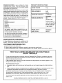
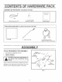
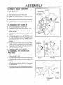
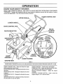

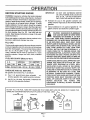


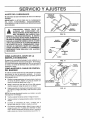
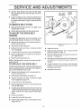
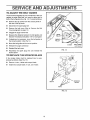
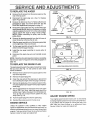
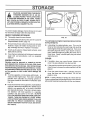
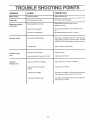
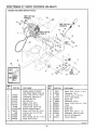
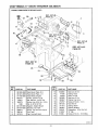
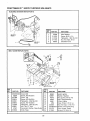
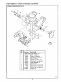
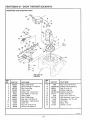
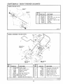


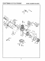
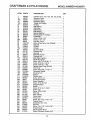
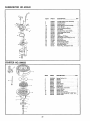
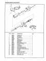
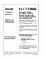


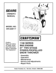
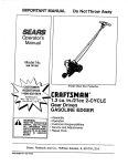
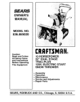

![CRRFTSMRN °] - at snowblowerguide.com](http://vs1.manualzilla.com/store/data/006202620_1-711fb90bb2c79d693479b4ac54c29ad0-150x150.png)