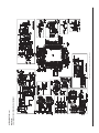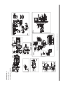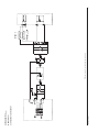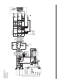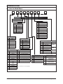
1
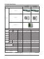
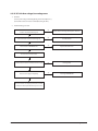
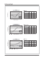
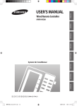
SYSTEM AIR CONDITIONER INDOOR UNIT Model : AC052FBMDEH/EU AC071FBMDEH/EU AC090FBMDEH/EU AC100FBMDEH/EU AIR CONDITIONER OUTDOOR UNIT AC052FCADEH/EU AC071FCADEH/EU AC090FCADEH/EU AC100FCADEH/EU AC100FCADGH/EU CONTENTS 1. Precautions 2. Product Specifications AC052FBMDEH/EU,AC071FBMDEH/EU, AC090FBMDEH/EU,AC100FBMDEH/EU 3. Disassembly and Reassembly 4. Troubleshooting 5. PCB Diagram AC071FCADEH/EU 6. Wiring Diagram 7. Schematic Diagram 8. Reference Sheet AC090FCADEH/EU AC100FCADEH/EU AC100FCADGH/EU AC052FCADEH/EU Refer to the service manual in the GSPN(see the rear cover) for the more information. Contents 11. Precautions ........................................................................................................................................ 1-1 1-1 Precautions for the Service .............................................................................................................. 1-1 1-2 Precautions related to static electricity and PL ............................................................................ 1-1 1-3 Precautions related to product safety ........................................................................................... 1-2 1-4 Other precautions.............................................................................................................................. 1-2 12. Product Specifications ............................................................................................................... 2-1 2-1 The Feature of Product ..................................................................................................................... 2-2 Product Specifications ...................................................................................................................... 2-1 2-2 2-3 Specifications of optional items...................................................................................................... 2-6 2-3-1 Accessories ............................................................................................................................... 2-6 13. Disassembly and Reassembly ............................................................................................... 3-1 3-1 Indoor Unit ......................................................................................................................................... 3-2 3-2 Outdoor Unit 3-7 ..................................................................................................................................... 14. Troubleshooting ............................................................................................................................ 4-1 4-1 Indoor Display Error and Check Method ..................................................................................... 4-1 4-1-1 Wired Remocon Error Display(COM2) ................................................................................ 4-2 4-2 Outdoor LED Error Display and Check Method ........................................................................... 4-3 4-3 Setting Option Setup Method ........................................................................................................ 4-4 Items to be checked first ................................................................................................................. 4-4 4-9 4-5 Fault Diagnosis by Symptom .......................................................................................................... 4-10 4-5-1 No Power(completely dead) - Initial diagnosis ................................................................. 4-10 4-5-2 The Outdoor unit Power Supply error ................................................................................ 4-11 4-5-3 The Outdoor unit Fan error .................................................................................................. 4-12 4-5-4 Total current trip error ........................................................................................................... 4-13 4-5-5 In case of heating at the cooling mode or cooling at the heating mode .................... 4-14 4-5-6 Outdoor temperature sensor error ..................................................................................... 4-16 .................................................................................. 4-17 4-5-8 Coil temperature sensor error .............................................................................................. 4-18 4-5-7 Discharge temperature sensor error 4-5-9 Fan error ................................................................................................................................... 4-19 4-5-10 DC-Link voltage sensor error ............................................................................................. 4-20 4-5-11 O.C.(Over Current) error ...................................................................................................... 4-21 4-5-12 Communication error .......................................................................................................... 4-22 4-5-13 Compressor start error ........................................................................................................ 4-23 4-5-14 Compressor lock error ......................................................................................................... 4-24 2 Samsung Electronics Contents 4-5-15 DC Link Over voltage/ Low voltage error ........................................................................ 4-25 4-6 PCB Inspection Method ................................................................................................................... 4-26 4-6-1 Pre-inspection Notices ........................................................................................................... 4-26 4-6-2 Inspection Procedure ............................................................................................................ 4-26 ............................................................................... 4-26 ........................................................................... 4-27 4-6-3 Indoor Detailed Inspection Procedure 4-6-4 Outdoor Detailed Inspection Procedure 4-7 Main Part Inspection Method ......................................................................................................... 4-28 1 15. PCB Diagram ..................................................................................................................................... 5-1 5-1 PCB Diagram ...................................................................................................................................... 5-1 .............................................................................................................................. 5-1 5-1-2 Outdoor Unit PCB ................................................................................................................... 5-4 5-1-1 Indoor Unit 16. Wiring Diagram .............................................................................................................................. 6-1 6-1 Indoor Unit ......................................................................................................................................... 6-1 ..................................................................................................................................... 6-2 6-2 Outdoor Unit 17. Schematic Diagram ...................................................................................................................... 7-1 7-1 Indoor Unit ......................................................................................................................................... 7-1 7-1-1 MAIN PCB ................................................................................................................................. 7-1 7-1-2 Outdoor Unit PCB ................................................................................................................... 7-3 1 8. Reference Sheet .............................................................................................................................. 8-1 8-1 Index for Model Name ...................................................................................................................... 8-1 8-2 Refrigerating Cycle Diagram............................................................................................................ 8-2 8-3 Pressure Graph ................................................................................................................................... 8-3 Samsung Electronics 3 1. Precautions 1-1 Precautions for the Service O Use the standard parts when replacing the electric parts. – Confirm the model name, rated voltage, rated current of the electric parts. O When repairing the equipment, connection of the harness parts must be firm and solid. – A loose connection may cause noise or other malfunction. O When assembling and disassembling the equipment while it is laid down, lay it on soft cloth. – Otherwise it may scratch the back of the exterior of the product. O Remove dust or dirt completely from the housing block, wiring block and service parts during repair. – This helps prevent the danger of fire caused by tracking or short circuit. O Fasten the valve caps of service valves and charging valves of outdoor unit as much as possible using adjustable wrenches. O Check the status of the components’ assembly after repair service. – The status must be the same as before the repair service. 1-2 Precautions related to static electricity and PL O The PCB power supply block is susceptible to static electricity. Therefore, care must be taken during repair or measuring while the power is on. – Wear insulation gloves for PCB repair or measuring. O Check whether the installation location is at least two meters away from other electronic products such as TV, video, or audio. – Otherwise, the video quality might be degraded or noise might be generated. O Do not let end users repair the products themselves. – Unauthorized disassembly might cause electric shock or fire. Samsung Electronics 1-1 1-3 Precautions related to product safety ODo not pull the power cord and do not touch the power plug or aux power switch with wet hands. – It might cause electric shock or fire. OA damaged power line or power plug must be replaced to prevent danger. ODo not bend the power cable with excessive force, and do not place a heavy weight on the case as it might damage the cable. – It might cause electric shock or fire. ODo not use multiple electric outlets. – This might cause electric shock or fire. OConnect the ground terminal when necessary. – You must connect the ground terminal if you determine that there is a danger of electric leakage due to moisture or water. OUnplug the power cable or turn off the auxiliary power switch for electric part replacement and repair service. – Otherwise it might cause electric shock. OInstruct end users to separate the batteries from the remote controllers and store them separately when the product is not used for long time. – Otherwise leakage from the dry cell may cause problems with the remote controller. 1-4 Other precautions O The pipes should have no leaks during installation, and the compressor must be stopped before removing connecting pipes for pump down work. Operating the compressor while the service valve is open and coolant pipe is not properly connected may cause explosion or injury due to abnormal high pressure created inside the coolant cycle as the air can be absorbed through the pipe. O Pump Down work procedure (When uninstalling the product) – Turn on the air conditioner, select cooling operation, and run the compressor for more than three minutes. – Release the high pressure and low pressure valve caps. – Close the high pressure valve completely using an L-wrench – After about two minutes, close the low pressure valve completely. – Stop running the air conditioner. – Separate the connecting pipe. 1-2 Samsung Electronics 2. Product Specifications 2-1 The Feature of Product QBuilt-in Cassette Type After installed, the air conditioner can be harmonized with a room interior. QHigh Performance & Energy Saving With the advanced BLDC inverter technology, it makes a room cool with highly energy saving and arises the efficiency of air conditioner. QLong Piping(Length & Height) It can give the benefit to the installers and aries the reliability of the air conditioner. QLong Ambient Operation(In Low Temperature) It can arise the reliability and the capacity of the air conditioner, especially operated in low temperature. QEco-friendly Product(Lead-Free, RoHS, WEEE) Samsung Electronics 2-1 2-2 Product Specifications AC052FBMDEH/EU AC052FCADEH/EU ITEM AC071FBMDEH/EU AC071FCADEH/EU Indoor Unit Outdoor Unit IMAGE Remote Controller Power Specifications Indoor 1Φ, 220~240V,50Hz WxHxD mm 900x260x480 1150x480x260 WxHxD Size Outdoor mm 750x548x285 880x310x798 Indoor Unit kg 28.0 31.5 Outdoor Unit kg 38.5 55.0 Weight Cooling(STD) W 5000 7100 Heating(STD) W 6000 8000 Cooling(STD) W 1560 2210 Heating(STD) W 1660 2220 Cooling(STD) A 7.5 10.5 Heating(STD) A 7.8 10.5 dBa 60 65 dBa 64 66 g 1400 1800 Capacity Power Consumption Operation current Sound Power (Cooling/ Heating) Indoor Outdoor In case of strongest air blow In case of strongest air blow Refrigerant (R410A) Liquid mm 1/4" 1/4" Gas mm 1/2" 5/8" g/m 10 25 Connecting Pipe Additional Refrigernat (R410A) Standard m 5 5 Extension length(Total) m 30 50 Extension length(Elevation) m 20 30 Product Option 011014-19626E-27343C-370010 011017-1563A2-274750-370010 Installation Option 020000-100000-200000-300000 020000-100000-200000-300000 Option Code 2-2 Samsung Electronics Product Specifications (cont.) AC090FBMDEH/EU AC090FCADEH/EU ITEM AC100FBMDEH/EU AC100FCADEH/EU AC100FBMDEH/EU AC100FCADGH/EU Indoor Unit Outdoor Unit IMAGE Remote Controller Power Specifications 1Φ, 220~240V,50Hz 3Φ,380~415V,50Hz Indoor WxHxD mm 1150x480x320 Outdoor WxHxD mm 940x330x998 Indoor Unit kg 35.0 Outdoor Unit kg 72.0 Size Weight Cooling(STD) W 9000 10000 Heating(STD) W 10000 11200 Cooling(STD) W 2800 3215 Heating(STD) W 2770 Cooling(STD) A 13.0 15.2 5.4 Heating(STD) A 12.5 13.5 5.2 A 65 65 65 A 67 68 68 g 3000 3000 3100 mm 3/8" 3/8" 3/8" Capacity Power Consumption Operation current Sound Power(Cooling/ Heating) Indoor Outdoor In case of strongest air blow In case of strongest air blow Refrigerant (R410A) Liquid 3100 Connecting Pipe mm 5/8" 5/8" 5/8" Additional Refrigernat (R410A) g/m 50 50 50 Standard m 5 5 5 Extension length(Total) m 50 50 50 Extension length(Elevation) m 30 30 30 Gas Product Option Option Code Installation Option Samsung Electronics 011034-15617C275A64-350000 020000-100000200000-300000 011034-15617C-276470-370000 020000-100000-200000-300000 2-3 2-3 Specifications of optional items 2-3-1 Accessories Item Descriptions Code-No. Q'TY Wired remote controller DB97-15070D 1 Owner's Manual DB98-32657A 1 Installation Manual DB98-03356A 1 Insulation-Cover Band DB62-04318S 1 Remark TIONS OWNER'S INSTRUC INSTRUCCIONES MANUAL DE PER L'USO ISTRUZIONIINSTRU‚Í ES MANUAL DE ATION MANUEL D'UTILISEISUNG GEBRAUCHSANW Air ConditionerSplit Splut-type Room domĿstico sistema ad unitˆ Separate Aire acondicionado d'aria per ambienti Split Condizionatorede ar condicionado tipo Aparelho type sĿparĿ Climatiseur de e Geteilte raumklimaanlag TIONS OWNER'S INSTRUC INSTRUCCIONES MANUAL DE PER L'USO ISTRUZIONIINSTRU‚Í ES MANUAL DE ATION MANUEL D'UTILISEISUNG GEBRAUCHSANW Air ConditionerSplit Splut-type Room domĿstico sistema ad unitˆ Separate Aire acondicionado d'aria per ambienti Split Condizionatorede ar condicionado tipo Aparelho type sĿparĿ Climatiseur de e Geteilte raumklimaanlag Indoor Unit Insulation-Drain Hose DB62-11028A 1 Insulation-Hose D DB62-11028E 1 Insulation-Tube Out DB62-11028F 1 Cable-tie DB65-10088C 8 Grommet-Hanger DB63-00237A 8 Ass'y Drain Hose Joint DB94-03287A 1 RUBBER LEG DB73-20134A 4 Outdoor unit DB67-20011A 1 AC071FCADEH DB67-00477A 1 AC052FCADEH DB67-00806A 1 AC090FCADEH AC100FCADEH AC100FCADGH DB98-32793A 1 AC090FCADEH AC100FACADEH AC100FACADGH DB68-03464A 1 AC052FCADEH AC071FCADEH DRAIN PLUG TIONS OWNER'S INSTRUC INSTRUCCIONES MANUAL DE PER L'USO ISTRUZIONIINSTRU‚Í ES MANUAL DE ATION MANUEL D'UTILISEISUNG GEBRAUCHSANW Air ConditionerSplit Splut-type Room domĿstico sistema ad unitˆ Separate Aire acondicionado d'aria per ambienti Split Condizionatorede ar condicionado tipo Aparelho type sĿparĿ Climatiseur de e Geteilte raumklimaanlag Installation manual 2-4 Samsung Electronics Accessories (cont.) ■ Receiver & display unit & Wire kit Item Descriptions Code-No. Q'TY Receiver & display unit DB93-00449A (MRK-B00) 1 STS 2S-2x10 Tapped Screw - 4 2S-4x12 Tapped Screw - 2 User’s manual DB98-05160A 1 Installation manual DB98-05186A 1 Wire kit DB39-00223A (MRW-10A) 1 Receiver & display unit DB93-01066A (MRK-A00) 1 M4x12 Tapped Screw - 7 Cable-tie - 2 Remark Concealed type Standard type Samsung Electronics User’s manual DB98-04184A 1 Installation manual DB98-04189A 1 Wire kit DB39-00223A (MRW-10A) 1 2-5 Accessories (cont.) ■ Wireless remote controller Item 2-6 Descriptions Code-No. Q'TY Wired remote controller DB97-14333C (MWR-WH02) 1 Cable tie DB65-10088B 2 Cable clamp DB65-10074E 5 M4×16 Tapped Screw 6002-000474 7 Indoor unit power drawing cable DB39-00221A 1 Communication cable of thewired remote controller DB39-00933A 1 Wire joint DB39-90020A 1 User’s manual DB98-25179A 1 Installation manual DB98-25180A 1 Remark Optional Samsung Electronics Accessories (cont.) ■ Centralized controller Item Descriptions Code-No. Q'TY Centralized controller DB93-03425C (MCM-A202) 1 Cable tie DB65-10088B 2 Cable clamp DB65-10074E 5 Remark Optional Samsung Electronics M4x16 Tapped Screw 6002-000474 7 User’s manual DB98-12721A 1 Installation manual DB98-25773A 1 2-7 Accessories (cont.) ■ Function controller Item Descriptions Code-No. Q'TY Function controller DB97-01077A (MCM-A100) 1 Cable tie DB65-10088B 2 Cable clamp DB65-10074E 6 Remark Optional M4x16 Tapped Screw 6002-000474 7 User’s manual DB98-27317A 1 Installation manual DB98-27315A 1 Descriptions Code-No. Q'TY Transmitter DB97-00647P (MIM-B04A) 1 Transmitter power cable DB39-00378D 1 Transmitter communication cable DB39-00253D 1 ■ Transmitter Item 2-8 Remark Optional Samsung Electronics Accessories (cont.) ■ DMS(Date Management Server) Item Samsung Electronics Descriptions Code-No. Q'TY DMS DB93-03709B (MIM-D00) 1 Cable tie DB65-10088B 2 Cable clamp DB65-10074D 2 M4x16 Tapped Screw 6002-000474 5 Bottom hook DB73-00320A 4 User’s manual DB98-27317A 1 Installation manual DB98-27315A 1 Remark Optional 2-9 3. Disassembly and Reassembly Q Necessary Tools Item Remarks +SCREW DRIVER Adjustable Wrench (8mm, 10mm, 13mm) 3-1 Samsung Electronics 3-1 Indoor unit No Parts 1 Blower & Motor Procedure Remark 1) After disassembling 16 places indicating screws, detach Ass'y Cabi Bottom Blower. (Use +Screw Driver) 2) Detach the Motor Fan connector from the BLDC PCB. 3) After disassembling 2 places indicating screws, detach the 2 Fan Case. (Use +Screw Driver) Samsung Electronics 3-2 No Parts Procedure Remark 4) After disassembling 2 places indicating screws, detach Fan Motor and Blower from the set. 2 Control In 1) After disassembling 3 Indicating screw, detach the Cover control. (Use +Screw Driver) 2) Detach the Motor-Fan and Sensor Connector from the PCB. 3-3 Samsung Electronics No Parts Procedure Remark 3) Disassemble 4 indicating screws and detach Control In from the set. 3 Drain Pan Work is possible when Disassembling the Ass'y Cabi Bottom Blower. 1) Disassemble 7 indicating screws and detach Ass'y Cabi Bottom Drain.. Samsung Electronics 3-4 No Parts Procedure Remark 1) Disassemble 4 indicating screws and detach the Drain Pan. (Use +Screw Driver) (2 screws each at left and right side). 4 Evap Work is possible when Disassembling the Ass'y Drain Pan. 1) Disassemble 5 indicating screws to detach Cover Pipe. (Use +Screw Driver) 3-5 Samsung Electronics No Parts Procedure Remark 2) Disassemble Sensor on the Evap. 3) Disassemble 4 indicating screws which are in the near of Hanger Plate to detach the Evap. (Use +Screw Driver) (2 screws each at left and right side) It needs 2 peoples.. Samsung Electronics 3-6 3-2 Outdoor Unit Q AC052FCADEH/EU No Parts Procedure 1 common work 1) loosen 1 pcs screw of cover control,and detach it. Remark 2) loosen 5 pcs screws on both right and left cabniet side edges and to detach the cover-top 3) Loosen 7 screwsfixed to disassemble cabi-front , and detach it. 3-7 Samsung Electronics No Parts common work Procedure Remark 4) loosen 7 screws to disassemble the cabiright ,and detach it. 5) loosen 2 screws to disassemble steel-bar. 6) loosen 3 screws to disassemble cabi-left. Samsung Electronics 3-8 No Parts Procedure 2 fan&motor 1) loosen 1 screw as indication and detached the fan. Remark 2) loosen 4 pcs motor screws and disconnect the wire betwwen assy control out and motor. 3) loosen 2 pcs bracket-motor screw and detach it. 3-9 Samsung Electronics No Parts 3 assy control out 1) lossen fixing 1 screw from cover -control 2) detach several connections from assy control out, take out assy control out. 4 Heat exchanger 1) Release the refrigerant at first 2) Looosen fixing screw on both side. 3) disaessembly the pipes in both inlet and outlet with welding torch. 4) detach the heat exchanger. Samsung Electronics Procedure Remark 3-10 No Parts 5 compressor Procedure Remark 1) disconnect the compressor lead wire . 2)disassembly the felt comp sound. loosen the 3 bolts at the bottom of 3-11 Samsung Electronics Q AC071FCADEH/EU No Parts Procedure 1 Common Work 1) Loosen 1 fixing screw of the Cover-Control and detach the Cover Control. Remark 2) Loosen each 7 fixing screws and detach the Cabinet Upper. Samsung Electronics 3-12 No Parts Procedure Remark 3) Loosen 2 screws fixed to assemble Control Box with Cabinet-Side RH. 4) Loosen fixing screws and detach the Cabinet-Side RH. 5) Loosen 2 screws fixed on the Guide Condenser. 3-13 Samsung Electronics No Parts Procedure Remark 6) Loosen fixing screws of the Cabinet Front. Samsung Electronics 3-14 No Parts 2 Fan & Motor Procedure Remark 1) Detach the Nut Flange like the picture on the right side. (Turn counter clockwise because the screw is right-handed.) 2) Detach the Fan Propeller. 3) Loosen 4 fixing screws to detach the Motor. 4) Disconnect the wire between ASS'Y Control Out and Motor. 5) Loosen 2 fixing bolts and detach the Bracket Motor. 3-15 Samsung Electronics No Parts Procedure 3 ASS'Y Control Out 1) Detach several connectors from the ASS'Y Control Out. 2) Detach several connectors from the PCB of ASS'Y Control Out. 3) Pull up the ASS'Y Control Out. 4 Heat Exchanger 1) Release the refrigerant at first. 2) Loosen fixing screw on both sides. 3) Disassemble the pipes in both inlet and outlet with welding torch. 4) Detach the Heat Exchanger. Remark 5) Loosen 4 bolts fixed to assemble Valve Service with Bracket Valve like the picture on the right side. Samsung Electronics 3-16 No Parts 5 Compressor Procedure Remark 1) Loosen the fixing nut and detach the Compressor Lead Wire. 2) Disassemble the Felt Compressor Sound. 3) Loosen the 3 bolts at the bottom of Compressor like the picture on the right side. 3-17 Samsung Electronics NAC090FCADEH/EU AC100FCADEH/EU AC100FCADGH/EU No Parts 1 Cabi Front RH Procedure Remark You must turn off the Power before disassembly. 1) Unscrew and remove two mounting screw in the Cabinet Front RH. (Use +Screw Driver) 2 Cabi Top 3 Cabi Install Front Samsung Electronics 1) Unscrew and remove 9 screws on each side of the Cabinet-Top. (Use +Screw Driver) 1) Unscrew and remove 1 screw in the Cabinet-Install Front. (Use +Screw Driver) 3-18 No Parts 4 Guard Cond Procedure Remark 1) Pull the sensor from Guard Cond. 2) Unscrew and remove 4 screws in the Guard Cond. (Use +Screw Driver) 5 Cabi Back RH 1) Pull the sensor from Cabi Back RH. 2) Unscrew and remove 4 screws on each side of the Cabinet Back RH. (Use +Screw Driver) 3-19 Samsung Electronics No Parts 6 Cabi Install Back 7 Cabi Front LF Samsung Electronics Procedure Remark 1) Unscrew and remove 1 screw in the Cabinet-Install Back. (Use +Screw Driver) 1) Unscrew and remove 10 screws in the Cabinet-Front LF. (Use +Screw Driver) 3-20 No Parts 8 Fan 3-21 Procedure Remark 1) Turn 2 mounting nuts as shown in the picture and remove it. (Use Adjustable Wrench) Samsung Electronics No Parts Procedure 9 Motor 1) Separate the Fan Propeller. 2) Unscrew and remove the 4 Motor mounting screws. (Use +Screw Driver) Remark 3) Disconnect the Motor wire From Ass'y Control Out. 10 Bracket Motor Samsung Electronics 1) Unscrew and remove 2 mounting screws in Bracket Motor. (Use +Screw Driver) 3-22 No Parts 11 Control Out Procedure Remark 1) Disconnect 4 Connecters From Ass'y Control Out. 2) Unscrew and remove 1 mounting screw in Control Out. (Use +Screw Driver) 3) Separate Ass'y Control Out. 3-23 Samsung Electronics No Parts 12 Ass'y 4way Valve Procedure Remark 1) Purge the Coolant first. 2) Unscrew and remove 2mounting screws in muffler. 3) Unscrew and remove 2 mounting screws in Service Valve. (Use +Screw Driver) 4) Separate the pipe from the Entrance/Exit using a welder. When removing the compressor, Heat Exchanger, and Pipe, purge the Coolant inside the Compressor completely and remove the pipe with a welding flame. Samsung Electronics 3-24 No Parts 13 Ass;y EEV Valve Procedure Remark 1) Unscrew and remove 2 mounting screws in Service Valve. (Use +Screw Driver) 2) Separate the pipe from the Entrance/Exit using a welder. 14 Compressor 1) Unscrew and remove 1 mounting nut in Cover Terminal. (Use Adjustable Wrench) 2) Separate the Compressor Felt Sound. 3-25 Samsung Electronics No Parts Procedure Remark 3) As shown in the picture, unscrew and remove 3 mounting screws from the bottom. (Use Adjustable Wrench) 15 Cond Out 1) Unscrew and remove 3 screws on each side of the Assy Cond Out. (Use +Screw Driver) 2) Separate the Compressor Felt Sound. Samsung Electronics 3-26 4. Troubleshooting 4-1 Indoor Display Error and Check Method ■ Error detection and reoperation ▶ If error occurs during the operation, badness is indicated by LED flickering and all operation is stopped except LED. ▶ When reoperating by remote control and switch determine the error mode after normal operation. ■ Indoor unit LED lamp display at error detecting LED Iamp display Error type Operation Defrost Timer Air flow Filter Power reset ◑ X X X X Error of temperature sensor in the indoor unit(Open/Short) X X ◑ X X Error of heat exchanger sensor in the indoor unit ◑ X ◑ X X Error of the outdoor temperature sensorError of the condensor temperature sensor Error of the discharge temperature sensorPower reset ◑ X X ◑ X 1. No communication for 2 minutes between indoor units (Communication error for more than 2 minutes) 2. Indoor unit receiving the communication error from outdoor unit 3. Outdoor unit tracking 3 minutes error 4. When sending the communication error from the outdoor unit, the mismatching of the communication numbers and installed numbers after completion of tracking4. (Communication error for more than 2 minutes) X X ◑ ◑ X 1. Error of electronic expansion valve close 2. Error of electronic expansion valve open 3. 2'nd detection of high temperature cond 4. 2'nd detection of high temperature discharge 5. Error of reverse phase 6. Compressor down due to 6'th detection of freezing X X ◑ ◑ ◑ Detection of the float switch X X X ◑ ◑ Error of setting option switches for optional accessories X X ◑ X ◑ EEPROM option error ◑ ◑ ◑ ◑ ◑ Remarks ● : ON, ◑ : Flickering, X : OFF ※ If you turn off the air conditioner when the LED is flickering, the LED is also turned off. 4-1 Samsung Electronics 4-1-1 Wired Remocon Error Display(COM2) •If an error occurs, is displayed on the wired remote controller. If you would like to see an error code, press the Test button. Display Explanation Remark Indoor unit Communication Error Indoor/Outdoor unit Communication Time Out Error 60 Packet Over data Indoor unit is not connected Communication Error Communication Error between Outdoor Main and Inverter Micom (Occurred after 1 minute detection in Main and Inverter) Indoor Temp. Sensor(Open/Short Error) Indoor Unit Eva in Sensor(Open/Short Error) Indoor Sensor Error Indoor Unit Eva in Sensor Separation Outdoor Temp. Sensor Error(Open/Short Error) COND Temp. Sensor Error(Open/Short Error) Outdoor Sensor Error Inverter Compressor Discharge Temp. sensor Error(Open/Short Error) Power cable miss connection error Indoor Float Switch 2nd Detection Outdoor unit - indoor unit communication wire miss connection (Connected to Power terminal) Outdoor unit refrigerant Full leakage(Gas leak) Self Diagnosys Error Outdoor Fan 1 Error Outdoor Fan 2 Error Discharge over temperature [Inverter] Compressor starting error Primary Current Over Trip error [Inverter]IPM Over Current(O.C) Outdoor UnitProtetion Control Error [Inverter] Compressor Rotation error [Inverter] Current Sensor error [Inverter] DC LINK Sensor error [Inverter] EEPROM Read/Write Error [Inverter] Heatsink temperature over Error Outdoor UnitProtetion Control Error Outdoor unit Capacity Setup option error Communication error between Indoor unit and wired remote control Communication error between Master and Slave wired remote control Wired remote control error COM1/COM2 Cross-installed error Error of setting option for wired remote control COM2 Samsung Electronics 4-2 4-2 Outdoor LED Error Display and Check Method No. LED Display Explanation Error Code Yellow Green Red 1 | | | Power off/ VDD NG 2 | | IPM Over Current(O.C) | | z | z z 4 | | Compressor Starting error 5 | z Normal Operation 6 | z | Compressor Lock error 7 | z DC-Link voltage under/over error 8 | Outdoor temperature sensor error 9 | z Discharge over temperature 10 | Discharge temperature sensor error 11 z Current sensor error 12 z | Compressor Limit error 13 z Coil temperature sensor error 14 z z 1min. Time out Communication 15 z | | Fan error 16 z | OTP error 17 z | z Compressor rotation error 18 z | Operation condition secession 19 z DC-Link voltage sensor error 20 z z I_Trip error 21 z z | GAS Leak error 22 z z Power Cable miss connection 23 z z z Power ON reset(1sec) 24 | | Capacity miss match 25 | Test Operation at Cooling Mode - 26 Test Operation at Heating Mode - 3 - Abnormal Serial communication/Power Cable Miss Connection - - | Off 4-3 Blink z On Samsung Electronics 4-3 Setting Option Setup Method Setting an indoor unit option code Model Option code AC052FBMDEH 011014-19626E-27343C-370010 Model AC100FBMDEH AC052FCADEH AC100FCADEH AC071FBMDEH AC100FBMDEH AC071FCADEH AC090FBMDEH AC090FCADEH 011017-1563A2-274750-370010 Option code 011034-15617C-276470-370000 AC100FCADGH 011034-15617C-275A64-350000 In order to set the indoor unit option code using the wired remote controller, hold down the and buttons at the same time for 5 seconds. 1 The menu will display . Press the button to enter the indoor unit option code mode. tThe first digit represents the page number and the remaining five digits are option codes. Page No. 2 Press the button to change the page. You can change the page from 0 to 3. 3 Press the buttons and the option code in order. button to set the tThe option code which is currently setting will flicker. Option code 4 Press the button to save the changed setting. You will move to the menu selection display. t Press the button anytime during setup to exit without setting. tOption code will not be applied if you don’t press the button. tSetting indoor unit option code is only possible in Master wired remote controller. You can only check the indoor unit option code in Slave wired remote controller. tSetting indoor unit option code is possible when one indoor unit is connected. If more than 2 indoor units are connected, you can only check the Master indoor unit option code. Samsung Electronics 4-4 Set the indoor unit address and installation option with remote controller option. Set the each option separately since you cannot set the ADDRESS setting and indoor unit installation setting option at the same time.You need to set twice when setting indoor unit address and installation option. Setting an indoor unit address In order to check and set the indoor unit Main/Group Address using the wired remote controller, hold down the 1 2 and buttons at the same time for 5 seconds. The menu will display . Press the button and the menu will display . Press the button. The main address (decimal notation) and group address (hexadecimal notation) of currently set indoor unit will be displayed. Menu No. 3 Press the buttons and the indoor unit Main/Group Address. 4 Press the button to set the button. Wired remote controller sends data to an indoor unit. 5 Checking the Indoor unit Indoor unit RMC address main address Setting the Indoor unit main address Press the button to exit. You will move to the menu selection display. tPress the button anytime during setup to exit without setting. tSetting main/group address of an indoor unit is available only with a master wired remote controller. 4-5 Samsung Electronics Setting an indoor unit installation option In order to check and set the indoor unit DIP option code using the wired remote controller, hold down the and buttons at the same time for 5 seconds. 1 The menu will display . button until Press the is displayed. 2 Press the button. The current DIP option code set in an indoor unit will be displayed. Page number DIP OPTION CODE 3 Press button and change the page number. The total option codes are 24digits.you can set six digits at a time and it is distinguished by page number(0,1,2,3). SGE1 SGE2 SGE3 0 2 RESERVED SEG7 1 SEG13 SEG8 Drain pump SEG14 SEG9 HOT COIL SEG15 SGE4 Exterior temperature sensor SEG10 RESERVED SEG16 2 External control External control output RESERVED Buzzer SEG19 SEG20 Individual control of a remote controller SEG21 - RESERVED - 3 Samsung Electronics SGE5 SGE6 Central control RESERVED SEG11 RESERVED SEG17 - SEG12 Master / Slave SEG18 Number of hours using filter - - - 4-6 Option No. : 02XXXX-1XXXXX-2XXXXX-3XXXXX Option SEG1 Explanation Indication and Details PAGE SEG2 SEG4 Use of external temperature sensor MODE Indication Details Indication Details 0 SEG3 RESERVED Indication Details Indication 0 1 2 Option Explanation SEG7 SEG8 SEG9 PAGE Use of drain pump HOT COIL Indication Details Indication Details Indication Details 0 Disuse 0 Disuse Indication 1 Use 1 Use and Details 1 Use + 2 3minute delay Option SEG13 SEG14 SEG15 Use of external Setting the output of Explanation PAGE control external control Indication Details Indication Details Indication Details Thermo Disuse 0 0 on Indication ON/OFF and Details 2 1 Control Operation 1 on OFF 2 Control Option SEG19 SEG20 SEG21 Individual control Explanation PAGE of a remote controller Indication Details Indication Details RESERVED 0 or 1 Indoor 1 Indication Indoor 2 2 and Details 3 Indoor 3 3 Indoor 4 4 4 5 Press the buttons and the Indoor unit DIP option code. Press the SEG5 Disuse Use SEG10 RESERVED SEG6 Use of central control 0 1 RESERVED Details Disuse Use SEG11 RESERVED SEG12 Master / Slave Indication Details 0 slave 1 master - SEG16 SEG17 Buzzer control Indication RESERVED Details Use of buzzer 0 Non use of buzzer 1 - SEG18 Number of hours using filter Indication Details 2 1000 Hour 6 2000 Hour - - - - - - - - - - - - - - - - button to set the button. Wired remote controller sends data to an indoor unit. 6 Press the button to exit. You will move to the menu selection display. tPress the button anytime during setup to exit without setting. tSetting an indoor unit DIP option code is available only with a master wired remote controller. tSetting an indoor unit DIP option code is available when there is one on one connection between a wired remote controller and an indoor unit. tIndoor unit DIP option code will not be applied if you don’t press the button. 4-7 Samsung Electronics Setting an indoor unit option code Model SEG1 SEG2 SEG3 SEG4 SEG5 0 1 1 0 1 AC052FBMDEH 0 1 1 0 1 AC052FCADEH 0 1 1 0 1 AC071FBMDEH 0 1 1 0 1 AC071FCADEH 0 1 1 0 3 AC090FBMDEH 0 1 1 0 3 AC090FCADEH 0 1 1 0 3 AC100FBMDEH 0 1 1 0 3 AC100FCADEH 0 1 1 0 3 AC100FBMDEH 0 1 1 0 3 AC100FCADGH Model SEG13 SEG14 SEG15 SEG16 SEG17 2 7 3 4 3 AC052FBMDEH 2 7 3 4 3 AC052FCADEH 2 7 4 7 5 AC071FBMDEH 2 7 4 7 5 AC071FCADEH 2 7 5 A 6 AC090FBMDEH 2 7 5 A 6 AC090FCADEH 2 7 6 4 7 AC100FBMDEH 2 7 6 4 7 AC100FCADEH 2 7 6 4 7 AC100FBMDEH 2 7 6 4 7 AC100FCADGH Samsung Electronics SEG6 SEG7 SEG8 SEG9 SEG10 SEG11 SEG12 4 4 7 7 4 4 4 4 4 4 1 1 1 1 1 1 1 1 1 1 9 9 5 5 5 5 2 2 3 3 1 1 1 1 1 1 6 6 A A 7 7 E E C C SEG18 SEG19 5 5 5 5 SEG20 6 6 6 6 6 6 6 6 6 6 SEG21 SEG22 7 7 7 7 SEG23 C C C C SEG24 C C 0 0 4 4 0 0 0 0 3 3 3 3 3 3 3 3 3 3 7 7 0 0 7 7 0 0 5 5 7 7 7 7 0 0 0 0 0 0 0 0 0 0 0 0 0 0 0 0 1 1 1 1 0 0 0 0 0 0 0 0 0 0 0 0 0 0 0 0 2 2 4-8 4-4 Iterms to be checked first 1. The input voltage should be rating voltage ±10% range. The air conditioner may not operate properly if the voltage is out of this range. 2. Is the link cable linking the indoor unit and the outdoor unit linked properly? The indoor unit and the outdoor unit shall be linked by 4 cables. Check the terminals if the indoor unit and outdoor unit are properly linked by the same number of cables. Otherwise the air conditioner may not operate properly. 3. When a problem occurs due to the contents illustrated in the table below it is a symptom not related to the malfunction of the air conditioner. 4-9 No Operation of air conditioner Explanation 1 In a COOL operation mode, the compressor does not operate at a room temperature higher than the setting temperature that the INDOOR FAN should operate. [In case of heat pump model] In a HEAT operation mode, the compressor does not operate at a room temperature lower than the setting temperature that indoor fan should operate. In happens after a delay of 3 minutes when the compressor is reoperated. The same phenomenon occurs when a power is on. As a phenomenon that the compressor is reoperated after a delay of 3 minutes, the indoor fan is adjusted automatically with reference to a temperature of the air blew. 2 Compressor stops operation intermittently in DRY( ) mode. Compressor operation is controlled automatically in DRY mode depending on the room temperature and humidity. 3 [In case of heat pump model] Compressor of the outdoor unit is operating although it is turned off in a HEAT mode. When the unit is turned off while de-ice is activated, the compressor continues operation for up to 12 minutes(maximum) until the deice is completed. 4 [In case of heat pump model] The compressor and indoor fan stop intermittently in HEAT mode. The compressor and indoor fan stop intermittently if room temperature exceeds a setting temperature in order to protect the compressor from overheated air in a HEAT mode. 5 [In case of heat pump model] Indoor fan and outdoor fan stop operation intermittently in a HEAT mode. The compressor operates in a reverse cycle to remove exterior ice in a HEAT mode, and indoor fan and outdoor fan do not operate intermittently for within 20% of the total heater operation. Samsung Electronics 4-5 Fault Diagnosis by Symptom 4-5-1 No Power(completely dead) - Initial diagnosis 1. Checklist : 1) Is Power source voltage normal? 2) Is AC power linked correctly? ( miss-wiring, wire detaching etc. ) 3) Is any LED on the MAIN PCB of Outdoor unit lit? 4) Is terminal voltage for indoor unit normal? (230Vac nominal) 5) Is Wired remote controller installed correctly? 2. Troubleshooting procedure Turn off the breaker and turn it on after 30 seconds Check outdoor unit terminal block voltage on each N-R,N-S,N-T (230Vac nominal) No Check AC power source. Reconnect wires correctly. Yes Check outdoor unit terminal block voltage on L-N for indoor unit (230Vac nominal) No Check Inner wiring of outdoor unit. Yes Check indoor unit terminal block voltage on L-N (230Vac nominal) No Check cable and connection of wire between indoor and outdoor unit. No Check Indoor control PCB, Transformer, and FUSE on PCB and replace one which is broken. No Check cable and connection of wire between remote controller and indoor unit. Yes Check indoor unit terminal block voltage on V1-V2 (12Vdc nominal) Yes Check DC power voltage of remote controller(V1,V2) Yes Press the On/Off button on the wired remote controller to operate the air conditioner No Replace wired remote controller. Yes Check DIP SW in the wired remote controller No Set DIP SW correctly. Yes Is there any error display on the wired remote controller No Check each item according to error code list. No Check the setting temperature Samsung Electronics 4-10 4-5-2 The Outdoor unit Power Supply error 1. Checklist : 1) Are the input power voltage and power connection correct? 2) Is there any Fuse Short of the indoor or outdoor unit? 3) Is any LED lit on both MAIN PCB and INVERTER PCB? 4) Are Reactor wires of the outdoor unit connected correctly? 2. Troubleshooting procedure Check LEDs on both MAIN PCB and INVERTER PCB after1 minutesfrom power on Is voltage on N-T of terminal block over 300V? Yes Check and correct the power cable wiring No MAIN PCB ALL OFF Error 202 display (Table No. 14) INVERTER PCB ALL OFF Are wire and socket connected correctly? Power line N and T wire(Terminal block reactor - EMI PCB), CN9(EMI PCB), CN80(MAIN PCB) No Check and correct the wire or socket connection Yes Check Fuses listed blow FUSE3(EMI PCB), FUSE(MAIN PCB) Yes Correct the cable wiringbetween indoor and outdoor Is there miss connection of power andcommunication wire betweenindoor and outdoor? Normal No Error 425 display (Table No. 22) ALL OFF Is there any power wire detachingespecially phase R and S? Are wire and socket connected correctly? CN31(MAIN PCB), CN10(INVERTER PCB) Error 203 display (Table No. 3) ALL OFF Check F1,F2 communication line wiring. CN50(MAIN PCB) Yes Check and correct the power cable wiring No Check Fuses listed blow FUSE1(EMI PCB), FUSE2(EMI PCB) No Check and correct the wiring Yes Is the FUSE on INVERTER PCB blown? Yes Replace the FUSE No Error 466 display (Table No. 7) Error 466 display (Table No. 7) Is R100 on INVERTER PCB open?(200ohm moninal) Yes No Also check each BLDC FAN motoshort or not, by resistance betweenpin #1 and #3 Check INVERTER PCB Error 469 display (Table No. 19) Error 469 display (Table No. 19) Are wire and socket connected correctly? CN05,06,07 TAB terminal(EMI PCB), CN20(INVERTER PCB) No Yes 4-11 Replace INVERTER PCB Check and correct the wiring Check the M/C Samsung Electronics 4-5-3 The Outdoor unit Fan error 1. Checklist : 1) Are the input power voltage and power connection correct? 2) Is the motor wire connected to the outdoor PCB correctly? 3) Is there no obstacle at the surrounding of motor and propeller? 4) Does the driver in the motor case broken? 2. Troubleshooting procedure Is the connection of FAN housing certainly to PCB socket?(CN40, CN41) No Check AC power source. Reconnect wires correctly Yes Take off each Fan motor housing after 1 minutes from turning off the power Is each resistance of FAN cable housing pin #1-#3 over 1Mohm, pin #4-#3, #5-#3 and #6-#3 over 1Kohm on each FAN motor? No # TEST operation # press K900 button on the MAIN PCB after power on. - once : cooling mode - twice in a second : heating mode Yes Mount each Fan housing to PCB socket and turn on the power Is the Pin voltage #1 - #3 of CN40 and 41over 250V? Exchange the FAN motor because of driver inside of the motor case broken No Follow the check procedure of outdoor unit power supply error check Yes Is the Pin voltage #5 - #3 of CN40 and 41 15V? No Exchange INVERTER PCB Yes Is the Pin voltage #5 - #3 of CN40 and 41within 1-6V during the operation? No Exchange INVERTER PCB Yes Is the Fan in rotation during TEST operation in cooling mode No Exchange the FAN motor not in rotation Yes Is the Pin voltage #6 - #3 of CN40 and 41changed high(4-5V) and low(0-1V) in case ofmaking manual rotation slowly? Yes Exchange INVERTER PCB No Is the Pin voltage #7 - #3 of CN40 and 41 low(0-1V) in normal rotation? No Exchange the FAN motor Yes Exchange the FAN motor Samsung Electronics 4-12 4-5-4 Total current trip error 1. Checklist : 1) Is the input power voltage proper? 2) Is the refrigerant charged properly? 3) Does the compressor rotate normally?(Reverse rotation, Locking etc.) 4) Does the outdoor fan operate normally?(Fan propeller loss, Motor error ect.) 5) Is the installation condition of outdoor unit good?(Piping, Space etc.) 6) Is there no ventilation obstruction at the surrounding of outdoor unit?(Outdoor unit cover, Fan front obstruction etc.) 7) Is there no ventilation obstruction at the surrounding of indoor unit?(Overload condition in heating mode) 2. Troubleshooting procedure Is the installation of outdoor unit good? No Reinstall and remove the obstruction Yes Is the installation of indoor unit good? No Reinstall and remove the obstruction No Exchange the compressor No Open valve screw to the end No Check AC power source Yes Does the compressor rotate normally? Yes Are the service valves full opened? Yes Is AC power voltage normal during thecompressor in operation? Yes Exchange INVERTER PCB 4-13 Samsung Electronics 4-5-5 In case of heating at the cooling mode or cooling at the heating mode 1. Troubleshooting procedure No Is the Thermo off? Change the setting temperature of remote control No Yes Is the unit in the defrosting operation? Check Inner wiring of outdoor unit. No Yes Is the compressorin 3 minutes off? After 3 minutes, coolingand heating start automatically No Is much frostin the indoor heat exchanger? Yes Is the outdoor air sensor and outdoor heat exchanger attachedcorrectly? No Does the 4-WAY valve operate normally? No Yes Yes Is the 4-WAY valve connectorconnected correctly? Attach the sensor correctly Over shortage of the refrigerant No Connect the connecter correctly Yes Check the resistance value of 4-WAY valve coil No 4-WAY valve coil error Yes Dose thevoltage of AC220V apply to the connector of 4-WAY valve coil during the operation? No Exchangethe outdoor PCB Yes Go to the next page Samsung Electronics 4-WAY valve main body error 4-14 4-5-5 In case of heating at the cooling mode or cooling at the heating mode(cont.) Go to the next page Does theEEV operatenormally? No Is much frostin the heat exchanger? No Connect the connector. Yes Check the resistance value of EEV coil No EEV coil error Yes Yes Is much frostin the heat exchanger? No Exchangethe out PCB Yes EEV main body error Doesthe outdoor fan operate at the operation of compressor? Yes The over shortage of refrigerant, Insufficient Capacity, Load estimation error No Is theoutdoor fan connectedcorrectly? No Connect the connector Yes Check the resistance value of outdoor fan No Outdoor fan error Yes Is theoutdoor fan connectedcorrectly? Yes Check the motor wire No Outdoor PCB error 4-15 Samsung Electronics 4-5-6 Outdoor temperature sensor error 1. Checklist : 1) Is the sensor connector connected correctly? 2) Is the sensor placed correctly? 3) Does the both terminal of sensor satisfy the resistance value in accordance with temperature? 4) Is the resistance value of sensor connection pull_up correct? 2. Troubleshooting procedure Is the sensor connector connectedcorrectly in accordance with a color? Reconnect the sensor connector Yes No Is the temperature sensor connectedcorrectly without separation? Change the position of sensor Yes No Does the both terminal of sensorsatisfy the resistance value in accordance with temperature? (Refer to the R/T TABLE) No Exchange the sensor Yes No Is the resistance valueof sensor connection pull_up 18K? No Exchange the PCB Yes Exchange the PCB Normal operation Exit 400.0 350.0 300.0 250.0 200.0 150.0 100.0 50.0 Samsung Electronics 94 103 85 76 67 58 49 40 31 22 4 13 -5 -14 -23 -32 -41 -50 0.0 4-16 4-5-7 Discharge temperature sensor error 1. Checklist : 1) Is the sensor connector connected correctly? 2) Is the sensor placed correctly? 3) Does the both terminal of sensor satisfy the resistance value in accordance with temperature? 4) Is the resistance value of sensor connection pull_up correct? 2. Troubleshooting procedure Is the sensor connector connectedcorrectly in accordance with a color? Reconnect the sensor connector Yes No Is the temperature sensor connectedcorrectly without separation? Change the position of sensor Yes No Does the both terminal of sensorsatisfy the resistance value in accordance with temperature? (Refer to the R/T TABLE) No Exchange the sensor Yes No Is the resistance valueof sensor connection pull_up 24K? No Exchange the PCB Yes Exchange the PCB Normal operation Exit 600.0 500.0 400.0 300.0 200.0 100.0 4-17 160 152 144 136 128 120 112 96 104 88 80 72 64 56 48 40 32 24 8 16 0 0.0 Samsung Electronics 4-5-8 Coil temperature sensor error 1. Checklist : 1) Is the sensor connector connected correctly? 2) Is the sensor placed correctly? 3) Does the both terminal of sensor satisfy the resistance value in accordance with temperature? 4) Is the resistance value of sensor connection pull_up correct? 2. Troubleshooting procedure Is the sensor connector connectedcorrectly in accordance with a color? Reconnect the sensor connector Yes No Is the temperature sensor connectedcorrectly without separation? Change the position of sensor Yes No Does the both terminal of sensorsatisfy the resistance value in accordance with temperature? (Refer to the R/T TABLE) No Exchange the sensor Yes No Is the resistance valueof sensor connection pull_up 18.2K? No Exchange the PCB Yes Exchange the PCB Normal operation Exit 400.0 350.0 300.0 250.0 200.0 150.0 100.0 50.0 Samsung Electronics 103 94 85 76 67 58 49 40 31 22 4 13 -5 -14 -23 -32 -41 -50 0.0 4-18 4-5-9 Fan error 1. Checklist : 1) Isn’t the fan locked? 2) Is the sensor placed correctly? 3) Does the both terminal of sensor satisfy the resistance value in accordance with temperature? 4) Is the resistance value of sensor connection pull_up correct? 2. Troubleshooting procedure Isn't the Fan locked? Remove the Fan lock Yes No Is the connector connected correctly? No Connect the connector Yes No Is the color of Fan wire matched correctly? Exchange the Fan Yes Exchange the PCB Normal operation Exit 4-19 Samsung Electronics 4-5-10 DC-Link voltage sensor error 1. Checklist : 1) Is the connection of R, S, T power wire normal? 2) Are Relay RY21 and R200 on the INVERTER PCB mounted normally? 2. Troubleshooting procedure Are connection of the wire from INVERTER PBA to EMI PBA normal? No Check and correct the wire connection Yes Exchange INVERTER PCB Samsung Electronics 4-20 4-5-11 O.C.(Over Cirrent) error 1. Checklist : 1) Is the refrigerant charged properly? 2) Does the compressor rotate normally?(Reverse rotation, Locking etc.) 3) Is connection of compressor wire normal? 4) Is compressor motor normal?(Insulation, Coil resistance etc.) 5) Does a temporary cycle overload condition happened? 2. Troubleshooting procedure Is the installation of outdoor unit good? No Reinstall and remove the obstruction Yes Is the installation of indoor unit good? No Reinstall and remove the obstruction No Open valve screw to the end No Correct the compressor wire connection No Exchange the compressor No Exchange the compressor Yes Check AC power source Yes Are the service valves full opened? Yes Does the compressor wire connected to the compressor normally? Yes Is insuration resistance between each compressor terminal and body normal? Yes Does the compressor rotate normally? Yes Did AC power voltage interruption happen during the compressor in operation? No Exchange INVERTER PCB 4-21 Samsung Electronics 4-5-12 Communication error 1. Checklist : 1) Is the communication cable between the indoor unit and outdoor unit connected correctly? 2) Isn’t the power cable and communication cable wiring error? 2. Troubleshooting procedure Restart after power off Is the communication erroroccurred again? No Terminate the service No Correct the wrong wiring No Correct the compressor wire connection No Correct the connection of communication cable Yes Isn't the power cable andcommunication cable wiring error? Yes Is the connection of communication cable normal? Yes Is insuration resistance between each compressor terminal and body normal? Yes Exchange the outdoor unit PCB Samsung Electronics 4-22 4-5-13 Compressor start error 1. Checklist : 1) Is the connection of cable for the compressor and power? 2) Is the interphase resistance of compressor normal? 2. Troubleshooting procedure Restart after power off Is the restart error occurred again? No Terminate the service No Exchange the compressor No Exchange the compressor No Correct the cable connection Yes Is the interphase resistance value of compressor (u v, v w, w u) normal? Yes Is the compressor body and interphase resistance insulated? Yes Is the connection cable for thecompressor and power terminal normal? Yes Exchange the PCB 4-23 Samsung Electronics 4-5-14 Compressor lock error 1. Checklist : 1) Is the connection of cable for the compressor and power? 2) Is the interphase resistance of compressor normal? 2. Troubleshooting procedure Restart after power off Is the lock error occurred again? No Terminate the service No Exchange the compressor No Exchange the compressor No Correct the cable connection Yes Is the interphase resistance value ofcompressor (u v, v w, w u) normal? Yes Is the compressor body and interphase resistance insulated? Yes Is the connection cable for the compressor and power terminal normal? Yes Exchange the outdoor unit PCB Samsung Electronics 4-24 4-5-15 DC Link Over voltage/Low voltage error 1. Checklist : 1) Is the power voltage normal?(Lightning, Power interruption etc.) 2) Is AC Power cable connection normal?(Detaching the wire) 2. Troubleshooting procedure Is the AC Power cable connection to the outdoor unit terminal block good? No Check and reconnecting the AC power cable wire No Check and reconnecting the reactor wireat the TAB terminal Yes Replace the blown FUSE No Exchange M/C Yes Exchange INVERTER PCB Yes Is the connection of reactor terminal good? Yes Are the FUSEs on EMI PCB blown? No Push the center bar of M/C and mesure the resis-tance of each contact Is each contact resistance normal? (less than 0.1ohm) Yes Does the error reappear frequently No The cause of this error may be power source trouble as like power interruption.Check the power source 4-25 Samsung Electronics 4-6 PCB Inspection Method 4-6-1 Pre-inspection Notices 1. Turn off the breaker, AC power source, before disassembling the unit because of electrical hazard. 2. Confirm the complete discharge of capacitor C102, C702, C703, C704, C705, C706, C707 on the INVERTER PCB when you touch the PCB. Especially dischargeing speed of C702-C707 is very slow because of little load in stand-by condition. To confirm the voltae of 702-C707, measure the DC link voltage at the IGBT module pins near C701 at which applying voltage (450-510Vdc) is marked. To confirm discharging of C102, measure the voltage of non mounted C103 solder hole or check if all LEDs are off. 3. Don’t touch the metal body of electrolytic capacitor for avoiding electrical shock before confirming discharge. 4. To discharging the capacitor use power resistor of about 1 Kohm 10W. Soldering tool(non electronic temperature control type) can be used as a discharging resistor. 5. Don’t pull the lead wire but hold the whole housing to disconnect or connect a housing from or to the PCB. 4-6-2 Inspection Procedure 1. Check the connection of each housing to the connector first and the peeling of PCB copper pattern. 2. The PCB is composed of the 3 part in the indoor unit. ● INDOOR Main PCB part : Indoor unit control, MICOM and surrounding circuit, relay, fan motor driving circuit, sensor reading circuit, buzzer driving circuit and DC power supplying circuit. ● Display PCB part : LED lamps, Switch,Remocon module. ● INDOOR EMI PCB part : Line filter, Noise Capacitor and Varistor 3. The PCB is composed of the 3 part in the outdoor unit. ● EMI PCB part : Line filter for electrical noise, Varistors for surge and Fuses. ● MAIN PCB part : Refrigeration cycle controller with MICOM ● INVERTER PCB part : Compressor driving inverter and BLDC fan controller 4-6-3 Indoor Detailed Inspection Procedure No 1 Procedure Open the electronic component box and check the PCB fuse Inspection Method Turn off the power 1) Is the Fuse F701 on the EMI PCB blown? 2) Is the Fuse F702 on the MAIM PCB blown? Cause •Over current •Indoor fan motor short •PCB AC Part pattern short Check the LEDs for DC power and communication condition Turn off the power 1) Is RED LED blinking? his led means micom is running normally 2) Is GREEN LED blinking? This means communication between Indoor and Outdoor unit is on 3) Is YELLOW LED blinking? This means communication between Indoor and wired remote controller is on It may take one minute to start communication •Communication ciucuit trouble •Communication wire connection trouble •Wrong connection for power supply wire of remote controller Check the DIP and rotary switch on the PCB 1) Is the setting of each switch proper? •Wrong setting of switch Check the DC voltage 1) Is the voltage of CN32 pin #1-#2 12V? 2) Is the voltage of C109 V? •SMPS on MAIN PBA trouble •Load short FAN operation checking Press the ON/OFF button. 1. FAN Speed[HIGH] 2. FAN mode 1) Is the FAN motor running? 2) Is the connection of CN73 normal? •Controller trouble inside of the fan motor •Connector trouble of CN73 2 3 4 5 Samsung Electronics 4-26 4-6-4 Outdoor Detailed Inspection Procedure No 1 Procedure Inspection Method Turn OFF the powerand Wait until C702-C707 discharged check wire and socket 1) Is connection of housing to socket normal? connection on each part 2) Is connection of each wire to terminal block normal? 3) Is the reactor wire connection normal? 4) Is there no miss-wiring of each cable? Cause •Installation mistake •Miss assembling FUSE check Is the fuses on each PCB normal? 3 fuese on EMI PCB 1 fuse on MAIN PCB 1 fuse on INVERTER PCB •Wire short •Overload •BLDC FAN short error Turn on the powerand check voltage of terminal block Is N-R,N-S,N-T around 230Vac? Is R-S,S-T,T-R around 400Vac? Is L-N(to indoor unit) around 230Vac? Is F1-F2 within 5Vdc? •Miss wiring of power cable •Wire detaching Check LED display on AIN P 1) Is RED LED ON? 2) Is GREEN LED Blinking once a second? 3) Is LEDs displaying error code pattern? •MAIN PCB power trouble •Bad communication between indoor and outdoor unit •Error detection Check LED display on INVERTER PCB 1) Is RED LED ON? 2) Is GREEN LED Blinking once a second? 3) Is LEDs displaying error code pattern? •INVERTER PCB power trouble •NO communication between MAIN and INVERTER PCB •Error detection Check DC voltage of SMPS output MAIN PCB 1) Is voltage of CN51 pin#1-#2 12-14.5V? 2) Is voltage of C108 5V? •SMPS circuit trouble 2 3 4 5 INVERTER PCB 3) Is voltage of CN51 pin#1-#2 5V? 4) Is voltage of C124 12V? 5) Is voltage of each ZD100,ZD101,ZD102, ZD103 17-18V? 6 Check INVERTER PCB 1) Is resistance of R100 200ohm? To check this, touch one probe to CN10 pin#1(N) and the other to D101 upper side pin of '~' marking pins 2) Is DC Link voltage 450-510V? Check IGBT module pins marking voltage near C70 Check BLDC fan 1) See 12-2-3 The Outdoor unit Fan error (Fault Diagnosis) 7 8 4-27 •Resister •Wire connection between EMI PCB and INVERTER PCB Samsung Electronics 4-7 Main Part Inspection Method Part Indoor Unit Temperature Sensor Indoor Unit BLDC FAN Motor Breakdown Inspection Method Measure sensor resistance with a multimeter Normal At the normal temperature 37kΩ~8.3kΩ(-7˚C~+30˚C) Abnormal ∞,0Ω...Open or Short Measure terminal resistance with a multimeter At the normal temperature(10˚C~30˚C) Normal Abnormal Outdoor Unit Outdoor Temperature Sensor & Cond Temperature Senso Outdoor Unit Discharge Temperature Sensorr Outdoor Unit BLDC FAN MOTOR Wire RED - BLACK WHITE - BLACK Pin number 1-3 4-3 Resistance Over 1MΩ 1KΩ ~ 2KΩ Remark +300V motor power +15V control power YELLOW - BLACK BLUE - BLACK 5-3 6-3 200KΩ ~ 300KΩ 10KΩ ~ 50KΩ control pulse ∞,0Ω...Open or Short Measure terminal resistance with a multimeter Normal At the normal temperature 37kΩ~8.3kΩ(-7˚C~+30˚C) see 12-2-6 and 12-2-8 Abnormal ∞,0Ω...Open or Short Measure terminal resistance with a multimeter Normal At the normal temperature 563kΩ~157kΩ(0˚C~+30˚C) see 12-2-7 Abnormal ∞,0Ω...Open or Short Measure terminal resistance with a multimeter At the normal temperature(10˚C~30˚C) Normal Abnormal Outdoor Unit 4way Valve Solenoid Samsung Electronics Wire RED - BLACK WHITE - BLACK Pin number 1-3 4-3 Resistance Over 1MΩ 1KΩ ~ 2KΩ Remark +300V motor power +15V control power YELLOW - BLACK BLUE - BLACK ORANGE - BLACK 5-3 6-3 7-3 200KΩ ~ 300KΩ 10KΩ ~ 50KΩ 10KΩ ~ 50KΩ control pulse reverse ∞,0Ω...Open or Short Measure sensor resistance with a multimeter Normal At the normal temperature(10˚C~30˚C) 1.6KΩ±15% Abnormal ∞,0Ω...Open or Short 4-28 5. PCB Diagram 5-1 PCB Diagram 5-1-1 Indoor Unit 1 19 18 5-1 15 20 17 16 21 2 3 14 4 9 5 22 6 7 23 8 24 10 25 11 12 13 Samsung Electronics 1 Floating S/W : SMW250-02(BLK) 13 Wired Remote Controller Communication : YW396-02(BLU) Indoor Pipe In Temperature Sensor : SMW250-04(WHT) 14 Option Load Connector : SMW250-05(YEL) Indoor Room Temperature Sensor : SMW250-04(WHT) 15 Heater : YW39607AV(WHT) Indoor Pipe Out : SMW250-02(WHT) 16 Indoor Address S/W Temperature Sensor : SMW250-02(WHT) 17 Indoor Option S/W Heater Discharge : SMW250-02(YEL) 18 Indoor Fan(TAP) : YW396-09AV(WHT) Temperature Sensor : SMW250-02(YEL) 19 Ventilator : YW396-03AV(BLK) 5 Wired Remote Controller Power : YW396-02(WHT) 20 Drain Pump : YW396-03AV(YEL) 6 External Control(S/W Part) : SMW250-02(RED) 21 Hot Coil : YW396-03AV(RED) 7 EEV : SMW250-05(BLU) : SMW250-05(BLU) 22 Indoor Fan(SSR) : YW396-03AV(RED) 8 Display : SMW200-11(WHT) : SMW200-11(WHT) 9 External Control(Display Part) : SMW250-04(RED) 10 HALL IC : SMW250-03(BLU) 11 MICOM Download : SMW200-10(WHT) 12 Indoor/Outdoor Communication : YW396-02(RED) 2 3 4 Samsung Electronics 23 Power : YW396-03AV(WHT) Transformer Out : YW396-03AV(WHT) 24 25 Main Power In : YW396-03AV(BLU) Power : YW396-03AV(BLU) Transformer In : SMW250-03(RED) 5-2 1 2 3 1 2 3 5-3 "$QPXFS:87#-6 18.4JHOBMJO4.88)5 #-%$'"/:878)5 Samsung Electronics 5-1-2 Outdoor Unit PCB (cont.) ■ MAIN PCB AC052FCADEH/EU 13 1 2 3 4 12 5 6 7 8 9 ① 4WAY CONNECTOR ② MAIN-SUB CONNECTOR ③ 485 COMMUNICATION CONNECTOR ④ OLP THERMISTOR CONNECTOR ⑤ S-NET CONNECTOR ⑥ EEV-A CONNECTOR ⑦ OUT/DIS/COND CONNECTOR ⑧ DOWNLOAD-MAIN CONNECTOR ⑨ CENTRAL-CTL CONNECTOR ⑩ BLDC-FAN CONNECTOR ⑪ DOWNLOAD-INV CONNECTOR ⑫ COMP CONNECTOR ⑬ REACTOR CONNECTOR 5-4 10 11 YAW396-03AV WHT SMW200-28C WHT SMW250-02 RED SMAW250-02 WHT SMW200-28C WHT SMAW250-06 RED SMW250-06 BLU SMAW200-10P BLK SMW200-05P WHT YW396-06V WHT SMAW200-10P RED DBT061-3P WHT DBT081-2P WHT Samsung Electronics Outdoor Unit PCB (cont.) ■ MAIN PCB AC071FCADEH/EU 1 2 3 4 5 6 7 8 9 10 11 ① OLP /COND THERMISTOR CONNECTOR ② OUT/DISCHARGE THERMISTOR CONNECTOR ③ BLDC-FAN CONNETCOR ④ EEV-A CONNECTOR ⑤ DISPLAY CONNECTOR ⑥ DISPLAY CONNECTOR ⑦ PC DOWNLOADCONNECTOR ⑧ S NE T CONNECTOR ⑨ AS-PRO DOWNLOAD CONNECTOR ⑩ DISPLAY CONNE CTORS ⑪ DOWNLOAD-INV CONNECTOR S Samsung Electronics SMAW250A-04 WHT SMAW250A-04 RE YAN396-06V WHT SMAW250A-05 RED SMW200-10 NTR SMAW250A-03 RED SMW200-10 BLK SMW200-04 NTR SMAW200A-07 WHT MW200-05 NTR MW200-10 RED 5-5 Outdoor Unit PCB (cont.) ■ SUB PCB AC052FCADEH/EU 4 3 2 1 ① EVAP THERMISTOR CONNECTOR ② EEV-B CONNECTOR ③ DISPLAY-MAIN CONNECTOR ④ 12V POWER CONNECTOR 5-6 SMW250-08 WHT SMW250-05 YEL SMW200-28 WHT YW396-02AV BLU Samsung Electronics Outdoor Unit PCB (cont.) ■ SUB PCB AC071FCADEH/EU 1 ① 12V POWER CONNECTOR ② MAIN -SUB SIGNAL CONNECTOT ③ MAIN -SUB SIGNAL CONNECTOT Samsung Electronics 2 3 YW396-02V BLU SMW250-04 WHT SMW200-15NTR 5-7 Outdoor Unit PCB (cont.) ■ MAIN PCB AC090FCADEH/EU AC0100FCADEH/EU AC100FCADGH/EU 1 5 2 6 3 16 15 5-8 4 7 9 8 11 10 13 12 14 Samsung Electronics ① CN11-AC POWER ② CN74-AC LOAD1 ③ CN75-4WAY V/V ④ CN71-AC LOAD2(Option) #1-#3 : 220~240Vac #1-#3 : 220~240Vac #1-#3 : 220~240Vac #1-#3 : 220~240Vac ⑤ CN37-Micom Download #1 : RXD_INV #2 : TXD_INV #3, #8 : N.C #4 ~ #7 : Data signal #9 : GND #10 : DC 5V ⑥ CN35-AS-PRO #1 : DC 5V #2 : MODE #3 : Reset #4~#6 : GRID_3/1/2 #7 : GND ⑦ CN43-Sensor #1-#2 : Outdoor Temp. #3-#4 : Cond. Temp. #5-#6 : Discharge Temp. #7-#8 : OLP Temp. ⑧ CN81-EEV 1 #1~#4 : Motor signal #5 : DC 12V ⑨ CN82-EEV 2(Option) #1~#4 : Motor signal #5 : DC 12V ⑩ CN83-EEV 3(Option) #1~#4 : Motor signal #5 : DC 12V ⑪ CN39-COMM-INV #1 : TXD #2 : RXD #3 : GND #4 : DC 5V #5 : DC 12V #6 : INV. SMPS signal ⑫ CN44-TEMP OPTION(Option) #1 : Temp. signal #2 : GND ⑬ CN42-High Pressure(Option) #1 : High Pressure temp. signal #3 : GND #4 : DC 5V ⑭ CN12-DC12V #1 : DC 12V #2 : GND ⑮ CN31-Comm. #1 : COM1 #2 : COM2 ⑯ CN33-Sub Comm. #1 : DC 12V #2 : GND #3 : DC 5V #4 : COM1 #5 : COM2 Samsung Electronics 5-9 Outdoor Unit PCB (cont.) ■ Inverter PCB : 3Phase AC100FCADGH/EU 1 2 6 9 7 3 8 4 5 ① RST-AC POWER 3phase #R : AC 380~400V : WHT #S : AC 380~400V : BRN #T : AC 380~400V : BLK ② CN100-AC POWER #1-#3 : AC 220~240V ③ CN31-MAIN COMM #1 : RXD , #2 : TXD #3 : GND, #4 : DC 5V #5 : DC 12V, #6 : INV. SMPS signal ④ CN22-Downloader #1 : RXD_ATARO, #2 : TXD_ATARO #3, #8 : N.C, #4~#7 : DATA signal #9 : GND, #10 : DC 5V ⑤ CN21-DAC/ENCODER For S/W engineer debugging ⑥ CN91-FAN2 #1 : DC 360V, #2 : N.C #3 : GND, #4 : DC 15V #5 : FAN RPM, #6 : FAN RPM feedback ⑦ CN90-FAN1 #1 : DC 360V, #2 : N.C #3 : GND, #4 : DC 15V #5 : FAN RPM, #6 : FAN RPM feedback ⑧ CN800-COMP. #1 : COMP. U-phase(RED) #2 : COMP. V-phase(BLU) #3 : COMP. U-phase(YEL) ⑨ CN600-REACTOR #1-#2 : DCL Reactor 5-10 Samsung Electronics Outdoor Unit PCB (cont.) ■ EMI PCB : 1Phase AC090FCADEH/EU AC0100FCADEH/EU 2 3 1 ① L1-AC POWER L phase L1 : BRN Samsung Electronics ② N1-AC POWER N phase N1 : SKY-BLU ③ CN01-AC POWER #1-#3 : AC 220~240V 5-11 Outdoor Unit PCB (cont.) ■ EMI PCB : 3Phase AC100FCADGH/EU 1 2 ① RST-AC POWER 3phase #R : AC 380~400V : WHT #S : AC 380~400V : BRN #T : AC 380~400V : BLK 5-12 ② CN100-AC POWER #1-#3 : AC 220~240V Samsung Electronics 6. Wiring Diagram 6-1 Indoor Unit This Document can not be used without Samsung’s authorization. Samsung Electronics 6-1 6-2 Outdoor Unit ■ Outdoor Unit : AC071FCADEH/EU This Document can not be used without Samsung’s authorization. 6-2 Samsung Electronics Outdoor Unit (cont.) ■ Outdoor Unit : AC090FCADEH/EU AC100FCADEH/EU This Document can not be used without Samsung’s authorization. Samsung Electronics 6-3 Outdoor Unit (cont.) ■ Outdoor Unit : AC100FCADGH/EU This Document can not be used without Samsung’s authorization. 6-4 Samsung Electronics ■ Outdoor Unit : AC052FCADEH/EU Samsung Electronics 6-5 Samsung Electronics 7-1-1 -1MAIN PCB 7-1 Indoor Unit 7. Schematic Diagram This Document can not be used without Samsung’s authorization. 7-1 7-1-1-2MAIN PCB Samsung Electronics 7-2 Samsung Electronics 7-4 AC052FCADEH/EU ■ MAIN PCB : 7-1-2 OUTDOOR UNIT PCB Samsung Electronics Samsung Electronics This Document can not be used without Samsung’s authorization. 7-3 7-5 Samsung Electronics 7-6 AC052FCADEH/EU ■ SUB PCB: OUTDOOR UNIT PCB (cont.) Samsung Electronics Samsung Electronics This Document can not be used without Samsung’s authorization. 7-2 7-7 Samsung Electronics 7-8 ■ MAIN PCB : AC071FCADEH/EU OUTDOOR UNIT PCB (cont.) Samsung Electronics Samsung Electronics This Document can not be used without Samsung’s authorization. 7-3 7-9 Samsung Electronics 7-10 ■ MAIN PCB : AC071FCADEH/EU OUTDOOR UNIT PCB (cont.) Samsung Electronics Samsung Electronics This Document can not be used without Samsung’s authorization. 7-4 7-11 Samsung Electronics ■ MAIN PCB : AC090FCADEH/EU AC100FCADEH/EU AC100FCADGH/EU OUTDOOR UNIT PCB (cont.) This Document can not be used without Samsung’s authorization. 7-5 Samsung Electronics AC090FCADEH/EU AC100FCADEH/EU ■ Inverter PCB : 1Phase I OUTDOOR UNIT PCB (cont.) This Document can not be used without Samsung’s authorization. 7-6 Samsung Electronics AC090FCADEH/EU AC100FCADEH/EU ■ EMI PCB : 1Phase OUTDOOR UNIT PCB (cont.) This Document can not be used without Samsung’s authorization. 7-7 Samsung Electronics AC100FCADGH/EU ▒ EMI PCB : 3Phase OUTDOOR UNIT PCB (cont.) 7-8 8. Reference Sheet 8-1 Index for Model Name AC H 026 H FH BH NH DH EH HH /H EU H Buyer Name Model Code Capacity (3 DIGIT) KW / BTU / Liter Rating Voltage Product Type Code Type E 2012 F 2013 G 2014 H 2015 I 2016 J 2017 Code Type A A(115V, 60hz, 1Ф) B B(220V, 60Hz, 1Ф) C C(208~230V, 60Hz) D D(200~220V, 50Hz) E E(220~240V, 50Hz) F F(208~230V, 60Hz, 3Ф) G G(380~415V, 50Hz, 3Ф) H H(380V, 60Hz, 3Ф) J J(460V, 60Hz, 3Ф) K K(220~240V, 50/60Hz, 1Ф) Product Type M M(127V, 50Hz) Code Type N N (380~415V, 50/60Hz, 3Ф) AM DVM AJ PMA AC CAC (USD) / ASD AE EHS AN VTL AK PAK (Packaged System) AG CHR Product Type Product Type (Indoor) Code Type S Set (NASA) N Indoor (NASA) Code Type X Outdoor(NASA) C COOLING ONLY A Set ( NASA) H HEAT PUMP B Indoor ( No NASA) R HEAT RECOVERY C Outdoor (No NASA) D COOLING ONLY E HEAT PUMP A Cooling only B Heat Pump N N/A Refrigerant Product Type (Outdoor) Code Type Code Type 1 1 WAY CST A Inv+Side+General Temp Refrigerant R410a R22 R134 2 2 WAY CST S Inv+Side+Low Temp N MINI 4 WAY CST Q Inv+Side+Tropical Temp 4 4 WAY CST F Inv+Top+Tropical Temp Code Type Code Type H HSP DUCT B Non Inv+Side+General Temp F FLAGSHIP A M MSP DUCT N Non Inv+Side+Low Temp P PREMIUM L LSP DUCT R Non Inv+Side+Tropical Temp D DELUXE B STANDARD+GENERAL Temp.+MODULE STANDARD+LOW Temp.+MODULE E Z Non Inv+Top+Tropical Temp S STANDARD C STANDARD+ TROPICAL+MODULE G FRESH AIR INTAKE DUCT CEILING CONCEILED DUCT D STANDARD+GENERAL Temp.+NON MODULE C CEILING Product Type (Indoor) Product Type (Outdoor) J CONSOLE ※ "/" can be removed from the buyer card if there are not enough digits. F FLOOR MOUNTING P 8-1 FAC Samsung Electronics 8-2 Refrigerating Cycle Diagram Indoor Unit Outdoor Unit Electronic expansion valve 3-way valve Liquid pipe Heat exchanger Evaporator Heat exchanger Evaporator Fan Fan 4-way valve Gas pipe 3-way valve Aux accumulator Compressor Oil separator Cooling Heating Leak check points ▒ CONDENSER High temperature and high pressure gas state coolant discharged from the compressor is converted to a liquid state as it is cooled down by the heat emission in the outdoor condenser unit, and sent to the evaporator. ▒ COMPRESSOR Low temperature and low pressure coolant is compressed and sent to the cycling system ▒ EVAPORATOR Liquid coolant sucked in through the capillary tubes cools down the room by absorbing the surrounding heat as it evaporates (converting from liquid to gas). (Absorbing heat required for evaporation) ▒ SERVICE VALVE You can open the valve by turning the need valve counterclockwise using hex wrench, and it is used for vacuum, gas purging, coolant injection, coolant purging, and indoor-outdoor unit connection. ▒ ACCUMULATOR Accumulator prevents the flow of liquid-state coolant into the compressor. (Liquid-state coolant flowing into the compressor will overload the compressor.) Samsung Electronics 8-2 8-3 Pressure Graph Cooling ▒ Cooling 10.0 Indoor (°C) Pressure(kgf/cm²G) 9.5 Outdoor(°C) 32/23 27/19 21/15 9.0 8.5 50 10.0 9.1 8.0 8.0 35 9.0 8.3 7.2 7.5 20 6.8 6.3 6.4 6.5 7 7.6 7.1 6.5 6.0 -5 7.7 7.2 6.5 32/23 27/19 21/15 50 18.5 16.7 15.9 35 15.7 14.7 13.4 20 15.2 14.3 13.6 7 9.1 9.1 9.1 7.0 5.5 5.0 -10 0 10 20 30 40 50 60 Outdoor Temp.(°C) Waiting Mode ▒ Waiting Mode Indoor (°C) Pressure(kgf/cm²G) Outdoor(°C) -5 5.6 5.6 5.6 -20 3.0 3.0 3.0 28/18 27/19 20/15 20 33.6 33.3 30.1 Outdoor Temp.(°C) Heating ▒ Heating Indoor (°C) Pressure(kgf/cm²G) Outdoor(°C) 7 27.9 27 23.5 -5 24.2 23.9 19.9 -20 22.5 22.2 17.9 Outdoor Temp.(°C) 8-3 Samsung Electronics GSPN address Eurpoe, CIS, Mideast & africa gspn1.samsungcsportal.com Asia gspn2.samsungcsportal.com North & Latin America gspn3.samsungcsportal.com China china.samsungportal.com This Service Manual is a property of Samsung Electronics Co., Ltd. Any unauthorized use of Manual can be punished under applicable International and/or domestic law. © Samsung Electronics Co., Ltd. Sep. 2012. Printed in China. Code No. DB68-03443(1)