1
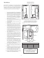
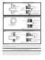
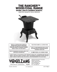
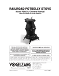
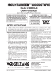
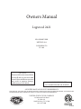
Owners Manual
Logwood 2421
EPA EXEMPT PER
METHOD 28A
CONFORMS TO
UL 1482
CAUTION!
Please read this entire manual before
you install and use your new room
heater. Failure to follow instructions
may result in property damage,
bodily injury or even death.
DO NOT USE THIS HEATER
IN A MOBILE HOME OR TRAILER
SAVE THIS MANUAL FOR FUTURE REFERENCE
THIS MANUAL WILL HELP YOU TO OBTAIN EFFICIENT, DEPENDABLE SERVICE FROM THE HEATER, AND ENABLE YOU
TO ORDER REPAIR PARTS CORRECTLY. KEEP IN A SAFE PLACE FOR FUTURE REFERENCE.
UNITED STATES STOVE COMPANY
227 Industrial Park Road
P.O. Box 151
South Pittsburg, TN 37380
(423) 837-2100
851094E
CONGRATULATIONS!
You've purchased a heater from North America's oldest manufacturer of wood burning products.
By heating with wood you're helping to CONSERVE ENERGY!
Wood is our only Renewable Energy Resource. Please do your part to preserve our wood supply.
Plant at least one tree each year. Future generations will thank you.
Tools and Materials Needed
MATERIALS
6" Elbow, Collar and Thimble; As Required
(24 gauge min.)
1/2" Sheet Metal Screws (No. 10A x 1/2")
6" Diameter, 24 gauge, black or blued steel
Underwriters Laboratories UL Listed
Residential Type HT (2100°F) Chimney or use a
Masonry Chimney in good repair.
Floor Protector Material (R value = 2.0) Minimum of
3'-0" x 4'-6" for US Standard
Furnace Cement (Manufacturer Recommends:
Rutland Black Code 78 or Equivalent)
6" Barometric Draft Regulator (DR-6)
TOOLS
Pencil
6 Foot Folding Rule or Tape Measure
Tin Snips
Drill, Hand or Electric
Drill Bit 1/8" Dia. (For Sheet Metal Screws)
Adjustable Wrench
Screw Driver (Blade-Type)
Gloves
Safety Glasses
HEATER DIMENSIONS
FIG. 1
38"
33"
31"
26-1/2"
16"
11-3/8"
5-1/4"
4-5/8"
28"
23"
9-3/8"
8"
FLOOR
PROTECTOR
FLOOR
PROTECTOR
2
25"
18-1/2"
Safety Rules
SAFETY NOTICE: If this heater is not properly installed a house fire may result. For your safety, follow the installation
directions. Contact local building or fire officials about restrictions and installation inspection requirements in your area.
Read these rules and the instructions carefully.
1.
2.
3.
4.
5.
6.
7.
8.
9.
Check with local codes. The installation comply with their rulings. Observe closely the clearances to combustibles (page 4).
Do not install this heater in a mobile home or trailer.
Always connect this heater to a chimney and vent to the outside.
Never vent to another room or inside a building.
Do not connect a wood burning heater to a Type B gas vent.
This is not safe and is prohibited by the National Fire Protection
Association Code. This heater requires approved masonry or
UL Listed Residential Type and Building Heating Appliance
Chimney. Use a 6" diameter chimney or larger, that is high
enough to give a good draft.
Be sure that your chimney is safely constructed and in good
repair. Have the chimney inspected by the Fire Department
or a qualified inspector. Your insurance company may be able
to recommend a qualified inspector.
Inspect chimney connector and chimney twice monthly during
the heating season for any deposit of creosote or soot which
must be removed (see Chimney Maintenance, page 9).
Provide air for combustion from outside the house into the
room where the heater is located. If the intake is not in the
same room, air must have free access in to the room.
To prevent injury, do not allow anyone to use this heater who
is unfamiliar with the correct operation of the heater.
For further information on using your heater safely, obtain
a copy of the National Fire Protection Association (NFPA)
publication "Using Coal and Wood Stoves Safely" NFPA No.
HS-10-1978. The address of the NFPA is Batterymarch Park,
MA 02269.
10. Disposal of Ashes - Ashes should be placed in a metal container
with a tight fitting lid. The closed container of ashes should
be placed on a noncombustible floor or on the ground, well
away from all combustible materials, pending final disposal. If
the ashes are disposed of by burial in soil or otherwise locally
dispersed, they should be retained in the closed container until
all cinders have thoroughly cooled.
11. CAUTION- The special paints used on your heater may give
off some smoke while they are curing during the first few fires.
Build small fires at first.
12. CARING FOR PAINTED PARTS- This heater has a painted
jacket, which is durable but it will not stand rough handling
or abuse. When installing your heater, use care in handling.
Clean with soap and warm water when heater is not hot. DO
NOT use any acids or scouring soap, as these wear and dull
the finish. PAINT DISCOLORATION WILL OCCUR IF
THE HEATER IS OVERFIRED. FOLLOW OPERATING
INSTRUCTIONS CAREFULLY.
13. All persons, especially children, should be alerted to hazards
from high surface temperatures and kept away while in operation. Small children should not be left unsupervised when in
the room with the heater.
14. Keep the area adjacent to the heater free from all combustible
materials, gasoline, and other flammable vapors.
CAUTION! Do not touch the heater until it has cooled.
NOTE:
FOR YOUR SAFETY, WE RECOMMEND INSTALLING SMOKE DETECTORS IN YOUR HOME IF NOT ALREADY
INSTALLED.
3
MINIMUM CLEARANCE
TO COMBUSTIBLE WALLS
Installation
Place the heater on solid masonry or solid concrete. When the
heater is used on a combustible floor, use an Underwriters Listed
floor protector. The floor protector must comply with UL Standards
and have an R-value of 2.0. The base should cover under the unit,
extend at least 16" beyond the door of the heater and should extend
2" beyond the flue pipe if it is elbowed towards a wall (Fig. 5).
18"
458mm
(60"
1.
2.
3.
4.
5.
6.
7.
8.
9.
10.
11.
12.
13.
Uncrate and/or unpack the heater, removing all packing
material, being careful not to dispose of the Parts Bag.
Open the front feed door and remove the parts from
inside the stove. You should find the following: Hearth
Plate (1); Solid Damper (1); Lids (2); Pivoting Top (1);
Lid Support (1); Parts Package (1) containing nuts,
bolts, door handle, door latch and securing hardware;
Legs (4); Cast Iron Collar (1); Cast Iron Damper (1);
Baffle Assembly (1); Lid Lifter (1).
Place cardboard or other soft material adjacent to the
stove and carefully turn the stove onto its top side
(bottom facing up).
Attach hearth plate to the front of the stove in its
proper location.
Attach both rear and front legs to the stove. Tighten
the nuts and bolts securely. The stove may now be
CAREFULLY turned over to stand on its four legs.
Attach the baffle assembly and flue collar to the stove
by inserting the baffle studs thru the two holes located
on the top of the rear of the stove; place the flue collar over the studs and mount using the proper nuts
and washers. Place lid support and lid in position on
pivoting top. Place the slide damper in position on the
top of the hearth plate and under the feed door, and
secure with screw in slot.
After consulting the installation instructions for
minimum clearances to combustibles, locate your floor
protector accordingly and carefully place the stove in
your selected location. Install stove pipe, elbows and
thimble as necessary, utilizing either a recently cleaned
and inspected masonry chimney (properly lined) or a
UL Listed chimney. Insure that the damper provided
is installed in the flue collar.
Again, check the following illustrations and be sure
you have the clearances shown from the heater and
the connector pipe to combustible surfaces. If you
have a solid brick or stone wall behind your heater,
you may place your heater as close as you wish to the
wall. However, if the wall is only faced with brick or
stone, consider it a combustible wall.
If your chimney drafts excessively, purchase and use
a Barometric Draft Regulator (DR6 available from
factory).
The chimney connection should be as short as possible,
and the heater must have its own flue. Do not connect
this unit to a chimney flue serving other appliances.
Use three sheet metal screws in each stove pipe and or
elbow joint to firmly hold the pipe together.
Do not install this heater in a mobile home or trailer.
Check your local building and insurance codes. The
installation must comply with their rulings.
MIN.)
28"
712mm
37-1/2"
953mm
26"
660mm
34"
865mm
FIG. 2
28"
712mm
FIG. 3
20"
508mm
FLOOR
PROTECTOR
FLOOR
PROTECTOR
HEATER/FLOOR PROTECTOR LOCATION
(Dimensions are required for non-protected surfaces.
See chart for dimensions for protected surfaces.)
BACK WALL
BACK WALL
DASHED LINES
SHOW STRAIGHT
OUT CHIMNEY
CONNECTOR
NON- COMBUSTIBLE
CONSTRUCTION IN
ACCORDANCE WITH
NFPA 211
34"
865mm
26"
660mm
6"
153mm
60"
FLOOR
PROTECTOR
16"
407mm
6"
153mm
28"
6"
153mm
FIG. Protected Surfaces (NFPA 211)
Parallel
Corner
Side
Rear
12-inches
12-inches
12-inches
305-mm 305-mm 305-mm
CAUTION!
KEEP FURNISHINGS AND OTHER
COMBUSTIBLE MATERIALS
AWAY FROM THE HEATER.
4
28-3/4"
730mm
Operation of the Heater
1.
2.
3.
4.
5.
6.
7.
8.
BE SURE TO PUT A LAYER OF SAND OR FIREBRICK APPROXIMATELY 1 1/2" THICK IN THE BOTTOM OF THE
STOVE BEFORE STARTING FIRE.
Burn wood or wood products only. The wood should be air
dried for at least six months prior to use for maximum efficiency.
After the fire has been started and is burning satisfactorily, adjust
the rate of burning by opening or closing the draft damper wheel
on the feed door.
Never build extremely large fires in this type of heater as damage
to the heater or smoking may result.
Provide air into the room for combustion.
Do Not touch the heater after firing until it has cooled.
Do Not use a grate or elevate fire, build fire directly on hearth.
The fuel feed door must remain closed during operation.
FLUE CONNECTION-NON-COMBUSTIBLE WALL
NONCOMBUSTIBLE WALL
THIMBLE
COLLAR
PIPE
ELBOW
BAROMETRIC
DRAFT REGULATOR
PIPE
FIG. 5
Chimney Connection
MASONRY CHIMNEY
The masonry chimney must comply with UL codes. Before using an existing masonry chimney, clean the chimney and inspect the flue liner to be
sure it is safe to use. Make repairs before attaching the heater. See Page 3,
Item 5. Look at Fig. 6. The connector pipe and fittings you will need to
connect directly to a masonry chimney are shown. If the connector pipe
must go through a combustible wall before entering the masonry chimney,
consult a qualified masonry chimney dealer. The installation must conform
to local fire codes. DO NOT CONNECT THIS UNIT TO A CHIMNEY
FLUE SERVING ANOTHER APPLIANCE.
The chimney used for a heater must not be used to ventilate the cellar or
basement. If there is a cleanout opening at the base of the chimney, close
it tightly.
FLOOR PROTECTOR
CHIMNEY CAP MANDATORY
2 FT. MIN
UL LISTED CHIMNEY
Carefully follow chimney manufacturer's instructions. Use only listed type HT
per UL 103, 6-in diameter black or blued chimney connector, minimum 24
gauge steel. If your chimney starts at the ceiling (Fig. 7), you will need enough
6" pipe to reach the ceiling.
The top of the chimney must be at least 3 feet above the roof and be at least 2
feet higher than any point of the roof within 10 feet. (Fig 6)
3 FT. MIN.
10 FT.
PIPE REDUCER
11 FT. MINIMUM
RULES FOR CONNECTOR PIPE INSTALLATION
1.
2.
3.
4.
5.
6.
7.
Crimped end of the pipe must be installed toward the heater. The pipe
should slide into the flue collar. The pipe should be firmly attached to
the flue collar with 3 screws and sealed with furnace cement.
Slope any horizontal pipe upward toward the chimney at least 1/4 "
inch for each foot of horizontal run.
You must have at least 18" inches clearance between any horizontal
piping and the ceiling. (Fig. 4)
The pipe cannot extend into the chimney flue.(Fig. 8)
Seal each connector pipe joint with furnace cement. Also seal the
pipe at the chimney.
Use 3 sheet metal screws at each joint to make the piping rigid.
It is recommended that no more than two (2) 90 degree bends be used
in the stove pipe installation as more than two (2) may decrease the
amount of draw and possibly cause smoke spillage.
NOTE: The chimney connector shall not pass through an attic,
roof space, floor, ceiling, or similar concealed space. Where passage through a wall or partition of combustible construction is
desired, the installation must conform with NFPA 211.
5
BAROMETRIC
DRAFT REGULATOR
PIPE
NONCOMBUSTIBLE
CONSTRUCTION IN
ACCORDANCE WITH
NFPA 211
FIG. 6
FLOOR PROTECTOR
RIGHT
WRONG
FIG. 7
WRONG
CONNECTION OF CHIMNEY CONNECTOR TO A MASONRY CHIMNEY THROUGH A COMBUSTIBLE WALL
Figure 8 shows how to connect the chimney connector of a heater to a masonry chimney through a combustible wall.
There are five allowable ways that a chimney connector can be connected to a masonry chimney by passing through a combustible
wall. NFPA Standard 211 allows the following wall pass-through systems.
CHIMNEY FLUE
FIGURE 8 CONNECTION OF CHIMNEY CONNECTOR TO A
MASONRY CHIMNEY THROUGH A COMBUSTIBLE
WALL
CEILING
SEE PARTS A, B,
C, D, AND E OF
THIS FIGURE FOR
OPTIONS.
CHIMNEY CONNECTOR
MASONRY CHIMNEY
CONSTRUCTED TO
NFPA 211
TO
HEATER
COMBUSTIBLE WALL
FLOOR
PROTECTOR
AIRTIGHT
CLEANOUT
DOOR
(FIGURE 8 CONTINUED ON NEXT PAGE)
6
MINIMUM CHIMNEY CLEARANCE TO
BRICK AND COMBUSTIBLES IS 2 IN.
MINIMUM 12 IN.
TO COMBUSTIBLES
CHIMNEY FLUE
PART A, FIGURE 8
(FIGURE 8 CONTINUED ON NEXT PAGE)
MASONRY CHIMNEY
CONSTRUCTED TO
NFPA 211
MINIMUM CLEARANCES 12 IN.
OF BRICK ALL AROUND
CHIMNEY CONNECTOR
TO HEATER
FIRE CLAY LINER
(5/8" MIN. WALL THICKNESS)
MIN. 3-1/2" THICK BRICK
MASONRY WALL
1. Use a minimum 3-1/2" thick brick masonry wall framed into the combustible wall. A fireclay liner (ASTM C315 or
equivalent) having a 5/8" minimum wall thickness must be used and it must be at least 12" away from any material that could catch
fire. The inside diameter of the fireclay liner shall be sized for the proper snug fit of a 6" diameter chimney connector pipe. The
fireclay liner shall run from the outer surface of the brick wall to, but not beyond, the inner surface of the chimney flue and shall be
firmly cemented in place. See Part A of Figure 8.
2. Use a solid insulated listed factory-built chimney length having an inside diameter of 6" and having 1" or more of solid insulation.
There must be at least a 9" air space between the outer wall of the chimney length and any combustible materials. The inner end of
the chimney length shall be flush with the inside of the masonry chimney flue shall be sealed to the flue and to the brick masonry
penetration with nonwater-soluble refractory cement. Sheet steel supports which are at least 24 gauge(0.024") in thickness shall be
securely fastened to wall surfaces on all sides. Fasteners between supports and the chimney length shall not penetrate the chimney
liner. See Part B of Figure 8.
3. Use a 10" diameter ventilated thimble made of at least 24 gauge(0.024") steel having two 1" air channels. The ventilated thimble
must be separated from combustible materials by a minimum of 6" glass fiber insulation. The opening in the combustible wall shall
be covered and the thimble supported with sheet steel supports which are at least 24 gauge (0.024") in thickness. The sheet steel supports shall be securely fastened to wall surfaces on all sides and shall be sized to fit and hold the chimney section. Fasteners used to
secure chimney sections shall not penetrate chimney flue liner. See Part C of Figure 8.
4. Use an 8" inside diameter solid insulated listed factory-built chimney length which has 1" or more of solid insulation. The
minimum length of this chimney section shall be 12" and will serve as a pass-through for the 6" diameter chimney connector. There
must be at least a 12" air space between the outer wall of the chimney section and any combustible materials. The chimney section
shall be concentric with and spaced 1" away from the chimney connector by means of sheet steel support plates on both ends of the
chimney section. The opening in the combustible wall shall be covered and the chimney section supported on both sides with sheet
steel supports which are at least 24 gauge (0.024") in thickness. The sheet steel supports shall be securely fastened to wall surfaces
on all sides and shall be sized to fit and hold the chimney section. Fasteners used to secure chimney sections shall not penetrate
chimney flue liner. See Part C of Figure 8.
5. A listed factory-built wall pass-through system may be purchased and installed according to the instructions packaged with it
to provide a safe method of passing the chimney connector through a combustible wall for connection to a masonry chimney.
Additional requirements pertaining to Figure 8 and the above wall pass-through systems:
1. Insulation material used as part of wall pass-through system shall be of noncombustible material and shall have a
thermal conductivity of 1.0 Btu • in./ft.² • °F (4.88 kg • cal/hr • m² • °C) or less
2. All clearances and thicknesses are minimums: larger clearances and thickness are acceptable.
3. A chimney thimble, as shown for 3" and 4" above (Parts C and D respectively of Figure 8) shall be for types "3" and 4" connections to facilitate removal of the chimney connector for cleaning. The chimney thimble shall be of ASTM C315 fireclay with 5/8"
minimum wall thickness , or material or equivalent durability. The inside diameter of the thimble shall be sized for the proper snug
fit of a 6" diameter chimney connector pipe. The thimble shall be installed without damage to the chimney flue. The thimble shall
extend through the chimney wall to, but not beyond, the inner surface of the chimney flue and shall be permanently cemented in
place with high temperature cement.
4. A chimney connector to a masonry chimney, except for 2" above (Part B of Figure 8), shall extend through the wall pass-through
system to the inner face of the chimney flue, but not beyond. It does not have to be fastened in place so long as it cannot accidently
be pulled out of the chimney or shoved into the chimney flue. If fasteners are used to secure the chimney connector to a masonry
chimney, the fasteners shall not penetrate the chimney flue liner.
5. Any material used to close up any opening for the connector shall be noncombustible.
7
PART B
FIGURE 8 (FIGURE 8 CONTINUED)
NONSOLUBLE
REFACTORY
CEMENT
AIR SPACE
FACTORY-BUILT
CHIMNEY LENGTH
CHIMNEY FLUE
MINIMUM CHIMNEY CLEARANCES FROM MASONRY TO
SHEET STEEL SUPPORTS AND COMBUSTIBLES 2 IN.
CHIMNEY LENGTH
FLUSH WITH INSIDE
OF FLUE
AIR SPACE
9 IN. MINIMUM
MINIMUM CLEARANCE
9 IN. ALL AROUND
CHIMNEY CONNECTOR
TO HEATER
USE CHIMNEY MFRS. PARTS TO
ATTACH CONNECTOR SECURELY
SOLID INSULATED, LISTED
FACTORY-BUILT CHIMNEY LENGTH
MASONRY CHIMNEY CONSTRUCTED
TO NFPA 211
PART C
FIGURE 8
SHEET STEEL SUPPORTS
(24 GAUGE MIN. THICKNESS)
MINIMUM CHIMNEY CLEARANCES FROM MASONRY TO
SHEET STEEL SUPPORTS AND COMBUSTIBLES 2 IN.
24 GAUGE
VENTILATED THIMBLE WITH
TWO 1 INCH AIR CHANNELS
CHIMNEY FLUE
CHIMNEY THIMBLE
TWO VENTILATED AIR
CHANNELS EACH 1 INCH.
CONSTRUCTED OF
SHEET STEEL.
MASONRY CHIMNEY CONSTRUCTED
TO NFPA 211
PART D
FIGURE 8
CHIMNEY CONNECTOR
TO HEATER
MINIMUM 6 IN. GLASS
FIBER INSULATION ALL AROUND
SHEET STEEL SUPPORTS
(24 GAUGE MIN. THICKNESS)
MINIMUM CHIMNEY CLEARANCES FROM MASONRY TO
SHEET STEEL SUPPORTS AND COMBUSTIBLES 2 IN.
SHEET STEEL SUPPORTS
MINIMUM CLEARANCE
2 IN. ALL AROUND
CHIMNEY SECTION
1 IN. AIR SPACE TO
CHIMNEY LENGTH
CHIMNEY THIMBLE
CHIMNEY FLUE
CHIMNEY
CONNECTOR
AIR SPACE
2 IN.
MASONRY CHIMNEY CONSTRUCTED
TO NFPA 211
CHIMNEY CONNECTOR
TO HEATER
SOLID INSULATED, LISTED
FACTORY-BUILT CHIMNEY
LENGTH (12 IN. LONG MIN.)
SHEET STEEL SUPPORTS
(24 GAUGE MIN. THICKNESS)
PART E - (Figure 8)
In addition to the methods shown by A, B, C, and D of Figure 8, a listed factory-built wall pass-through system may be purchased and
installed according to the instructions packaged with it to provide a safe method of passing chimney connector through a combustible
wall for a connection to a masonry chimney.
CONNECTION OF CHIMNEY CONNECTOR TO A MASONRY CHIMNEY WHEN CHIMNEY CONNECTOR
DOES NOT PASS THROUGH A COMBUSTIBLE WALL
If the chimney connector does not have to pass through a combustible wall to get to a masonry chimney, simply connect the chimney
connector directly to the masonry chimney's chimney thimble as described and shown by parts C and D of Figure 8. Remember,
the chimney connector should extend into the chimney thimble to the innerface of the chimney flue but not beyond; if the chimney
connector is extended through the chimney thimble into the chimney flue, resistance to the flow of smoke and gases up the chimney
will occur; that flow resistance will have an adverse affect on the operation and performance of the heater and venting system.
8
WARNING!
NEVER STORE FLAMMABLE LIQUIDS,
ESPECIALLY GASOLINE. IN THE
VICINITY OF THE HEATER.
CAUTION!
NEVER USE GASOLINE, GASOLINE-TYPE
LANTERN FUEL, KEROSENE, CHARCOAL
LIGHTER FLUID, OR SIMILAR
LIQUIDS TO START OR "FRESHEN UP" A
FIRE IN THE HEATER. KEEP ALL SUCH LIQUIDS
WELL AWAY FROM THE HEATER WHILE IT IS IN
USE
CAUTION!
OVERFIRING THE APPLIANCE MAY
CAUSE A HOUSE FIRE. IF A UNIT OR
CHIMNEY CONNECTOR GLOWS, YOU
ARE OVERFIRING.
CAUTION!
USE WOOD OR WOOD-LIKE MATERIALS
ONLY. DO NOT USE COAL OR
CHARCOAL. COAL OR CHARCOAL WILL
DESTROY THE FIREBOX. DO NOT USE
DRIED LUMBER OR TREATED WOOD.
WARNING!
NEVER OPERATE THIS HEATER WITH THE FUEL
DOOR OPEN.
NOTE:
DO NOT ELEVATE FIRE OR USE WITH A GRATE BUILD FIRE DIRECTLY ON THE HEARTH.
WARNING!
USE ONLY THE LEGS PROVIDED WITH THIS
HEATER. REFER TO STEP 5 IN THE "INSTALLATION"
SECTION OF THIS MANUAL.
WARNING!
DO NOT OBSTRUCT THE SPACE BENEATH THE
HEATER
Service Hints
Do not expect a heater to draw. It is the chimney that creates the
draft. Smoke spillage into the house or excessive buildup of water
or creosote in the chimney are warnings that the chimney is not
functioning properly. Correct problem before using heater. Possible causes are:
1.
The connector pipe may be pushed into the chimney too far,
stopping the draft. (Fig. 7)
2.
Do not connect two heaters into the same chimney flue.
3.
The chimney used for a heater must not be used to ventilate
the cellar or basement. If there is a cleanout opening at the
base of the chimney, It must be closed tightly.
4.
If the chimney is operating too cool, water will condense in
the chimney and run back into the stove. Creosote formation
will be rapid and may block the chimney. Operate the heater
at a high enough fire to keep the chimney warm preventing
this condensation.
5.
If the fire burns well but sometimes smokes or burns slowly, it
may be caused by the chimney top being lower than another
part of the house or a nearby tree. The wind blowing over a
house or tree, falls on top of the chimney like water over a dam,
beating down the smoke. The top of the chimney should be at
least 3 feet above the roof and be at least to 2 feet higher than
any point of the roof within 10 feet (Fig. 6).
Chimney Maintenance
Creosote - Formation and Need for Removal
If creosote has accumulated, it should be removed. Failure to remove creosote may cause a house fire. Creosote may be removed
by using a chimney brush or other commonly available materials.
When wood is burned slowly, it produces tar and other organic
vapors, which combine with expelled moisture to form creosote.
The creosote vapors condense in the relatively cool chimney flue of
a slow-burning fire. As a result, creosote residue accumulates on the
flue lining. When ignited this creosote makes an extremely hot fire.
Chimney fires burn very hot. If the chimney connector should glow
red, immediately call the fire department, then reduce the fire by
closing the inlet air control and pour a large quantity of coarse salt,
baking soda or cool ashes on top of the fire in the firebox. CAUTION: A chimney fire may cause ignition of wall studs or rafters
which you thought were a safe distance from the chimney. If you
have a chimney fire, have your chimney inspected by a qualified
person before using again.
The chimney connector and chimney should be inspected at least
twice monthly during the heating season to determine if a creosote
buildup has occurred.
9
Model 2421
Repair Parts
KEY
PART NO.
DESCRIPTION
QNTY.
1
2
3
4
5
6
7
8
9
10
11
12
13
14
15
16
17
18
19
20
21
22
*
40319
40319
40320
40321
40322
40323
40324
40325
40326
40327
40329
40330
40331
40332
D6
83427
40334
89971
89972
89973
89974
89975
851094
REAR LEG
FRONT LEG
MAIN BOTTOM
MAIN SIDE
MAIN BACK
HEARTH PLATE
SLIDING DRAFT PLATE
DOOR FRAME
DOOR
MAIN TOP
LID
LID SUPPORT
LID LIFTER
FLUE COLLAR
SOLID FLUE DAMPER
DOOR PINS
DRAFT CONTROL KNOB
HANDLE
LATCH
NUTS
HANDLE EXTENSION
HANDLE BRACKET
OWNERS MANUAL
2
2
1
2
1
1
1
1
1
1
2
1
1
1
1
2
1
1
1
2
1
1
1
* NOT SHOWN
10
IN ORDER TO MAINTAIN
WARRANTY, COMPONENTS
MUST BE REPLACED USING
ORIGINAL MANUFACTURERS
PARTS PURCHASED THROUGH
YOUR DEALER OR DIRECTLY
FROM THE APPLIANCE
MANUFACTURER. USE OF
THIRD PARTY COMPONENTS
WILL VOID THE WARRANTY.
FLOOR PROTECTOR
The stove must be placed on solid concrete, solid masonry, or when installed on a combustible floor, on a Type 2 floor protector listed to standard
UL 1618 with a minimum R value of 3.0 and a minimum thickness of 1” or equivalent. The floor protector is required to provide heat, live ember, and
ash protection and must be of a non-combustible, continuous solid surface to protect against infiltration of live embers and ash. For UL Listed floor
protectors, refer to manufacturers instructions for installation directions. Manufacturers of listed floor protectors include Imperial Metal Products and
Hy-C among others. To calculate R-Values for alternative methods, see below for calculation methods.
Alternate materials may be rated with C-factor (Thermal Conductance) or k-factor (Thermal Conductivity) ratings which must be converted to R-value
to determine if the alternate material meets the tested requirements. The following instructions provide the proper information and formulas for
conversion to R-value.
To determine if alternate materials are acceptable follow this sequence.
1. Convert material specifications to R-value:
a. R-value given — no conversion necessary
b. k-factor is given with a required thickness (T) in inches: R = 1/k x T
c. C-factor is given: R = 1/C
2. Determine the R-value of proposed alternate floor protector:
a. Use formulas in step 1 above to calculate R-value of proposed material(s).
b. For multiple layers, add R-values of each layer to determine overall R-value.
3. If the overall R-value of the floor protector system is equal to or greater than the floor protector specifications given, the alternate is acceptable.
Definitions:
Thermal conductance (C) =
Thermal conductivity (k) =
Thermal resistance (R) =
BTU
(hr)(ft²)(°F)
(Btu)(inch)
(hr)(ft²)(°F)
(hr)(ft²)(°F)
BTU
=
=
=
W
(m²)(°K)
W
=
(m²)(°K)
BTU
(hr)(ft²)(°F)
(m²)(°K)
W
Example:
The specs of floor protector material should be 3/4-inch thick material with a k-factor of 0.84. The proposed alternative material is 4” brick with a
C-factor of 1.25 over 1/8-inch mineral board with a k-factor of 0.29.
Step 1: Convert specs to R-value.
R = 1/k x T = 1/0.84 x 0.75 = 0.893 System must have a R-value of 0.893 = Rspecs
Step 2: Calculate R-value of individual components
4” Brick with C-factor = 1.25. R = 1/C = 1/1.25 = 0.80 = Rbrick
1/8-inch (0.125”) mineral board with k-factor = 0.29. R = 1/0.29 x 0.125 = 0.431 = Rmin.brd.
Step 3: Add R-values of components to get total R-value of system
Rbrick + Rmin.brd = 0.80 + 0.431 = 1.231 = Rsystem
Step 4: Compare Rsystem to Rspecs
Rsystem = 1.231 is larger than Rspecs of 0.893. System R-value exceeds the required specifications and therefore is an acceptable alternative.
11
HOW TO ORDER REPAIR PARTS
THIS MANUAL WILL HELP YOU OBTAIN EFFICIENT, DEPENDABLE SERVICE FROM THE
HEATER, AND ENABLE YOU TO ORDER REPAIR PARTS CORRECTLY.
KEEP IN A SAFE PLACE FOR FUTURE REFERENCE.
WHEN WRITING, ALWAYS GIVE THE FULL MODEL NUMBER WHICH IS ON THE NAMEPLATE ATTACHED TO THE BACK OF THE HEATER.
WHEN ORDERING REPAIR PARTS, ALWAYS GIVE THE
FOLLOWING INFORMATION AS SHOWN IN THIS LIST:
1. The PART NUMBER
2. The PART DESCRIPTION
3. The MODEL NUMBER: 2421
4. The SERIAL NUMBER:
UNITED STATES STOVE COMPANY
227 Industrial Park Road
P.O. Box 151
South Pittsburg, TN 37380
(423) 837-2100
www.USSTOVE.com