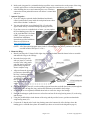
1
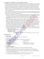
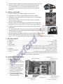
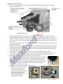
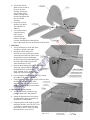
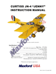
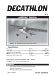
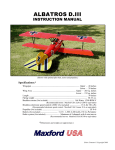
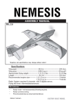
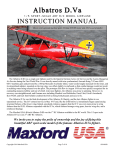
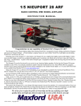
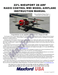
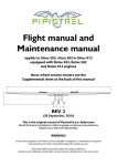
L-4 “Grasshopper”
1/6 SCALE ARF RADIO CONTROL SPORT-SCALE AIRPLANE
INSTRUCTION MANUAL
Shown with optional electric power system
and 11 x 6 wooden propeller.
The Piper J-3 Cub is a small, simple, light aircraft that was built between 1937 and 1947 by Piper
Aircraft. With tandem (fore and aft) seating, it was intended for flight training, but became one of the
most popular and best-known light aircraft of all time.
Piper developed a military variant variously designated as the O-59 (1941), L-4 (after April 1942), and
NE (U.S. Navy). The variety of models, as well as similar, tandem-cockpit accommodation aircraft from
Aeronca and Taylorcraft, were collectively nicknamed “Grasshoppers” and used extensively in World
War II for reconnaissance, transporting supplies, and medical evacuation. In Europe, the final dogfight of
WWII occurred between an L-4 and a German Fieseler Fi-156 Storch. The pilot and co-pilot of the L-4,
Lts. Duane Francis and Bill Martin, opened fire on the Storch with their pistols, forcing the German air
crew to land and surrender.
After the war, most L-4s were destroyed or sold as surplus, but a few saw service in the Korean War.
The Grasshoppers sold as surplus in the U.S. were redesignated as J-3s, but often retained their wartime
glazing and paint.
This 1/6 scale RC model airplane is made of balsa, light-ply and fiberglass, and is based on L-4
“Grasshopper” S/N: 45-4496 which is currently owned and operated by the Air National Guard in the
state of New Mexico.
We invite you to enjoy the pride of ownership and the joy of flying
this beautiful model of the famous L-4 Grasshopper.
TABLE OF CONTENTS
I.
II.
III.
IV.
Safety Precautions & Assembly Tips ..............
Warranty, Liability Waiver & Return Policy ..
Parts List ...........................................................
Special Features ...............................................
2
3
3
4
V.
VI.
VII.
VIII.
Page 1 of 10
Specifications .......................................
Assembly Instructions ..........................
Setup & Adjustments ...........................
Transport & Preflight Checks ..............
4
4
9
9
S110729 / Copyright 2011
I. SAFETY PRECAUTIONS & ASSEMBLY TIPS:
(IMPORTANT – READ THIS SECTION BEFORE YOU BEGIN ASSEMBLY)
1. This product should not be considered a toy, but rather a sophisticated, working model that functions much
like a full-scale airplane. Because of its performance capabilities, this product, if not assembled and operated
correctly, could cause injury to you or spectators and damage to property. Maxford USA provides you with a
high-quality, thoroughly tested model airplane kit with assembly instructions. However, the quality and
capabilities of your finished model airplane depend on how you assemble it, and your safety depends on how
you use and fly it. Any testing or flying of this model airplane is done entirely at your own risk.
2. Assemble this model airplane according to these instructions. Do not alter or modify the model beyond the
assembly and power system options covered in these instructions, as doing so may result in an unsafe or
unworkable model. If the instructions differ from the photos, the written instructions should be considered as
correct. If you have any question or concern about these instructions, before you proceed with assembly of
this product, contact your dealer or speak to a Maxford USA customer service representative at 562-529-3988
(Monday through Friday, except national holidays, 9 AM to 5 PM Pacific time).
3. While this kit has been flight-tested to meet or exceed our rigid performance and reliability standards in
normal use, if you elect to perform any extremely high-stress flying, such as racing or advanced aerobatics, or
if you install a larger power system than specified, you (the buyer or user of this product) are solely
responsible for taking any and all necessary steps to reinforce the high-stress points and/or substitute
hardware that is more suitable for such increased stresses.
4. Throughout the lifetime of this model, use only the Maxford USA-supplied or a same-sized motor and a new
or well-maintained radio-control system and batteries recommended by Maxford USA or your radio system.
5. It is your responsibility to install the receiver and connect the R/C components in such a way that this model
airplane passes all applicable safety/range tests and that the power system and controls operate correctly and
smoothly.
6. Recheck the operation of this model airplane before every flight to ensure that all equipment is still operating
correctly and that the model has remained structurally sound. Also before every flight, check all electrical,
control and structural connections; do not fly without replacing any that you find damaged or worn.
7. Before you begin assembly of this model airplane, read all instructions and test-fit each part to ensure you
fully understand the instructions and that no parts are missing, damaged or unsatisfactory.
(Note: Temperature and/or humidity differences between the factory, our warehouse and your home or
workshop may indicate the need for slight adjustments to the wing saddle, struts and/or the vertical or
horizontal stabilizer’s mounting surfaces to ensure proper alignment of these surfaces; however, we
recommend you contact us before you attempt any such adjustments.)
8. To help ensure the security of your servo connections, we recommend use of optional
Maxford USA servo extension safety clips.
9. If you are not an experienced R/C pilot or have not flown this type of model before,
we strongly urge you to get assistance from an experienced R/C pilot.
10. You may apply 30-minute epoxy to permanently attach critical parts (such as where the horizontal and
vertical stabilizer attach at the end of the fuselage) and apply a thread lock compound to secure the engine’s
or motor’s mounting hardware from vibration.
11. If you have concern about the security of any factory fabrication procedure(s), you may apply 30-minute
epoxy around the perimeter of such part(s) as an extra safety precaution.
12. This model includes some plastic, fiberglass and/or carbon-fiber reinforced parts. If you drill, grind or sand
such a part, always wear safety goggles, a particle mask and rubber gloves to guard yourself from eye, skin
and respiratory-tract irritation and never blow into the part (the dust may blow back into your face).
13. Check the Mylar covering material’s joints and surfaces; if necessary, carefully use a dedicated coveringmaterial iron (do NOT set the iron’s temperature too high) to secure the edges and to tighten any loosened
areas. Recheck and retighten from time to time.
14. Read all instructions included with your battery and charger. Failure to follow all instructions could result in
permanent damage to the battery, its surroundings, and bodily harm! If you crash this model airplane, check
whether the battery is damaged. Do NOT attempt to use or recharge a damaged battery.
Page 2 of 10
S110729 / Copyright 2011
II. WARRANTY, LIABILITY WAIVER & RETURN POLICY:
Maxford USA guarantees this kit to be free from defects in material and workmanship at the time of purchase.
All our products have been inspected in our factory and are checked again when shipped from our warehouse.
However, Maxford USA cannot directly control the materials you may use nor your final assembly process.
Therefore, Maxford USA can NOT in any way guarantee the performance of your finished model airplane.
Furthermore, in purchasing this product, you (the buyer or user of this product) exempt, waive, and relieve
Maxford USA from all current or future liability for any personal injury, property damage, or wrongful death,
and if you (the buyer or user of this product) are involved in any claim or suit, you will not sue Maxford USA
or any of its representatives.
If you do not fully accept the above liability and waiver, you may request a return-merchandise authorization
number (RMA#) as explained below in item 2. If you think there is a missing, damaged or unsatisfactory part,
please read our after-sales service and return policy:
1. Inspect your order upon delivery for any missing, damaged or unsatisfactory part(s). If you believe there is
a problem, you must call us at 562-529-3988 (Monday through Friday except holidays, between the hours
of 9 AM and 5 PM Pacific time) before you begin assembly and within 10 days from receipt of your
purchase. During this telephone conversation, and with your support, we will determine how to resolve
your concern.
2. To request a return-merchandise authorization number (RMA#), call 562-529-3988 (Monday through
Friday except holidays, between the hours of 9 AM to 5 PM Pacific time). If we elect to issue you an
RMA#, you must clearly mark this RMA# on the outside of the package. (No return or exchange will be
authorized after 10 days from the date of your receipt of the product; any package delivered to us without a
Maxford USA RMA# is subject to being returned to the sender, as received, with return postage payable
upon delivery.) Returned merchandise must be in its original condition as received from Maxford USA,
with no assembly or modification, in the product’s original packing materials, complete with all manuals
and accessories. Return shipping and insurance charges must be prepaid by you, the buyer.
3. Returned merchandise that is accepted by Maxford USA for credit is subject to a 10% to 20% restocking
fee (the final amount will be determined by Maxford USA upon receipt and examination of the returned
merchandise). Return Address:
Maxford USA RC Model Mfg, Inc.
15247 Texaco Avenue
Paramount, CA 90723
IMPORTANT: Print the RMA# issued by Maxford USA near the above address.
III. PARTS LIST:
1. Included items
•
•
•
•
•
•
•
•
All wood built-up construction, precovered with iron-on Mylar film.
Windshield (with mounting screws).
Wing panels with V-shaped left & right wing struts and prehinged ailerons.
Horizontal stabilizer & elevator.
• Stearable tail gear.
Vertical Stabilizer & Rudder
• Hardware bag.
• Complete set of scale markings.
Main landing gear assembly.
• This illustrated Instruction Manual.
Scale-looking landing gear with wheels.
Engine mount.
2. Items you must supply
• 5-minute epoxy and thin cyanoacrylate (CA) adhesives, thread-locking compound.
• Masking tape and common hand tools (such as screwdrivers, long-nosed and cutting pliers, etc.).
• A four (or more) channel radio system, 5 ea. HS311 or equivelant standard servos (or 4 standard servos
plus an electronic speed control if you use an electric power system), 2 ea. 12-inch servo extensions and
1 ea. 6-inch Y cable for aileron servos.
• 40- to 46-sized 2-cycle engine (or equivalent 4-cycle engine or electric power system.
• 11 x 6 wood prop. (or as recommended by the maker of your engine or motor).
Page 3 of 10
S110729 / Copyright 2011
• Optional upgrades: Dashboard, throttle control, dummy engine and floats.
• Options required for EP conversion: U35425 motor, 60A electronic
speed control (ESC), 2 ea. 3 cell 2100 mAh LiPo batteries, and
connectors (to run the batteries in parallel and connect the batteries
to the ESC).
IV. SPECIAL FEATURES:
• Fully operational top- and bottom-hinged cabin side door.
• Prepainted cowl, realistic looking windshield with side windows.
• Landing gear with mains wheels and steerable tail wheel, and markings
for L-4 S/N: 45-4496.
• Quick-disconnect struts and easily removable two-piece wing panels
for easy storage and transport.
• Fuselage, wings and empennage are jig-assembled, laser-cut balsa and
light plywood; the preapplied finish is quality Mylar covering material.
• Designed with semi-symmetrical wing for better sport-scale aerobatic
performance.
• 95% preassembled ARF, designed for glow engine (with supplied engine mount
and fuel tank for .40-sized glow engine) and an available motor mounting box
for electric power operation.
• Optional upgrades: Prepainted detailed true-to-scale dashboard, throttle control,
dummy engine and floats. These items may also be used in our yellow
Piper J-3 Cub. (The dashboard and the throttle control are assembled and painted here in the USA.)
V. SPECIFICATIONS:*
•
•
•
•
•
Wingspan ....................................................................................................................................... 71 inches
Wing area ....................................................................................................................... 697.5 square inches
Length ......................................................................................................................................... 48.4 inches
ARF weight ...................................................................................................................... 3 pounds 6 ounces
Power system ............................ 40- to 46-sized 2-cycle engine (engine mount and fuel tank are included)
(Optional: Equivalent 4-cycle engine or electric power system)
• Propeller .............................................. 11 x 6 (or as recommended by the maker of your engine or motor)
• Radio (not included) ................................................................................................ Minimum of 4 channels
• Servos ......................................................................... 5 standard-sized servos (Hitec HS311 or equivalent)
(4 standard-sized servos when using an optional electric power system)
* (Dimensions and weights are approximate.)
VI. ASSEMBLY INSTRUCTIONS:
1. Fuselage-Mounted Servos –
a. Remove the built-up and
covered fuselage from its plastic
bag.
b. Position the fuselage right-side
up to get access to the opening
in the top of the fuselage.
c. Using hardware supplied with
your servos, install the three
servos in the servo-tray.
d. Connect the pushrods to the
elevator and rudder servo horns
as shown at the right.
NOSE
Page 4 of 10
S110729 / Copyright 2011
2. Engine (or Motor) and Cowl –
a. Test-fit your engine, the engine mount, fuel lines, throttle pushrod and all related engine-mounting
hardware as shown below.
b. Using the spacing required by your engine’s mounting lugs, drill holes in the engine mounts and use
engine mounting bolts, washers and nuts (#6-7-8 above) to securely attach your engine to the engine
mounts. Test-fit the engine to the firewall using the vertical and horizontal guide-lines drawn on the fire
wall to set the prop. shaft with the recommended amount of right thrust and down thrust. Drill 4 holes in
the firewall.
c. Use engine mounting bolts (#4 above) and blind nuts (install the blind nuts behind fire wall) to attach the
engine to the fire wall.
d. Drill a hole and direct the throttle pushrod (#10 above) from the throttle servo through the firewall. (Be
careful to position the throttle pushrod’s hole so it will not interfere with the engine mount or fuel tank.)
e. Position the fuel tank (#1 above) on its shelf inside the fuselage behind the firewall with the clunk and
vent fuel lines passing through the firewall.
f. In preparation to mount the engine cowl (#9 above), remove the muffler from your engine.
g. As dictated by the design and dimensions of your engine, make opening in the engine cowl to access
your engine’s needle valves, allow cooling air into the cowl, and to let the muffler exit the cowl.
h. Attach the engine’s muffler to the engine with its provided hardware.
i. If you are using the optional dummy engine, attach the engine parts to both sides
of the cowl at this time. Position the cowl so the propeller backplate protrudes
approx. 1/4 inch beyond the face of the cowl; use masking tape to temporarily
hold the cowl in position; drill guide holes through the cowl and into the edge of
the firewall; use small screws to attach the cowl; remove the masking tape.
If you install an electric power system …
a) Position your batteries on the shelf behind the firewall.
b) Position the optional motor mounting box and your motor on the
firewall as described above to
obtain the recommended amount of
right thrust and down thrust.
Protect the mounting bolts from
vibration with thread lock
compound or CA adhesive.
Page 5 of 10
S110729 / Copyright 2011
c) Attach your ESC and confirm that the motor runs in the correct direction by connecting the ESC’s
throttle lead to your radio receiver’s throttle channel; switch ON your transmitter and set transmitter’s
throttle and throttle trim controls to minimum; with no propeller on the motor, switch ON your
transmitter and connect the ESC to the battery; after you hear a series of initialization sounds, slowly
raise the transmitter’s throttle to no more than 25% of maximum.
d) Carefully run the motor slowly and only for the few seconds necessary to observe its direction of
rotation. If the motor rotated in the clockwise (correct) direction as viewed from the rear of the
airplane, return the throttle to minimum, disconnect the ESC from the battery, switch OFF the
transmitter, and set your battery and transmitter aside. However, if the motor powered up in the
counterclockwise (wrong) direction, return the throttle control to minimum, disconnect the ESC from
the battery, swap either two of the three ESC-to-motor wires, and repeat the above procedure to
ensure the motor rotates in the correct direction.
3. Mains Landing Gear Assembly –
(NOTE: If you will use floats, replace this section with the detailed instructions included with the floats.)
a. Turn the fuselage up-side down. If necessary, spread the main landing gear assembly’s crossmember
wires to align with the precut slots located under the Mylar covering material as shown below.
(IMPORTANT: Do NOT cut away the covering over the slots; instead, leave the Mylar covering
material to be pressed into these slots to help keep the wood inside each slot from getting soaked with
any residual exhaust oil.)
b. Make a clean ‘slice’ in
the Mylar from sideto-side over the midstruts
line of each slot.
c. Position the landing
gear’s front and rear
crossmembers over
their slots to help
locate and poke ‘open’
the Mylar covering the
predrilled mounting
screw holes.
d. Press the landing
gear’s front and rear
crossmember wires
into their slots. Using
the supplied mounting
screws (#5), install the
four hold-down plates
(#4, two across each
cross-member).
e. Locate the wheel collars (#3) as shown and secure each mains wheel (#2) to its axle by tightening the set
screw in each wheel collar.
4. Tail Surfaces –
a. Test-fit the vertical stabilizer, rudder, horizontal stabilizer and two halves of the elevator.
(IMPORTANT: The elevator will REMAIN in two separate halves; one half will be installed on each
side of the vertical stabilizer – otherwise you will not be able to insert the horizontal stabilizer through
its slot at the end of the fuselage.)
b. Slide the horizontal stabilizer through the slot at the end of the fuselage. Center and align the horizontal
stab. at a right angle to the centerline of the fuselage, and secure it in place with thin CA adhesive.
c. Using the supplied CA hinges and thin CA, attach the two halves of elevator to the horizontal stabilizer.
Page 6 of 10
S110729 / Copyright 2011
d. Test-fit the vertical
stabilizer into its slot at
the top rear of the
fuselage. (Ensure the
lower portion of the
rudder will align with
but not bind against the
lower end of the
fuselage.)
e. Secure the vertical
stbilizer (#1) into its
slot with thin CA
adhesive.
f. Test-fit the rudder’s
control horn and
both elevator
control horns as
shown at the right.
Securely attach all three control horns:
One on the rudder and one on each half of the elevator.
Elevator’s
control
horns
5. Tail Wheel –
a. Test-fit all the pieces of the tail wheel
assembly as shown at the right.
b. Install two wheel collars (#3).
(NOTE: One wheel collar prevents the
vertical portion of the tail wheel’s strut
from being forced upward through
the hole in the tail gear mounting plate;
the other wheel collar keeps the tail
wheel attached to its axle.)
c. Position the mounting plate (#4) and insert the
sharp end of the tail wheel’s strut into
the predrilled hole in the rudder;
using 5-minute epoxy, secure the
sharp end of the strut inside the rudder.
d. Use the supplied CA hinges and thin CA to attach
the rudder to the vertical stabililzer.
e. Using the photo at the right as a guide, make sure that
the tail gear can rotate freely in the
mounting plate (#4) and use screws to
attach the mounting plate to the bottom
of the fuselage.
6. Ailerons and Aileron Servos –
a. Test-fit the ailerons with their wing
panels, control horns and pushrods.
b. Attach an aileron horn to each aileron.
(Predrilled holes show the position of
each aileron’s control horn.)
c. Using the picture at the right as a guide,
mount the aileron servos. (NOTE: Use a
12-inch servo extension in each wing
panel and a 6-inch Y cable to connect
the extensions to your receiver.
Page 7 of 10
/
d. Inside each wing panel is a preinstalled string to pull the servo extension wires to the center of the wing;
carefully pull each servo extension through each wing panel for connection to your Y-cable.
e. After installing the servos and connecting the servo extensions,
connect the aileron pushrods between each aileron’s control horn
and servo.
7. Optional Upgrades –
a. If you are using the optional detailed dashboard and throttle
control, position these items inside the cockpit and secure them
at this time with thin CA adhesive.
b. You may also add one or two Maxford USA 1/5-scale pilot
figures inside the top- and bottom-hinged opening side door.
c. If you have access to a suitable body of water, you may replace
the fixed landing gear with a set
of 40-sized Maxford USA floats.
(HINT: You may preview the
detailed float installation
instructions provided with these
floats on our Website at
www.maxfordusa.com.)
(NOTE: All of the optional upgrade items for the L-4 Grasshopper may also be purchased for use with
our ARF model of the Piper J-3 Cub.)
8. Mount the Wing –
a. Identify and stage the V-shaped left & right wing struts and related materials shown below to assemble
and attach the wing to the fuselage.
b. Insert the front joiner (#6)
and rear joiner (#7) into the
root ribs of the wing panels
and slide the left and right
panels firmly together to
form a complete wing.
c. Align and insert the plywood
projections at the middle of
the wing’s leading edge with
the opening behind the
‘windshield’ in the fuselage,
then gently lower the wing
onto the fuselage’s wing
saddle.
6. Front joiner
d. Place the hold-down plate (#3) over the trailing edge and insert the two hold-down bolts (#4) through the
holes in the plate, through the wing, and into the blind nuts preinstalled in the fuselage.
e. Snug (but do not over-tighten) both hold-down bolts to secure the wing to the fuselage.
f.
Place the Grasshopper upside down on a soft surface and test-fit the wing bracing struts (#5) to the wing
and fuselage.
g. Using the predrilled holes in the bottom of the wing and the provided screws, position and attach the
wing bracing struts (#5).
h. Connect the V-shaped end of each wing bracing strut to the bottom side of the fuselage where the
landing gear’s rear hold-down plates are attached (as shown as item #4 in the diagram on page 6).
Page 8 of 10
S110729 / Copyright 2011
VII. SETUP & ADJUSTMENTS:
1. Ensure all parts are secure and ready for flight.
2. Check and if necessary adjust the center of gravity: Your L-4 must balance when lifted at a point approx.
3 inches (76 mm) behind the leading edge of the wing (i.e., it must hang level; neither nose up nor nose
down).
3. Check/adjust servo centering, direction and end-point adjustments: When you pull the right stick toward
you, the elevator should deflect upwards; push the right stick to the right and the right aileron should deflect
upwards and the left aileron should deflect downwards; push the left stick left and the rudder should deflect
to the left as viewed from the rear of the fuselage. If you are using a Computer Radio: For initial flights
set all linkages for near-max. possible deflections; then soften the aileron’s and elevator’s control throws by
selecting 60% or more exponential (use 30% exponential for the rudder). Initial settings if you are using a
Non-Computer Radio:
Recommended Deflection
Elevator ...................................... 15 degrees (5/8 inches) up and down from center
Rudder ........................................ 20 degrees (7/8 inches) left and right from center
Ailerons ...................................... 12 degrees (1/2 inches) up and down from center
4. Check the Mylar covering material’s joints and surfaces. If necessary, carefully use a dedicated coveringmaterial iron to secure the edges and to tighten any loosened areas. Recheck and retighten from time to
time. (Be carefull to NOT use too much heat when you secure edges or tighten the Mylar!)
5.
6.
Ensure all preapplied stick-on insignias and markings are secure in their positions.
Balance your propeller, then use the hardware supplied with your engine or motor to securely attach
the propeller to the engine or motor.
Congratulations! Assembly is finished!
VIII. TRANSPORT & PREFLIGHT CHECKS:
1. Prepare your Grasshopper for transport and storage by disconnecting the struts at the fuselage and removing
the hold-down bolts that secure the wing to the fuselage; safely set aside the wing hold-down bolts and wing
hold down plate for future use. As you lift the wing away from the fuselage, carefully disconnect both
aileron servo extensions from the Y-cable. Separate the wing panels from their joiners and safely transport
or store your Grasshopper to await its next flight.
2. To prepare your Grasshopper for flight, reattach the wings by reversing the above
procedure. As you position the wing above the fuselage, guide the aileron servo
extensions into the fuselage and reconnect them to the aileron’s Y-cable. (To help
ensure the security of these servo connections, we recommend use of optional
Maxford USA servo extension safety clips.)
3. With the wing and aileron extensions neatly and safely reconnected and properly
positioned, align and insert the plywood projections at the middle of the wing’s
leading edge into the opening behind the ‘windshield’ in the fuselage, gently lower the wing onto the
fuselage’s wing saddle, reinstall the hold-down plate over the trailing edge, then insert and ‘snug’ (but do
not over-tighten) the two hold-down bolts to secure the wing to the fuselage.
4. Double-check the security of your engine (or the motor and its motor-mounting box) and make certain that
all control surfaces, pushrods, screws and other connections are secure throughout the air frame.
5. Double-check the control directions and amount of control throw of the ailerons, elevator and rudder.
6. As with all radio-controlled model airplanes, your Grasshopper must pass the radio range ground check
recommended by your radio’s manufacturer or you may not fly safely.
7. Be sure your tank is filled with the fuel recommended by the manufacturer of your engine (or the batteries
are fully charged and able to provide the current demanded by your electric power system).
8. Whether you use a glow engine or an electric motor, for your safety we urge you to get into the habit of
always moving your transmitter’s throttle to MINIMUM before turning ON your transmitter, and carefully
operate your choice of radio and power system according to the manufacturer’s instructions.
Page 9 of 10
S110729 / Copyright 2011
9. If you are using a glow engine: Start the engine and set the needle valve according to your engine
manufacturer's instructions. Advance the throttle to ‘full speed’ then lift and hold the Grasshopper at a
45-60 degree nose-up attitude for 10-15 seconds; during this time the engine should run smoothly with no
appreciable loss of RPM. However, if your engine’s RPM ‘sags’ noticeably or if the engine dies from
being either too rich or too lean, readjust the engine’s high speed needle valve according to the engine
manufacturer’s instructions.
10. Whenever possible, point the nose of your Grasshopper into the wind for take off. As you advance the
throttle, keep the nose pointed straight ahead as your Grasshopper picks up speed. Then, after the tail has
lifted off and when you feel confident your Grasshopper has achieved adequate flying speed, give only a
slight amount of UP elevator to gently climb to a safe manuevering altitude.
Congratulations on your new L-4 Grasshopper.
May you enjoy many Happy Landings!
However, please remember …
• The quality and capabilities of your finished model airplane depend on how you assemble it.
• This product is NOT a toy.
• Your safety depends on how you use and fly it.
• Any testing, flying and use of this model airplane is done entirely at your own risk.
• Please enjoy your hobby and fly safely!
Manufactured by:
Maxford USA RC Model Mfg, Inc.
15247 Texaco Avenue
Paramount, CA 90723
Telephone (voice) ............ (562) 529-3988
Fax .................................... (562) 562-6988
Toll free (orders only) ..... (866) 706-8288
Website ................ www.maxfordusa.com
Order replacement parts, servos, gas engines, batteries, brushless motors,
electronic speed controls, and a wide variety of other high-quality RC hobby
items online at www.maxfordusa.com.
Page 10 of 10
S110729 / Copyright 2011